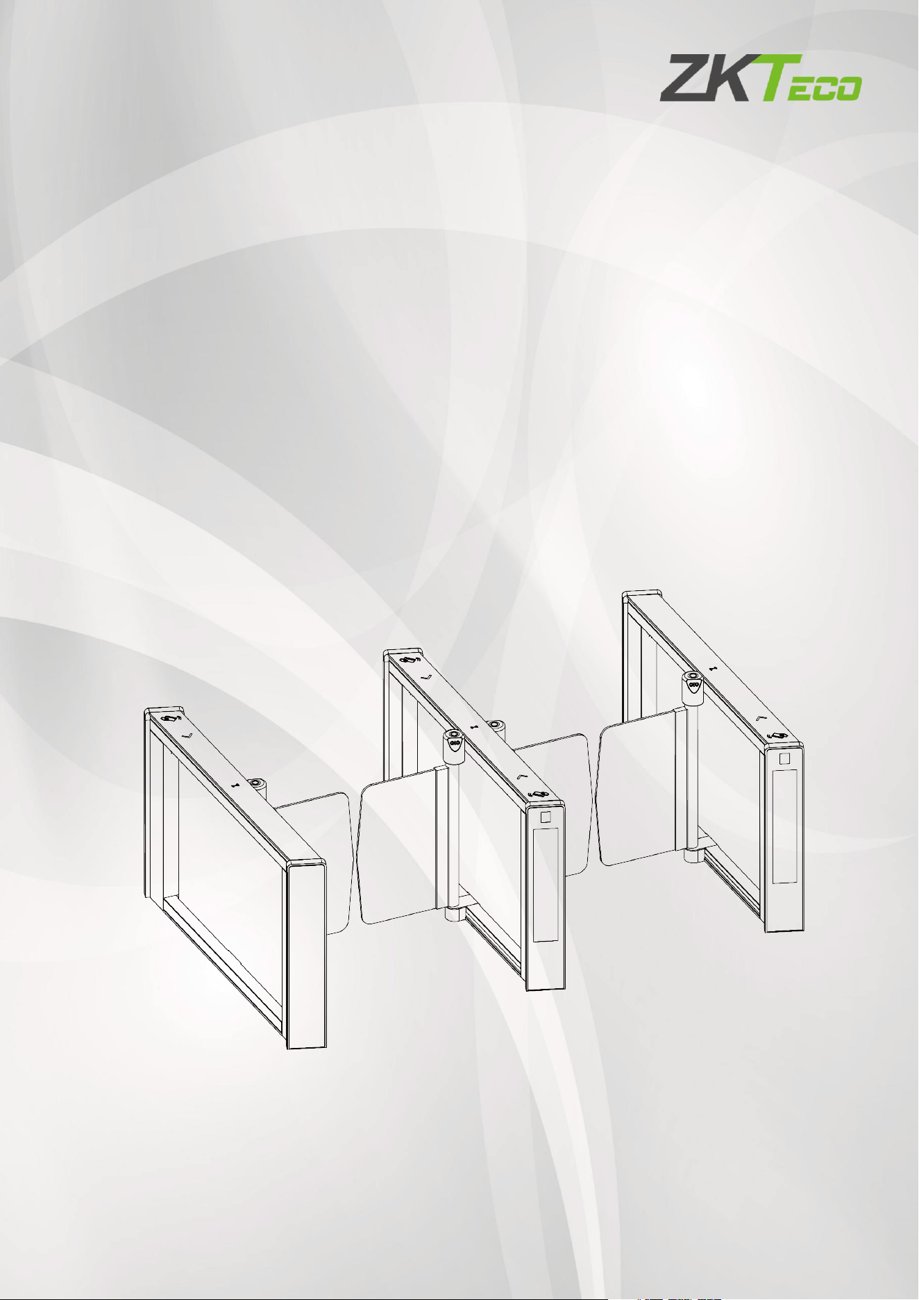
mTS1000 Series Tripod Turnstile User Manual
Page | 1 Copyright©2026 ZKTECO CO., LTD.All Rights Reserved.
User Manual
Saturn-S4000 Series
Applicable Model(s): Saturn-S4000, Saturn-S4200
Date: March 2026
Doc Version: 1.0
English

Saturn-S4000 Series User Manual
Page | 1 Copyright©2026 ZKTECO CO., LTD.All Rights Reserved.
Copyright © 2026 ZKTECO CO., LTD. All rights reserved.
Without the prior written consent of ZKTeco, no portion of this manual can be copied or forwarded in any
way or form. All parts of this manual belong to ZKTeco and its subsidiaries (hereinafter the "Company" or
"ZKTeco").
Trademark
is a registered trademark of ZKTeco. Other trademarks involved in this manual are owned by
their respective owners.
Disclaimer
This manual contains information on the operation and maintenance of the ZKTeco equipment. The
copyright in all the documents, drawings, etc. in relation to the ZKTeco supplied equipment vests in and is
the property of ZKTeco. The contents hereof should not be used or shared by the receiver with any third
party without express written permission of ZKTeco.
The contents of this manual must be read as a whole before starting the operation and maintenance of the
supplied equipment. If any of the content(s) of the manual seems unclear or incomplete, please contact
ZKTeco before starting the operation and maintenance of the said equipment.
It is an essential pre-requisite for the satisfactory operation and maintenance that the operating and
maintenance personnel are fully familiar with the design and that the said personnel have received
thorough training in operating and maintaining the machine/unit/equipment. It is further essential for the
safe operation of the machine/unit/equipment that personnel has read, understood and followed the
safety instructions contained in the manual.
In case of any conflict between terms and conditions of this manual and the contract specifications,
drawings, instruction sheets or any other contract-related documents, the contract conditions/documents
shall prevail. The contract specific conditions/documents shall apply in priority.
ZKTeco offers no warranty, guarantee or representation regarding the completeness of any information
contained in this manual or any of the amendments made thereto. ZKTeco does not extend the warranty
of any kind, including, without limitation, any warranty of design, merchantability or fitness for a particular
purpose.
ZKTeco does not assume responsibility for any errors or omissions in the information or documents which
are referenced by or linked to this manual. The entire risk as to the results and performance obtained from
using the information is assumed by the user.
ZKTeco in no event shall be liable to the user or any third party for any incidental, consequential, indirect,
special, or exemplary damages, including, without limitation, loss of business, loss of profits, business
interruption, loss of business information or any pecuniary loss, arising out of, in connection with, or

Saturn-S4000 Series User Manual
Page | 2 Copyright©2026 ZKTECO CO., LTD.All Rights Reserved.
relating to the use of the information contained in or referenced by this manual, even if ZKTeco has been
advised of the possibility of such damages.
This manual and the information contained therein may include technical, other inaccuracies or
typographical errors. ZKTeco periodically changes the information herein which will be incorporated into
new additions/amendments to the manual. ZKTeco reserves the right to add, delete, amend or modify the
information contained in the manual from time to time in the form of circulars, letters, notes, etc. for better
operation and safety of the machine/unit/equipment. The said additions or amendments are meant for
improvement /better operations of the machine/unit/equipment and such amendments shall not give any
right to claim any compensation or damages under any circumstances.
ZKTeco shall in no way be responsible (I) in case the machine/unit/equipment malfunctions due to any
non-compliance of the instructions contained in this manual (ii) in case of operation of the
machine/unit/equipment beyond the rate limits (iii) in case of operation of the machine and equipment in
conditions different from the prescribed conditions of the manual.
The product will be updated from time to time without prior notice. The latest operation procedures and
relevant documents are available on http://www.zkteco.com
If there is any issue related to the product, please contact us.
ZKTeco Headquarters
Address ZKTeco Industrial Park, No. 32, Industrial Road,
Tangxia Town, Dongguan, China.
Phone +86 769 - 82109991
Fax +86 755 - 89602394
For business-related queries, please write to us at: [email protected]m
.
To know more about our global branches, visit www.zkteco.com.

Saturn-S4000 Series User Manual
Page | 3 Copyright©2026 ZKTECO CO., LTD.All Rights Reserved.
About the Company
ZKTeco is one of the world’s largest manufacturer of RFID and Biometric (Fingerprint, Facial, Finger-vein)
readers. Product offerings include Access Control readers and panels, Near & Far-range Facial Recognition
Cameras, Elevator/floor access controllers, Turnstiles, License Plate Recognition (LPR) gate controllers and
Consumer products including battery-operated fingerprint and face-reader Door Locks. Our security
solutions are multi-lingual and localized in over 18 different languages. At the ZKTeco state-of-the-art
700,000 square foot ISO9001-certified manufacturing facility, we control manufacturing, product design,
component assembly, and logistics/shipping, all under one roof.
The founders of ZKTeco have been determined for independent research and development of biometric
verification procedures and the productization of biometric verification SDK, which was initially widely
applied in PC security and identity authentication fields. With the continuous enhancement of the
development and plenty of market applications, the team has gradually constructed an identity
authentication ecosystem and smart security ecosystem, which are based on biometric verification
techniques.With years of experience in the industrialization of biometric verifications, ZKTeco was officially
established in 2007 and now has been one of the globally leading enterprises in the biometric verification
industry owning various patents and being selected as the National High-tech Enterprise for 6 consecutive
years. Its products are protected by intellectual property rights.
About the Manual
This manual introduces the operations of Saturn-S4000 Series.
All figures displayed are for illustration purposes only. Figures in this manual may not be exactly consistent
with the actual products.
Features and parameters with ★ are not available in all devices.
Saturn-S4000 Series User Manual
Page | 4 Copyright©2026 ZKTECO CO., LTD.All Rights Reserved.
Safety Instruction
These instructions are intended to ensure that user can use the product correctly to avoid danger or
property loss.
The precaution measure is divided into Dangers and Cautions:
Dangers: Neglecting any of the warnings may cause serious injury or death.
Cautions: Neglecting any of the cautions may cause injury or equipment damage.
Symbols
Convention Description
Dangers: Follow these safeguards to prevent serious injury or death.
Cautions: Follow these precautions to prevent potential injury or material damage.
Dangers:
In the use of the product, you must be in strict compliance with the electrical safety regulations of the
nation and region.
The equipment must be connected to an earthed mains socket-outlet.
Shock hazard! Disconnect all power sources before maintenance.
Do not touch the bare metal contacts of the inlets after the circuit breaker is turned off. Electricity still
exists.
To prevent possible hearing damage, do not listen at high volume levels for long periods.
All the electronic operation should be strictly compliance with the electrical safety regulations, fire
prevention regulations and other related regulations in your local region.
Please use the power adapter, which is provided by normal company. The power consumption cannot
be less than the required value.
Do not connect several devices to one power adapter as adapter overload may cause over-heat or fire
hazard.
Please make sure that the power has been disconnected before you wire, install or dismantle the
device.
If the top caps should be open and the device should be powered on for maintenance, make sure:
1. Power off the fan to prevent the operator from getting injured accidentally.
2. Do not touch bare high-voltage components.
3. Make sure the switch's wiring sequence is correct after maintenance.
Please make sure that the power has been disconnected before you wire, install or dismantle the
device.

Saturn-S4000 Series User Manual
Page | 5 Copyright©2026 ZKTECO CO., LTD.All Rights Reserved.
If smoke, odors or noise rise from the device, turn off the power at once and unplug the power cable,
and then please contact the service center.
If the product does not work properly, please contact your dealer or the nearest service center. Never
attempt to disassemble the device yourself. (We shall not assume any responsibility for problems
caused by unauthorized repair or maintenance.)
The Terminal PE of the switch should be connected to a ground wire.
Cautions:
Instructions must be read before installation. Please follow these instructions carefully, incorrect
installation could affect gate operation.
When mounting and positioning this product please ensure the power cable is unplugged.
The motor cover will need to be removed to mount the motor to the mounting plate. Electrical-related
operation of the main unit can only be made by a licensed electrician.
To prevent injury, this equipment must be securely attached to the floor/base of the turnstile in
accordance with the installation instructions.
Keep straight down when moving or using the equipment.
Never place the equipment in an unstable location. The equipment may fall, causing serious personal
injury or death.
Cold-rolled SPCC steel may be corroded in some circumstances. You need to clean and care the device
by using the stainless steel cleaner. It is suggested to clean the device every month.
Do not drop the device or subject it to physical shock, and do not expose it to high electromagnetism
radiation. Avoid the equipment installation on vibrations surface or places subject to shock (ignorance
can cause equipment damage).
Do not place the device in extremely hot (refer to the specification of the device for the detailed
operating temperature), cold, dusty or damp locations, and do not expose it to high electromagnetic
radiation.
The device cover for indoor use shall be kept from rain and moisture.
Exposing the equipment to direct sun light, low ventilation or heat source such as heater or radiator is
forbidden (ignorance can cause fire danger).
Do not aim the device at the sun or extra bright places. A blooming or smear may occur otherwise
(which is not a malfunction however), and affecting the endurance of sensor at the same time.
Please use the provided glove when open up the device cover, avoid direct contact with the device
cover, because the acidic sweat of the fingers may erode the surface coating of the device cover.
Please use a soft and dry cloth when clean inside and outside surfaces of the device cover, do not use
alkaline detergents.
Please keep all wrappers after unpack them for future use. In case of any failure occurred, you need to
return the device to the factory with the original wrapper. Transportation without the original wrapper
may result in damage on the device and lead to additional costs.

Saturn-S4000 Series User Manual
Page | 6 Copyright©2026 ZKTECO CO., LTD.All Rights Reserved.
Improper use or replacement of the battery may result in hazard of explosion. Replace with the same
or equivalent type only. Dispose of used batteries according to the instructions provided by the
battery manufacturer.
Biometric authentication products are not 100% applicable to anti-spoofing environments. If you
require a higher security level, use multiple authentication modes.
Do not stay in the lane when the device is rebooting.
RISK OF EXPLOSION IF BATTERY IS REPLACED BY AN INCORRECT TYPE. DISPOSE OF USED BATTERIES
ACCORDING TO THE INSTRUCTIONS.
SUITABLE FOR MOUNTING ON CONCRETE OR OTHER NON-COMBUSTIBLE SURFACE ONLY.
The instructions shall require connection of the equipment protective earthing conductor to the
installation protective earthing conductor.

Saturn-S4000 Series User Manual
Page | 7 Copyright©2026 ZKTECO CO., LTD.All Rights Reserved.
Table of Contents
1 OVERVIEW ............................................................................................................................................ 9
Key Features ................................................................................................................................................. 10 1.1
Specification ................................................................................................................................................. 11
1.2
1.2.1
Appearance ............................................................................................................................................................................................... 11
1.2.2 System Components ........................................................................................................................................................................... 14
1.2.3 Technical Specifications .................................................................................................................................................................... 16
Mechanical System ...................................................................................................................................... 18 1.3
Electronic Control System .......................................................................................................................... 18
1.4
2
AUTHENTICATION METHODS ........................................................................................................... 19
Card Verification .......................................................................................................................................... 19 2.1
QR Code Verification ................................................................................................................................... 19
2.2
Fingerprint Verification
★ .......................................................................................................................... 20 2.3
Facial Verification
★ .................................................................................................................................... 21 2.4
3
INSTALLATION ................................................................................................................................... 22
Installation Tools .......................................................................................................................................... 22 3.1
Installation Requirements .......................................................................................................................... 22
3.2
Installation Environment ............................................................................................................................ 22
3.3
Installation Cabinet ..................................................................................................................................... 23
3.4
4
TERMINAL DESCRIPTION .................................................................................................................. 29
Primary and Secondary Board ................................................................................................................... 29 4.1
Access Control Module
★ ........................................................................................................................... 31 4.2
5
WIRING INSTRUCTIONS ..................................................................................................................... 33
Primary and Secondary Location .............................................................................................................. 33 5.1
Wiring Methods ............................................................................................................................................ 34
5.2
Power and Circuit Breaker Wiring ............................................................................................................. 35
5.3
System Wiring Diagram .............................................................................................................................. 36
5.4
6
OPERATION PROCESS ....................................................................................................................... 38
7 MACHINE OPERATION ....................................................................................................................... 40
Operation Buttons Description ................................................................................................................. 40 7.1
Menu Parameter Settings ........................................................................................................................... 40
7.2
8
LCD ADVERTISING SCREEN OPERATING INSTRUCTIONS................................................................ 46
Digital Signage App Installation Guide .................................................................................................... 46 8.1
CMS System User Guide .............................................................................................................................. 46
8.2
9
MAINTENANCE .................................................................................................................................. 51
Cleaning and Maintenance ........................................................................................................................ 51 9.1
Coating Inspection and Repair .................................................................................................................. 51
9.2
Mechanical Component Maintenance ..................................................................................................... 51
9.3

Saturn-S4000 Series User Manual
Page | 8 Copyright©2026 ZKTECO CO., LTD.All Rights Reserved.
Electrical Component Maintenance ......................................................................................................... 51 9.4
10
TROUBLESHOOTING ...................................................................................................................... 52
11 PACKING LIST ................................................................................................................................. 53
Saturn-S4000 Series User Manual
Page | 9 Copyright©2026 ZKTECO CO., LTD.All Rights Reserved.
1 Overview
ZKTeco’s Saturn-S4000 series redefines entrance control, fusing elegant industrial design with
intelligent security via advanced dToF sensors and multi-modal biometric authentication.
Saturn-S4000 series is driven by DC brushless motors, delivering smooth and quiet swing barrier
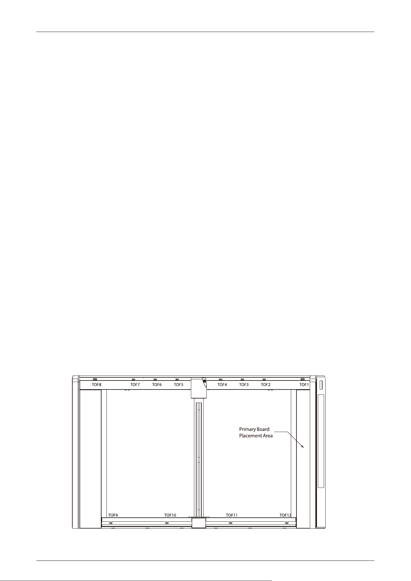
operation in just 0.3 to 0.6 seconds per movement. At its core, the 12 pieces dToF sensors enhances
detection accuracy, providing robust anti-tailgating and anti-pinch protection.
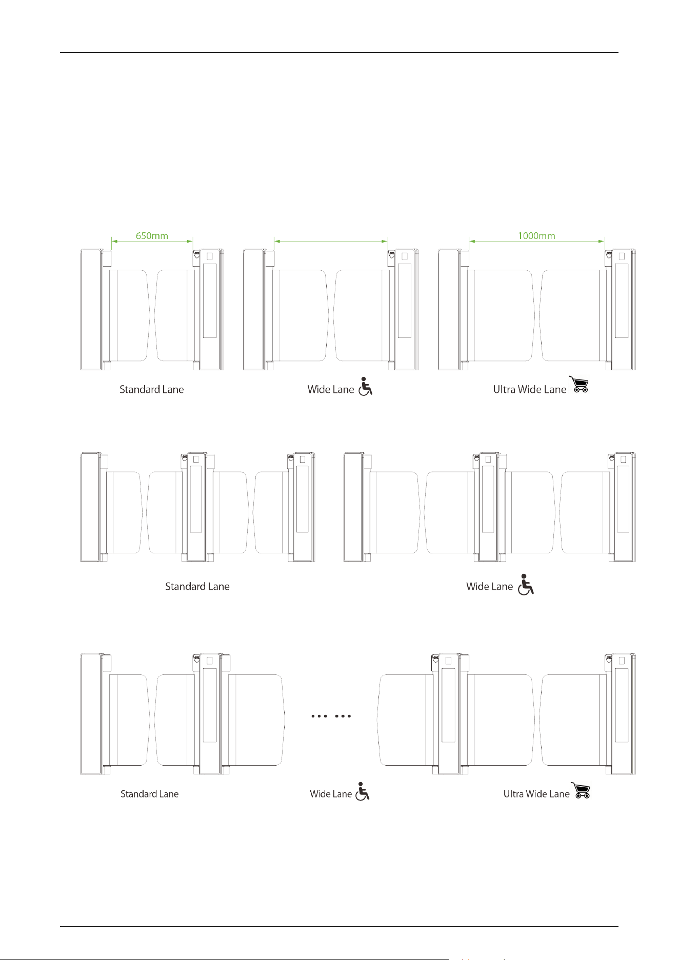
Available in single-lane (S4000) and dual-lane (S4200) configurations, the series offers a standard lane
width of 650mm and an optional 1,000mm wide lane width configuration to accommodate
wheelchair users and trolleys for enhanced accessibility.
What makes the Saturn-S4000 series stands out is its versatile multi-modal biometrics authentication.
User can choose under-mount RFID and fingerprint readers that preserve the tempered glass lid, or
add contactless QR code verification for visitor and temporary access. When facial and palm
authentication is required, simply mount the ZKTeco's Zophon facial recognition module on the
motor post—no hardware replacement needed.
Additionally, the Saturn-S4000 series maximizes business value with its integrated 23.9-inch vertical
dual LCD display. This full-color screen delivers promotional and branding content through vivid
video and photo slideshow playback, all managed remotely via Wi-Fi using the ZKDigimax Screen
Direct.

Saturn-S4000 Series User Manual
Page | 10 Copyright©2026 ZKTECO CO., LTD.All Rights Reserved.
Key Features 1.1
Aesthetic and Reliability
The top cover is covered with a single piece of black tempered glass. This design resists daily wear
while maintaining long-term operational stability.
User Experience
Tri-color LED indicators give clear status at a glance: blue for standby, green for entry, and red for
barrier closing or alarm, ensuring smooth and intuitive passage..
Compact Core Drive
A 60mm-diameter core drive module frees up internal space, enabling tighter cabinet dimensions
and slimmer gate profiles.
Front and Rear LCD Displays
The turnstile is equipped with dual LCD displays -- one on the front and one on the rear. A 23.9-
inch vertical color LCD display seamlessly embedded in the Saturn-S4000 gate column transforms
the lane into a dynamic digital media platform.
Saturn-S4000 Series User Manual
Page | 11 Copyright©2026 ZKTECO CO., LTD.All Rights Reserved.
Specification 1.2
1.2.1 Appearance
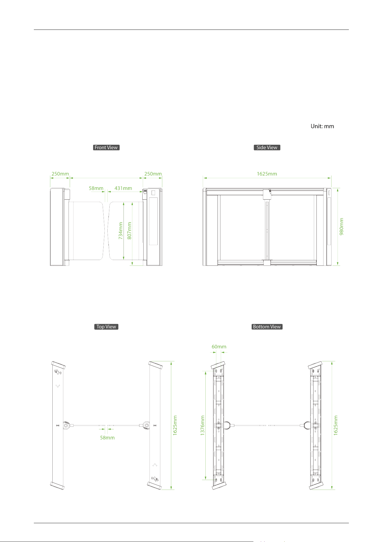
Saturn-S4000:
900mm
Saturn-S4000 Series User Manual
Page | 12 Copyright©2026 ZKTECO CO., LTD.All Rights Reserved.
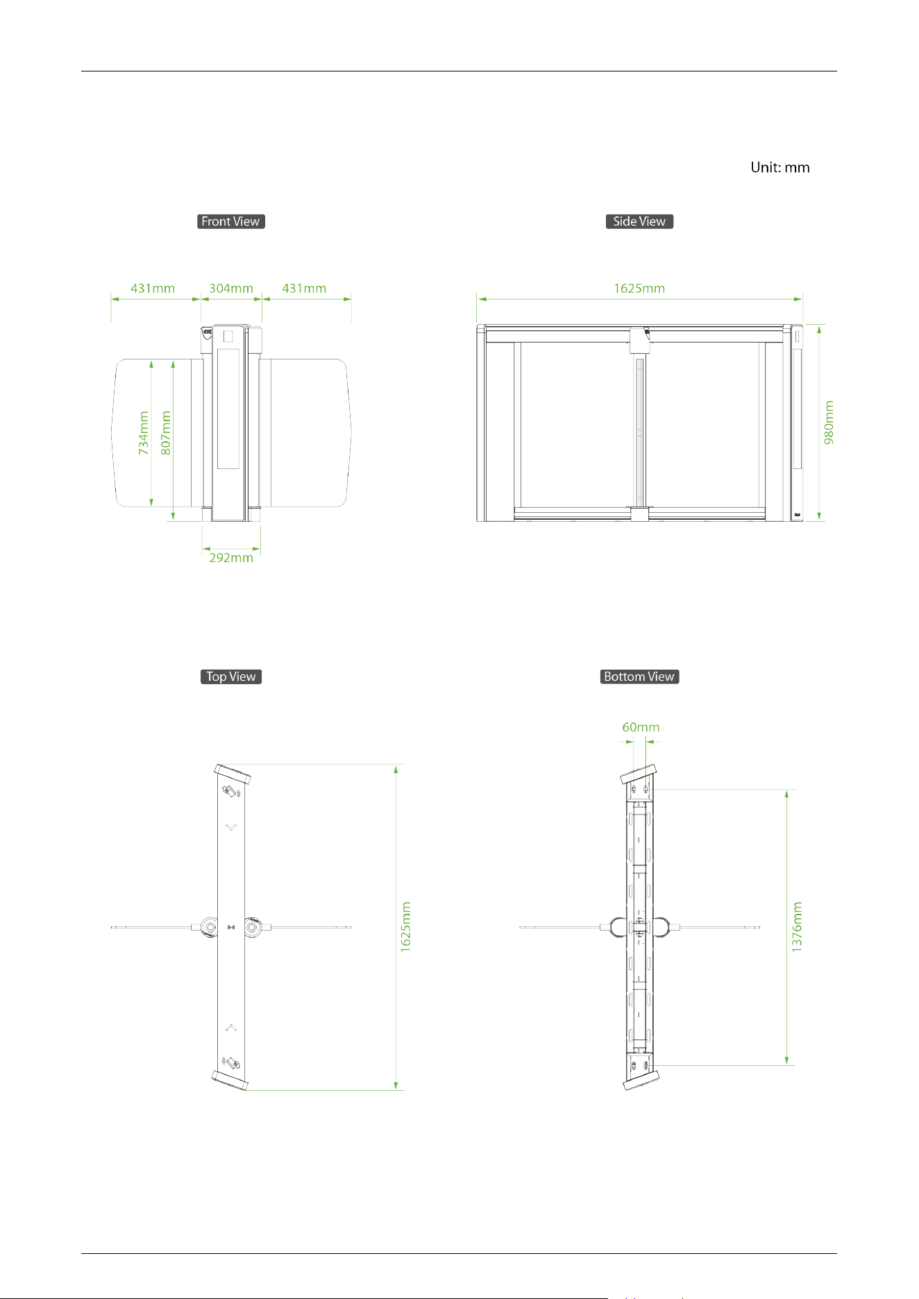
Saturn-S4200:
Saturn-S4000 Series User Manual
Page | 13 Copyright©2026 ZKTECO CO., LTD.All Rights Reserved.
2) Dual-
Swing Barriers Specifications
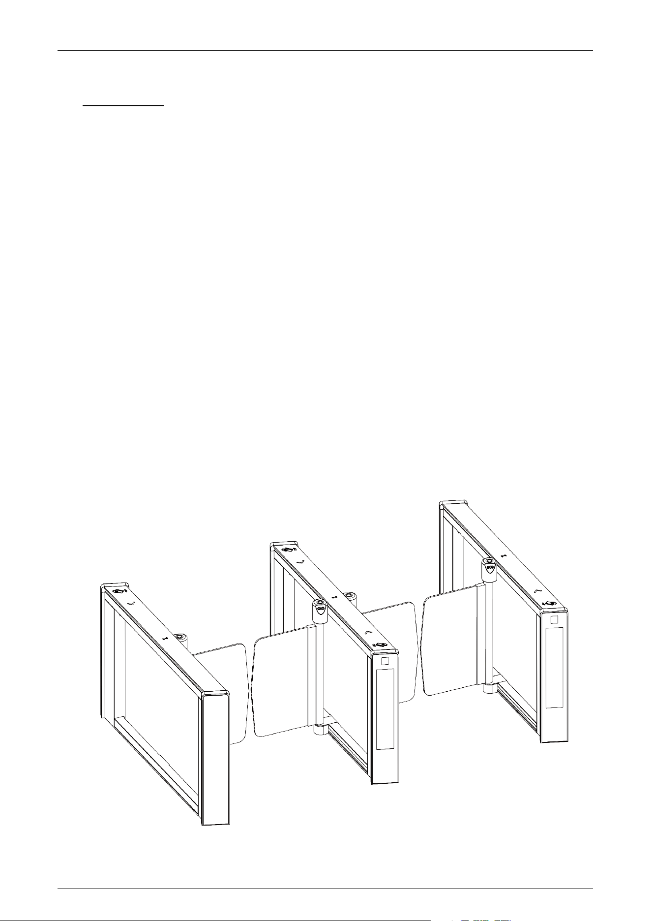
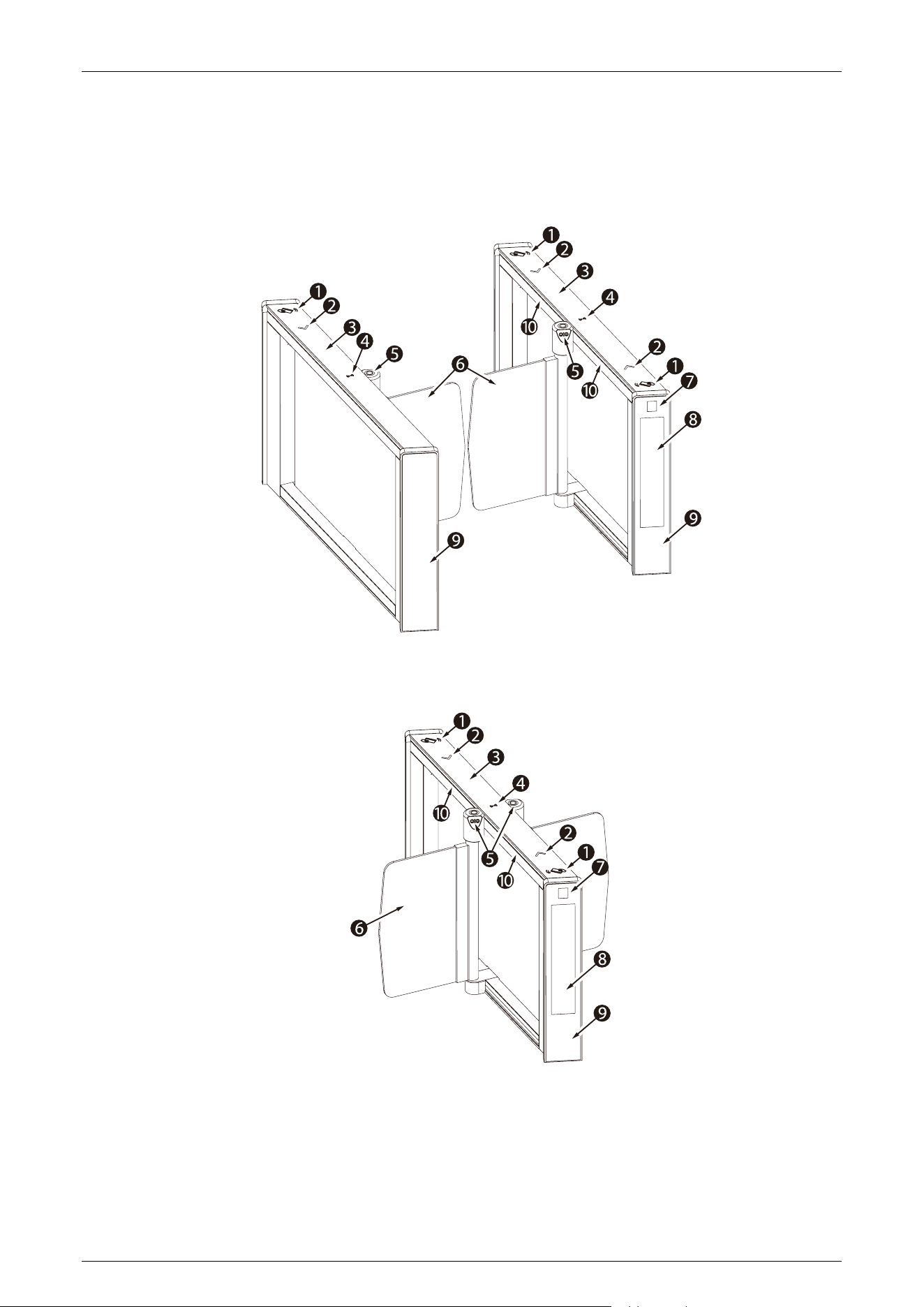
The Saturn-S4000 and Saturn-S4200 can be combined to form a single, dual or multi-lane system,
allowing the user to select the appropriate swing arm size according to actual needs. It should be
noted that Saturn-S4200 needs to be used in conjunction with Saturn-S4000.
1) Single-lane
lane
3) Multi-lane
900mm
Saturn-S4000 Series User Manual
Page | 14 Copyright©2026 ZKTECO CO., LTD.All Rights Reserved.
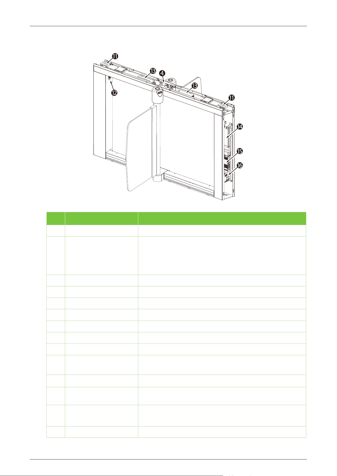
1.2.2 System Components
Saturn-S4000:
Saturn-S4200:
Saturn-S4000 Series User Manual
Page | 15 Copyright©2026 ZKTECO CO., LTD.All Rights Reserved.
Core Component
No. Components Descriptions
1
Card Reading Area RFID card module standard configuration.
2
Traffic Indicator
Top LED indicator:
Blue=Door closed/stand by
Green=Door opening
Red=Door closing/alarm
3
Top Lid Cold-rolled SPCC Steel (GB700)
4
NFC Optional
5
Multimodal Camera Facial Recognition Module (Zophon-S1000) (optional)
6
Door Leaf Door Leaf Material: Clear Acrylic(optional: Tempered Glass)
7
QR Code Module Optional
8
LCD Screen Optional
9
Side Pedestal
10
Sensor
It detects the position of the pedestrian and plays a role in ensuring
safety and protection.
11
Reader Module Not standard equipment
12
Speaker
To play alarms or alert voices. (On the back of the turnstile controller
board.)
13
Access control board
(Zophon-S1000)
Not standard equipment
14
Controller Board Primary/ Secondary Board, the system’s control center

Saturn-S4000 Series User Manual
Page | 16 Copyright©2026 ZKTECO CO., LTD.All Rights Reserved.
15
Power Supply 110V / 220V ±10% AC @50Hz/ 60Hz
16
Circuit Breaker
It provides reliable protection by automatically disconnecting the circuit
in the event of overload, short circuit, under voltage, or power loss.
1.2.3 Technical Specifications
Model Saturn-S4000 Saturn-S4200
Audio Indicator
Internal speaker
Visual Indicator
Top LED indicator:
Blue=Door closed /stand by
Green=Door opening
Red=Door closing/alarm
Display
23.9" LCD vertical non-touch dual display (1920x360)
Support file formats: jpg, jpeg, png, mp4; max. file size: 1GB (Max. no. of
uploads: 6 via ZKDigimax Screen Direct)
Support video and photo slideshow playback
Lane Type
Single lane Dual Swing (additional lane)
Lane Width
650mm (Standard)
1000mm (Optional)
Barrier Movement Type
Swing
Motor
DC brushless motor
Movement Speed
0.3 to 0.6s per movement (Adjustable open / close timing)
Lid Material
Tempered glass
Lid Options
Authentication Methods
Streamlined under mount: QR Code / RFID/ Fingerprint
Motor mount: palm, facial authentication
Chassis Material
Cold-rolled SPCC Steel (GB700)
Chassis Colour
Black & Matte White
Door Leaf Material (H*W)
Acrylic (734*300mm) ; (optional: 1734*438 mm)
Sensors
12 pcs of dToF sensors (standard) ; 20 pcs of dToF sensors (optional)
Motherboard Function
Supports four passage modes:
Verified Passage (requires identity verification before entry),
Free Passage (no verification required for direct entry),
Forbidden Passage (channel locked),
Constantly Open Passage (channel remains open continuously).
Motherboard
Communication
Fire alarm port (relay)*1, RS485 port*1

Saturn-S4000 Series User Manual
Page | 17 Copyright©2026 ZKTECO CO., LTD.All Rights Reserved.
Controller
N/A (Compatibility with C3-200 Plus / InBio260 Pro Plus series controller
available upon request)
Credential Options
Under mount RFID reader: ProID Series, KR Series
Under mount fingerprint reader: FR1200 / FR1500S
Under mount QR code reader: QR 500
Motor mount palm and facial recognition module: Zophon-S1000 facial
recognition module
Flow Rate
Facial Authentication: 30 passengers per minute
QR Code: 30 passengers per minute
RFID: 35 passengers per minute
Fingerprint: 25 passengers per minute
Palm: 25 passengers per minute
Accessibility
Adult, children(with care), Disability(with care)
Power Supply
110V / 220V ±10% AC @50Hz/60Hz
Power Rating
40VA(Standby) 120VA(Operation)
Fire Signal
Input for voltage free contact
Noise Level
Less than 60dB
MTTR
Less than 60 minutes
MCBF
10 million
Weight
220Kg 130Kg
Dimension (L*W*H)
1625*183*980mm
Dimensions With
Packing(L*W*H)
1770*370*1125mm (2 boxes) 1770*370*1125mm (1 box)
Operating Temperature
-10℃ to 70℃
Operating Humidity
5% to 90% RH (Non-condensing)
Certifications
CE, FCC
Supported Software
ZKDigimax Screen Direct/ZKBio CVAccess / ZKBio CVSecurity (Depends on
equipped access controller)
Safety Features
Voltage free contact, input for fire alarm, fail-safe state, automatic swing
barrier open during power off
Security Features Anti-tailgating, anti-pinch
Product Delivery
Pre-assembled
Application Environment
Indoor
Site Preparation
Flat & level finished floor (base plate for unfinished floor)
Security Level
Middle
Emergency Mode Support swing barrier open automatically
Saturn-S4000 Series User Manual
Page | 18 Copyright©2026 ZKTECO CO., LTD.All Rights Reserved.
Mechanical System 1.3
The mechanical system of the turnstile includes the chassis and the core component.
Chassis: It is a carrier where the Visual Indicator and Infrared Sensor are installed.
Core Component: The core component mainly consists of the Frame, DC Brushless Motor,
Rotating Shaft, Clutch and Swing Barrier.
Electronic Control System 1.4
The electronic control system of a turnstile is mainly composed of the Motor Driver, Sensor,
Turnstile Control Board, Traffic Indicator and Alarm.
Power supply: connected with AC power and converting to DC power for turnstile operating
system.
Access control system: including various types of readers such as RFID readers, QR code
readers, and facial authentication devices, and access controllers.
Turnstile Control Board: The Turnstile control board is the system’s control center that receives
signals from the access controller. The IR performs logical calculation and processing of these
signals and then sends executive commands to the Traffic Indicator, Motor, and the alarm.
Traffic Indicator: The system will light up the red indicator when the gate is closed. When
someone passes the verification, the system will light up the green indicator.
Alarm: The alarm gives the voice and light alarm if the system detects any unauthorized entry
to the passage, false direction entry, anti-tailgate and other violations.
Sensor: It detects the position of the pedestrian and plays the role of safety protection. The exact
location is shown below:
Saturn-S4000 Series User Manual
Page | 19 Copyright©2026 ZKTECO CO., LTD.All Rights Reserved.
2 Authentication Methods
Users can freely choose to configure the authentication module according to actual needs. The
following options are included.
Streamlined Under Mount Options:
RFID only, Fingerprint, RFID & QR Code.
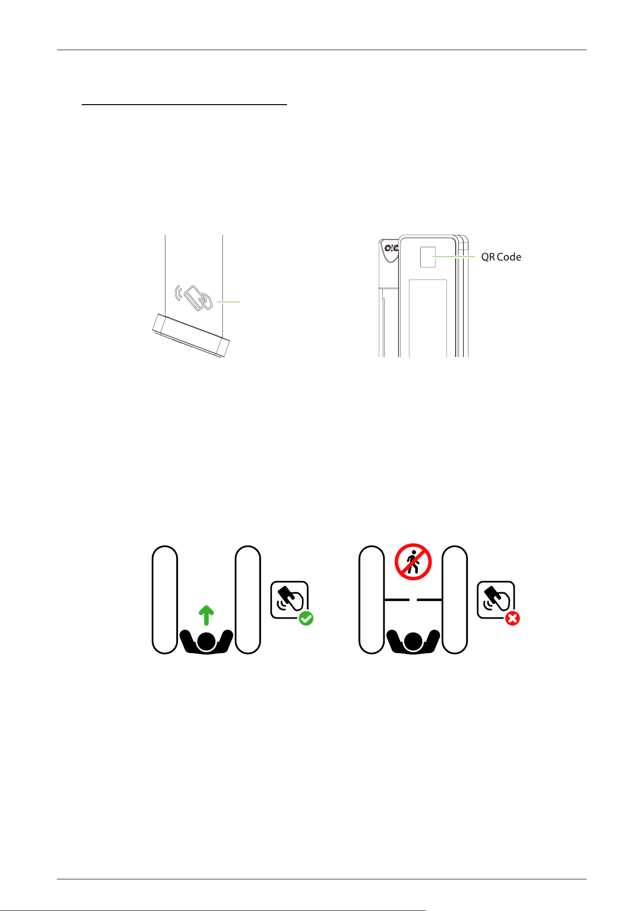
Card Verification 2.1
When the device is configured with a card reader module, the Card Verification mode compares the
card number in the card induction area with all of the card number data registered in the device and
sends it to the Access Controller.
When a user presses his / her card on the card reading area, the device enters card authentication
mode.
RFID
NO ENTRY
RFID
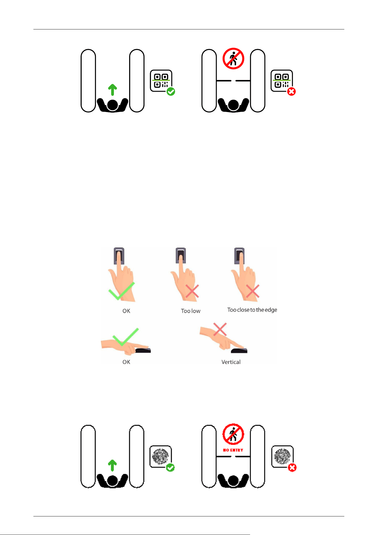
QR Code Verification 2.2
The QR code Verification mode is to scan the QR code on the user's mobile phone through the QR
code scanner and compare the data with the registered QR code, and then sends it to the Access
Controller.
When the user places the mobile phone displaying with the QR code on top of the QR code scanner,
the device enters the QR code authentication mode.
Card Reading Area or
Fingerprint Sensor
Saturn-S4000 Series User Manual
Page | 20 Copyright©2026 ZKTECO CO., LTD.All Rights Reserved.
NO ENTRY
Fingerprint Verification
★
2.3
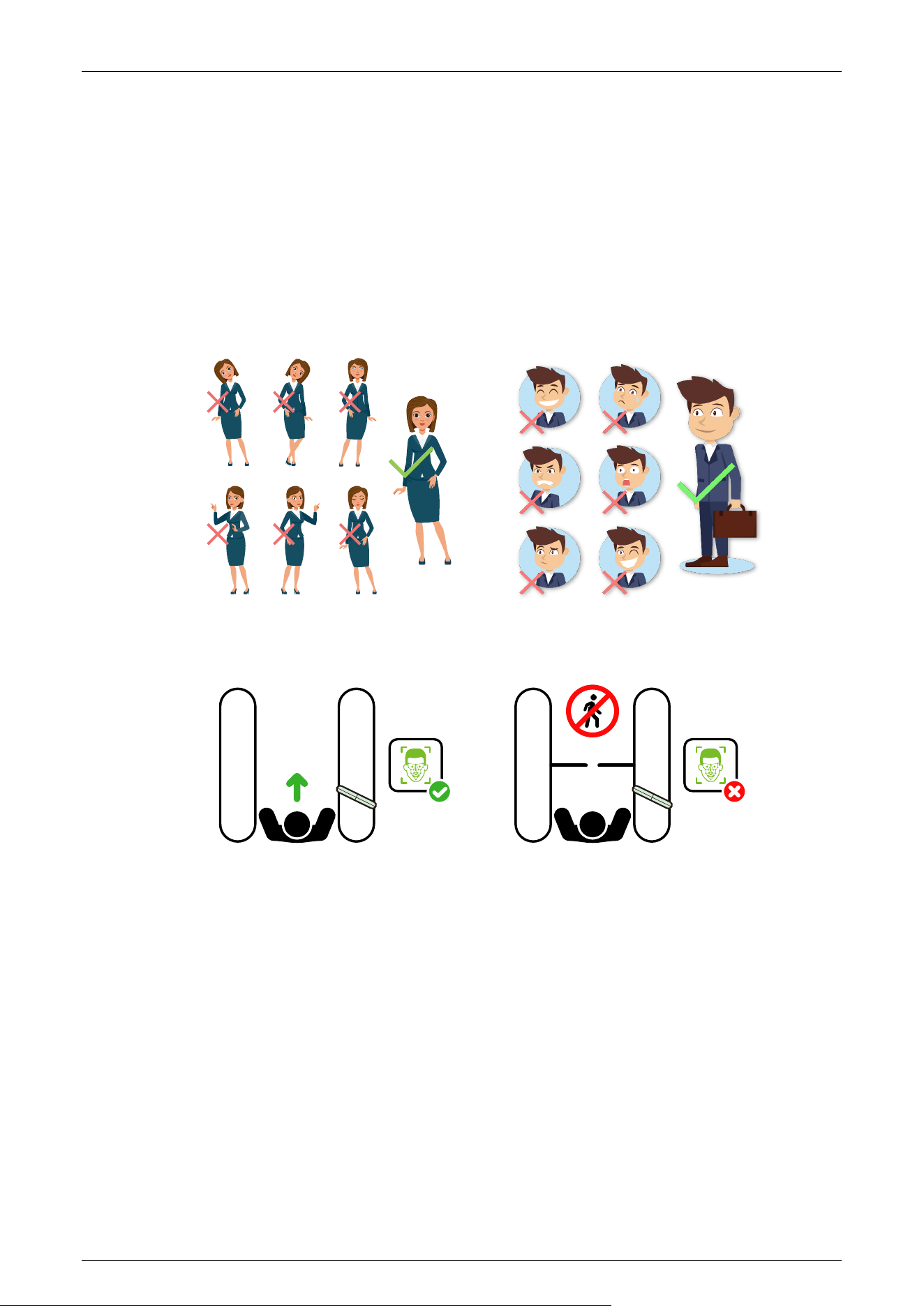
In this verification mode, the device compares the fingerprint that is being pressed onto the
fingerprint reader with all the fingerprint data sends it to the Access Controller.
The device enters the fingerprint authentication mode when a user presses his/her finger onto the
fingerprint scanner.
Recommended fingers: It is recommended to use index, middle, or ring finger for registration and
avoid using the thumb or little finger, as they are difficult to accurately press onto the fingerprint
reader.
Note: Please use the correct method when pressing your fingers onto the fingerprint reader for
registration and identification. Our company will assume no liability for recognition issues that may
result from incorrect usage of the product. We reserve the right of final interpretation and
modification concerning this point.
Saturn-S4000 Series User Manual
Page | 21 Copyright©2026 ZKTECO CO., LTD.All Rights Reserved.
Facial Verification
★
2.4
In this verification mode, the device compares the collected facial images with all face data
registered in the device and then sends it to the Access Controller.
Try to keep the face in the centre of the screen during authentication. Please face towards the
camera and stay still during face registration.
Recommended Standing Posture and Facial Expression:
Note: Please keep your facial expression and standing posture natural while enrollment or verification.
NO ENTRY

Saturn-S4000 Series User Manual
Page | 22 Copyright©2026 ZKTECO CO., LTD.All Rights Reserved.
3 Installation
Installation Tools 3.1
Tapeline
Marker Pen
Pencil
Percussion Drill
Screwdriver
Wrench
Hex Wrench
Cutting Machine
Installation Requirements 3.2
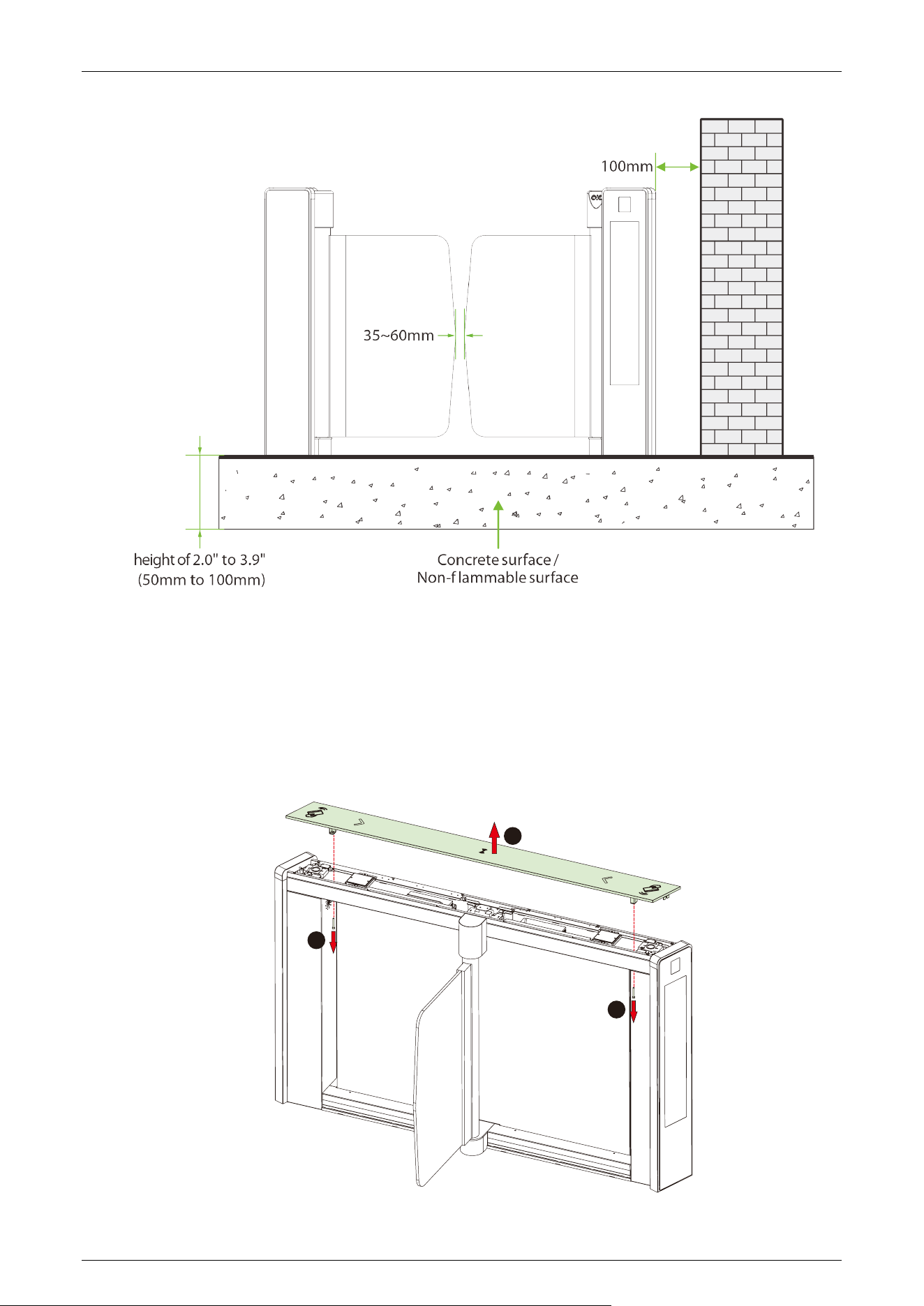
1. It is recommended that the turnstile must be installed on a horizontal solid platform with a height of
2.0" to 3.9"(50mm to 100mm).
2. It is recommended that the turnstile should not be used in the corrosive environment.
3. Make sure that the ground wire of the system is securely connected to avoid personal injuries or
other accidents.
4. After installation, check if the connection has been done correctly at the connecting points of
the ground wire, at the connector assemblies and wiring points of the circuits, as well as at each
movable part of the turnstile. Any loose nuts, screws and other fasteners should be tightened in
time to avoid any failures caused by long-time operations.
Installation Environment 3.3
1. Before installation begins, prepare installation tools, check the device and the accessories, and
clear the installation base.
2. Make sure that the appliance is mounted on a concrete surface or other non-flammable surfaces
surfaces.
3. The installation position of the turnstile depends on its size. A distance of 3.9"(100mm) between the
turnstile and the wall needs to be reserved for ease of opening the top lid of the turnstile to
perform maintenance and adjustment. The reference figure is shown below:
Saturn-S4000 Series User Manual
Page | 23 Copyright©2026 ZKTECO CO., LTD.All Rights Reserved.
Installation Cabinet 3.4
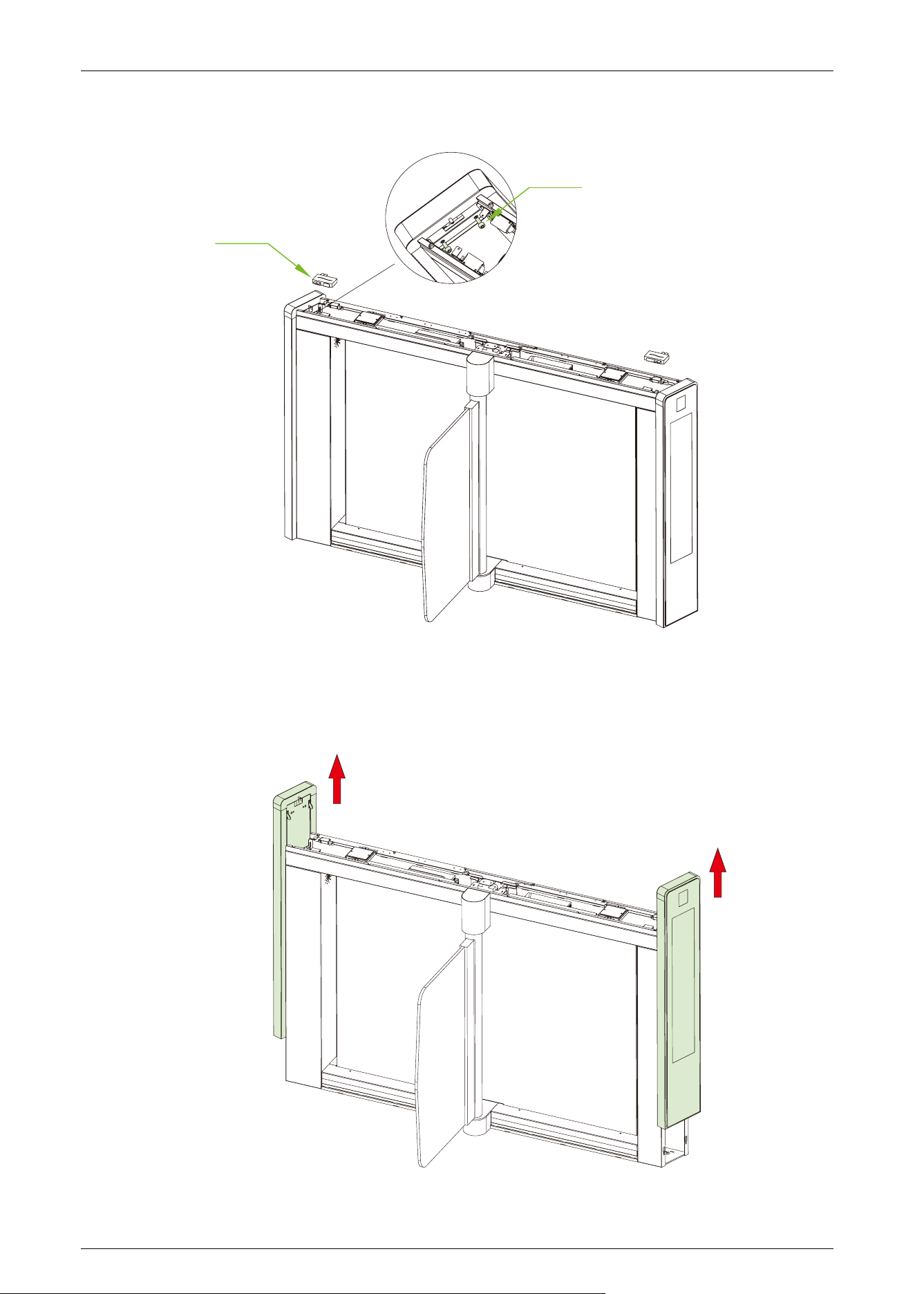
Step 1 Remove the Top Lid
1. Use a screwdriver to loosen the two fixing screws at the indicated locations, then remove the top lid in
the direction shown.
1
2
1
Saturn-S4000 Series User Manual
Page | 24 Copyright©2026 ZKTECO CO., LTD.All Rights Reserved.
2. Loosen the screws and the readers as shown in the figure below.
Reader
Screws
Step 2 Remove the Side Pedestal
1. Push the side pedestal on both sides upward and then remove them.
Note: LCD screen cable
Note: LCD screen cable
Saturn-S4000 Series User Manual
Page | 25 Copyright©2026 ZKTECO CO., LTD.All Rights Reserved.
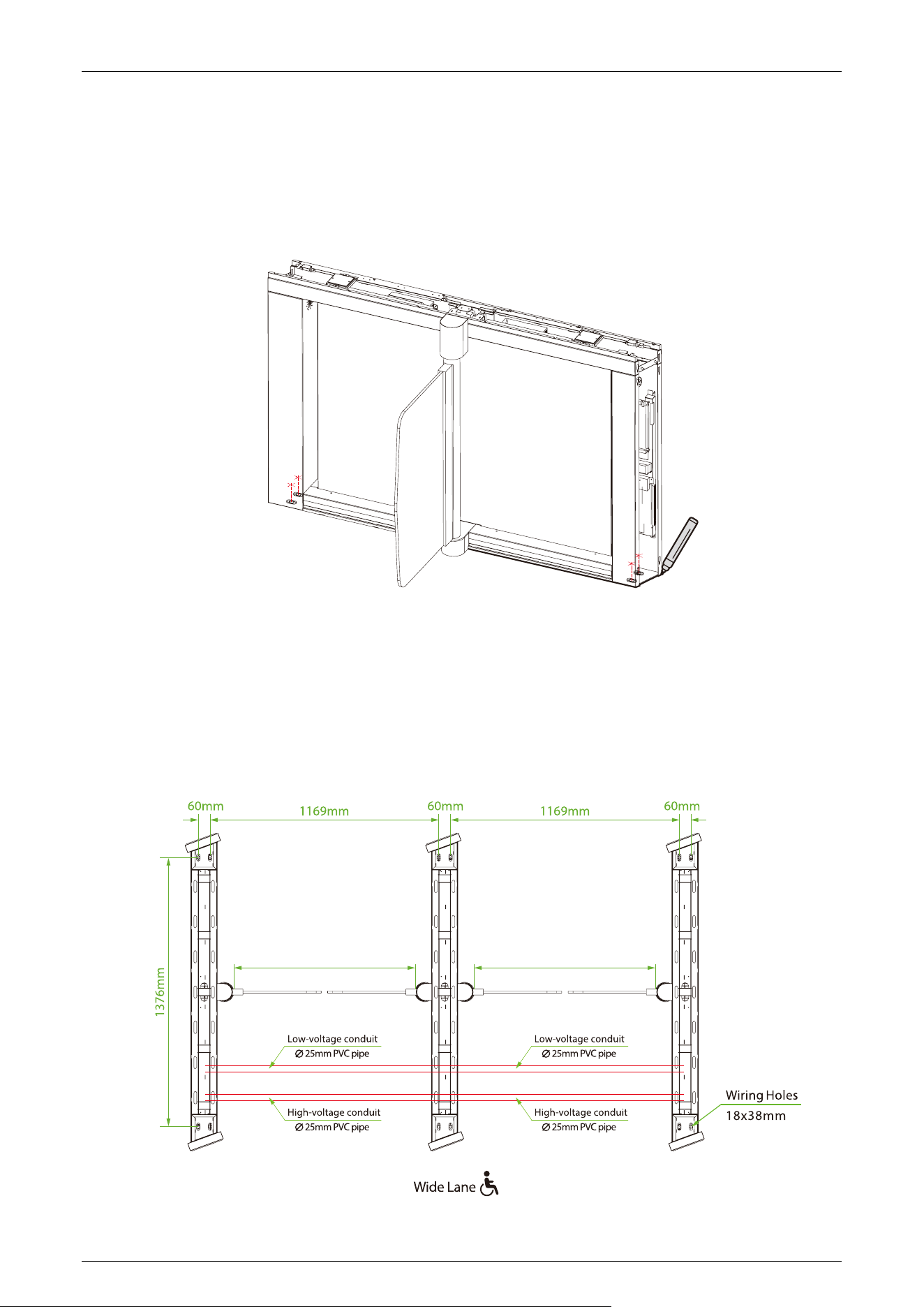
Step 3 Marker Position
1. Draw the location of the cabinet with a marker and mark each location of the mounting holes. There
will be a total of four mounting holes and two wire holes per cabinet.
2. Remove the cabinets when finished.
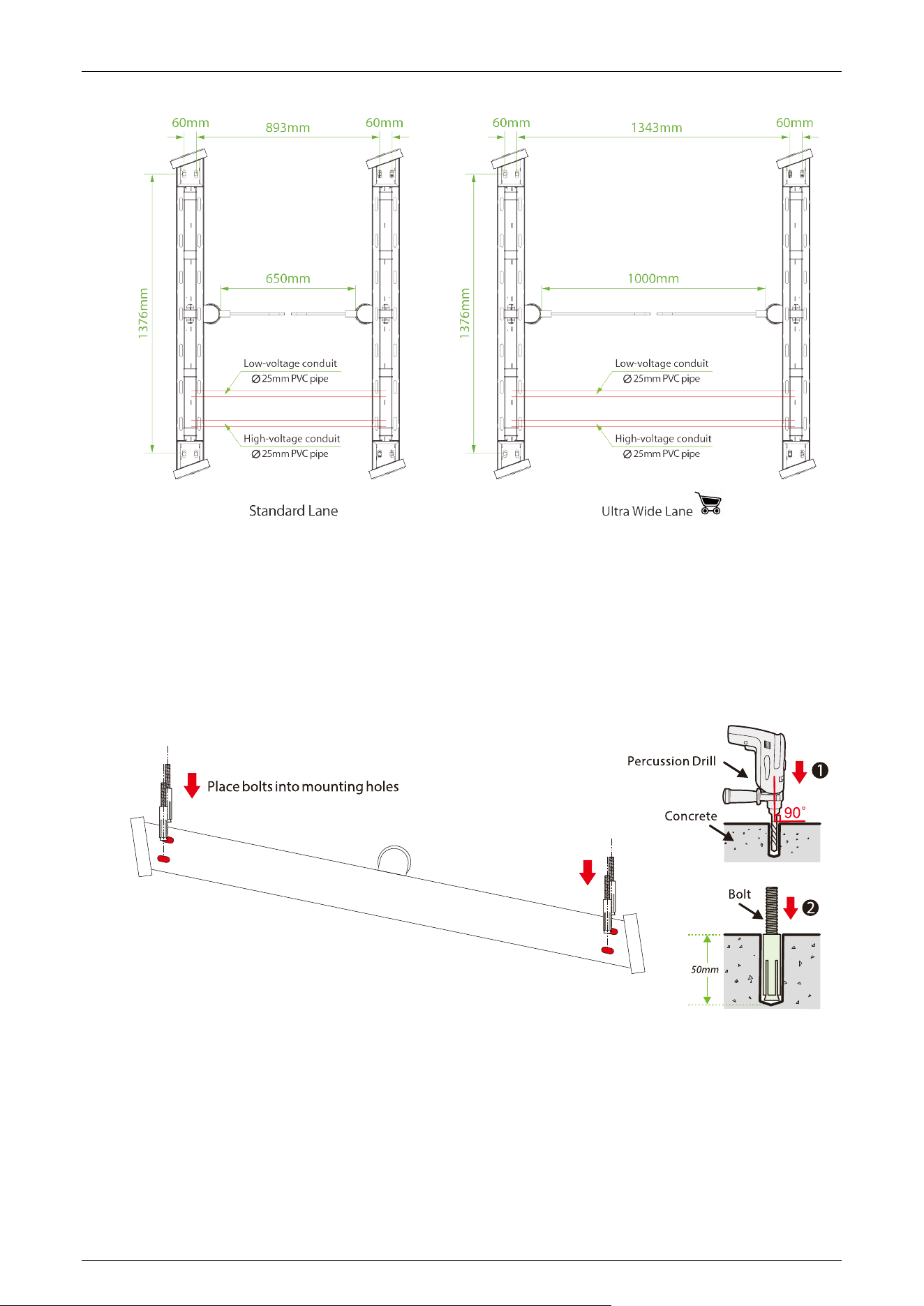
Step 4 Determine the Mounting Location
1. Please refer to the user's manual and complete the power-on self test operation before installation.
2. Then place the cabinet according to the mounting distances shown in the diagram below. Take care to
measure the distance between the bottom inside walls of the cabinets on the entrance side and exit
side of the channel and make sure that the measurements are consistent.
900mm
900mm
Saturn-S4000 Series User Manual
Page | 26 Copyright©2026 ZKTECO CO., LTD.All Rights Reserved.
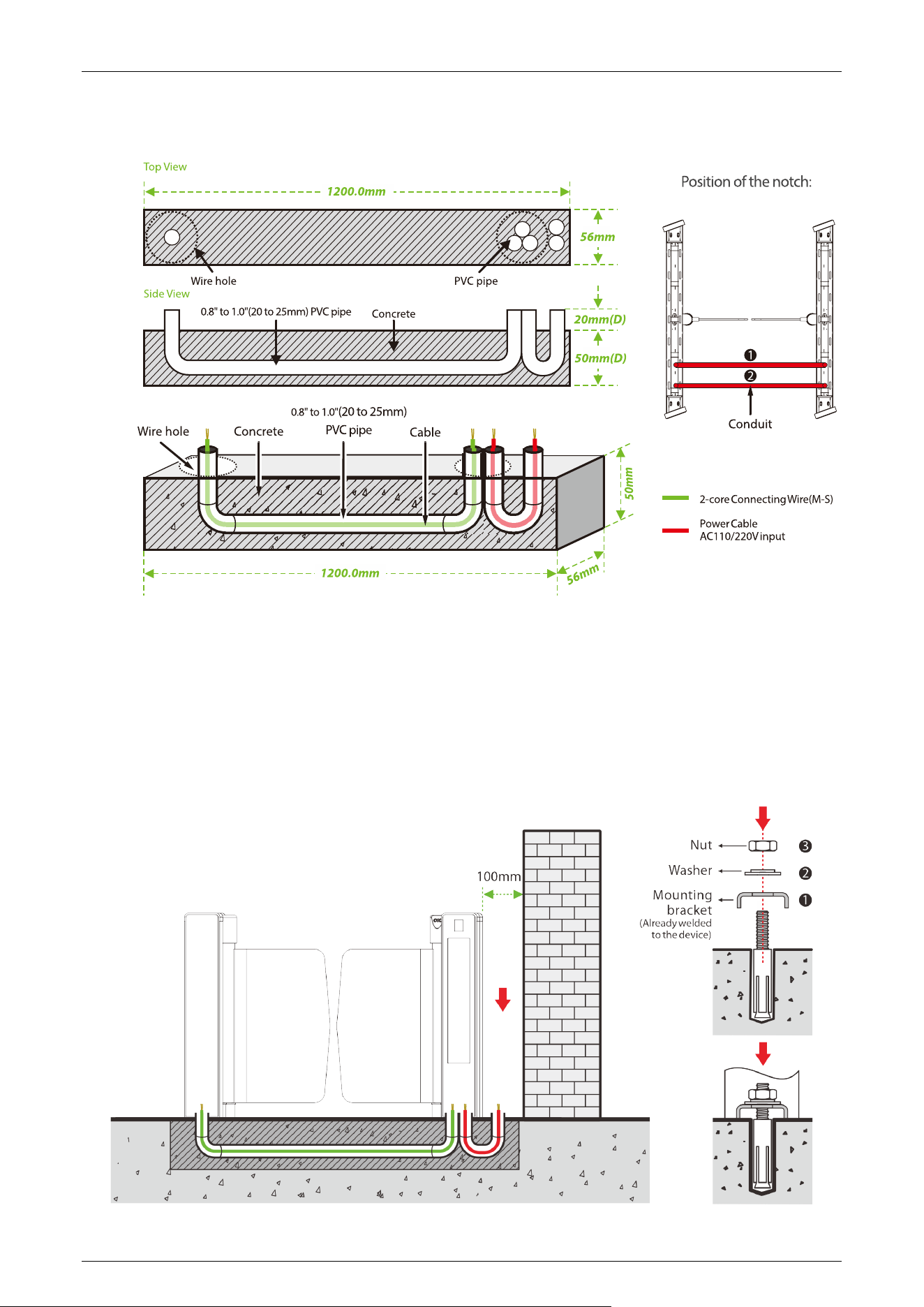
Step 5 Drill Holes and Place Bolts
1. Using a concrete drill bit, drill the mounting holes 2.0" (50mm) in depth at the center of each marked
location.
2. Then insert the bolts vertically into the mounting holes as shown at right.
3. Make sure the bolts are placed in place. Use a hammer to tap the bolts into place, if needed.
Step 6 Wireway Laying
1. Dig a recess of 2.0" (50mm) depth between the wire holes on both sides of the channel with the
dimensions shown below. Recesses can be dug at positions ❶ and ❷.
2. Then lay two 0.8" to 1.0" (20 to 25mm) diameter PVC pipes as shown below.
Saturn-S4000 Series User Manual
Page | 27 Copyright©2026 ZKTECO CO., LTD.All Rights Reserved.
3. After threading the cable out of the PVC pipe, pour concrete to f ix it in place.
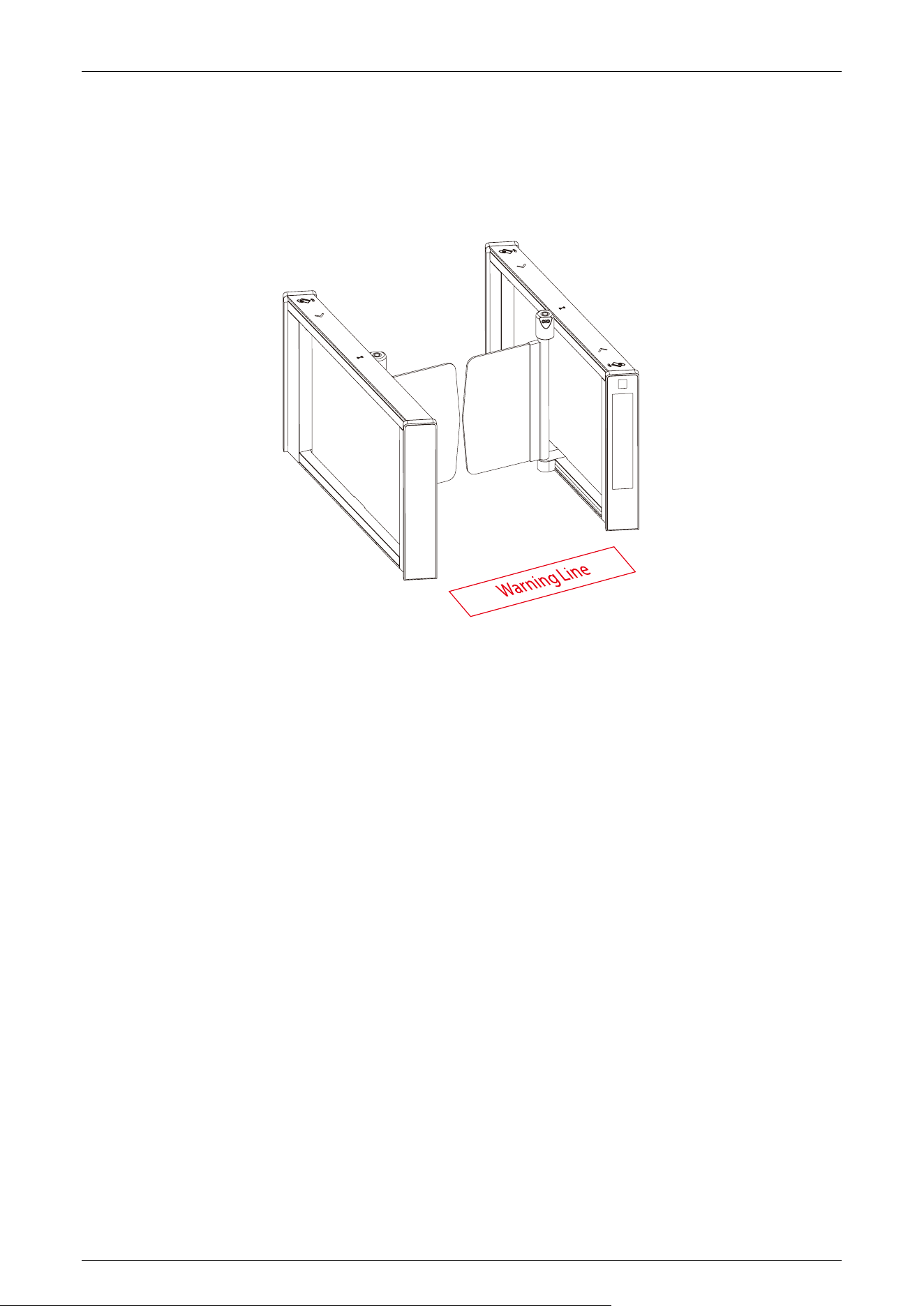
Step 7 Secure the Cabinet
1. After laying the PVC pipe, place the cabinet alignment bolts back into the mounting position.
2. Then insert the eight washers and nuts into the bolts one by one.
3. Tighten the nuts to hold the cabinet in place. Don't tighten it completely until after you're sure it won't
move anymore. The finished result is shown below:
Saturn-S4000 Series User Manual
Page | 28 Copyright©2026 ZKTECO CO., LTD.All Rights Reserved.
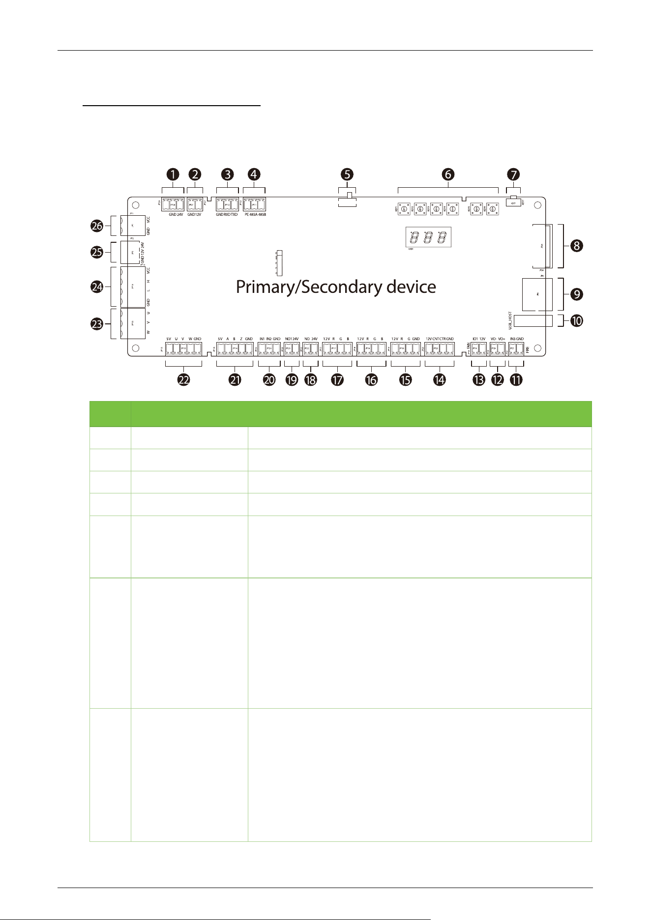
Step 8 Marking the Warning Line
1. It is recommended that warning lines be marked on the ground and used to alert users.
2. A warning line can alert users to wait outside the line until the previous user completes the verification
process and passes through the turnstile.
Saturn-S4000 Series User Manual
Page | 29 Copyright©2026 ZKTECO CO., LTD.All Rights Reserved.
4 Terminal Description
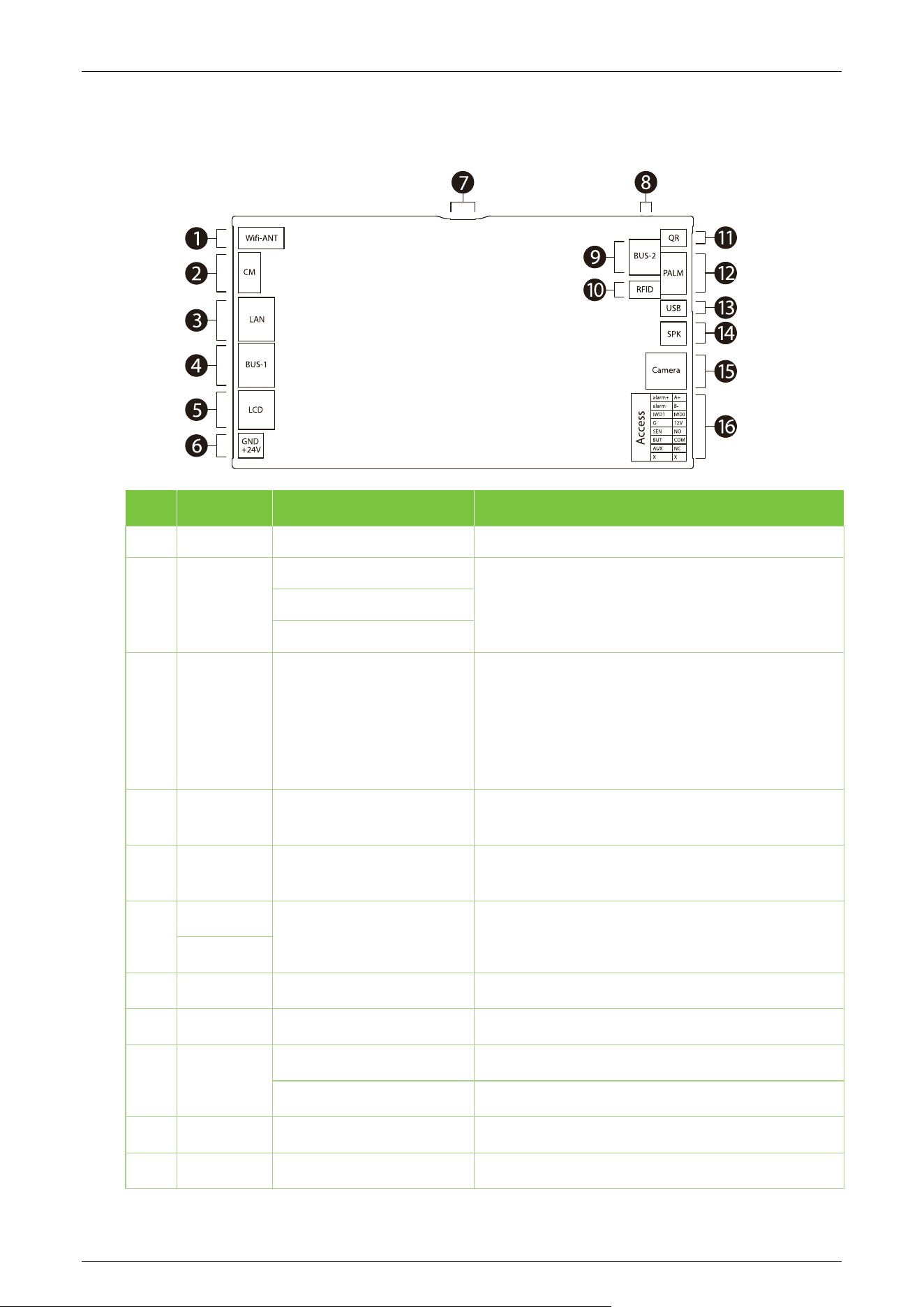
Primary and Secondary Board 4.1
NO. Terminal Descriptions
1 /, GND, 24V 24V DC power supply output
2 GND, 12V 12V DC power supply output
3 GND, RXD, TXD RS232 communication
4 GND, 485A, 485B RS485 communication
5 KEY8
DIP switch
Used to switch between the main and sub boards. When dialled to
1 it is the main board and when dialled to ON it is the sub device.
6 KEY1-6
Operation keys
KEY1: Return, exit menu
KEY2: Decrease the value until the lower limit
KEY3: Incremental value up to the upper limit
KEY4: Start menu/Confirm
KEY5: In
KEY6: Out
7 KEY7
KEY7: Restore Defaults / Reboot
1. Long press key KEY7 for more than 3 seconds to restore
default settings, short press for reboot.
If the firmware
changes affect menu items, you must restore defaults after the
update, then restart the main board.
2. The KEY7 button on the secondary unit is only for firmware
updates; it has no function in normal operation.

Saturn-S4000 Series User Manual
Page | 30 Copyright©2026 ZKTECO CO., LTD.All Rights Reserved.
8
Interface board infrared communication interface
9 / Network interface
10 USB_BOST
Program download port
Operation: Upgrade Firmware
a. Press and hold the KEY1 button continuously, then power off
and restart the device, or press the KEY7 button once.
b. At this time, the RUN light on the motherboard will slow down
its flashing, indicating that the device has entered the Program
Download Mode. You can now release the KEY1 button.
c. Then insert the USB drive containing the upgrade program. The
RUN light will flash rapidly. Once the rapid flashing ends and
returns to the normal flashing state, it indicates that the
upgrade has been successful. You can then remove the USB
drive. *Note: Do not remove the USB drive during the upgrade
process.*
11 IN3, GND Fire interface
12 VO-, VO+ Speaker
13 GND, 12V Fan
14 12V, CNT, CLR, GND Counter
15 12V, R, G, GND Dot Matrix Board LED
16 12V, R, G, B Traffic Indicator
17 12V, R, G, B Visual Indicator
18 NO, 24V Clutch / Push-pull solenoid 1
19 NO1, 24V Push-pull solenoid 2
20 IN1, IN2, GND Door opening signal input
21 IN1, IN2, GND Encoder Interface
22 5V, A, B, Z, GND Hall interface
23 5V, U, V, W, GND Motor cable interface
24 U, V, W Over machine communication line
25 24V, H, L, GND Super capacitor input
26 24V, 12V, GND Power input
8
7
6
5
4
3
2
1
GND
12V
16
15
14
13
12
11
10
9
GND
12V
Upper layer Lo wer layer
Saturn-S4000 Series User Manual
Page | 31 Copyright©2026 ZKTECO CO., LTD.All Rights Reserved.
Access Control Module
★
4.2
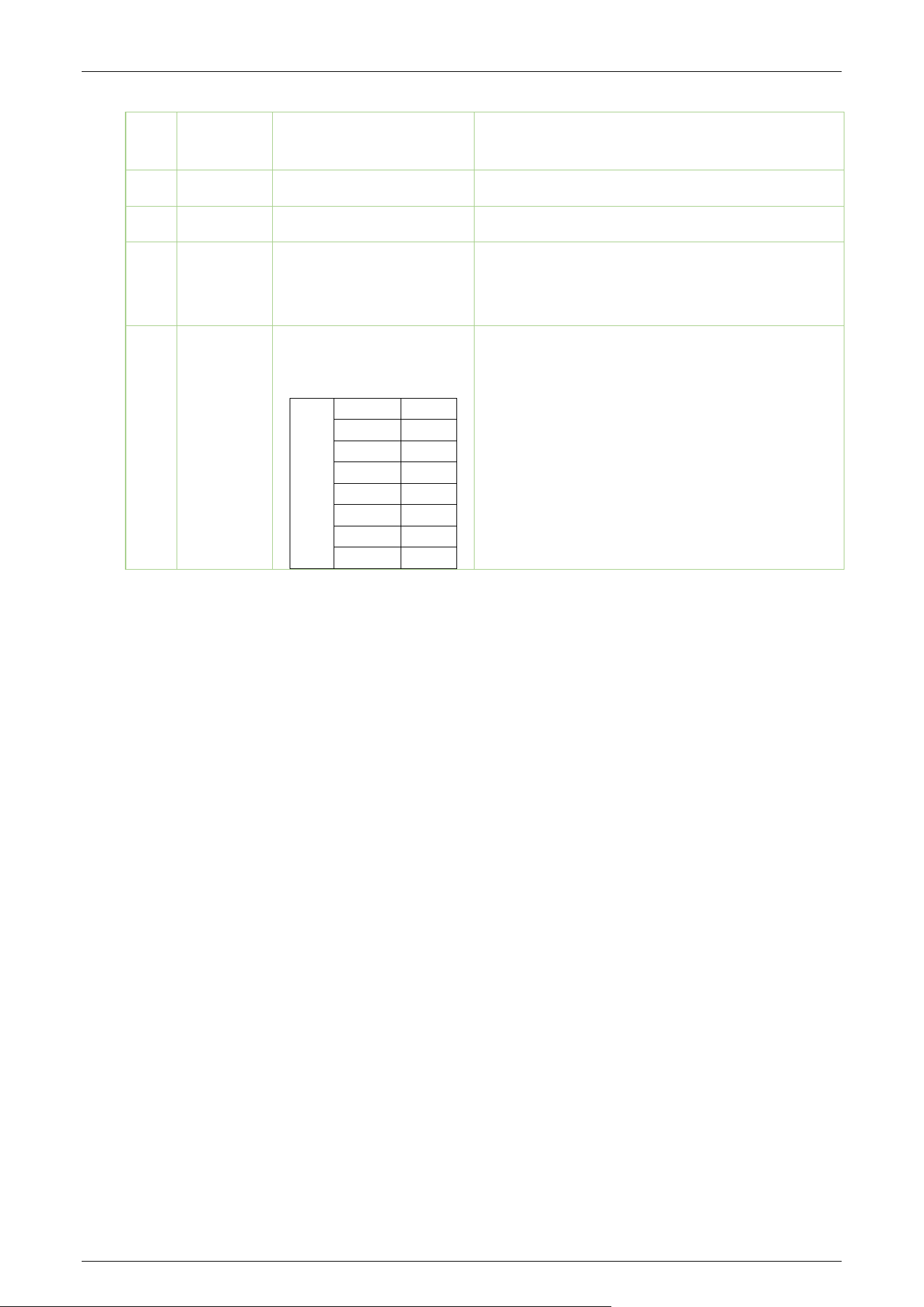
No. Terminals Descriptions Functional Description
1
Wi-Fi ANT Wi-Fi Antenna Connect the Wi-Fi antenna.
2
CM
Verification Tip Light
The camera connected to the facial recognition
module.
NFC
Camera Fill Light
3
LAN Network
RJ45, Yellow holder
The default device IP address is: 192.168.1.201
Note: In LAN, IP addresses of the server (PC) and
the device must be in the same network segment
when connecting to the software.
4
BUS-1 Synchronised LAN
Networking, synchronising main and sub devices
RJ45, Blue holder
5
LCD LCD display module Used to connect the 7’’ LCD display module.
6
GND
Power Input 24V DC power supply input
+24V
7
MicroUSB Burn-in Port
8
RESET Reset For resetting account password, IP address
9
BUS-2
485-1 Connecting gate control board
485-2 Synchronous sub device
10
RFID RFID recognition module Used to connect the RFID recognition module.
11
QR QR code reader module Used to connect the QR code reader module
Saturn-S4000 Series User Manual
Page | 32 Copyright©2026 ZKTECO CO., LTD.All Rights Reserved.
12
PALM Palm recognition module
Used to connect the palm recognition module
(optional).
13
USB USB Reservation
14
SPK Speaker To play alarms or alert voices.
15
Camera
Camera /
Facial recognition
module
Used to connect the camera.
Can be docked to the camera of the facial
recognition module. MIPI Port
16
Access
Access
alarm+
A+
alarm-
B-
IWD1
IWD0
G
12V
SEN
NO
BUT
COM
AUX
NC
X
X
Used to connect the reader, Access control all-in-
one machine. And the relay can be connected
directly to the gate control board.
Included:
2 pcs Relays
1 pc 485
1 pc Wiegand input
3 pcs Auxiliary inputs
Saturn-S4000 Series User Manual
Page | 33 Copyright©2026 ZKTECO CO., LTD.All Rights Reserved.
5 Wiring Instructions
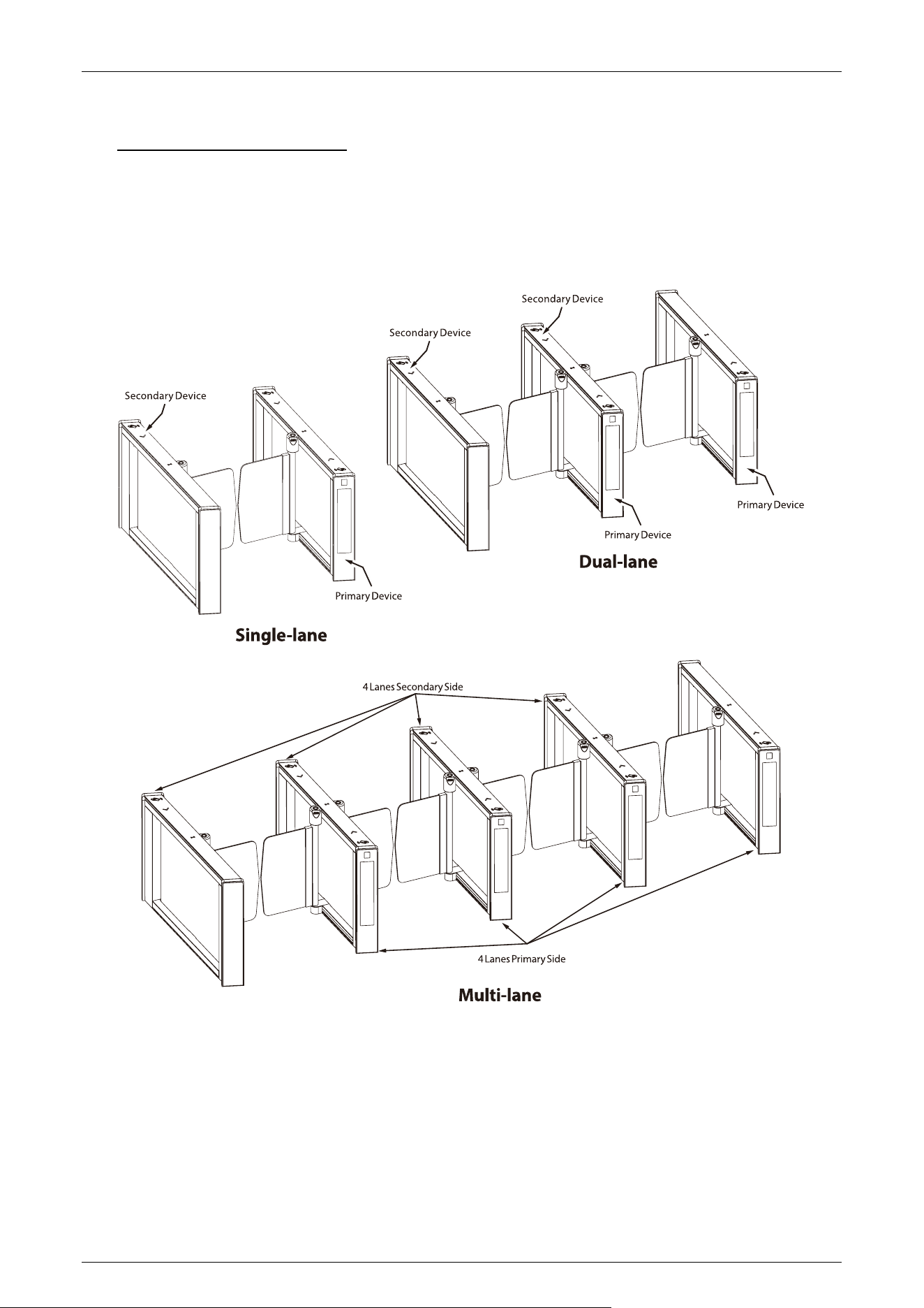
Primary and Secondary Location 5.1
The positions of the primary and secondary corresponding to single-lane, dual-lane and multi-lane
are shown in the figure below.
Saturn-S4000 Series User Manual
Page | 34 Copyright©2026 ZKTECO CO., LTD.All Rights Reserved.
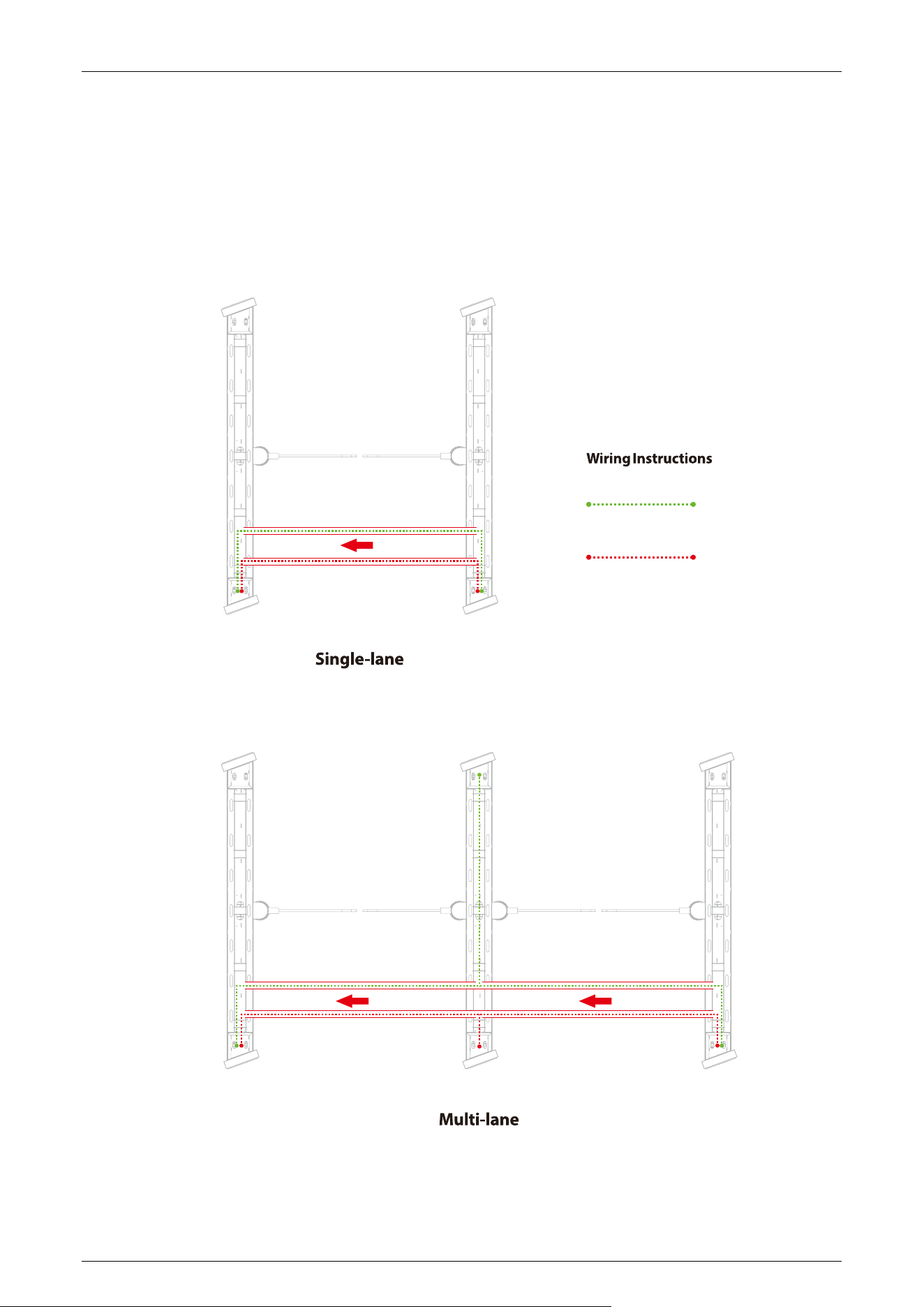
Wiring Methods 5.2
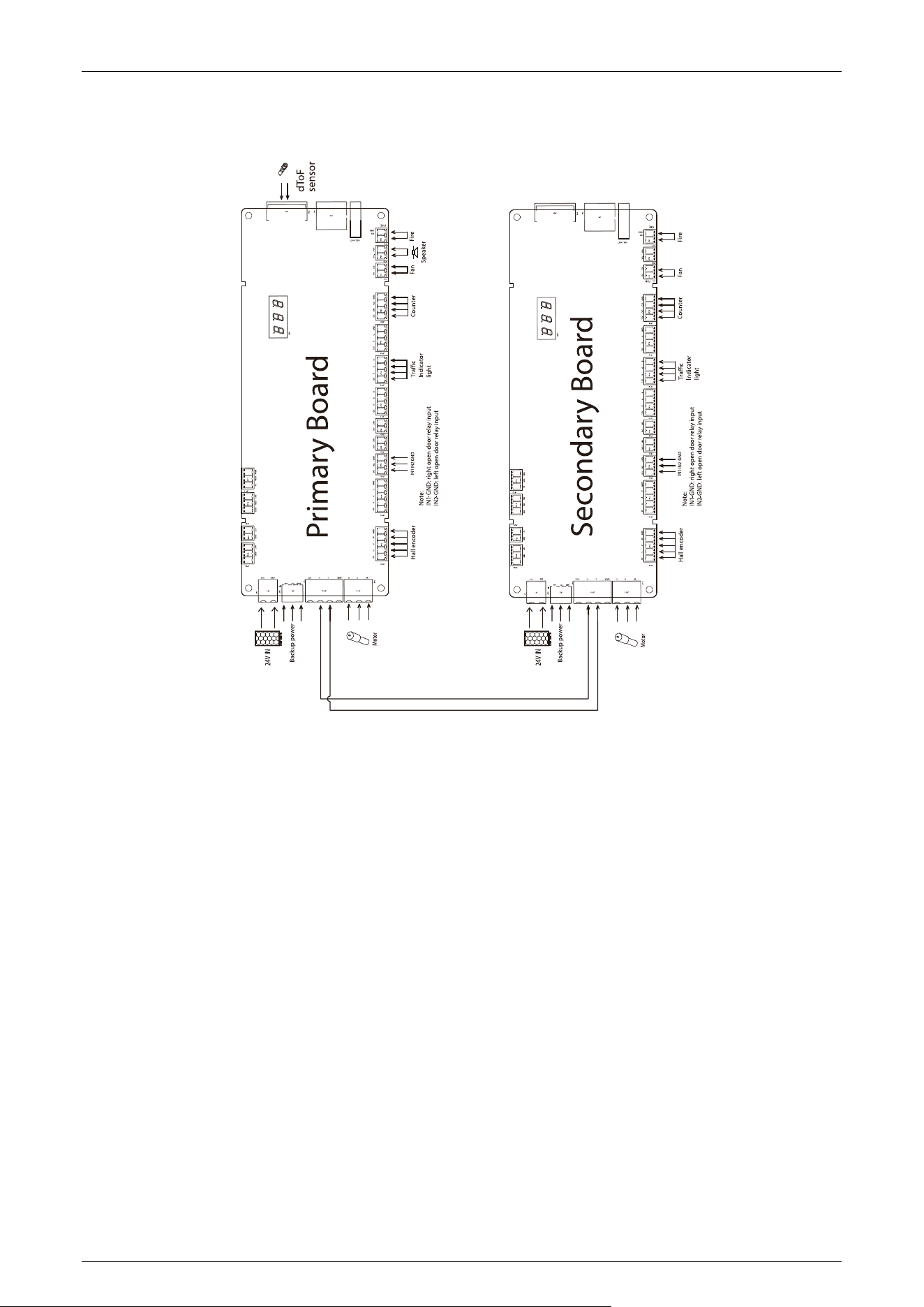
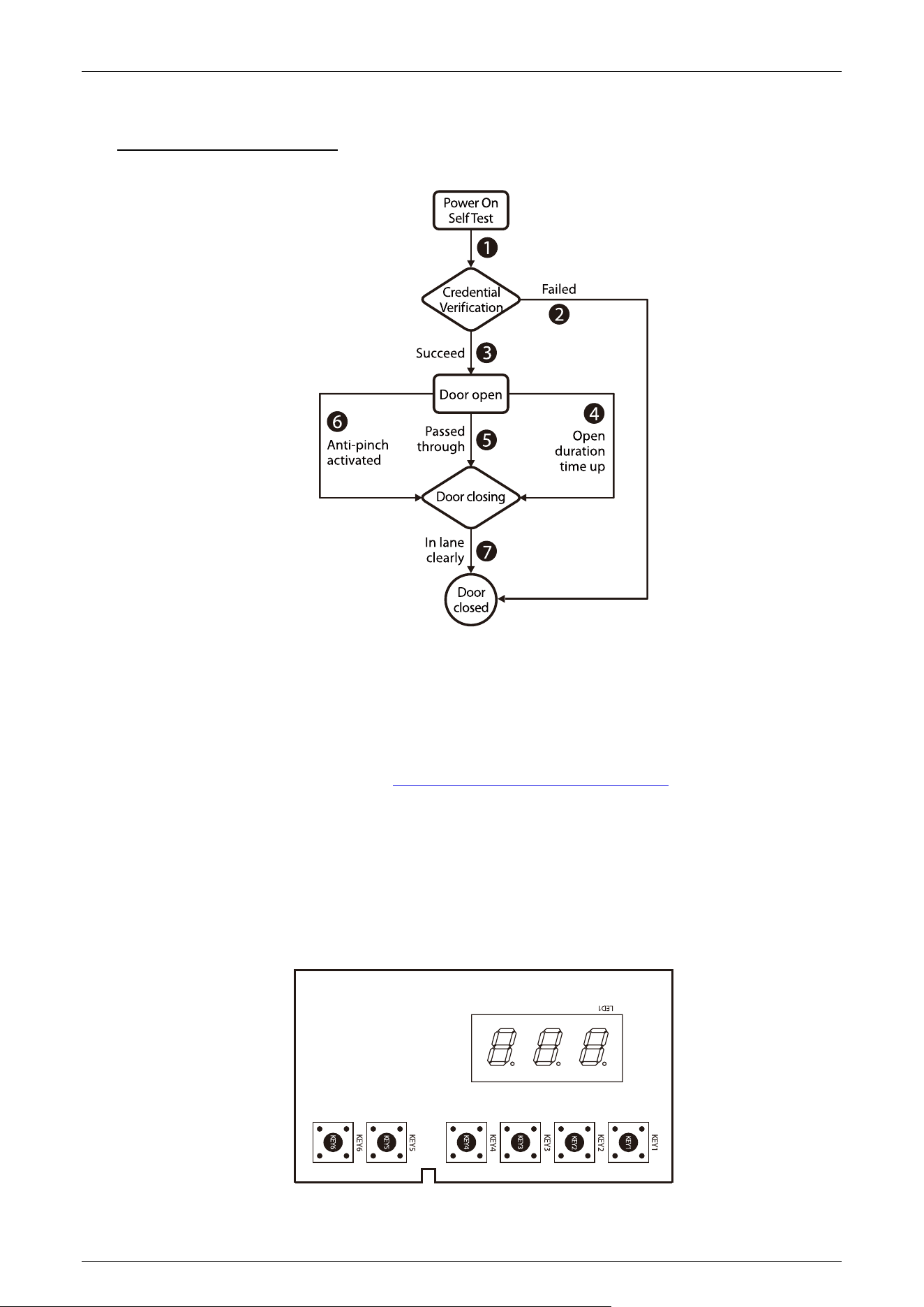
The wiring principle is to connect the main device to the sub device and communicate via the ECU-
panel connection wire. Each main device is then powered individually. The following diagram shows
how the different channels are wired.
2-core connecting wire(M-S)
Secondary device
Primary device
Secondary device Secondary device
Primary device Primary device
Power Cable AC110/220V input
Saturn-S4000 Series User Manual
Page | 35 Copyright©2026 ZKTECO CO., LTD.All Rights Reserved.
Power and Circuit Breaker Wiring 5.3
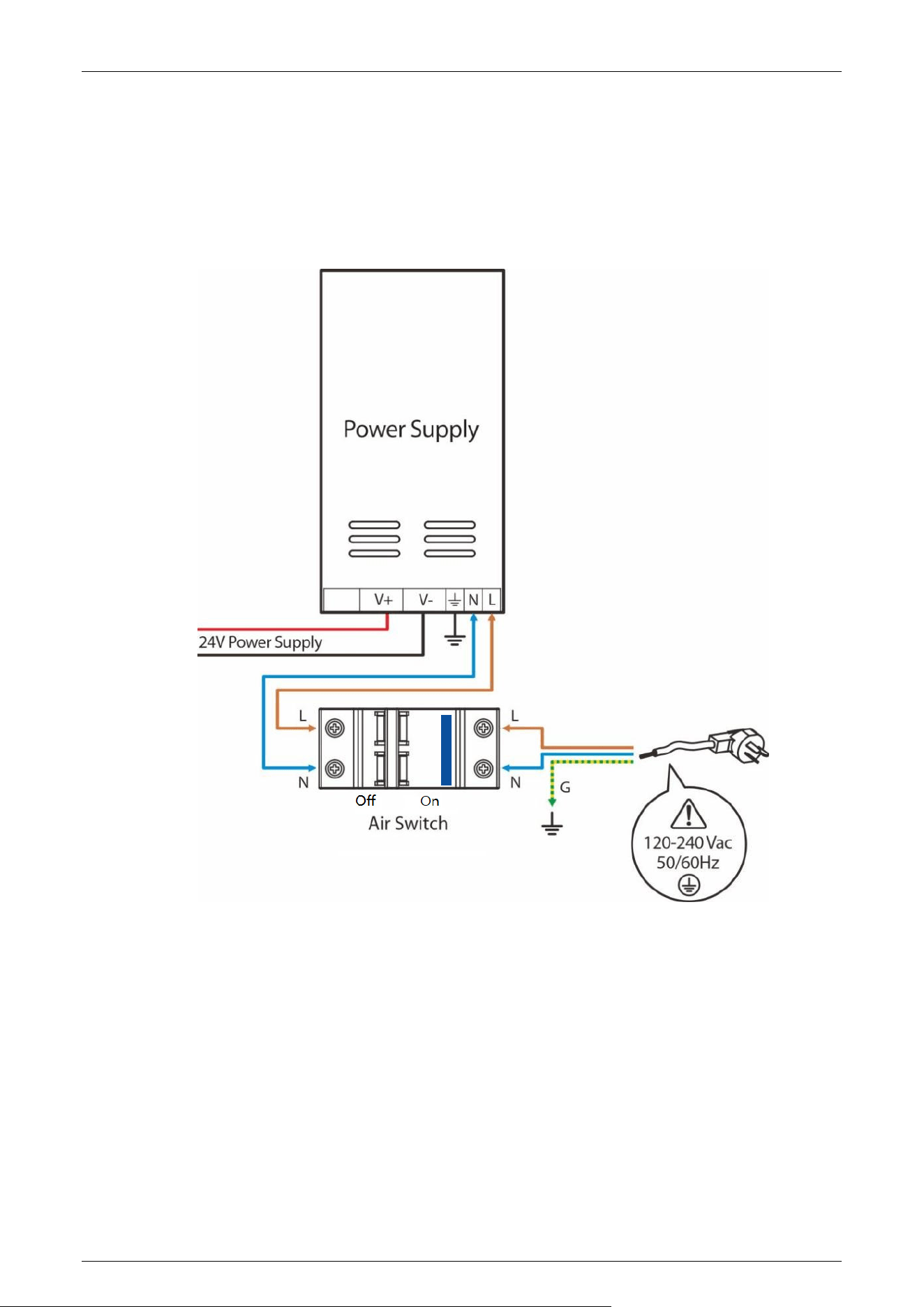
120Vac and 240Vac primary power must be hard wired in place (Note: must be grounded). It is
strongly recommended that a licensed electrician perform this procedure in accordance with
applicable local codes.
Saturn-S4000 Series User Manual
Page | 36 Copyright©2026 ZKTECO CO., LTD.All Rights Reserved.
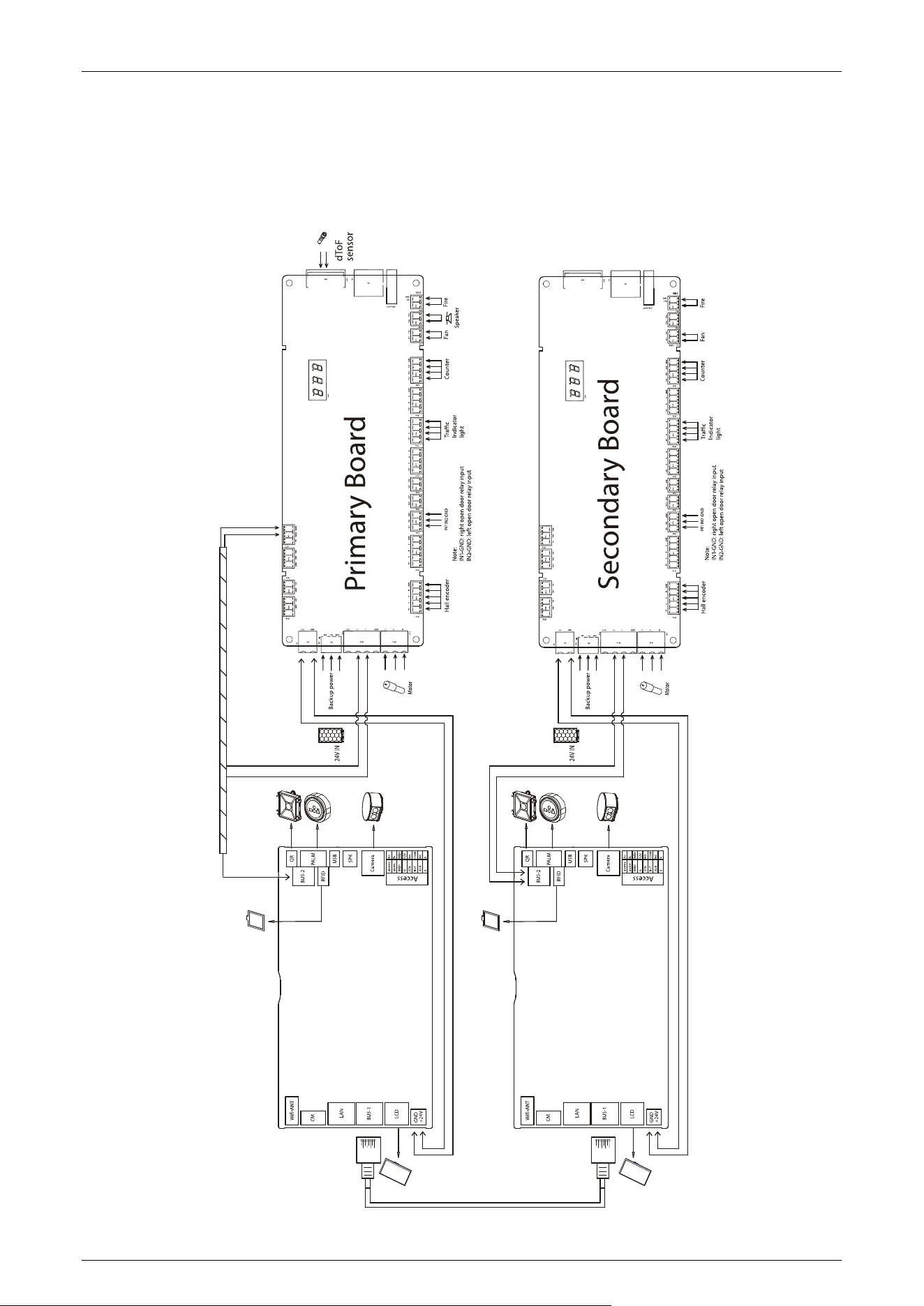
System Wiring Diagram 5.4
Multimodal + dToF Sensor Version
Saturn-S4000 Series User Manual
Page | 37 Copyright©2026 ZKTECO CO., LTD.All Rights Reserved.
dToF Sensor Standard Version
Saturn-S4000 Series User Manual
Page | 38 Copyright©2026 ZKTECO CO., LTD.All Rights Reserved.
6 Operation Process
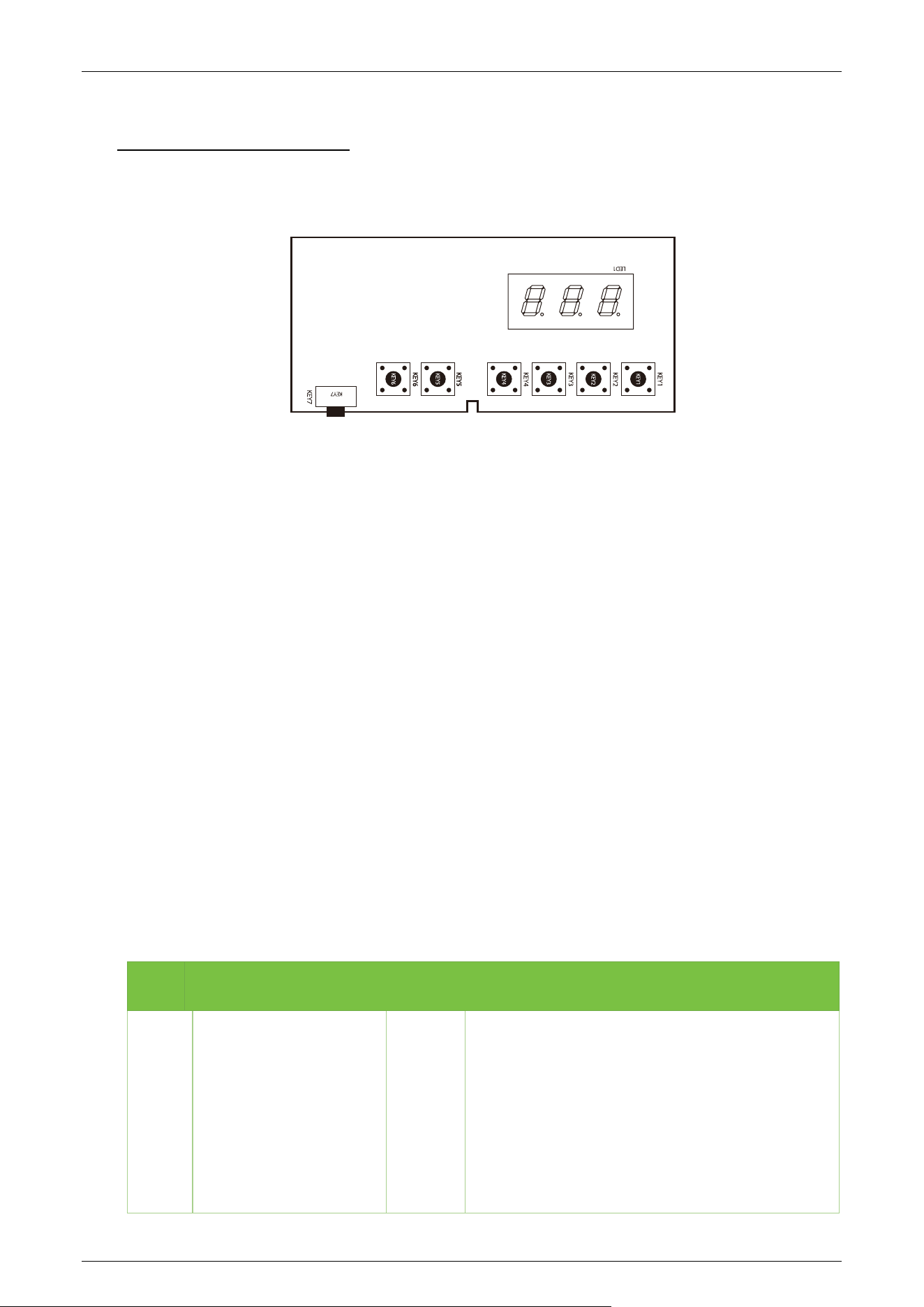
1. POST (Power On Self Test)
When powering up the unit, wait 30 seconds for the system to perform a POST (Power On Self Test)
procedure. If no problems are detected, the unit will operate normally. If a fault is detected, the
system will display a relevant message on the LCD display so that the user can quickly understand
and solve the problem. (Reference 5.3 Power and Circuit Breaker Wiring
for connecting the air
switch and power supply.)
2. Credential Verification
After the unit's power on self test is complete, you can test the door opening by pressing the KEY 5/
KEY 6 button on the motherboard.

Saturn-S4000 Series User Manual
Page | 39 Copyright©2026 ZKTECO CO., LTD.All Rights Reserved.
When the user presses the KEY 5/ KEY 6 button on the main board, it is equivalent to recognizing a
valid card. The LCD display will show success and a buzzer will give a positive audible indication to
the pedestrian that it has been successfully validated. The card reader then sends a signal to the
access controller requesting permission to pass through the channel. The access controller will send
a signal to the revolving door control panel. After receiving the signal from the card reader and the
Infrared Sensor, the Turnstile Control Board will send valid control signals to the servo motor driver.
1) Verification Success
When the verification is successful, the door is opened.
2) Validation Failure
When verification fails, the door remains closed.
Note: At this time, if the system is in forbidden passing mode, the mode indicator light will turn red,
and the Turnstile Control Board will not accept signals of card.
3. Passed Through
After the passenger passes the channel according to the opening direction of the swing arm, the
Infrared Sensor will keep detecting the movement of the pedestrian throughout the passage and
continue to deliver signals to the Turnstile Control Board until the pedestrian passes through the
passage.
If the pedestrian enters without ID or an invalid card, the system will prompt an audible alarm. The
alarm signal will not be canceled until the passenger retreats from the passage. The pedestrian can
pass through the passage only after a valid card is successfully verified.
Saturn-S4000 Series User Manual
Page | 40 Copyright©2026 ZKTECO CO., LTD.All Rights Reserved.
7 Machine Operation
Operation Buttons Description 7.1
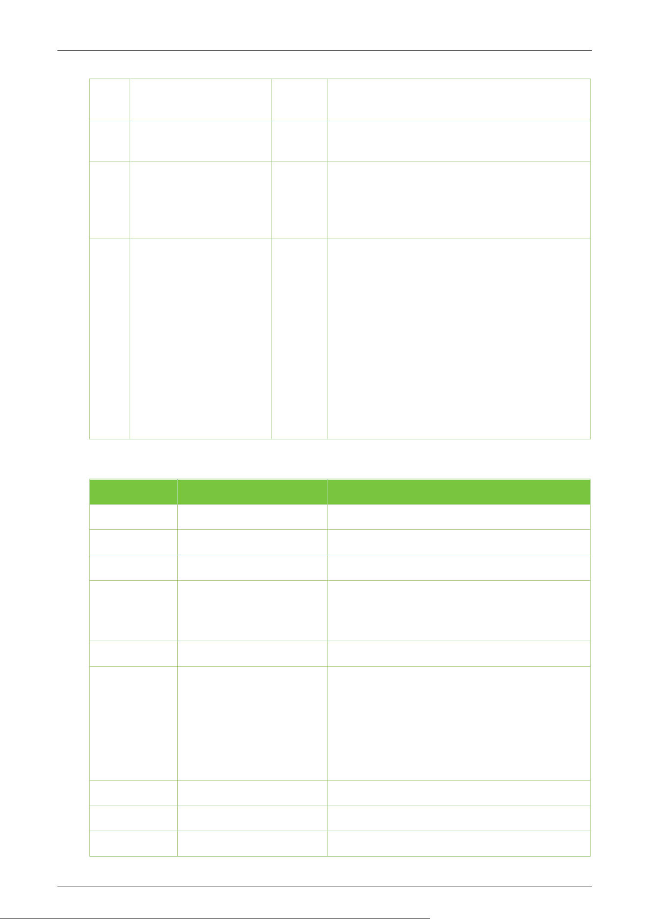
There are six menu operation buttons on the primary/secondary board.
Operation Buttons Description:
KEY1: Return / Exit menu
KEY2: Decrease the value until the lower limit
KEY3: Incremental value up to the upper limit
KEY4: Start menu/Confirm
KEY5: In
KEY6: Out
KEY7: Restore Defaults/Reboot
Notes:
1. Long press key KEY7 for more than 3 seconds to restore default settings, short press for
reboot. If the firmware changes affect menu items, you must restore defaults after the update,
then restart the main board.
2. The KEY7 button on the secondary unit is only for firmware updates; it has no function in
normal operation.
Menu Parameter Settings 7.2
Code Parameter Definition
Default
Value
Range Value
C01
Motor Type 0
0: Null Type
1: GPG
2: BUE-1.25.037.400
3: LINIX
4: LINIX High Temperature
5: LINIX Low Temperature
6: X (Note: Option 6 has not yet been officially
activated.)

Saturn-S4000 Series User Manual
Page | 41 Copyright©2026 ZKTECO CO., LTD.All Rights Reserved.
C02
Lane Width Settings 2
1: 600 to 700
2: 800 to 900
3: 1000 to 1200
4: Auto Adjust
Note: When selecting automatic adjustment,
initialization defaults to starting from the first
item. If initialization fails, the system automatically
restarts and switches to the next item. Upon
successful initialization, the configuration is saved.
(If initialization fails, wait 3 minutes before
restarting.)
C03
Sensor Type 1
1: Through-beam infrared
2: Diffuse reflection radar
C04
Number of Sensors 12
0 to 32
Note: The number of sensors must be manually
selected and confirmed (currently only supports
logic for 12 sensor pairs).
When using a cylindrical swing gate, set the
sensor count to 0.
C05
Set Door Closing Position
0
0: Ignore
1: Effective
C06
Set Right Door Opening
Position
0
0: Ignore
1: Effective
C07
Set Left Door Opening
Position
0
0: Ignore
1: Effective
C08
Aging Test
0
0: Exit
1: Enable
C09
Fan 1
0: Close
1: Open

Saturn-S4000 Series User Manual
Page | 42 Copyright©2026 ZKTECO CO., LTD.All Rights Reserved.
C10
Passage Mode 1
1: Entry authorized, exit authorized
2: Entry authorized, exit free
3: Entry free, exit authorized
4: Entry free, exit free
5: Entry authorized, exit prohibited
6: Entry prohibited, exit authorized
7: Entry free, exit prohibited
8: Entry prohibited, exit free
9: Entry prohibited, exit prohibited
10: Right always open
11: Left always open
12: Entry peak, exit authorized
13: Entry peak, exit free
14: Entry peak, exit prohibited
15: Entry authorized, exit peak
16: Entry free, exit peak
17: Entry prohibited, exit peak
Note: In peak mode, it automatically switches to
non-pinch mode at the beginning and end.
C11
Memory Gate Opening 0
0: Off
1: On
C12
Verify Regional Settings 0
0: in-channel authentication is allowed
1: in-channel validation not allowed
C13
Set Door Opening Speed 100 0 to 100
C14
Set Door Closing Speed 100 0 to 100
C15
Passage Timeout 5 2 to 60 seconds
C16
Door Closing Delay 0 0 to 60 seconds
C17
Dwell Time 10 5 to 60 seconds, default 10 seconds
C18
Electric Lock Type 1
0: No lock
1: Clutch
2: Electromagnet
C19
Reverse Intrusion Setting 1
0: Alarm on Door Closure
1: Alarm
2: Ignore
Note: When C19 is set to 0, it will automatically
switch to non-squeeze mode at the beginning
and end.

Saturn-S4000 Series User Manual
Page | 43 Copyright©2026 ZKTECO CO., LTD.All Rights Reserved.
C20
Tailgating Setting 1
0: Alarm on Door Closure
1: Alarm
2: Ignore
Note: When C20 is set to 0, it automatically
switches to non-pinch mode at the beginning and
end.
C21
Anti-Pinch Setting 0
0: Flap stops
1: Flap stops and reverses to open
2: Ignore
Note:
a. When parameter C19 or C20 is set to 0, the
reverse opening function of anti-pinch setting
option 1 is invalid.
b. When the parameter is set to 1, during the door
closing process, if a pedestrian enters from the
opposite direction, triggering the anti-pinch
function will only stop the door without
opening it to avoid causing injury.
C22
Anti-pinch Zone 0
0: All Infrared
1: Excluding First and Last Infrared
C23
Fire Mode 0
0: Open Right Door
1: Open Left Door
2: Ignore
C24
Door Closing Mode 0
0: Close the door after exiting the lane
1: Close the door after passing through the anti-
pinch zone
Note: The C22 settings must be modified
accordingly.
C25
Alarm Sound Setting 1
0: Close
1: Open
C26
Voice Switching 1
0: Voice Announcement
1: Alert Tone
C27
Voice Volume 80 0 to 100
C28
Inbound Voice 0 0 to 30
C29
Outbound Voice 17 0 to 30
Saturn-S4000 Series User Manual
Page | 44 Copyright©2026 ZKTECO CO., LTD.All Rights Reserved.
C30
Inbound Passage Count
Reset
0
0: No
1: Yes
C31
Outbound Passage Count
Reset
0
0: No
1: Yes
C32
Developer Mode 0
0: No
1: Yes (Ignore, used for obtaining exception data)
Note: Used to obtain exception feedback data
C33
Turnstile Type 0
0: None
1: Bridge Swing Gate
2: Single Swing Gate/Cylindrical Swing Gate
Note: The entry and exit directions of the dual
swing gate connect to separate mode lights and
passage indicator lights respectively;
The entry and exit directions of the single swing
gate share the passage indicator light JP17, while
the entry/exit mode lights connect to JP18 and
JP19.
Error code Instruction Solution
E00
Sensor type error
E01
Radar quantity error
E02
Radar ranging anomaly
E03
CAN communication
anomaly
Check for poor contact at the connecting wire
terminals or verify that the secondary device is
receiving power.
E04
Motor type error
E05
Motor zeroing anomaly
Lane Width Settings
C01 (Select 03 for Saturn-
S2000/2200, Select 02
for Saturn-S4000/4200)
C02 Select 01, Change to 03
For on-site dual-
core installation, refer to the
manual and rotate 180 degrees.
E06
Turnstile type error
Er0
Unauthorized entry
Er1
Reverse passage

Saturn-S4000 Series User Manual
Page | 45 Copyright©2026 ZKTECO CO., LTD.All Rights Reserved.
Er2
Tailgating
Er3
Timeout without passage
Er4
Stalled
ST
Self-checking in progress
PO
Power loss
FF
Fire alarm activation
AT
Aging test initiated
Saturn-S4000 Series User Manual
Page | 46 Copyright©2026 ZKTECO CO., LTD.All Rights Reserved.
8 LCD Advertising Screen Operating Instructions
Digital Signage App Installation Guide 8.1
1. First, configure the device's network. Enter the Main Menu interface, click [Device] - [System
Settings] - [Connect to Network] (either WiFi or wired network is acceptable; the network must
have external internet access).
2. Install the APK on the digital signage device via USB drive: (i) Copy the APK file to a USB drive on
a computer. (ii) Insert the USB drive into the device. (iii) Navigate to the file manager and locate
the APK file. (iv) Execute the installation.
3. After installing the APK, open the application (ZKDigimax CMS). The home screen displays the
device name, serial number, network IP, and system information. (Please verify that all
information is correct before proceeding.)
CMS System User Guide 8.2
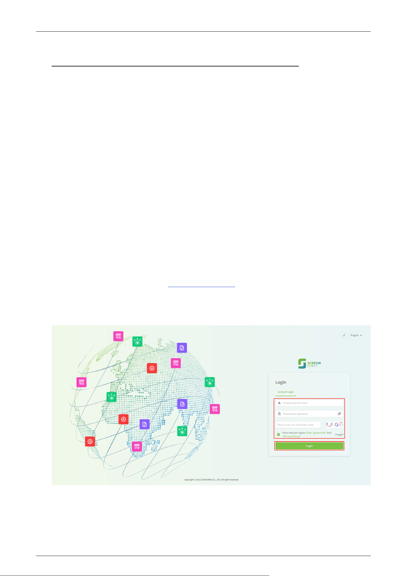
Please follow the instructions below to log in to the Screen Direct Website:
If the user has an account, follow these steps:
1. Access the Screen Direct Web at cmsl2.zkdigimax.com.
2. Log in using your user credentials: email, password and enter the verification code.
3. Then click “I have read and agree user agreement and privacy policy” and click Login.
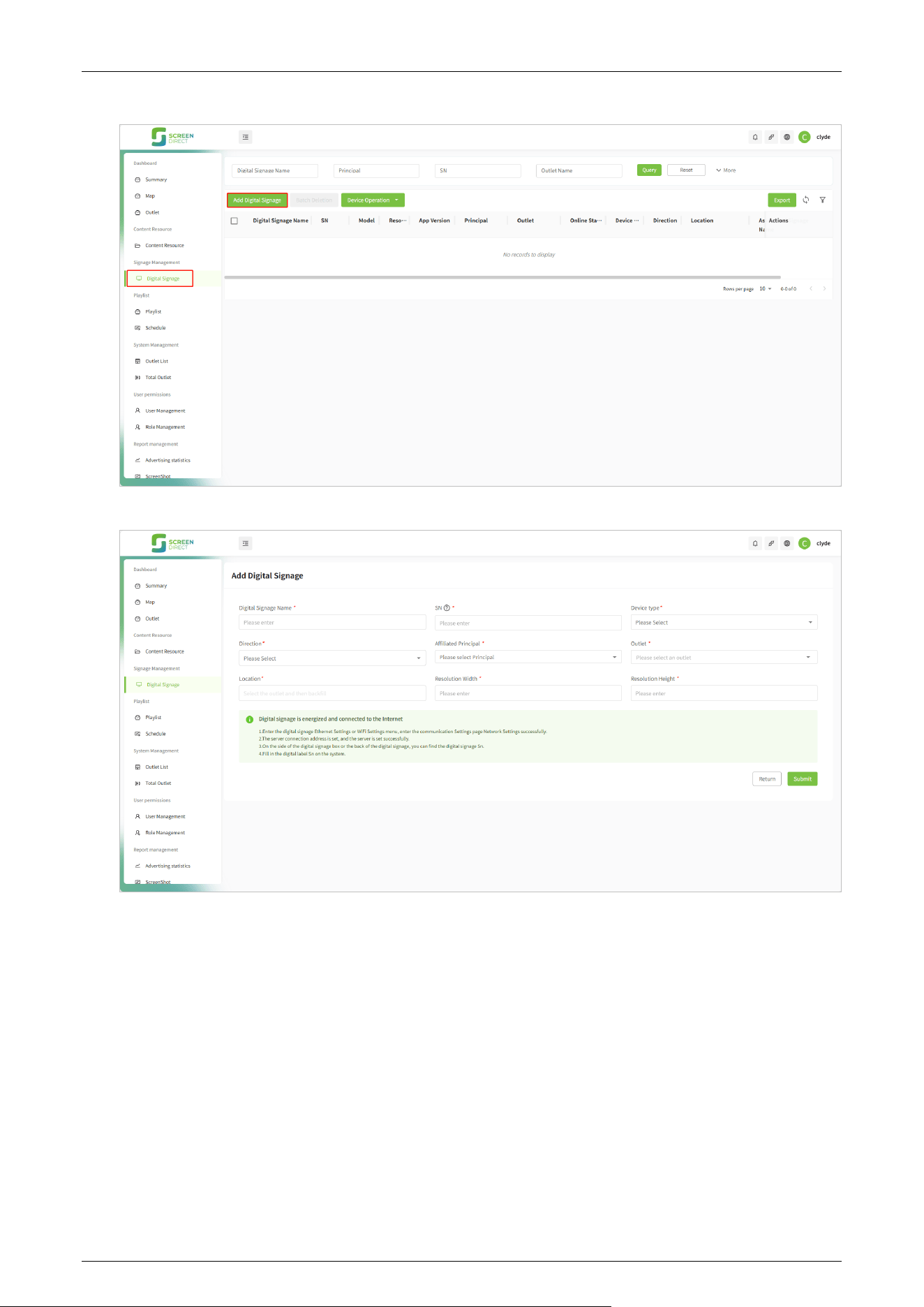
4. To add a device, click [Signage Management] > [Digital Signage] > [Add Digital Signage]. In
the pop-up Add New Digital Signage interface, enter the serial number displayed on the device
to bind it.
Saturn-S4000 Series User Manual
Page | 47 Copyright©2026 ZKTECO CO., LTD.All Rights Reserved.
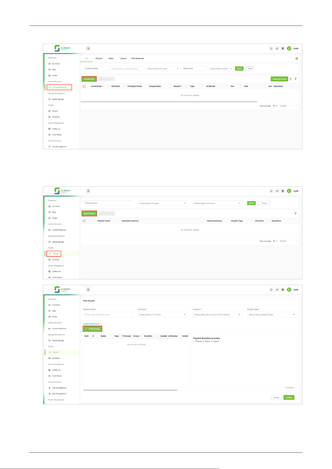
5. Upload content assets. Click [Content Resource] - [Content Resource] - [Upload ADs].
Saturn-S4000 Series User Manual
Page | 48 Copyright©2026 ZKTECO CO., LTD.All Rights Reserved.
6. Create a playlist. Click [Playlist] - [Playlist] - [New Playlist] to add a new playlist. Then select the
recently uploaded media, and finally save.
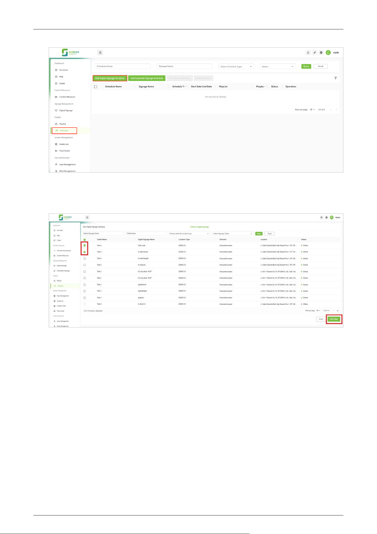
7. Create a schedule. Click [Playlist] - [Schedule] - [New Digital Signage Schedule]. Then to select
a digital signage.
Saturn-S4000 Series User Manual
Page | 49 Copyright©2026 ZKTECO CO., LTD.All Rights Reserved.
8. After that select one or more digital signage that we want to set the schedule and click [Next
Step], as shown below.
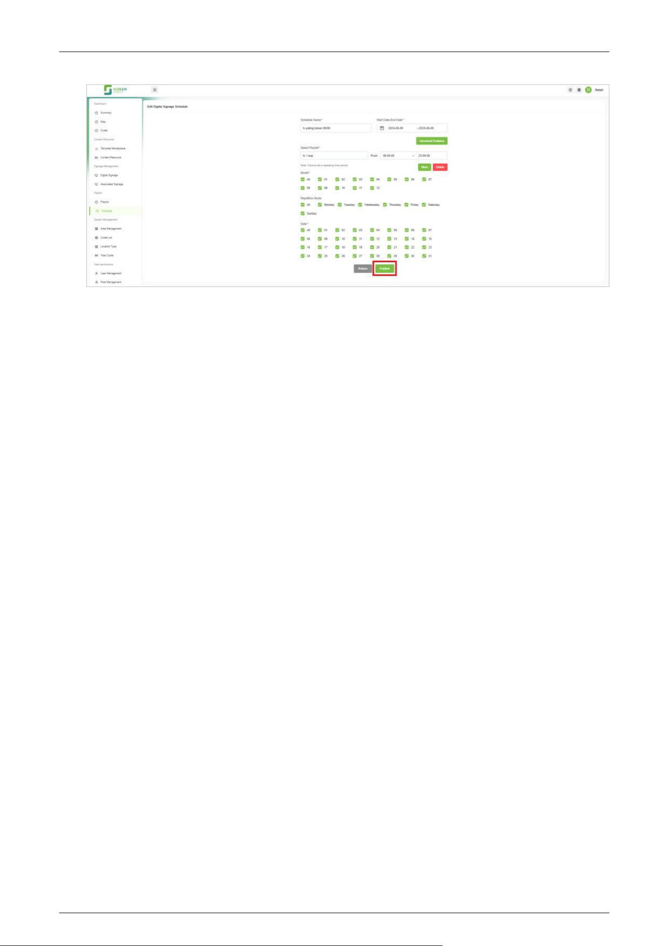
9. Next, enter the basic information for the digital signage schedule. This includes setting the
schedule name, defining the playback time, selecting the playlist, set the playback time for each
item, and configuring the month, repetition mode, and date of the schedule. Once you have
completed these settings, click [Publish] to finalize.
Saturn-S4000 Series User Manual
Page | 50 Copyright©2026 ZKTECO CO., LTD.All Rights Reserved.

Saturn-S4000 Series User Manual
Page | 51 Copyright©2026 ZKTECO CO., LTD.All Rights Reserved.
9 Maintenance
Cleaning and Maintenance 9.1
1. Regular Cleaning: Regularly wipe the surface of the cold plate spray-painted area with a soft
cloth or soft brush to remove dust and dirt. Avoid using hard objects or rough tools to prevent
scratching the surface.
2. Special Situation Handling: If there are difficult-to-remove stains such as paint or glue on the
surface, use professional cleaning agents for cleaning. Avoid using highly corrosive chemicals to
prevent damage to the spray-painted coating.
Coating Inspection and Repair 9.2
1. Regular Inspection: Regularly check the integrity of the spray-painted coating, looking for
scratches, wear, or peeling. If coating damage is found, it should be repaired in a timely manner.
2. Coating Repair: For minor scratches or wear, use professional spray-painting repair tools and
materials for local repair. Ensure the coating is smooth and aesthetically pleasing after repair.
Mechanical Component Maintenance 9.3
1. Fastener Inspection: Regularly check all fastening bolts and connecting parts to ensure they are
not loose. If any looseness is found, tighten them promptly.
2. Lubrication Maintenance: Regularly lubricate the transmission and moving parts to maintain
good lubrication. Use suitable lubricating oil or grease to avoid damage to components due to
insufficient lubrication.
Electrical Component Maintenance 9.4
1. Cleaning and Inspection: Keep electrical components clean and regularly check that electrical
connections are secure. Avoid electrical failures due to dust accumulation or loose connections.
2. Safe Operation: When inspecting and maintaining electrical components, the power must be
disconnected to ensure operational safety.
Caution: By following the above methods, the service life of the equipment can be effectively
extended, and its appearance and performance can be maintained in good condition. It should be
noted that the maintenance and care must be carried out by personnel who have undergone
professional training, especially for the core mechanism and electrical control parts. The power
supply must be disconnected first to ensure safe operation.

Saturn-S4000 Series User Manual
Page | 52 Copyright©2026 ZKTECO CO., LTD.All Rights Reserved.
10 Troubleshooting
No. Failure Descriptions Analysis and Solution
1
The mode indicator light does not
respond or the indication is
incorrect.
Check that the control panel mode indicator wiring
is correct or that the contact is poor.
2
After swiping the card, there is only a
speed gate unlocked.
Check the mode setting of the main and sub
devices and the 2-core connection lines. See the
wiring diagram for the specific connection circuit.
3
The barrier doesn’t close when the
opening delay time is expired.
Check to see if the opening delay time is too long
or whether the sensor is covered.
4
When the gate is self-tested, the
swing arm is not in the normal
closing position.
During self-test, if obstacles are detected, remove
them and restart the self-test after powering on.
Saturn-S4000 Series User Manual
Page | 53 Copyright©2026 ZKTECO CO., LTD.All Rights Reserved.
11 Packing List
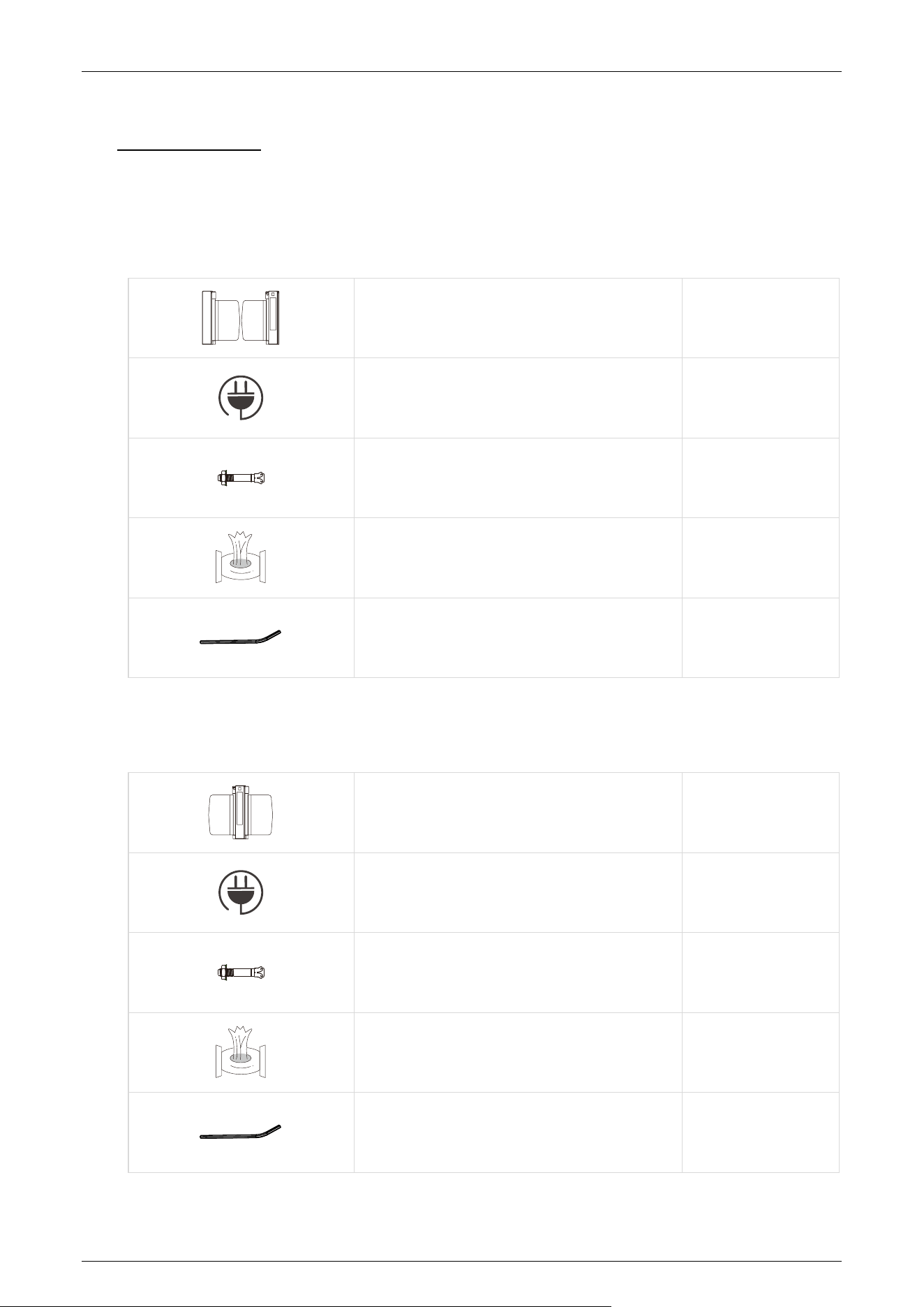
The package consists of the following items:
Saturn-S4000:
Saturn-S4000 (Primary and Secondary) 2
Power Cable 1
Expansion Screw M12*100 8
Stainless Steel Maintenance Wipes 1
Hex Wrench 1
Saturn-S4200:
Saturn-S4200 1
Power Cable 1
Expansion Screw M12*100 4
Stainless Steel Maintenance Wipes 1
Hex Wrench 1

Saturn-S4000 Series User Manual
Page | 54 Copyright©2026 ZKTECO CO., LTD.All Rights Reserved.
Revision History
Revision Date Author Reviewer Description
V1.0 20/01/2026 Julia Huang Original Document
V1.0 24/03/2026 Stella Xia Modify the parameters

Page | 55 Copyright©2026 ZKTECO CO., LTD.All Rights Reserved.
ZKTeco Industrial Park, No. 32, Industrial Road,
Tangxia Town, Dongguan, China.
Phone : +86 769 - 82109991
Fax : +86 755 - 89602394
www.zkteco.com
Copyright © 2026 ZKTECO CO., LTD. All Rights Reserved.