User Manual
X10
Version: 1.0
Due to regular upgrades of systems and products, ZKTeco could not guarantee exact consistency between the
actual product and the written information in this manual.
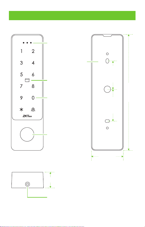
1.Overview
1
Status Indicator
Touch Button
Card Reading Area
Fingerprint Sensor
Mounting Hole
159.0mm
44.0mm
22.0mm
Backplate
38.8mm43.5mm
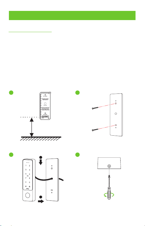
2.Device Installation
2
Install on the wall
①
②
③
④
Attach the mounting template sticker to the wall, and drill
holes according to the mounting paper.
Fix the backplate on the wall with the wall mounting screws.
After passing the wires through the wiring hole and connecting
them to the device, and then snap the device onto the backplate
and push it down into place.
Fasten the device to the backplate with a security screw.
1
2
4
3
1.5m
Baseline
2
1
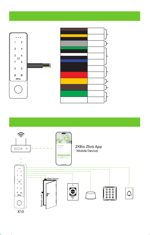
3.Terminal Block
Power In
Lock
Door Bell
Exit Button
Alarm
Bell A
Bell B
Alarm
NC
COM
NO
GND
12V
OPEN
D_IN
D0
D1
Brown & Black
Yellow & Black
Grey
Green & Black
White & Black
Blue & Black
Black
Red
Yellow
Brown
Green
White
Wiegand In
Door Sensor
4.Configuration
Wireless Network
Exit Button
Alarm Card Reader Door Bell
Output
Wiegand
3
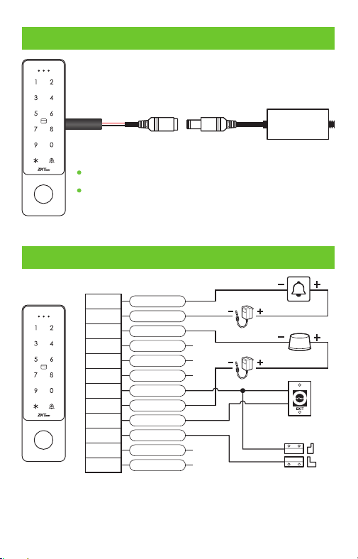
5.Power Connection
AC Adapter
DC12V, 1.5A
Recommended AC adapter , .: 12V 1 5A
To share power with other devices, use an AC
adapter with higher current ratings.
4
6.Exit Button, Door Sensor & Alarm Connection
Brown & Black
Yellow & Black
Grey
Green & Black
White & Black
Blue & Black
Black
Red
Yellow
Brown
Green
White
Bell A
Bell B
Alarm
NC
COM
NO
GND
12V
OPEN
D_IN
D0
D1
Door Sensor
Exit button
Alarm
Door Bell
+12V DC
+12V DC
Note: Supports 24V DC, 1A max for 2-wire doorbells. Do not
connect to AC power or exceed the specified load to prevent
relay damage.
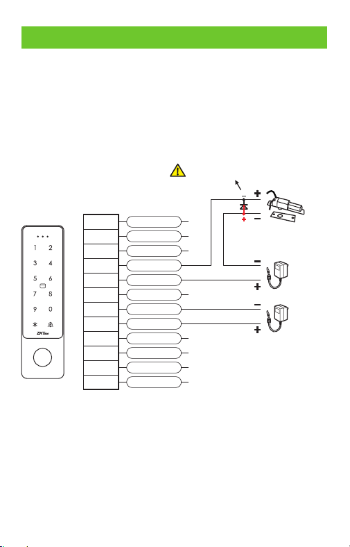
The system supports both Normally Opened Lock and Normally
Closed Lock. The NO LOCK (normally opened at power on) is
connected with 'NO' and 'COM' terminals, and the NC LOCK
(normally closed at power on) is connected with 'NC' and 'COM'
terminals. Take NC Lock as an example below:
7.Lock Relay Connection
Normally Closed Lock
5
Note: Protection diode model: 1N4004, standard configuration.
Brown & Black
Yellow & Black
Grey
Green & Black
White & Black
Blue & Black
Black
Red
Yellow
Brown
Green
White
Bell A
Bell B
Alarm
NC
COM
NO
GND
12V
OPEN
D_IN
D0
D1
+12V DC
+12V DC
1N4004
Do not reverse the polarity.
*Restore factory settings: Power off the device. Then, connect the
yellow wire (OPEN) to the black wire (GND). After 5 seconds, the
device will emit a single beep. Disconnect the wires. The device will
reset to factory defaults, and the administrator password will revert
to the default password (123456).
Note: User data and the binding relationship between the X10 and
the app will remain unchanged after the reset.
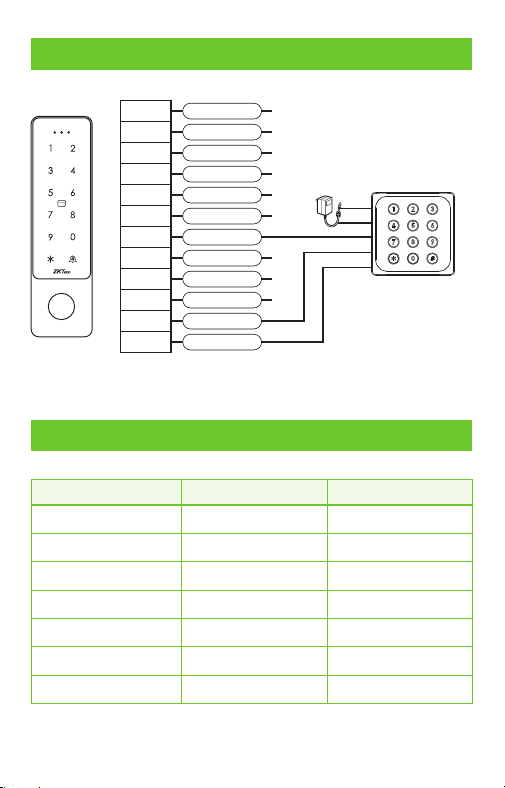
8.Wiegand Connection
Brown & Black
Yellow & Black
Grey
Green & Black
White & Black
Blue & Black
Black
Red
Yellow
Brown
Green
White
Bell A
Bell B
Alarm
NC
COM
NO
GND
12V
OPEN
D_IN
D0
D1
+12V DC
6
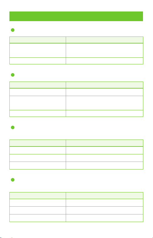
9.Indicator and Buzzer Instructions
Operating Status
Indicator Light
Standby Mode
Valid Key Press
Enter Programming
Enter Settings
Operation Error
Unlock
Alarm
Buzzer
Red steady
/
Red slow flash
Orange steady
/
Green
Red fast flash
/
Beep —
Beep —
Beep
Beep-beep-beep
Beep —
Alarm sound
Card Reader
10.Key Operation Instructions
Enter administrator programming mode
Programming Step Key Combination
Enter programming mode
Exit programming mode
[Administrator Password] #
*
(The factory default is 123456)
*
Modify administrator password
Programming Step Key Combination
Enter programming mode [Administrator Password] #
*
Initiate password change
0 [New Password #] [Repeat New
Password #] (Password is 6-digit)
Exit programming mode
*
Unlock time setting
Programming Step Key Combination
Enter programming mode [Administrator Password] #
*
Set unlock time
3 (1 - 100) #
Exit programming mode
*
Unlock time setting range: 1 to 100 seconds, factory default 5 seconds.
Alarm time setting
Programming Step Key Combination
Enter programming mode [Administrator Password] #
*
Enter the alarm duration
5 (0 - 3 minutes) #
Exit programming mode
*
The factory default setting is 1 minute.
7

Safe mode settings
Programming Step Key Combination
Enter programming mode [Administrator Password] #
*
Disable Safe Mode
Enable Lockout Mode
Enable Alarm Mode
Disable Door Sensor Alarm
Enable Door Sensor Alarm
6 (0) # (Factory default)
6 (1) #
6 (2) #
6 (3) # (Default)
6 (4) #
Exit programming mode
*
Lockout Mode: If an invalid card or password is entered 10 times within
10 minutes, the machine will lock out for 10 minutes.
Alarm Mode: If an invalid card or password is entered 10 times within
10 minutes, the buzzer will sound an alarm.
8
Indicator light and sound settings
Programming Step Key Combination
Enter programming mode [Administrator Password] #
*
Buzzer mute
Turn buzzer volume on
Turn off red light
Turn on red light
Turn off keypad light
Turn on keypad light
Keypad light turns off after
20 seconds
7 (0) #
7 (1) # (Default)
7 (2) #
7 (3) # (Default)
7 (4) #
7 (5) #
7 (6) # (Default)
Exit programming mode
*
The brown wire (D_IN) is the green light control line, and the yellow
wire (OPEN) is the buzzer control line, which is active at a low level.
Alarm disarm method
administrator password followed by #, or use a valid user card or password
followed by # to disarm the alarm.
Garbled code input instructions
Garbled code input only applies to 6-digit password entry for door
opening. The total garbled code length must not exceed 10 digits.
For example, if you set your password to 666666, entering the garbled
code 1236666669 on the device will still pass verification successfully.
9
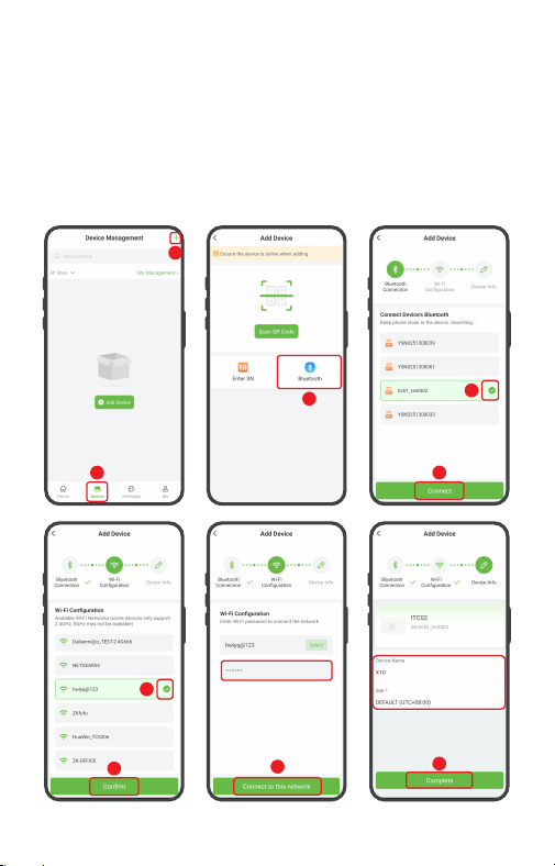
11.Connect to ZKBio Zlink App
1. First, you must enter configuration mode on the device. Press
* [Admin Password] # > 9 [Admin Password] #. The default
admin password is 123456 and can be changed. For example:
Press *123456#9123456# . The device beeps once.
2. Enable Bluetooth on your phone, then open the ZKBio Zlink
App. Click [Device] > icon > [Bluetooth] to connect the +
device via Bluetooth. The device will beep three times upon
successful connection. (See diagram step 1, 2, 3)
3. In the list of detected devices, identify and add the device
using its serial number. Click [Connect] to connect the device
and configure Wi-Fi. (See diagram step 4,5)
4. Then from the list of searched Wi-Fi networks, select the
one you want to connect to and click [Confirm]. After entering
the password, click [Connect to this network]. (See diagram
step 6,7,8)
Add Device
10
1
2
3
4
5
7
6
8
9
5. Enter the device name and specify the device to a site. Click
[Complete]. A “Added successfully” prompt will appear
simultaneously. (See diagram step 9)
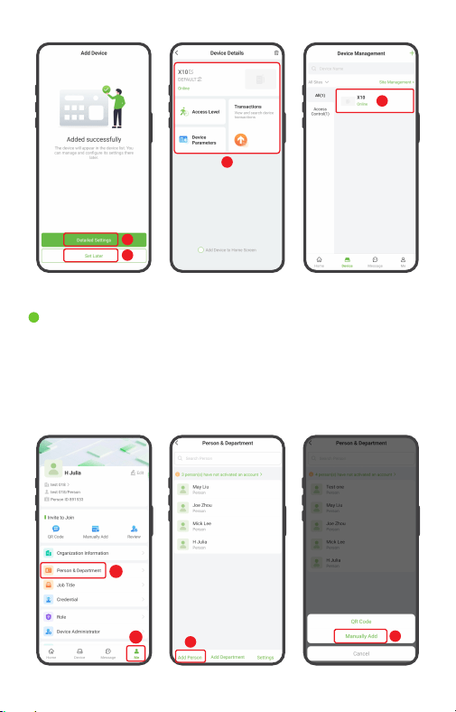
6. Once successfully added, the device is displayed in the list
of the device interface. Click [Detailed Settings]/[Set Later] to
enter the corresponding interface. (See diagram step 10,11)
11
Add Person & Department
11
10
10
11
In the bottom menu of the app, click [Me] > [Person & Depart-
ment] > [Add Person]. You may choose to add either QR Code
or Manually Add. Then, in the Add Person screen, enter the person's
details. (See diagram step 1,2,3,4)
1
2
3
4
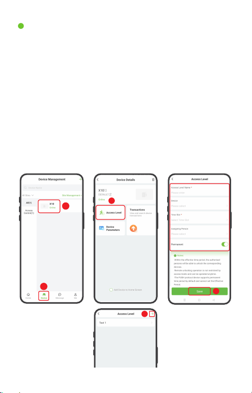
Set Access Levels
4
12
1
2
3
1. Click [Device] to enter the Device Management interface.
And select the device from the list. (See diagram step 1,2)
2. Then click [Access Level] to enter the Access Level interface.
Click the icon in the upper-right corner to add an access +
level. (See diagram step 3,4)
3. Set the name, select the device, time slot, persons, and click
[Save] to synchronize the access level to the device. (See
diagram step 5)
Note: There is a default timeslot named 24-hour access
in the system.
5
13
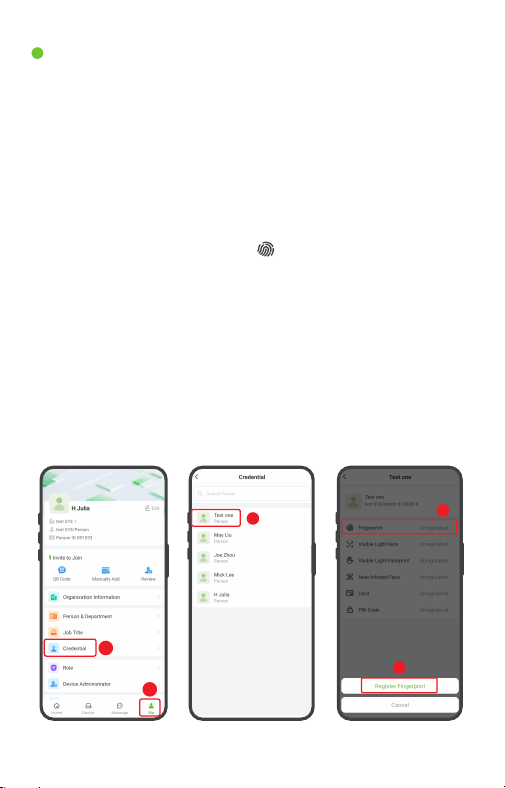
Once you have added persons to the device, you can register
verification modes to them.
Register Fingerprint:
1. Click [Me] > [Credential] to enter the Credential screen,
select the person who needs to register verification mode.
(See diagram step 1,2,3)
2. On the details screen, click the icon > [Register Fingerprint],
then select the device and fingerprint you want to register.
When you select the device to be registered, it will beep.
After hearing the beep, tap the scanner three times. (See
diagram step 4,5,6,7,8)
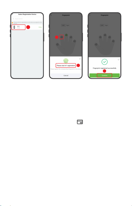
3. Once complete, tap [Confirm]. Registered fingerprints will
appear in green on the screen. And you can repeat the
above operation to register other fingers. (See diagram
step 9)
Register Verification Mode
3
1
2
4
5
9
7
8
6
14
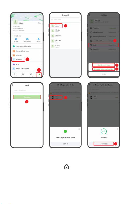
Register Card:
1. Click [Me] > [Credential] to enter the Credential screen,
select the person who needs to register verification mode.
(See diagram step 1,2,3)
2. On the details screen, click the icon. You can select
Register on Device or Manually Enter Card Number. If you
want to register on device, then click [Register on Device].
(See diagram step 4,5,6,7,8)
3. When selecting a device for registration, the device will
illuminate a green light and emit a beep. Place the card in
the swipe area. The final beep indicates successful card
registration.
4. Click [Complete] to return.(See diagram step 9)
15
3
1
2
4
5
8
9
6
7
Register Password:
On the details screen, click the icon > [PIN Code] , enter the
password in the pop-up window, and then click [Complete].
The device will beep three times to indicate successful registra-
tion. For more detailed information, please refer to the relevant
software user manual.
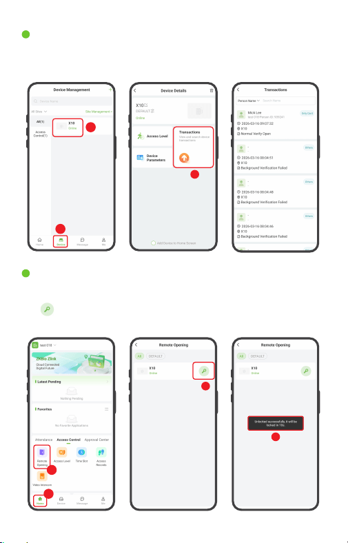
Remote Opening
Click [Home] > [Access Control] > [Remote Opening], then click
the icon to remotely unlock the door. After the door opens,
a success message will appear on the screen.
1
2
3
4
View Records
Employee access records can be viewed in the [Transactions]
section of the device details interface.
16
1
2
3

ZKTeco Industrial Park, No. 32, Industrial Road,
Tangxia Town, Dongguan, China.
Phone : +86 769 - 82109991
Fax : +86 755 - 89602394
www.zkteco.com
Copyright © 2026 ZKTECO CO., LTD. All Rights Reserved.