
IC7.9 INDOOR CYCLE OWNER’S MANUAL


3
INDOOR CYCLE OPERATION
4
2 ft
60 cm
2 ft
60 cm
2 ft 60 cm
2 ft 60 cm
FRONT
REAR
BIKE
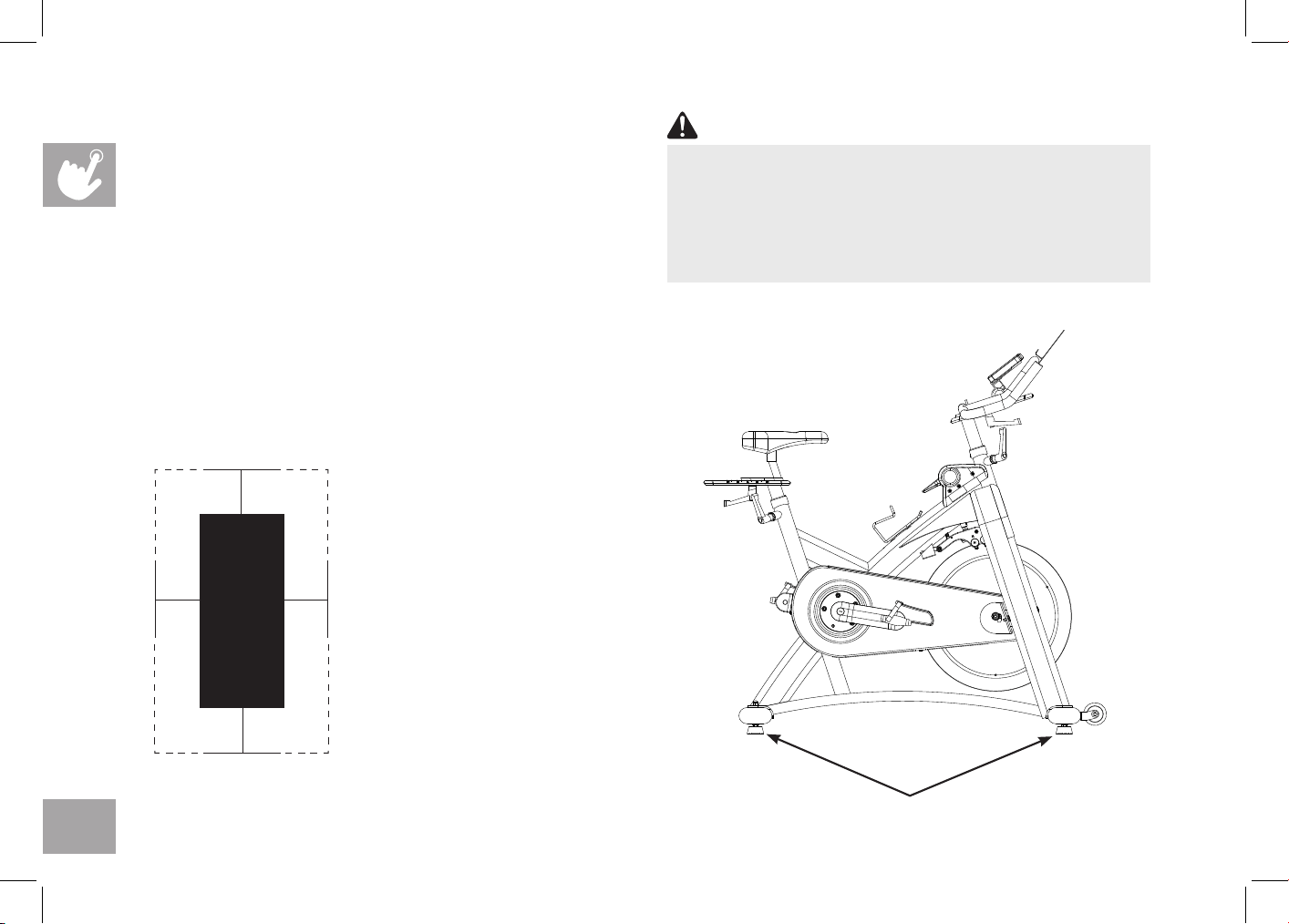
HOW TO MOVE THE INDOOR CYCLE
Due to the weight of the Indoor Cycle, it is recommended
that two persons move it. While one person lifts the back
of the indoor cycle, the second person firmly holds the
handlebar and tips the indoor cycle forward until it rolls on
the wheels. Carefully move the Indoor Cycle to the desired
location and then lower it.
If the Indoor Cycle rocks on the floor after being set
down, turn the leveling feet underneath the front or rear
stabilizer until the rocking motion is eliminated.
Leveling Feet
To reduce the risk of injury, use extreme caution
while moving the indoor cycle. Do not attempt to
move it over uneven surfaces and make sure there’s
a safety space of 20 inch (minimum) to the nearest
equipment is recommended.
WARNING
LOCATION OF THE
INDOOR CYCLE
Place the Indoor Cycle on a
level surface. There should be
2 feet (60 cm) of each side
surround the Indoor Cycle. Do
not place the cycle in any area
that will block any vent or air
openings. The Indoor Cycle
should not be located in a
garage, covered patio, near
water or outdoors.
5
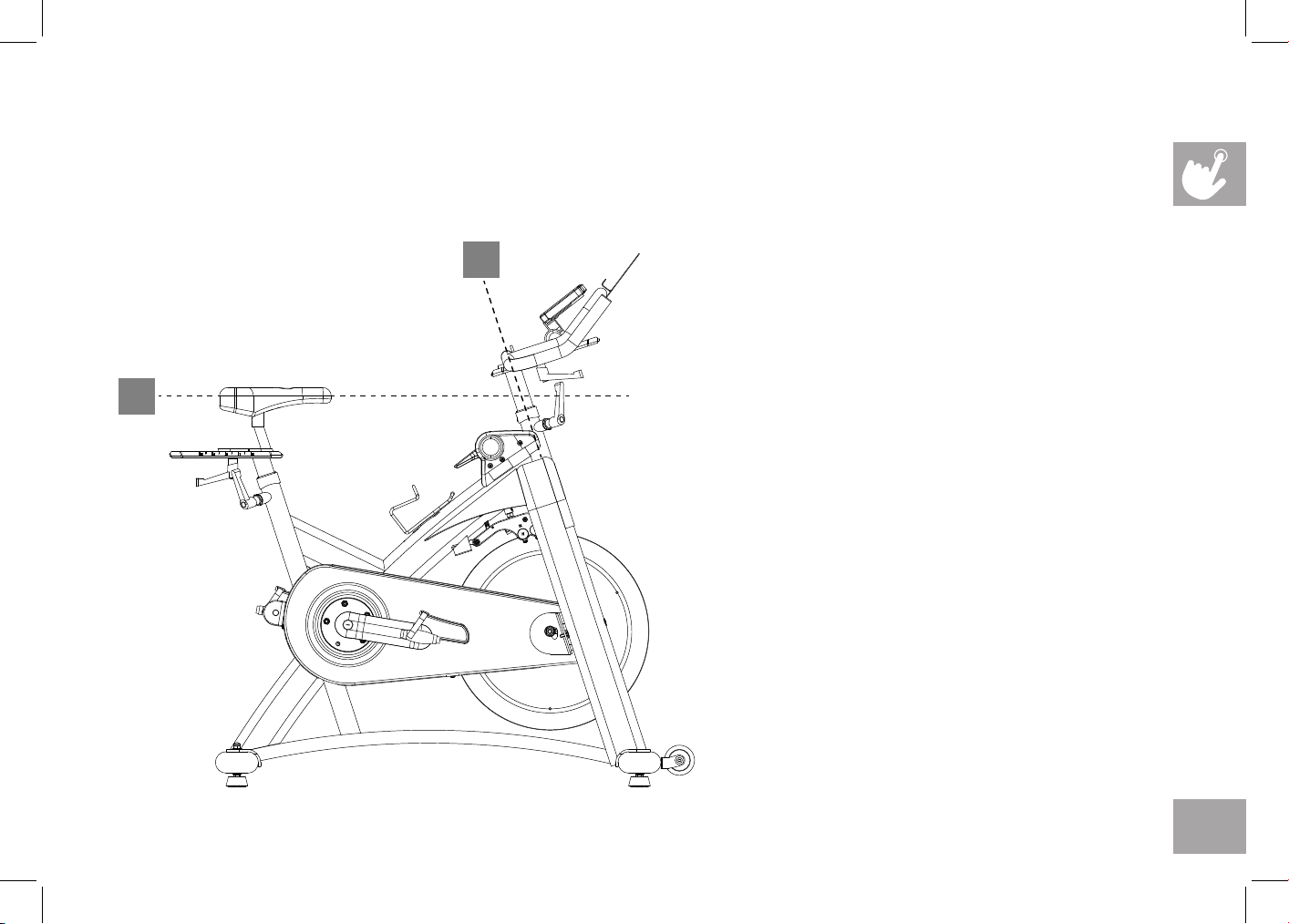
HOW TO ADJUST THE INDOOR CYCLE
The Indoor Cycle can be adjusted for maximum comfort and exercise effectiveness. The instructions below describe one
approach to adjusting the Indoor Cycle to ensure optimal user comfort and ideal body positioning; you may choose to adjust
the Indoor Cycle differently.
SADDLE ADJUSTMENT
Proper saddle height helps ensure maximum
exercise efficiency and comfort, while
reducing the risk of injury. Adjust the saddle
height to make sure it’s in proper position,
one that keeps a slightly bend in your knee
while your legs are in the extended position.
HANDLEBAR ADJUSTMENT
Proper position for the handlebar is based
primarily on comfort. Typically, the handlebar
should be positioned slightly higher than
the saddle for beginning cyclists. Advanced
cyclists could try different heights to get the
arrangement most suitable for you.
A
B
6
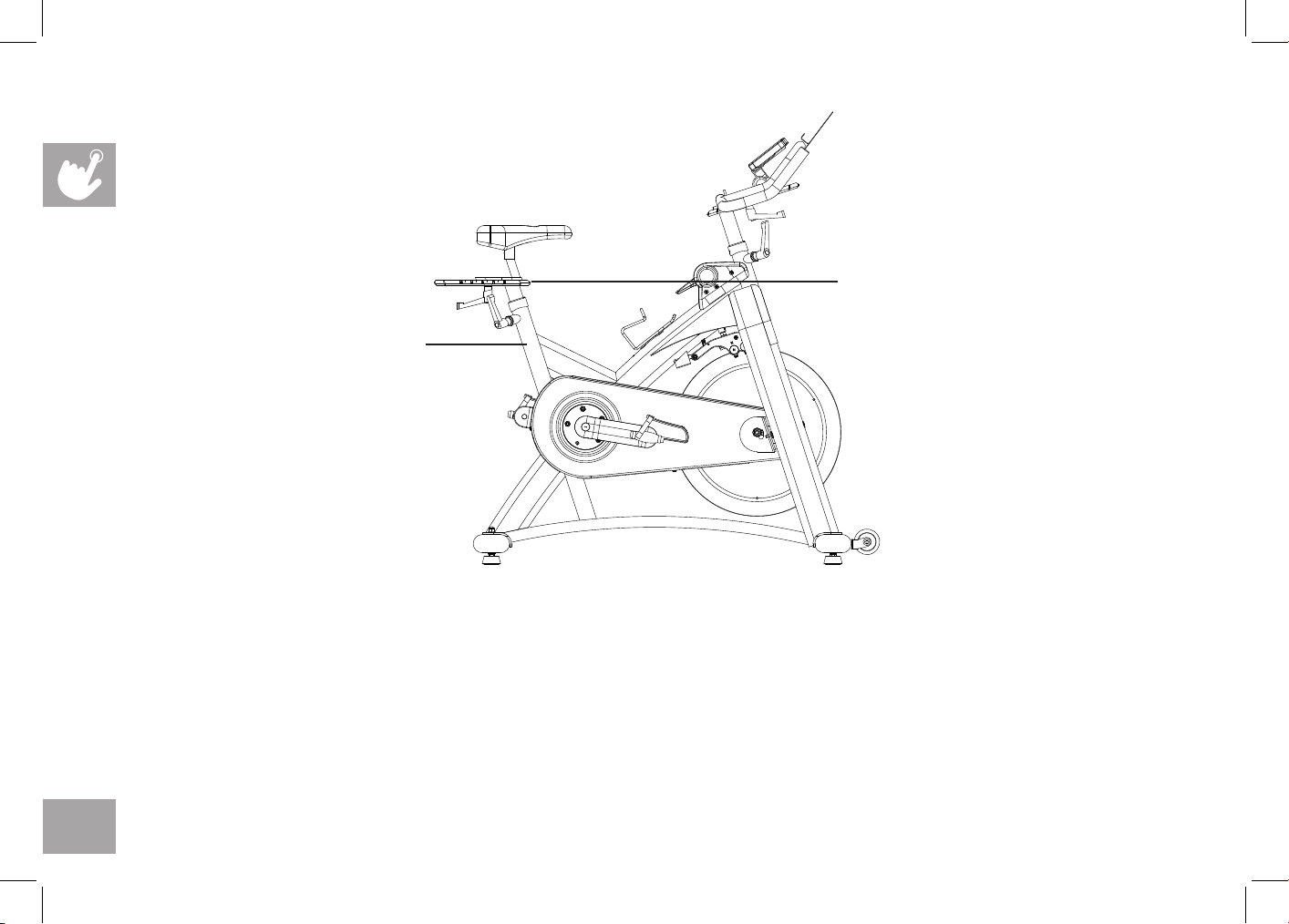
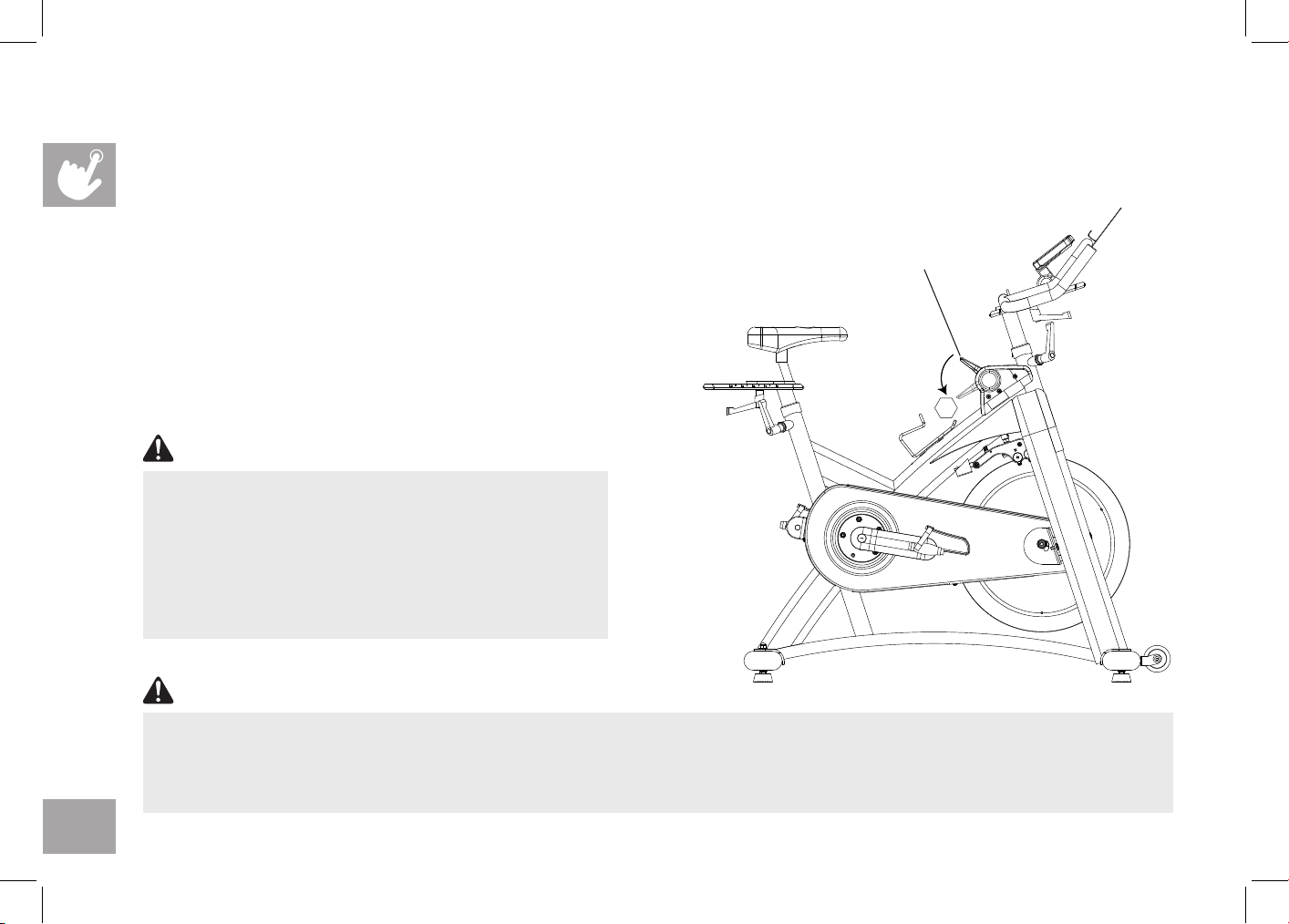
TO ADJUST THE SADDLE HEIGHT:
Rotate the adjustment lever counterclockwise and adjust the saddle to a comfortable pedaling position. Rotate the lever
clockwise to lock saddle position.
TO ADJUST THE SADDLE HORIZONTAL POSITION:
Rotate the adjustment lever counterclockwise to slide the saddle forward or backward as desired. Rotate the lever clockwise
to lock saddle position. Test the saddle slide for proper operation.
Do not adjust the
saddle position
beyond the stop
marks on the
saddle slider
Do not adjust
saddle height
beyond the
stop mark on
the stem
7
TO ADJUST THE HANDLEBAR HEIGHT:
Rotate the adjustment lever counterclockwise to adjust the handlebar height. Raise or lower the handlebar to the desired
height. Rotate the lever clockwise to lock handlebar position.
TO ADJUST THE PEDAL STRAPS:
Place each foot ankle on the pedal and in the toe clip that the foot ankle is centered over the pedal spindle (center of the
pedal). Rotate one foot to arms reach and pull up on the toe clip strap. Repeat for the other foot. Keep your knees over your
feet as you pedal. To remove your foot from the toe clip, loosen the strap and pull out.
Do not adjust the
handlebar height
beyond the stop
mark on the stem.
The pedal straps should
be adjusted to hold the
foot snugly in the pedal.
8
STOP
TENSION CONTROL AND EMERGENCY BRAKE
The preferred level of difficulty in pedaling (resistance) can be regulated in increments by use of the tension control
lever. To increase the resistance, push the tension control lever downward towards the ground. To decrease the resistance,
pull the handle upwards.
IMPORTANT:
• To stop the flywheel while pedaling, push down hard on the
tension control lever until the brake rubs on the flywheel.
• The flywheel should quickly come to a complete stop.
• Make sure your shoes are fixed into the toe clip.
• Apply full resistance load when the bike is not in use to
prevent injuries due to moving drive gear components.
Tension control lever
Emergency brake
The Indoor Cycle does not have a free moving flywheel; the
pedals will continue to move together with the flywheel
until the flywheel stops. Reducing speed in a controlled
manner is required. To stop the flywheel immediately,
push down hard the tension control lever. Always pedal
in a controlled manner and adjust your desired cadence
according to your own abilities. Push the tension control
lever down = emergency stop.
WARNING
The Indoor Cycle uses a fixed flywheel that builds momentum and will keep the pedals turning even after the user stops pedaling or if
the user’s feet slip off. DO NOT ATTEMPT TO REMOVE YOUR FEET FROM THE PEDALS OR DISMOUNT THE MACHINE UNTIL
BOTH THE PEDALS AND THE FLYWHEEL HAVE COMPLETELY STOPPED. Failure to follow these instructions may lead to loss of
control and the potential for serious injury.
WARNING
9
ASSEMBLY
There are several areas during the assembly process that special attention must be paid. It is very important to follow the
assembly instructions correctly and to make sure all parts are firmly tightened. If the assembly instructions are not followed
correctly, the indoor cycle could have parts that are not tightened and will seem loose and may cause irritating noises. To
prevent damage to the indoor cycle, the assembly instructions must be reviewed and corrective actions should be taken.
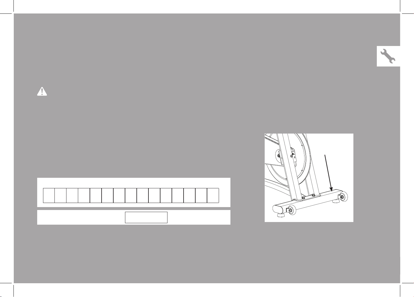
Before proceeding, find your indoor cycle’s serial number located on
the front stabilizer of the cycle and enter it in the space provided below.
ENTER YOUR SERIAL NUMBER IN THE BOX BELOW:
» Refer to the SERIAL NUMBER and MODEL NAME when calling for service.
» Be sure to enter both the SERIAL NUMBER and MODEL NAME on your warranty card.
SERIAL NUMBER:
MODEL NAME:
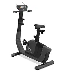
HORIZON INDOOR CYCLE
WARNING
36

10
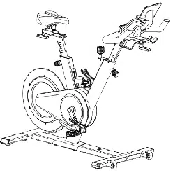
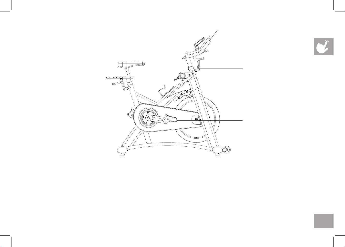
Saddle
Resistance Control Handle & Emergency Brake
Quick Release
Tablet Holder
Console
Heavy Flywheel
Transportation Wheel
Durable Crank
Seat Post
Seat Slider
MODEL INFORMATION

11
MAIN PARTS INCLUDED:
Main Frame
Front Stabilizer
Rear Stabilizer
Handlebar Set
Handlebar Mast Set
Console
Pedal Set
Seat Post Set
PARTS PACKING
INCLUDED:
1 Parts box
1 Owner’s Manual
PRE ASSEMBLY
If you have questions or if there
are any missing parts, contact your
local dealer. Contact information
may be located on the back panel
of this manual or on warranty card.
UNPACKING
Due to the weight of the indoor cycle, it is recommended that two persons
perform the assembly. Set the indoor cycle in a cleared area and remove all
packing materials; do not dispose of the packing materials until assembly is
completed.
NOTE: During each assembly step, ensure that ALL nuts and bolts are in place
and partially threaded in before completely tightening any ONE bolt.
NOTE: A light application of grease may aid in the installation of hardware. Any
grease, such as lithium bike grease is recommended.
NEED HELP?
12
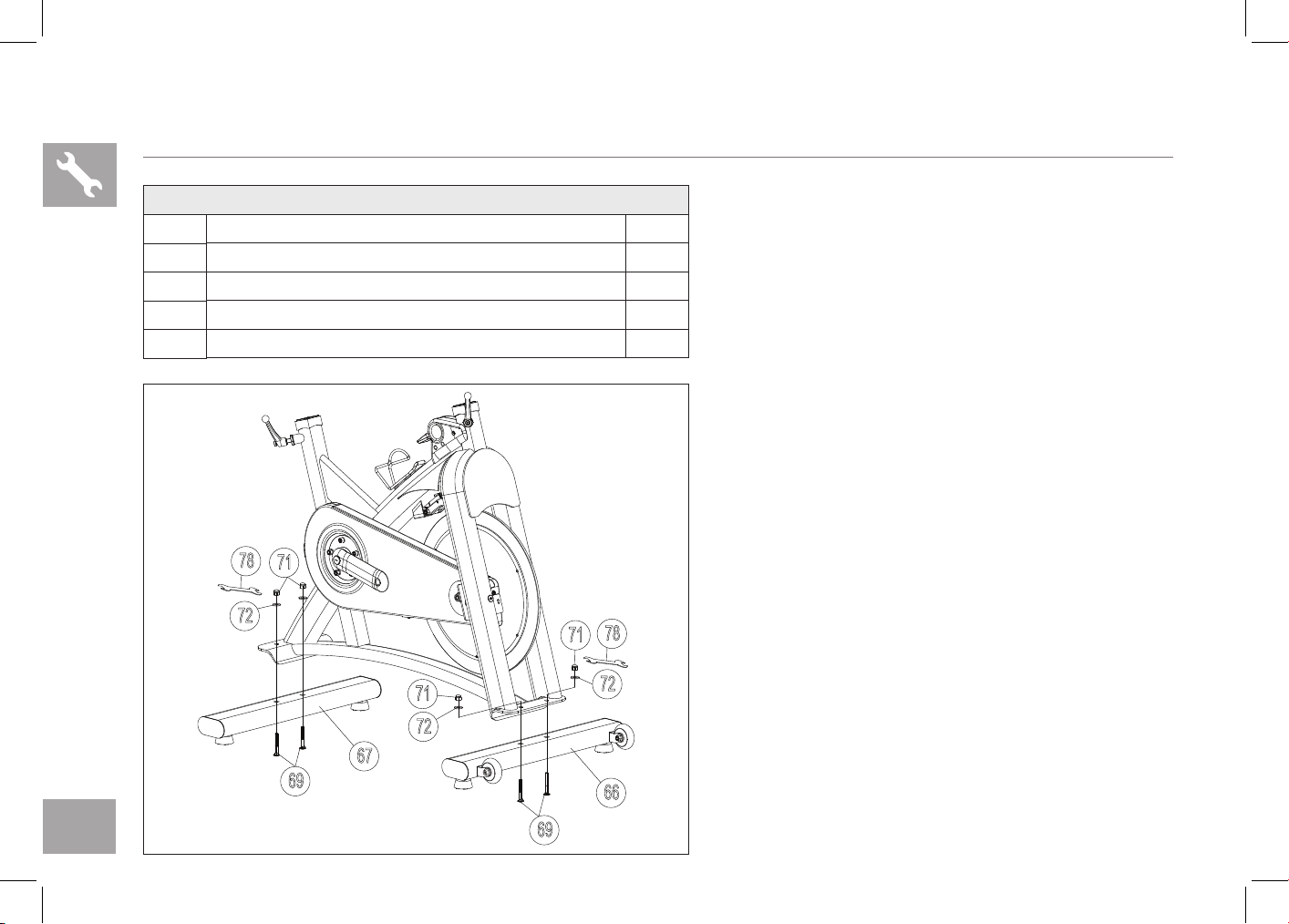
IC7.9 ASSEMBLY STEP 1
A Attach the FRONT STABILIZER (66) and REAR
STABILIZER (67) to the frame using 4 BOLTS
(69) and 4 WASHERS (72) and 4 NUTS (71), and
secure firmly by WRENCH (78).
HARDWARE FOR STEP 1 :
NO. DESCRIPTION QTY
69
BO LT 4
71
NUT 4
72
WASHER 4
78
WRENCH 1
71
72
69
78
69
66
71
72
67
71
72
78
13
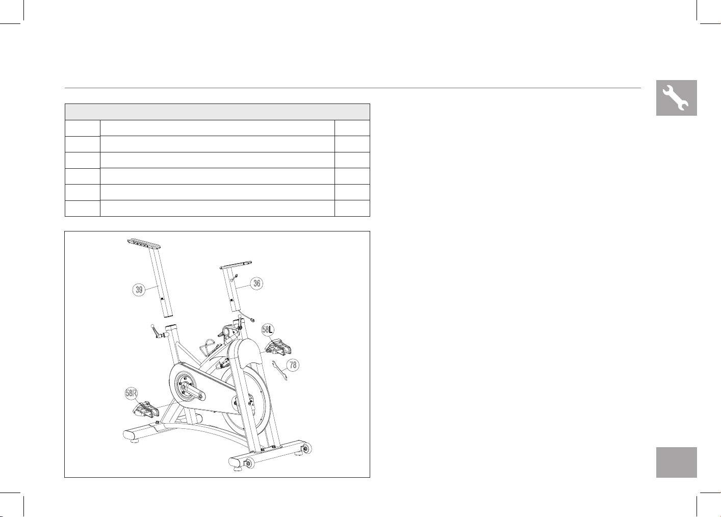
IC7.9 ASSEMBLY STEP 2
A Thread the LEFT PEDAL (58L) that has “L” on the
spindle to the left side arm of the cycle using the
WRENCH (78). Please note that the “L” pedal
is left-hand threaded which needs to be turned
counter clockwise to tighten.
B Thread the RIGHT PEDAL (58R) that has “R” on
the spindle to the right side arm of the cycle using
the WRENCH (78). Please note that the “R” pedal
is right-hand threaded which needs to be turned
clockwise to tighten.
C Install the HANDLEBAR MAST(36) into the frame
receptor and secure with the quick release.
D Install the SEAT POST(39) into the frame receptor
and secure with the quick release.
36
58R
58L
78
39
HARDWARE FOR STEP 2 :
NO. DESCRIPTION QTY
36
HANDLEBAR MAST 1
39
SE AT POST 1
58L
LEFT PEDAL 1
58R
RIGHT PEDAL 1
78
WRENCH 1
14
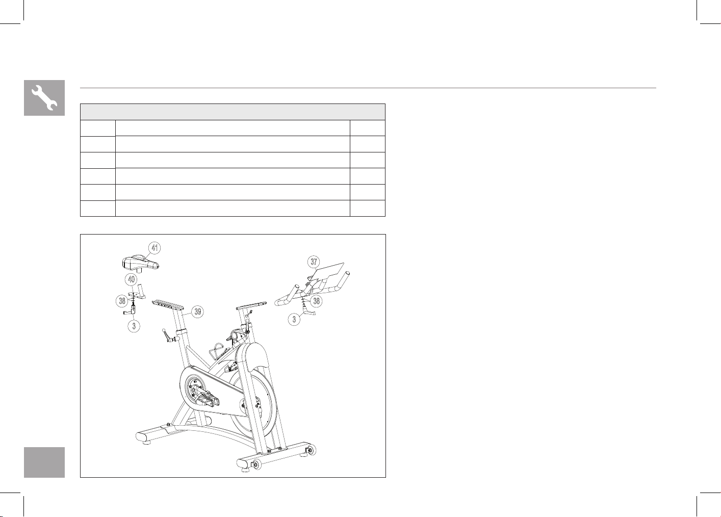
IC7.9 ASSEMBLY STEP 3
37
3
38
40
38
39
3
41
HARDWARE FOR STEP 2 :
NO. DESCRIPTION QTY
3
QUICK RELEASE 2
37
HANDLEBAR 1
38
WASHERS 4
40
SE AT SLIDER 1
41
SADDLE 1
A Install the HANDLEBAR (37) into the handlebar
mast receptor using 2 WASHERS (38) and secure
with the QUICK RELEASE(3).
B Install the SADDLE (41) into the SEAT SLIDER
(40) receptor and secure with the wrench.
C Attach the SEAT SLIDER (40) to the SEAT POST
(39) using 2 WASHERS (38) and secure with the
QUICK RELEASE(3).
15
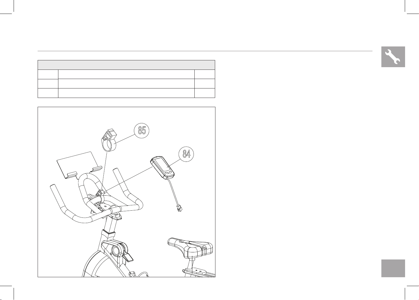
A Fix CONSOLE (84) with MOUNTING CLAMP (85)
from back.
HARDWARE FOR STEP 4 :
NO. DESCRIPTION QTY
84
CONSOLE 1
85
MOUNTING CLAMP 1
IC7.9 ASSEMBLY STEP 4
84
85
16
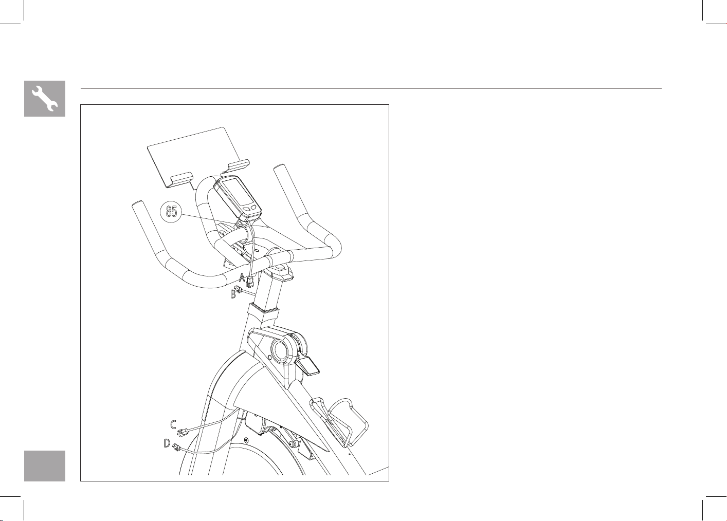
A Carefully attach the UPPER CONSOLE CABLE
(A) to the LOWER CONSOLE CABLE (B) pre-
assembled to the handlebar.
B Carefully attach the MAST CABLE (C) to the
FRAME CABLE (D) pre-assembled in the frame.
C Adjust console to preferred viewing angle.
NOTE: Check to see there is no loose cable that could
make contact with the flywheel once the cable harness
is assembled. Tuck away any loose cable.
D Congratulations, you have successfully assembled
the Indoor Cycle.
IC7.9 ASSEMBLY STEP 5
A
B
C
D
85

17
CONSOLE OPERATION

18
IC7.9 CONSOLE DISPLAY
MONITOR DISPLAY:
In the exercise mode, the LCD windows will display RPM, KCAL and ODO.
You can press left Key to change the display among TIME/SPEED/CLOCK/DISTANCE
LEFT & RIGHT KEY:
a. Press any key to wake up the console from energy saver mode.
b. During the exercise mode, press left change display among TIME/SPEED/CLOCK/DISTANCE.
IC7.9 CONSOLE OPERATION
CLOCK SETTING
Press the left key until CLOCK is displayed, press the right key for 3 seconds to enter setting mode to adjust clock setting.
Change the value by pressing right key and confirm by pressing left key, the console will automatically save the value given
after 5 seconds.
PERSONAL WORKOUT SETTING
Press the left key until SPEED is displayed, press the right key for 3 seconds to adjust personal data setting. (user weight; gender
left female/right male; time etc.) To change to between standard and metric press the right button when lb or kg is flashing. This will
also change the mile and km setting. Note: when the batteries are replaced the console will default to standard units.
RPM measures the user’s foot RPM, also known as cadence.
Change the value by pressing right key and confirm by pressing left key, the console will automatically save the value given
after 5 seconds.
ENERGY SAVER
To minimize energy consumption, your machine will enter energy saver mode automatically when not in use and could be quickly
woke up with a touch of a button.
KCAL
rpm
40
60
80
100
120
140
160
Am
LEFT KEY RIGHT KEY
MONITOR

19
TROUBLESHOOTING
& MAINTENANCE

20
COMMON PRODUCT QUESTIONS
ARE THE SOUNDS MY Indoor Cycle MAKES NORMAL?
Our Indoor Cycles are some of the quietest available because they use belt drives and cantilever brake resistance. We use
the highest grade bearings and chains/belts to minimize noise. However, because the resistance system itself is so quiet, you
will occasionally hear other slight mechanical noises. Unlike older, louder technologies, there are no fans, friction belts, or
alternator noises to mask these sounds on our Indoor Cycles. These mechanical noises, which may or may not be intermittent,
are normal and are caused by the transfer of significant amounts of energy to a rapidly spinning flywheel. All bearings, chains/
belts and other rotating parts will generate some noise which will transmit through the casing and frame. It is also normal for
these sounds to change slightly during a workout and over time because of thermal expansion of the parts.
WHY IS THE Indoor Cycle I HAD DELIVERED LOUDER THAN THE ONE AT THE STORE ?
All fitness products seem quieter in a large store showroom because there is generally more background noise than in your
home. Also, there will be less reverberation on a carpeted concrete floor than on a wood overlay floor. Sometimes a heavy
rubber mat will help reduce reverberation through the floor. If a fitness product is placed close to a wall, there will be more
reflected noise.
HOW LONG WILL THE BELT LAST?
The computer modeling we have done indicated virtually thousands of maintenance free hours. You should not have to
replace the belt as long as you have the Indoor Cycle.
CAN I MOVE THE Indoor Cycle EASILY ONCE IT IS ASSEMBLED?
Your Indoor Cycle has a pair of transport wheels built into the front stabilizer tube. Please follow the moving the Indoor
Cycle section to transport your Indoor Cycle. It is important that you place your Indoor Cycle in a comfortable and inviting
room. Your Indoor Cycle is designed to use minimal floor space. Many people will place their Indoor Cycles facing the TV or
a picture window. If at all possible, avoid putting your Indoor Cycle in an unfinished basement. To make exercise a desirable
daily activity for you, the Indoor Cycle should be in a comfortable setting.

21
TROUBLE SHOOTING
PROBLEM: The Indoor Cycle makes a squeaking or chirping noise.
SOLUTION: Verify the following:
• The Indoor Cycle is on a level surface.
• Loosen all bolts attached during the assembly process, grease the threads, and tighten again.
In order for Customer Tech Support to service your Indoor Cycle they may need to ask detailed questions about the symptoms
that are occurring. Some troubleshooting questions that may be asked are:
• How long has this problem been occurring?
• Does this problem occur with every use? With every user?
• If you are hearing a noise, does it come from the front or the back? What kind of noise is it (thumping,
grinding, squeaking, chirping etc.)?
• Has the machine been lubricated and maintained per the maintenance schedule?
Answering these and other questions will give the technicians the ability to send proper replacement parts and the service
necessary to get you and your Indoor Cycle running again!
If this does not remedy the problem, you may
CONTACT CUSTOMER TECH SUPPORT AT THE NUMBER ON THE INFORMATION CARD.
The following information may be asked of you when you call. Please have these items readily available:
• Model Name
• Serial Number
• Proof of Purchase (receipt or credit card statement)
You may find more troubleshooting suggestions on the customer support section of our website. Contact customer
support using the contact information on the INFORMATION CARD.

22
MAINTENANCE
The safety level given by the design of the Indoor Cycle can only be maintained when the equipment is regularly examined
for damage and wear. Inoperable components should be replaced or the equipment should be put out of use until it is
repaired.
DAILY
• Wipe down the Indoor Cycle after each use to remove sweat and moisture. Use soap and water, or a diluted non-abrasive
domestic cleaner solution. Rinse to remove detergent residue and then dry off.
• Before each session, inspect for loose components such as pedals or cranks prior to commencing the next use. Tighten
up any loose parts.
WEEKLY
• Check for proper flywheel alignment. Torque flywheel nuts as necessary.
• Check to make sure the crank arms are tight to the bottom bracket.
• Inspect all parts, nuts, bolts, or screws for adjustments, replacements or maintenance.
MONTHLY
• Inspect the frame and main assembly components for rust or corrosion. Tilt the cycle or place in an upside down position
to locate areas where rust and corrosion may develop. Use a small, wire brush to remove rust build-up in small crevasses,
such as leveling feet, quick release levers and other bolt assemblies.
• Inspect all wear items for adjustments or possible part replacement. Give particular attention to the following:
A) Inspect brake pad for wear. Excessive wear or dryness indicates replacement is required.
B) Inspect seat pad for wear. Rips, tears or excessive movement indicates replacement is required.
C) Inspect pedals for play. Excessive movement of pedals indicates replacement is required.
• Inspect the belt for tensioning by rotating the crank to drive the flywheel forward. Do this motion in 1/4 turns to assess if
there is free play between the crank and the flywheel.
• Dryness or prolonged use may cause the height and reach adjustments for the seat and handlebar to become tight. If this
is the case, the sliding assembly should be removed from the frame and have a smear of light duty grease applied along
the sliding surface before assembly. Similarly, apply some light grease to the clamping assembly to ensure it does not seize
up. Clean off excessive grease before reassembly.

23
LIMITED HOME-USE WARRANTY

24
WEIGHT CAPACITY = 300 lbs (136 kilograms)
FRAME • LIFETIME
Manufacturer warrants the frame against defects in
workmanship and materials for the period specified above
from the date of purchase, so long as the device remains in
the possession of the original owner. (The frame is defined as
the welded metal base of the unit and does not include any
parts that can be removed.)
ELECTRONICS & PARTS • 1 YEAR
Manufacturer warrants the electronic components, finish
and all original parts for a period of one year from the date
of original purchase, so long as the device remains in the
possession of the original owner.
LABOR • 1 YEAR
Manufacturer shall cover the labor cost for the repair of the
device for a period of one year from the date of the original
purchase, so long as the device remains in the possession of
the original owner.
EXCLUSIONS AND LIMITATIONS
Who IS covered:
• The original owner and is not transferable.
What IS covered:
• Repair or replacement of a defective motor, electronic
component, or defective part and is the sole remedy of
the warranty.
What IS NOT covered:
• Normal wear and tear, improper assembly or
maintenance, or installation of parts or accessories not
originally intended or compatible with the equipment
as sold.
• Damage or failure due to accident, abuse, corrosion,
discoloration of paint or plastic, neglect, theft,
vandalism, fire, flood, wind, lightning, freezing, or
other natural disasters of any kind, power reduction,
fluctuation or failure from whatever cause, unusual
atmospheric conditions, collision, introduction of
foreign objects into the covered unit, or modifications
that are unauthorized or not recommended by the
Manufacturer.
• Incidental or consequential damages. The Manufacturer
is not responsible or liable for indirect, special or
consequential damages, economic loss, loss of
property, or profits, loss of enjoyment or use, or
other consequential damages of whatsoever nature
in connection with the purchase, use, repair or
maintenance of the equipment. The Manufacturer

25
SERVICE/RETURNS
• In-home service is available within 150 miles of the
nearest authorized Service Provider (Mileage beyond
150 miles from an authorized service center is the
responsibility of the consumer).
• All returns must be pre-authorized by the Manufacturer.
• Manufacturer’s obligation under this warranty is limited
to replacing or repairing, at the Manufacturer’s option,
the same or comparable model.
• Manufacturer may request defective components be
returned to the Manufacturer upon completion of
warranty service using a prepaid return shipping label.
If you have been advised to return parts and did not
receive a label, please contact Customer Tech Support.
• Replacement units, parts and electronic components
reconditioned to as-new condition by the Manufacturer
or its vendors may sometimes be supplied as warranty
replacement and constitute fulfillment of warranty
terms.
• This warranty gives you specific legal rights, and your
rights may vary from state to state.
does not provide monetary or other compensation for
any such repairs or replacement parts costs, including
but not limited to gym membership fees, work time lost,
diagnostic visits, maintenance visits or transportation.
• Equipment used for commercial purposes or any use
other than a single family or Household, unless endorsed
by the Manufacturer for coverage.
• Equipment owned or operated outside the US and
Canada.
• Delivery, assembly, installation, setup for original or
replacement units or labor or other costs associated with
removal or replacement of the covered unit.
• Any attempt to repair this equipment creates a risk of
injury. The Manufacturer is not responsible or liable for
any damage, loss or liability arising from any personal
injury incurred during the course of, or as a result of any
repair or attempted repair of your fitness equipment
by other than an authorized service technician. All
repairs attempted by you on your fitness equipment are
undertaken AT YOUR OWN RISK and the Manufacturer
shall have no liability for any injury to the person or
property arising from such repairs.
• If you are out of the Manufacturer’s warranty but have
an extended warranty, refer to your extended warranty
contract for contact information regarding requests for
extended warranty service or repair.

26

INDOOR CYCLE OWNER’S MANUAL
IC7.9 Owner’s Manual 0403’20 Rev. 1.0 © 2019 Horizon Fitness