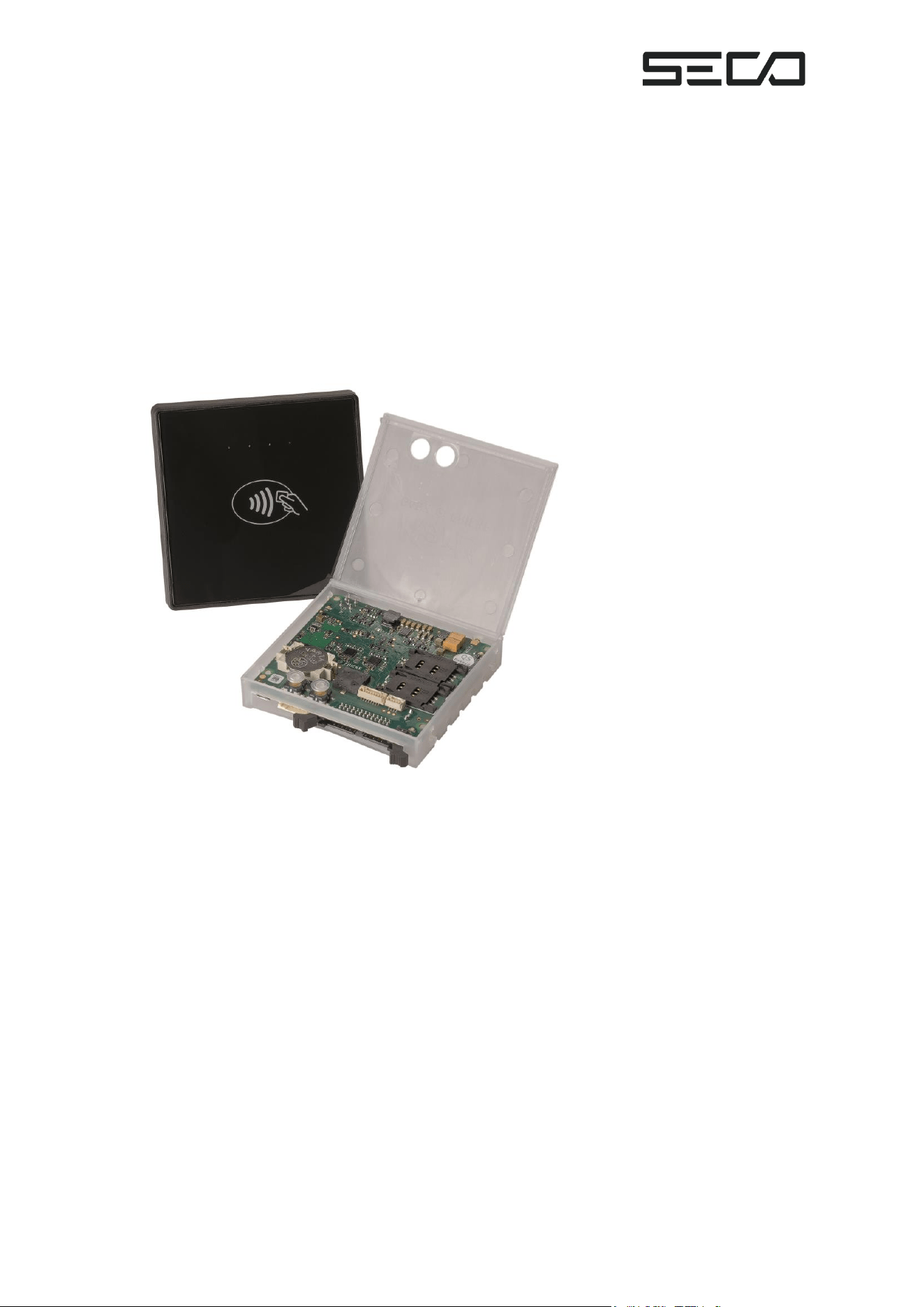
KarL4
Contactless Payment Terminal
Operating Manual
Version 2
Page 2 of 30
General Safety Instructions
The KarL4 Contactless Payment Terminal must be connected only by a qualified
electrician or technician.
Before installing the terminal, the vending machine must be disconnected from its
operating voltage. To do this, please disconnect the corresponding connection from
the battery and/or wall AC voltage.
Consult SECO if you want to make any changes or additions to the KarL4
Contactless Payment Terminal. The terminal contains components that can be
damaged or destroyed by electrostatic discharge.
Only intervene in the unit in compliance with the relevant safety measures against
electrostatic discharge (ESD) (according to EN 100015, Part 1).
Verify the supply voltage before powering the KarL4 Contactless Payment
Terminal.
Regularly update the KarL4’s software. Utilizing the latest version is the only way to
deploy the latest features and maintain cybersecurity.
KarL4
Contactless Payment Terminal
Documentation (only valid for hardware version 1.3 and software version 1.14)
Revision 2
May 13, 2026
Publisher:
SECO Northern Europe GmbH
Schlachthofstraße 20
21079 Hamburg
Phone: +49 (0)40 791 899-0
Fax: +49 (0)40 791 899-39
Email: north@seco.com
Web: www.seco.com
Page 3 of 30
Contents
General Safety Instructions ......................................................................................................... 1
Contents...................................................................................................................................... 2
1 Accessories ......................................................................................................................... 3
2 KarL4 Vending Machine Module .......................................................................................... 5
2.1.1 KarL4 Contactless Payment Terminal............................................................................ 7
3 About Contactless Payments ............................................................................................. 10
4 KarL4 Circuit Board............................................................................................................ 10
5 Assembly ........................................................................................................................... 12
6 Keys and LEDs ................................................................................................................... 15
7 Getting Started ................................................................................................................... 15
8 Maintenance ...................................................................................................................... 18
9 Service Menu ..................................................................................................................... 19
9.2.1 Terminal Time.............................................................................................................. 20
9.2.2 Terminal ID .................................................................................................................. 20
9.2.3 Serial Number ............................................................................................................. 21
9.2.4 Vending Machine Number ........................................................................................... 21
9.2.5 Dealer Card ................................................................................................................. 21
9.2.6 End of Menu ................................................................................................................ 21
9.3.1 Mobile Status .............................................................................................................. 21
9.3.2 Provider ....................................................................................................................... 22
9.3.3 Field Strength .............................................................................................................. 22
Page 4 of 30
9.3.4 IMSI ............................................................................................................................. 23
9.3.5 End of Menu ................................................................................................................ 23
9.4.1 Telemetry Started ........................................................................................................ 24
9.4.2 Telemetry Start Failed ................................................................................................. 24
9.4.3 Telemetry Successful .................................................................................................. 24
9.4.4 Telemetry Status ......................................................................................................... 24
10 Error Menu ......................................................................................................................... 25
11 Error Numbers ................................................................................................................... 26
12 REGULATORY CERTIFICATIONS ...................................................................................... 27
Page 5 of 30
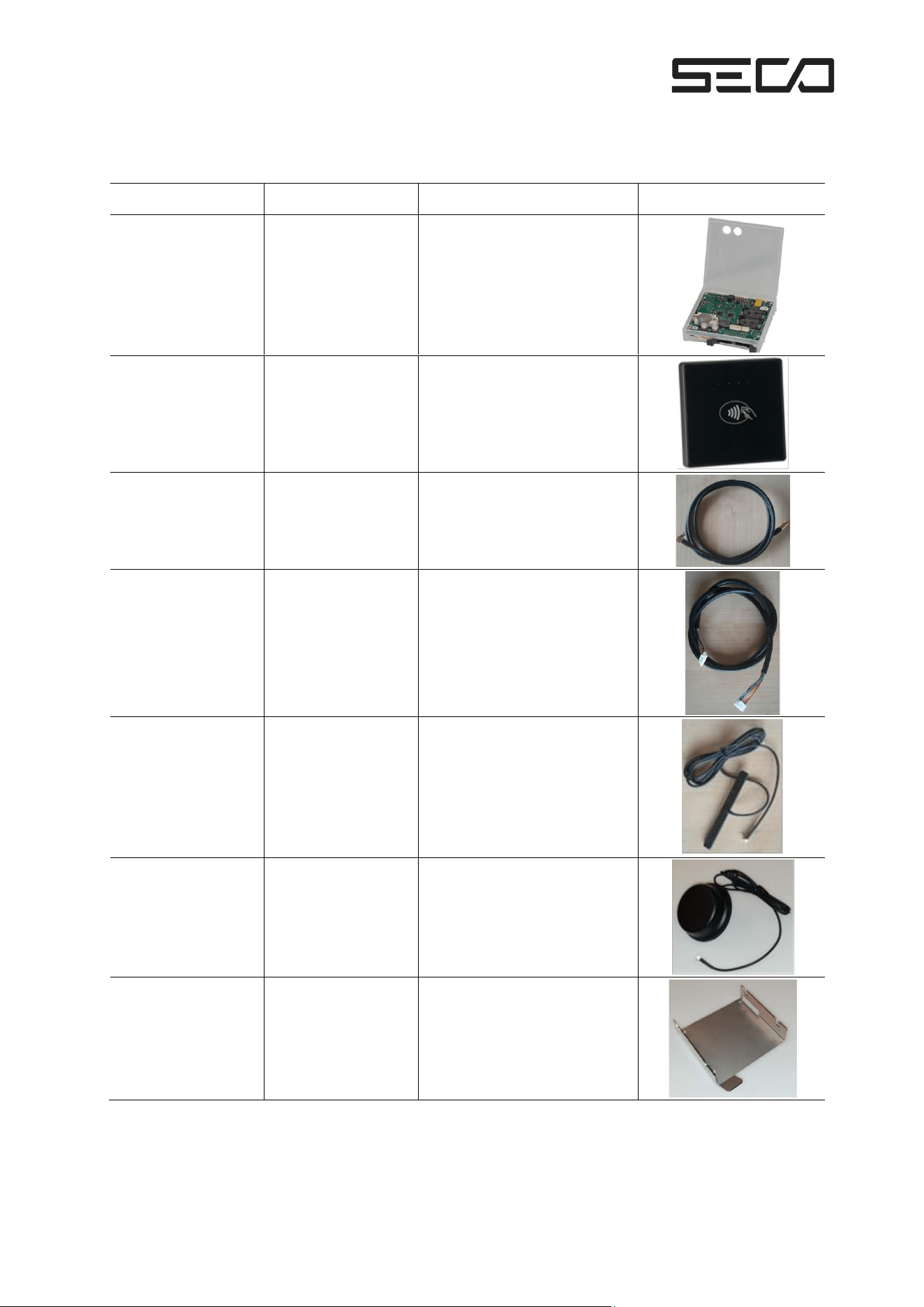
1 ACCESSORIES
The following accessories are available for the “KarL4 Contactless Payment Terminal:”
Part Number
Description
Use
Photo
903-2004R
KarL4 contactless
payment controller
Terminal electronics,
including cellular modem
903-0657R
KarL4
contactless
payment Antenna
Type C
NFC antenna for
contactless payments
921-0442R
Cable, KarL4-NFC
antenna, 80 cm
Connecting cable between
KarL4 and the NFC antenna
921-0384R
Cable, KarL4-NFC
antenna LEDs, 80
cm
Connecting cable between
KarL4 LEDs in NFC antenna
090-0995R
Antenna with
cable, LTE/GSM
700-960/1700-
2700 LC 150 cm
Mobile antenna for
mounting behind glass
(such as indoor vending
machines)
090-0899R
Antenna with
cable, LTE/GSM
700-960/1575-
2700 LC 200 cm
Mobile antenna for
mounting on metal
(such as on outdoor
vending machines)
0-0047
Mounting bracket,
KarL4 controller
Bracket for mounting the
KarL4 controller electronics
on a wall
Page 6 of 30
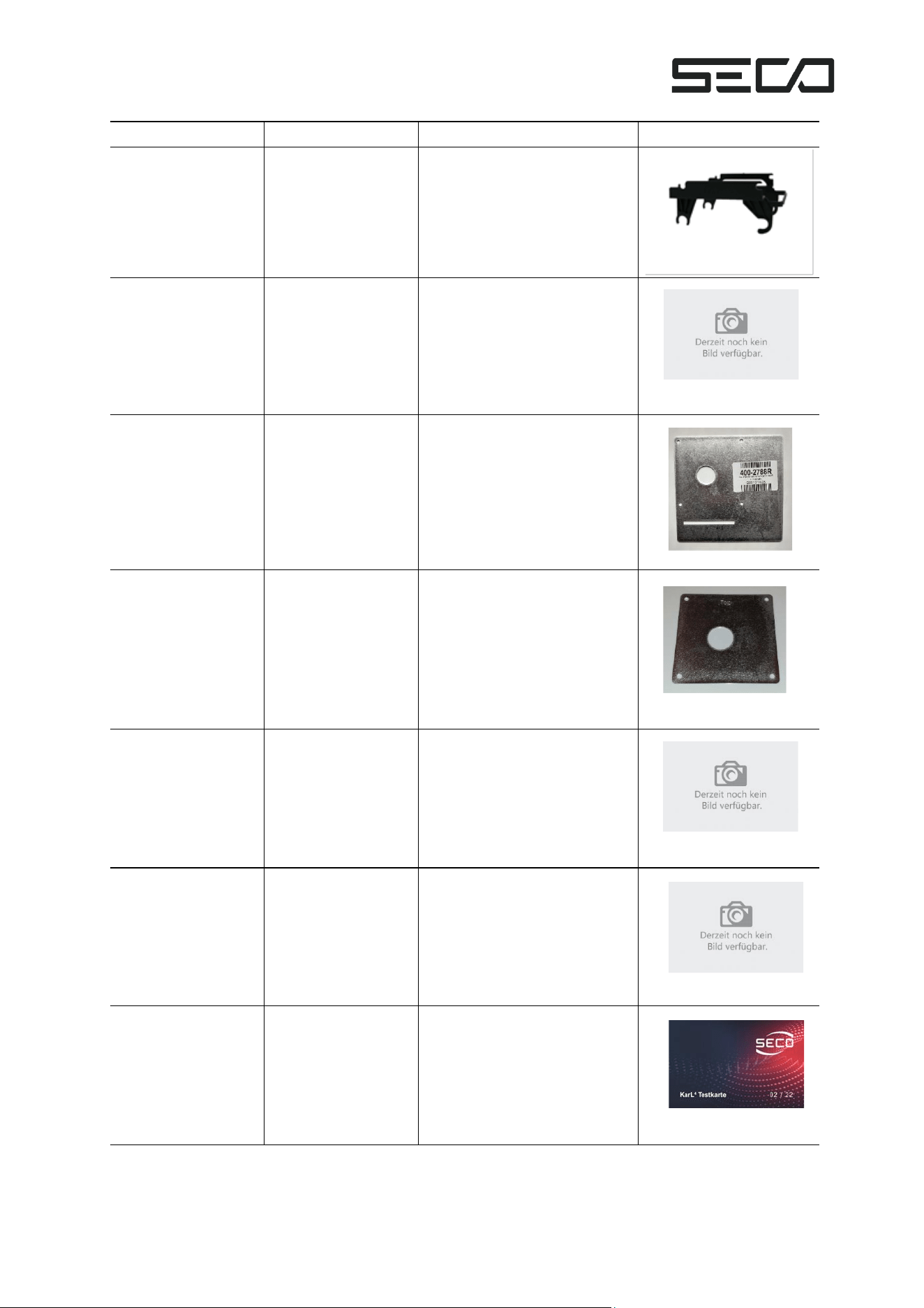
Part Number
Description
Use
Photo
400-1662R
Mounting bracket,
KarL4 with NFC
antenna
Bracket for mounting
terminal electronics on the
NFC antenna unit
400-2555R
Mounting bracket,
KarL4 with NFC
antenna
Bracket for mounting
terminal electronics on the
NFC antenna unit
400-2788R
KarL4 drilling
template for Sielaff
SCvending
machine antennas
Drilling template for
mounting the antenna
400-2577Ra
KarL4
antenna
drilling template
Drilling template for
mounting the antenna
400-2843R
Mounting adapter
for KarL4 NFC
antenna Type C
Mounting plate for the NFC
antenna in the TL Touch
400-2814R
Mounting adapter
for KarL4 NFC
Antenne Type C
Mounting plate for the NFC
antenna in the basic line
903-0677R
KarL4 contactless
payment test card
Necessary for carrying out
the KarL4 self-test
Page 7 of 30
Table 1: Accessories
2 KARL4 VENDING MACHINE MODULE
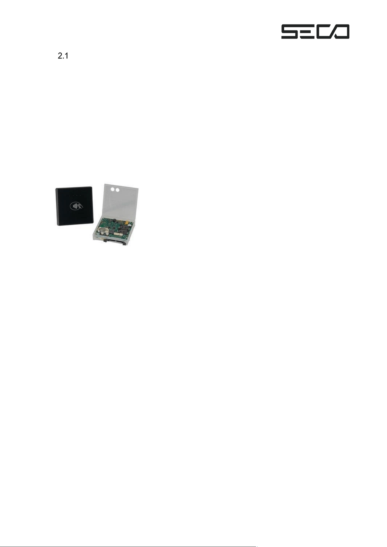
The KarL4 vending machine module is a robust, vandalism-resistant contactless payment
terminal for indoor and outdoor vending machines. With an internal processor, cellular radio, and
other connectivity options, it is a standalone payment solution that does not require an external
microprocessor running a payment software development kit with separate connectivity.
Additionally, KarL4 is designed for industry-leading energy efficiency, facilitating battery-
operated payment applications.
KarL4 is designed as an OEM solution. Utilizing the common Multidrop Bus (MDB) vending
machine interface and containing its own network connectivity, the module can be installed in
both existing and new vending machines.
KarL4 is our innovation for contactless payment with credit cards, including Mastercard, Visa,
and girocard – depending on geographical deployment location. It is a terminal without a PIN
pad (TOPP), and optionally allows also quick age verification in Germany. KarL4 uses Near Field
Communication (NFC) for payment card data transmission.
Currently, KarL4 is certified for use as follows:
Geography
Payment Cards
Maximum
Transaction
Certifications
Germany
girocard, smart cards according to ISO
14443 A&B, NFC
€50
United
States
Mastercard, Visa
$50
PCI level 3, FCC
The KarL4 terminal electronics is housed in a robust plastic casing that can be installed on a
suitable holder using the snap-on method. The NFC antenna is mounted separately from the
electronics on the front of the vending machine. It may be mounted behind a glass front in
certain scenarios.
KarL4 can be connected via MDB to a vending machine controller, and is backwards compatible
with KarL2 and KarL3.
Connection via USB is possible but not yet enabled in software.
Page 8 of 30
Variants
2.1.1 KarL4 Contactless Payment Terminal
As a rule, girocards are equipped with a contactless interface. For payment and age verification
with such cards, it is sufficient to hold them in front of the NFC antenna.
The heart of the system is formed by the KarL4 payment terminal, which comes in a compact
plastic housing and can be connected to a controller via USB (pending software release) or
MDB.
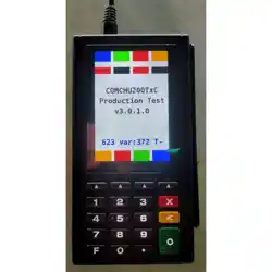
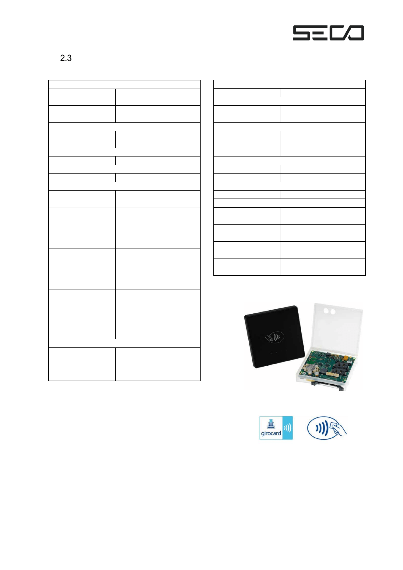
The KarL4 contactless payment terminal consists of the KarL4 contactless payment controller
and an NFC antenna.
The NFC antenna is designed to be mounted on the front of a metal vending machine housing.
Figure 1 – KarL4 contactless terminal

Page 9 of 30
Vending Machine Interface
Communication with the vending machine control is via MDB (Multi Drop Bus).
The KarL4 is compliant with the latest MDB specification version 4.3 from July 2019, provided by
the National Automatic Merchandising Association (NAMA) and located here:
https://www.namanow.org/wp-content/uploads/Multi-Drop-Bus-and-Internal-Communication-
Protocol.pdf
KarL4 provides the MDB interface signals on a size-optimized connector and utilizes an external
adapter cable to plug into the standard MDB connector.
In battery mode, the KarL4 activates the vending machine by placing a card on the NFC antenna
or by inserting a card into the card reader module.
Page 10 of 30
Specifications
Payment Card Interfaces
Customer Card
Contactless
ISO 18092 (NFC)
Data Transmission
Cellular radio (Quectel EG-
91 series)
RTC & Tamper Protection
Battery buffered
Software Updates
Via cellular radio
Interfaces
Vending Machine
Controller
MDB/IPC Level 02/03
(optional USB)
Cellular radios
Europe: Quectel EG91
series
US: Quectel EG91-NAX,
FCC ID
XMR2020008EG91NAXD
Cardholder
NFC antenna
4 LED status (green)
Display Vending Machine
Acoustic signal transmitter
Service technician
2 keys - service menu
2 LEDs for controller
status(red / green)
1 LED modem status
(green)
1 LED NFC status (red)
Extensions
MDB Master
To connect to:
MDB display,
MDB bill validator
MDB coin changer
Power Supply
8.0 to 42.5 VDC
Power Consumption
Stand-By
typ. 2.5 mA (@ 13.8V)
Operation
typ. 125 mA (@ 13.8V)
Environmental conditions
Operating
Temperature
-25 to +70 °C
Humidity
Up to 100%
Dimensions
Terminal Electronics
85 x 90 x 18 mm (LxWxH)
NFC Antenna
98 x 98 x 13 mm (LxWxH)
Battery
Coin cell
Lithium Battery (CR2032)
Connectors
MDB-Slave
JST S7B-PH-SM4-TB
MDB-Master
JST S6B-PH-SM4-TB
Card Reader
AMC170F-26POL
USB-OTG
USB Micro-AB
Antenna - NFC
MCX
LED NFC
JST SM12B-GHS-TB
Antenna - Cellular
Modem
MMCX
Figure 3 – KarL4 Technical data

3 ABOUT CONTACTLESS PAYMENTS
Contactless payment describes payments using Near Field Communication technology (NFC).
This kind of payment today is supported by most common payment cards, e.g. credit cards and
also more localized solutions like the girocard in Germany (formerly EC card), state-of-the-art
smartphones, and point-of-sale (POS) terminals. NFC technology, which makes secure
contactless payment possible, is the linchpin for new applications that makes payment cards
even smarter and more convenient.
▪ Just hold it close to the payment terminal and you’re done!
▪ The payment process is reduced to seconds.
▪ Amounts of up to 50 Euros can usually be paid without PIN or signature in Europe.
Payment transactions that do not require the entry of a PIN are especially common in vending
and ticketing machines due to the small amounts of money involved.
The easy payment process with a Terminal without PIN pad
The payment process is started by placing the card or smartphone on the NFC antenna.
Payment is made without authorization. Neither a PIN nor a signature is required. The payment
process is controlled by the risk management of the card, either offline or online. In the case of
online payment, the card is checked beforehand via the bank’s authorization system.
The KarL4 contactless payment terminal stores the data associated with each transaction, and
passes it on online as quickly as possible for further processing by banking systems. As a rule,
the cardholder’s account is debited and the amount is credited to the dealer’s account the day
after the payment. The dealer’s account is credited as a collective transfer of all the dealer’s
terminals and all transactions of a given day.
Page 12 of 30
4 KARL4 CIRCUIT BOARD
Front
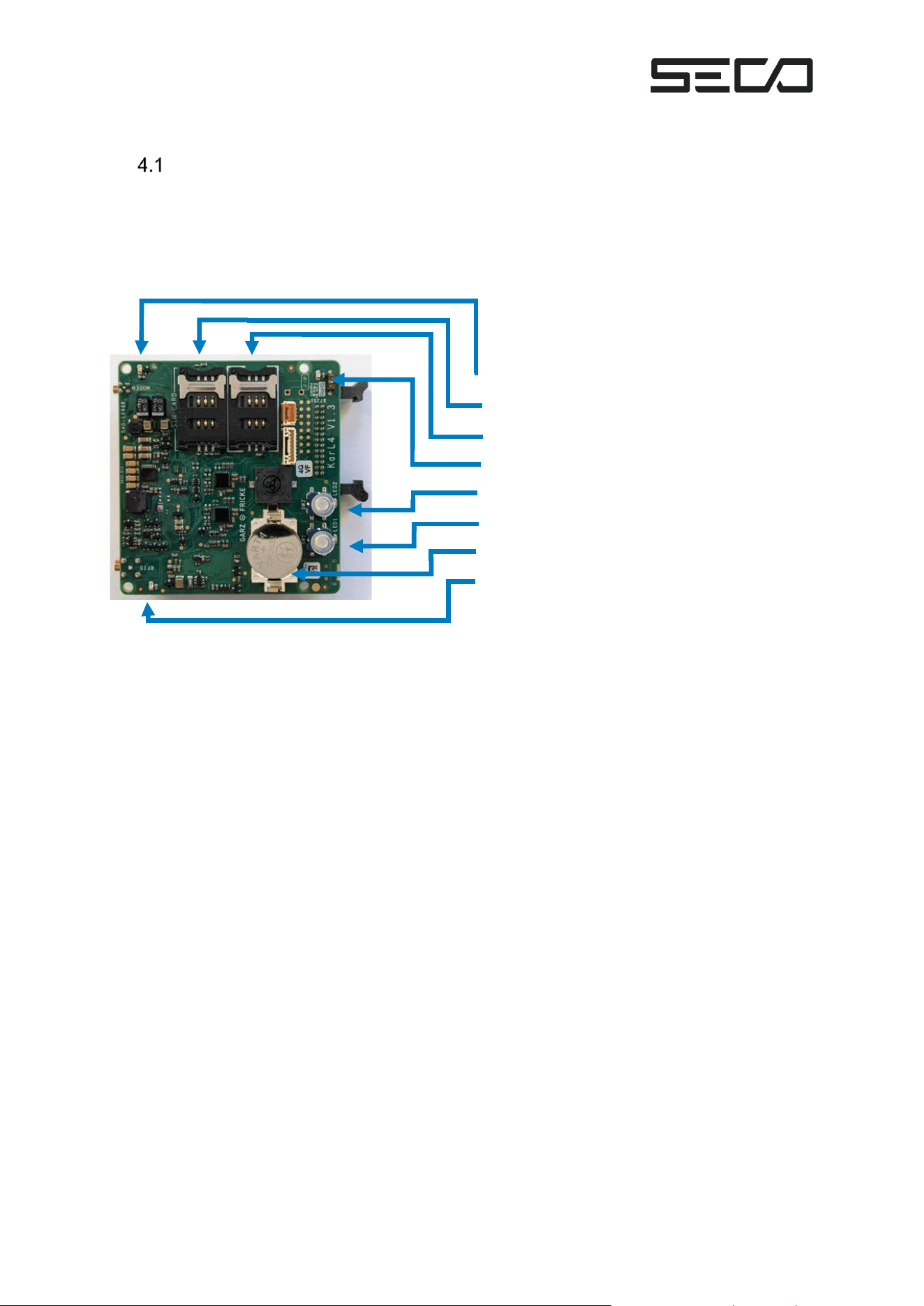
The vending machine module is equipped with 2 keys and 2 LEDs (red and green). This allows a
service technician to see the operating status of the terminal and make adjustments if
necessary.
The arrangement of the keys, LEDs, and card slots is shown below:
The system has two slots for chip cards: one slot for the dealer card and one slot for an optional
SIM card for mobile communications. A SIM card is not required; each off-the-shelf KarL4 device
is shipped with an activated SIM chip.
Figure 4 – Front view of KarL4
Modem status LED (green)
Plug-in slot for SIM-card (currently not necessary)
Plug-in slot for dealer card
Test mode status LED (yellow, on = in test mode)
S2 and red LED
S1 and green LED
Backup battery
Status LED (red)
Page 13 of 30
Back
MODEM
MDB-MASTER
BT
RFID LEDS
RFID ANT
READER
MDB-SLAVE
Figure 4 – Back view of KarL4
Page 14 of 30
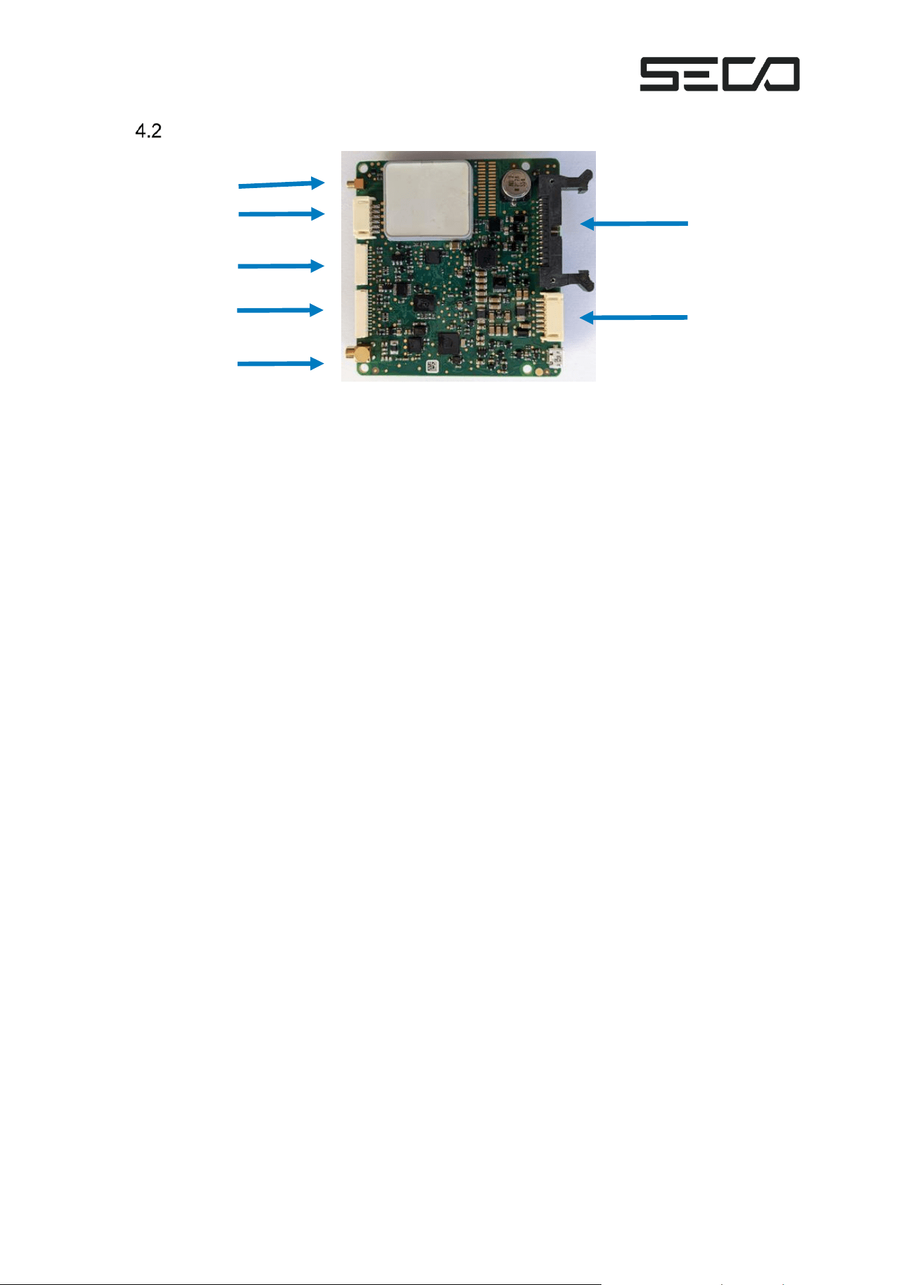
KarL4 offers the following connection options to external components. The designations of the
connections are stamped on the housing.
Name
Function
Ref
#
#
Pins
KarL4
connector
Mating
connector
MDB-
SLAVE
Connection to the vending machine for
input power supply and for
communication with the vending
machine controller (via MDB)
JST S7B-
PH-SM4-TB
MDB-
MASTER
Connection for MDB periphery (e.g.,
LCD)
12
JST S6B-
PH-SM4-TB
Antenna -
NFC
MCX
LED NFC
JST
SM12B-
GHS-TB
MODEM
Connection to cellular antenna
MMCX
“
5 ASSEMBLY
Installation of Terminal Electronics
The KarL4 terminal electronics are mechanically compatible with KarL2 and KarL3 payment
terminals. Brackets that have already been installed can still be used.
▪ To upgrade an existing KarL2 or KarL3 payment terminal, disconnect all connection
cables on the old termina and remove the terminal electronics from the bracket.
▪ Insert the KarL4 terminal electronics into the bracket.
▪ Connect the MDB connection cable with KarL4.
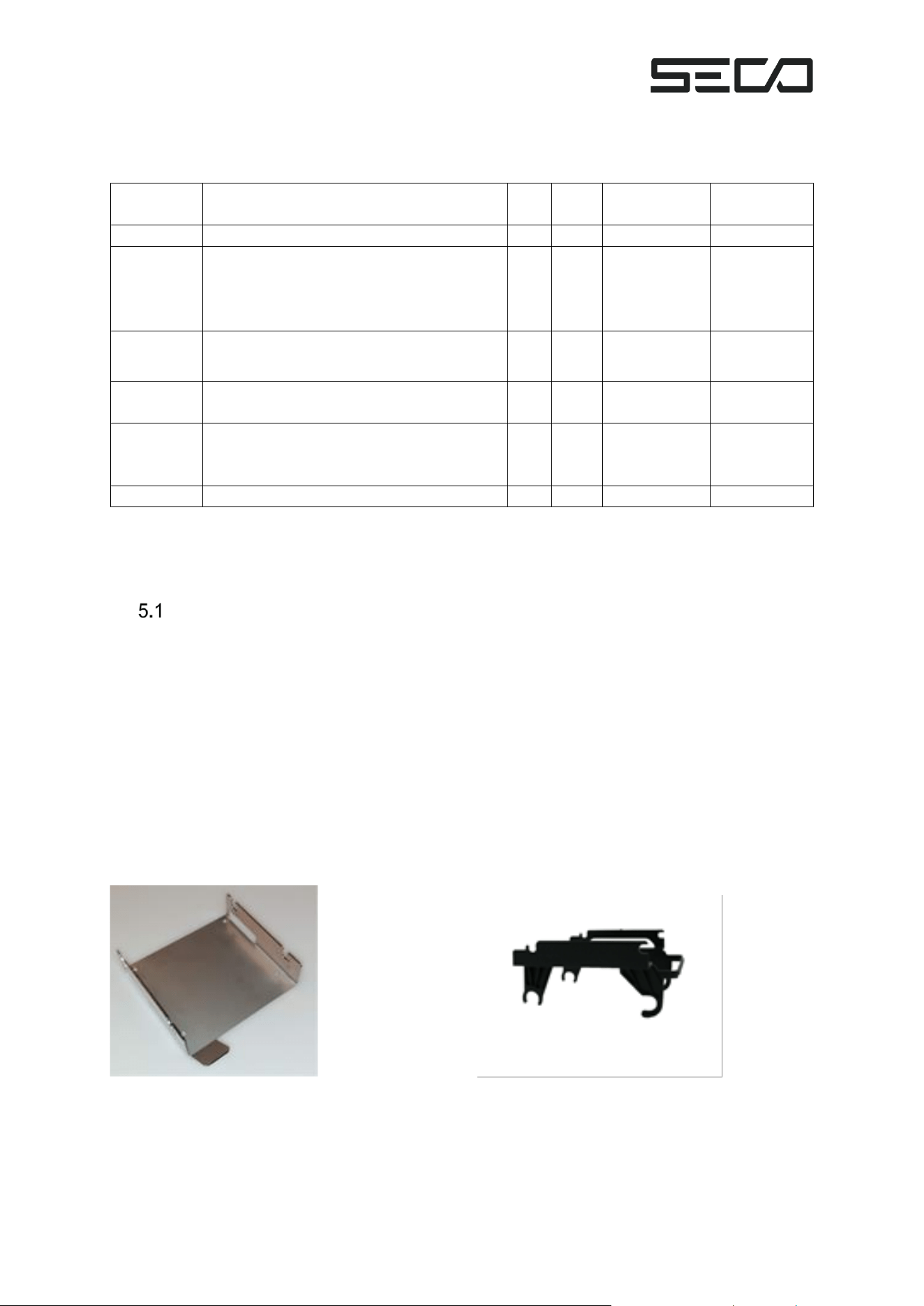
Brackets available for the terminal electronics:
Bracket for wall mounting Bracket for mounting on contact unit
Figure 6 – Bracket for wall mounting
Figure 7 – Bracket for mounting on contact unit
Page 15 of 30
Installing the NFC Antenna
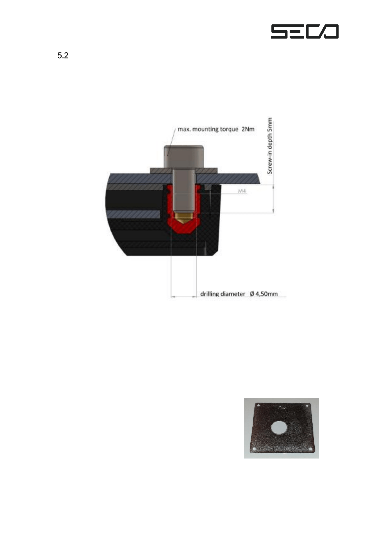
The NFC antenna is suitable for installation behind a glass front as well as for mounting on the
outer surface of a vending machine door. The antenna is fixed with four M4 screws. The length
of the screws depends on the wall thickness of the vending machine door. The screws must not
penetrate deeper than 5 mm into the threaded bushes of the NFC antenna.
A length of 8 mm should generally suffice.
The screws are not included with the NFC antenna.
Appropriate holes (4x 5.5 mm and 1x 25 mm) must be drilled in the vending machine door for
the fastening screws and for the cable feed-through. Two drilling templates are available to
make this easier:
▪ KarL4 standard drilling template (Art. no. 400-2577Ra)
This template has the same outer diameters as the
antenna itself and can therefore always be used,
especially where only limited space is available for
mounting the antenna.
Figure 8 – NFC antenna
Figure 9 – Standard drilling template
Page 16 of 30
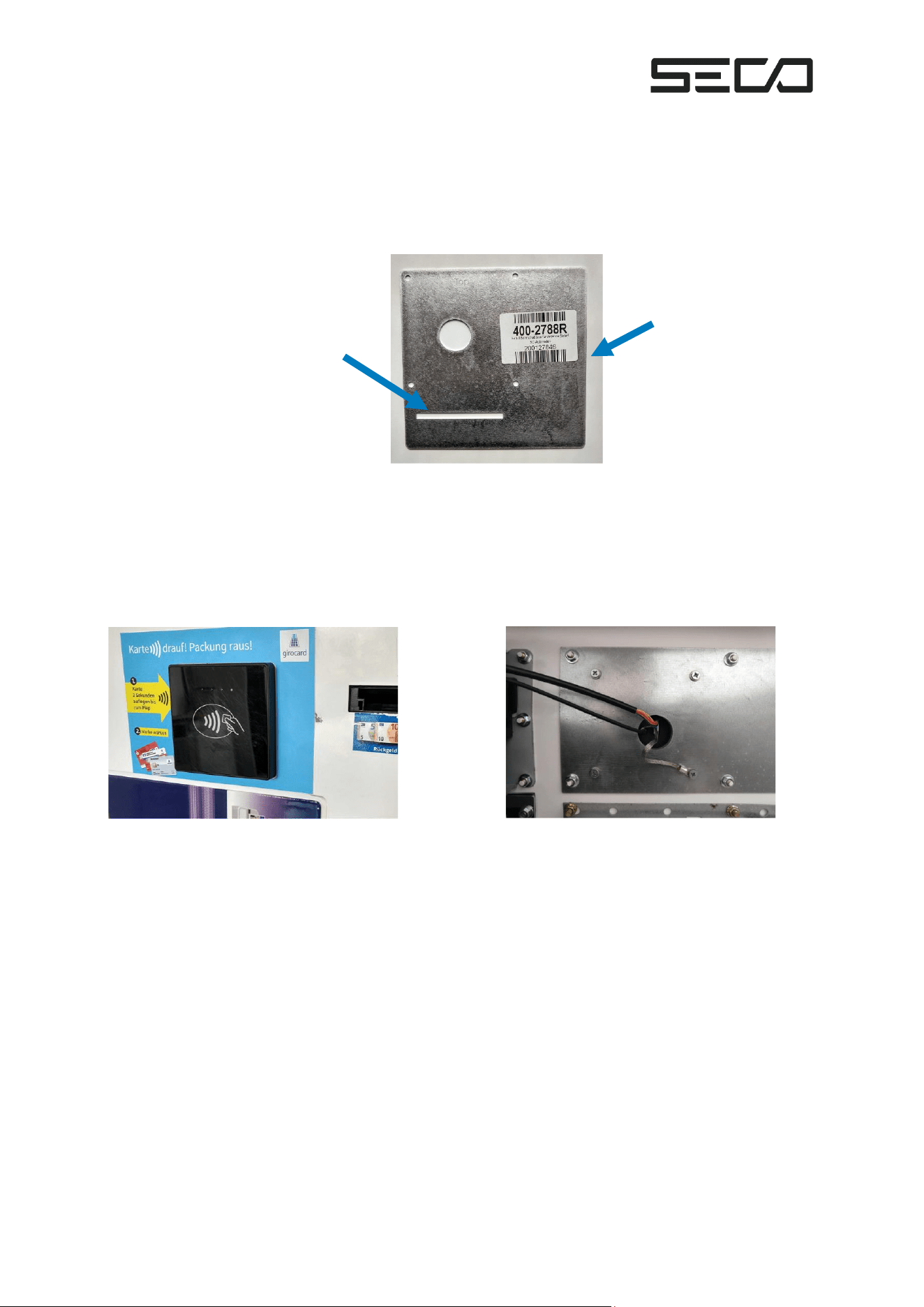
▪ KarL4 drilling template Sielaff SC (Art. no. 400-2788R)
This is a template specially designed for Sielaff SC vending machines. The contact edges
to be used are the decorative panel and the advertising panel on the vending machine
door. Using the template not only ensures the correct positioning of the holes in relation
to each other but also the correct position of the antenna itself.
Contact edge for
Contact edge for right edge of
top edge of advertising panel decorative panel
After mounting the NFC antenna with the 4 screws, the various cables are connected and laid.
The earthing lug of one of the antenna cables must be connected to the housing of the vending
machine in an electrically conductive manner.
Finally, the label for operator guidance is attached to the front of the door.
Figure 11 – Front of vending machine door
Figure 12 – Back of vending machine door
Figure 10 – Sielaff drilling template
Page 17 of 30
Installing the Mobile Antenna
Two different mobile antennae are available:
Planar antenna:
▪ For use outdoors
▪ For mounting on sheet metal
▪ Ideally, for mounting on the top of the vending machine housing
Adhesive antenna:
▪ For use indoors
▪ For mounting behind glass or plastic
6 KEYS AND LEDS
Key Function
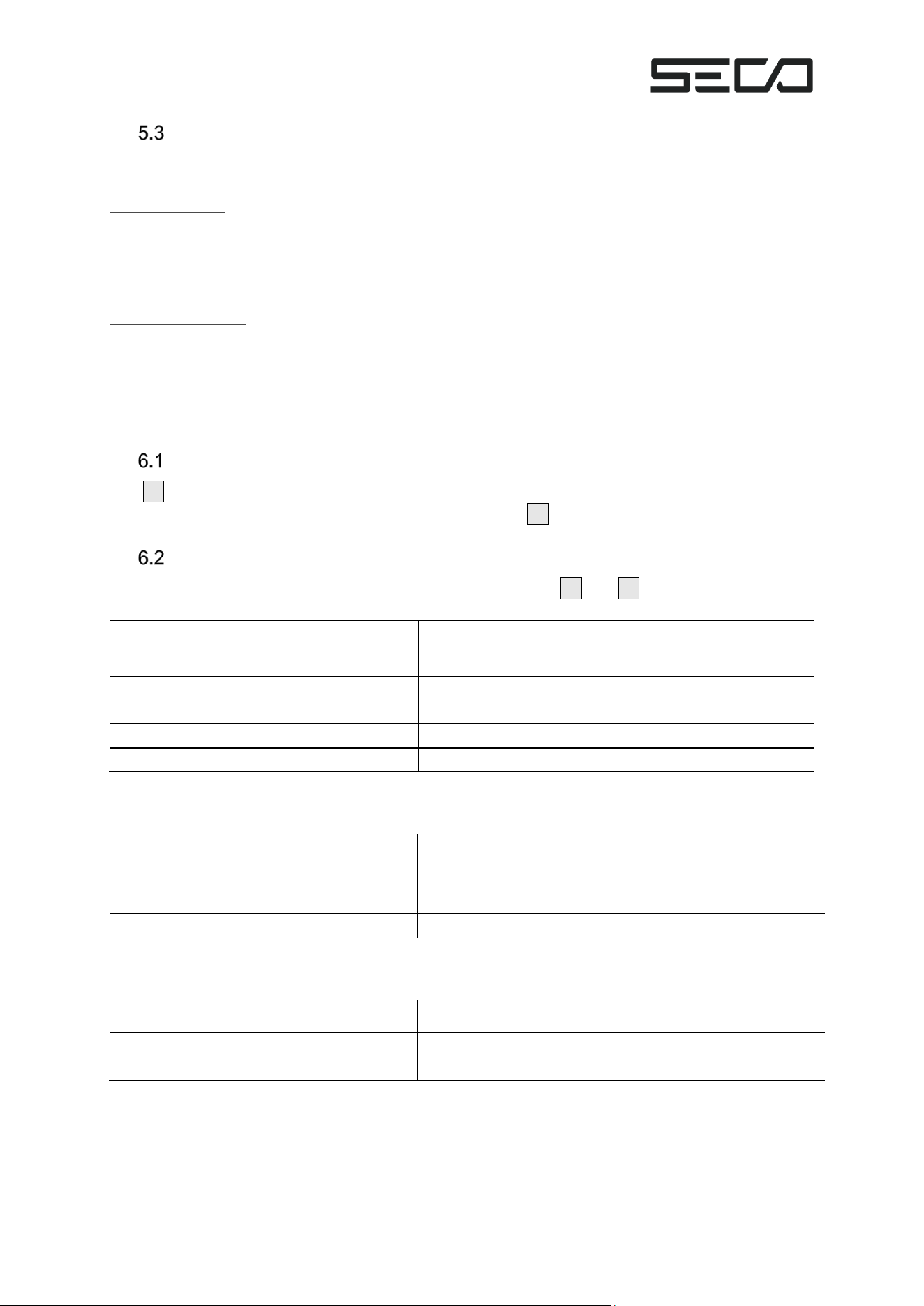
The S1 key (see Figure 4) takes you to the service menu and then to the next menu item.
The menu item shown can be processed by pressing the S2 key.
Significance of LEDs
The terminal operating status is indicated by the LEDS on the S1 and S2 keys (see Figure 4).
Red LED
Green LED
Significance
Off
Off
Idle state, terminal is switched off
Off
On
Terminal ready for operation, no errors
On
On
Firmware signature successfully checked, update active
Flashing
Off
Terminal out of order, Firmware signature incorrect
Flashing
On
Terminal out of order, tampered
The status of the mobile connection is indicated by a green LED in the area of the mobile
antenna connection:
LED modem status
Significance
Off
Modem switched off
Flashing fast
Network search
Flashing, off longer than on
Modem is registered in network
The status of the NFC reader is indicated by a red LED in the area of the NFC antenna
connection:
LED NFC
Significance
Off
Operational
On
Overcurrent protection tripped
Page 18 of 30
7 GETTING STARTED
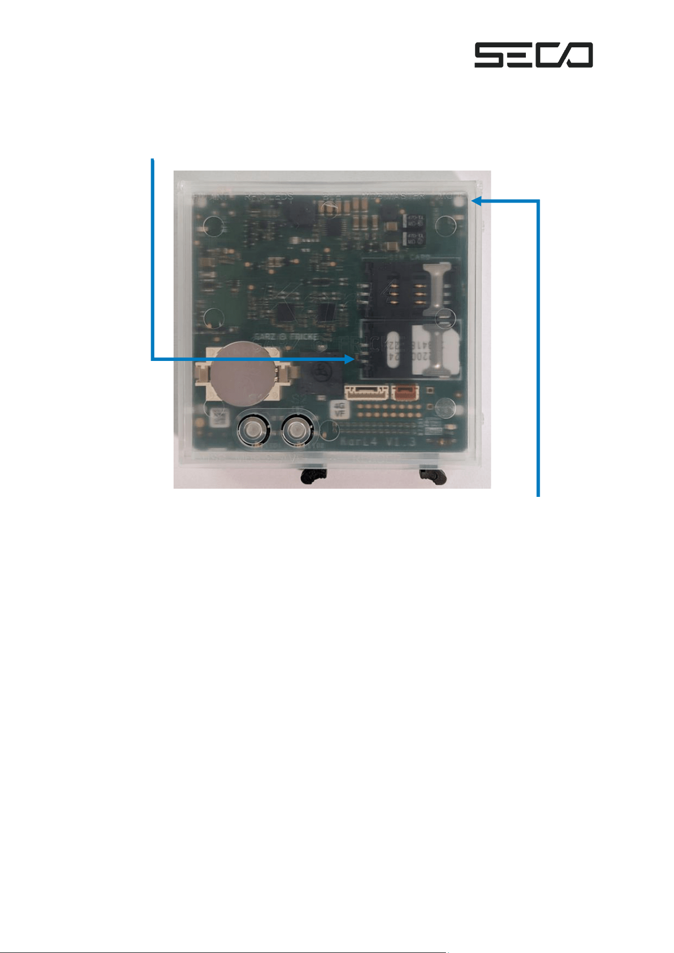
▪ A SIM card is not required as the KarL4 is fitted with a SIM chip.
LED modem
status (green)
▪ Connect the NFC antenna
▪ Connect the cellular antenna
▪ Connect to other devices, such as MDB devices
▪ Switch on the vending machine
▪ Cellular connection is established if it beeps twice after switching on and the green
modem status modem status LED is on longer than it is off.
▪ Start telemetry via the KarL4 service menu. This will assign a terminal ID to the unit, load
an EMC configuration, and update it if necessary.
Figure 13 – KarL4 within the case
Page 19 of 30
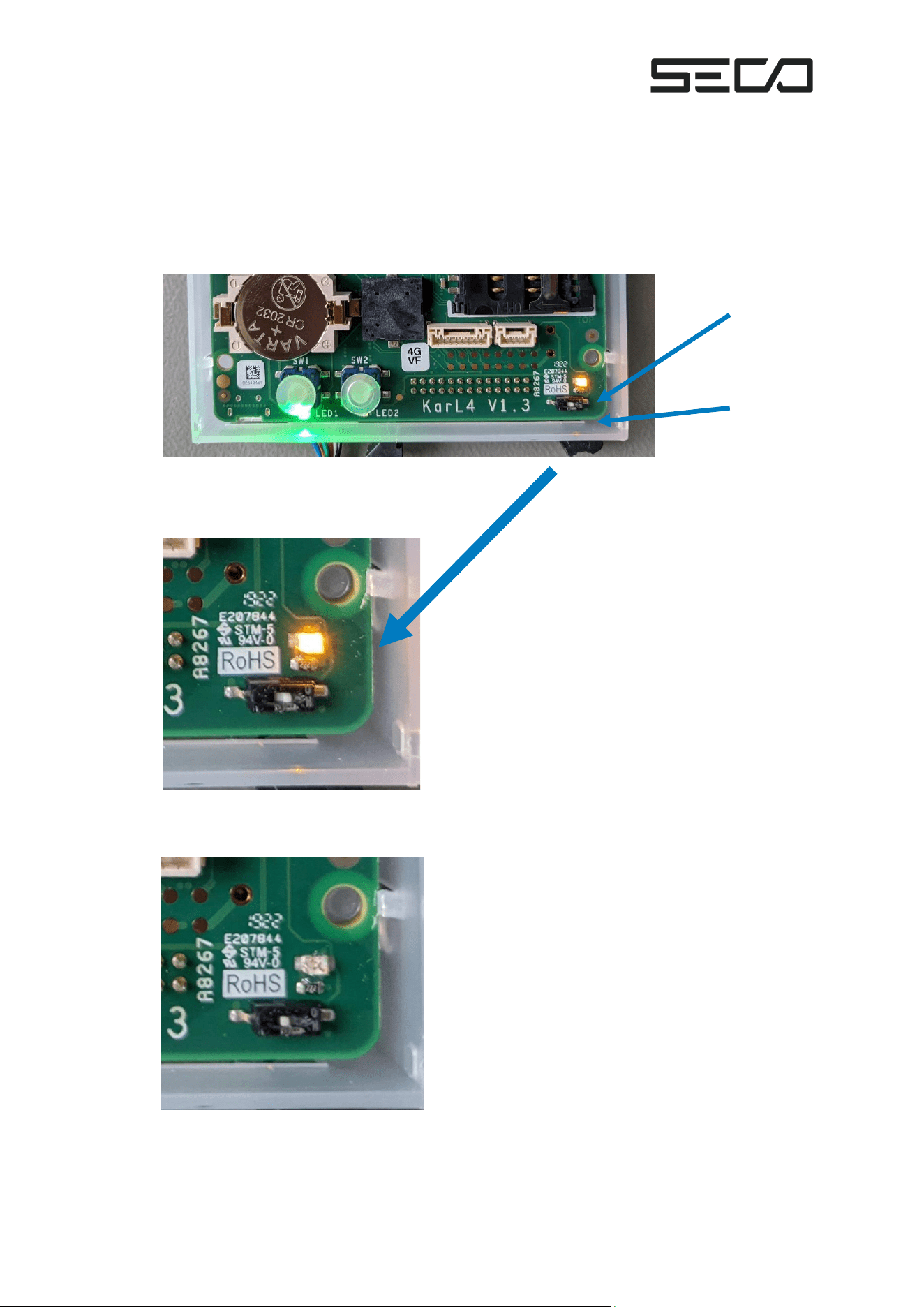
▪ Check the position of the debug switch:
The debug switch is required for development and functional tests after production.
When deployed in a product, this switch must be in the “off” position so that the KarL4
does not utilize unnecessary power. The adjacent yellow LED must not light up; being lit
indicates the switch is in the on (debug) position.
Incorrect switch position: Switch on right, yellow LED lights up:
Yellow
LED
Debug
switch
Correct switch position: Switch on left, yellow LED does not light up:
Figure 14 – Incorrect switch position
Figure 15 – Enlarged view of the incorrect switch position
Figure 16 – Correct switch position
Page 20 of 30
Functional Test without Test Card
▪ Check via the KarL4 service menu whether the machine has received a terminal ID
(display machine data).
▪ The machine is in the basic state, in sleep mode in battery operation, and in idle mode in
mains operation:
o Place the girocard on the NFC antenna.
▪ A battery-operated vending machine is activated.
▪ The maximum sales price is reserved and is available for a sale.
o Cancel the transaction by pressing the return key.
▪ The reserved amount is cancelled.
8 MAINTENANCE
Battery/Coin Cell
The coin cell battery on the KarL4 is necessary for maintaining the date and time as well as for
protecting the digital keys. Changing the battery must always be done with another source of
power enabled to the KarL4 payment terminal. Such power sources include:
• Power provided to the KarL4’s MDB port
• The battery plugged in.
Page 21 of 30
Software Updates
SECO automatically provides software updates to each KarL4 payment via SECO’s terminal
management system. Updates are provided via the cellular modem and immediately installed.
The terminal operator does not need to take any action for maintaining KarL4 software.
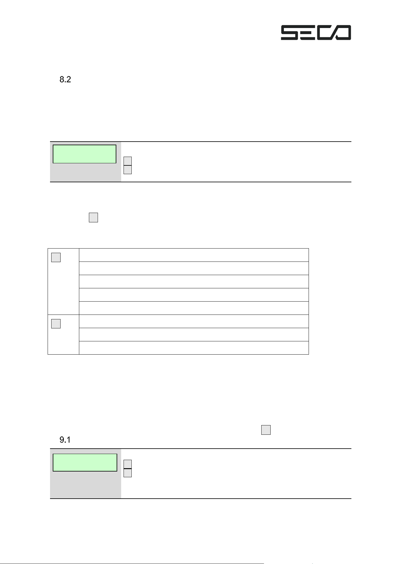
However, it is possible to search for and perform updates manually via the service menu:
Find updates.
S1 – Next menu item
S2 – Start update search
9 SERVICE MENU
Pressing the S1 key or opening the machine door takes you to the service menu. Information is
shown on the display of the vending machine and settings can be made.
The keys generally have the following functions:
S1
Access to the service menu after opening the door
Calling up the next menu item within the respective menu
Acceptance of a value edited with S2
In editing mode, switch to the next editable value
In submenu, press and hold to exit the submenu
S2
Switching from the service menu to editing mode
Changing values in editing mode
At the end of the main menu, call up the service menu again
In the service menu, each menu item can be accessed using the two keys and – if provided –
the corresponding menu item can be changed.
The individual menu items of the service menu are also accessed automatically. This happens at
intervals of 5 seconds, after which the next menu item is called up.
After the last menu item has been called up, the service menu is automatically closed if no user
entries are made. If the service menu has been exited by the automatic switch-off when the door
was open, the service menu can be called up again by pressing the S1 key.
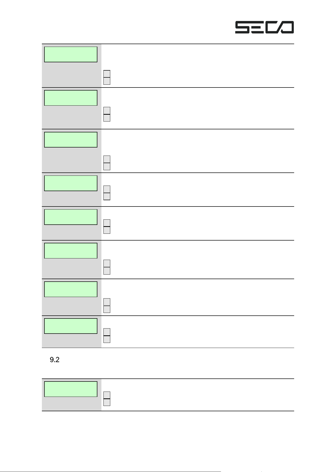
Service Menu - Main menu
Information on terminal software version.
S1 – Next menu item
S2 – N/A
If no key is pressed, the system switches to the next menu item after 5
seconds. Applies for all menu items.
Check for
new software
KarL4 Service
1.14.0.5021
Page 22 of 30
Display submenu for information about the machine.
Contains information on terminal time, terminal ID, serial number, machine
number, and dealer card.
S1 – Next menu item
S2 – Switch to the device data submenu
Show information about the mobile connection.
Contains information on the service provider, signal strength, and IMSI.
S1 – Next menu item
S2 – Switch to the mobile info submenu
Start telemetry manually.
Telemetry is used to transmit cash register and configuration data as well as
for remote maintenance through updates or configurations.
S1 – Next menu item
S2 – Starts telemetry. See telemetry
Find updates.
S1 – Next menu item
S2 – Start update search. See telemetry
Start day closing manually.
S1 – Next menu item
S2 – Starts day closing. See day closing
Start EMC diagnosis manually.
Tests NFC antenna and MDB connection.
S1 – Next menu item
S2 – Starts EMC diagnosis. See EMC diagnosis
Start EMC diagnosis manually.
Tests the mobile connection.
S1 – Next menu item
S2 – Starts network diagnosis. See network diagnosis
End of main menu.
S1 – Exit menu
S2 – Start at beginning
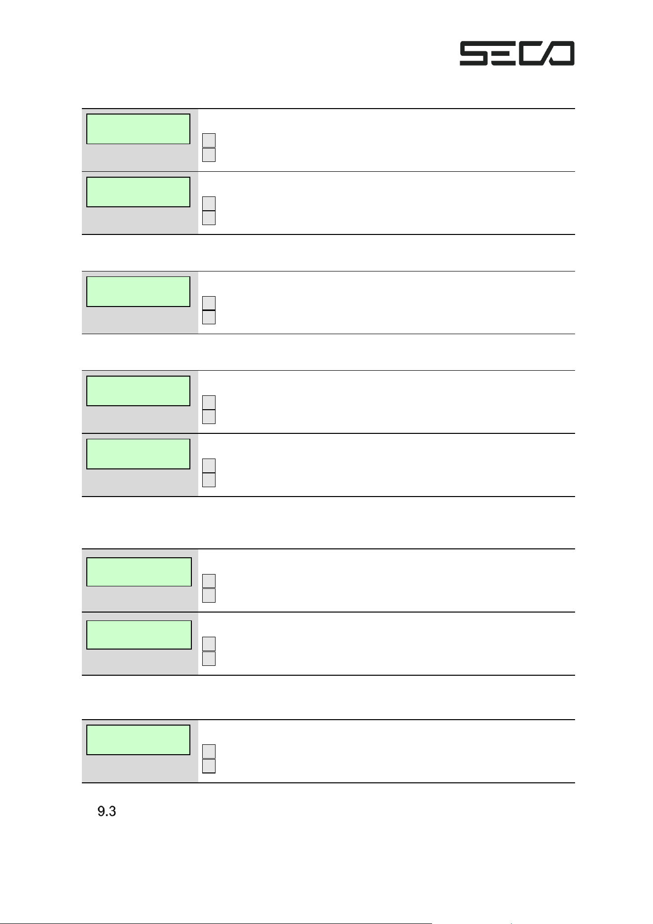
Machine Data Submenu
9.2.1 Terminal Time
The current time and date are shown.
S1 – Next menu item
S2 –
Deviceinfo
show
Mobile Net Info
start
Telemetry
start
Terminal Time:
00:00 01.01.2022
Day Close
start
EMV-Diagnosis
start
Net.-Diagnosis
start
END --> SW1
CONTINUE --> SW2
Check for
new software
Page 23 of 30
9.2.2 Terminal ID
Display if a terminal ID is available.
S1 – Next menu item
S2 –
Display if a terminal ID is not available.
S1 – Next menu item
S2 –
9.2.3 Serial Number
The serial number is shown.
S1 – Next menu item
S2 –
9.2.4 Vending Machine Number
The vending machine number is displayed if available.
S1 – Next menu item
S2 –
Display if no vending machine number is available.
S1 – Next menu item
S2 –
9.2.5 Dealer Card
If a dealer card is present, its number and expiry month are displayed.
S1 – Next menu item
S2 –
Display if no dealer card is available.
S1 – Next menu item
S2 –
9.2.6 End of Menu
End of submenu.
S1 – Exit menu. Back to main menu
S2 – Start at beginning
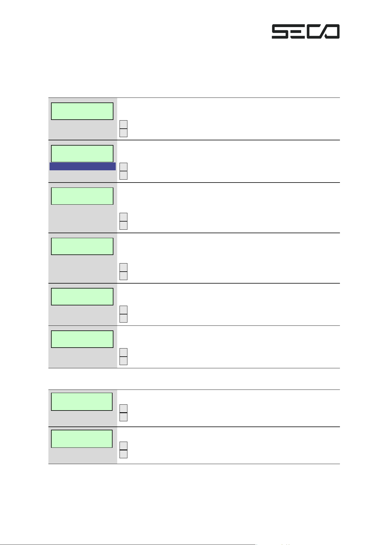
Mobile Data Submenu
9.3.1 Mobile Status
The current mobile status is displayed. Possible:
▪ No network
Terminal-ID:
0000000000000001
Terminal-ID:
not set
Serial number:
1000000000000000
Machine No.
0000000000100000
Machine No.
not available
DC-No:0000055149
expiry: 12/2024
Dealer Card
not
END --> SW1
CONTINUE --> SW2
Page 24 of 30
▪ Network search
▪ Logged in
▪ Roaming
▪ Login rejected
▪ Unknown (error)
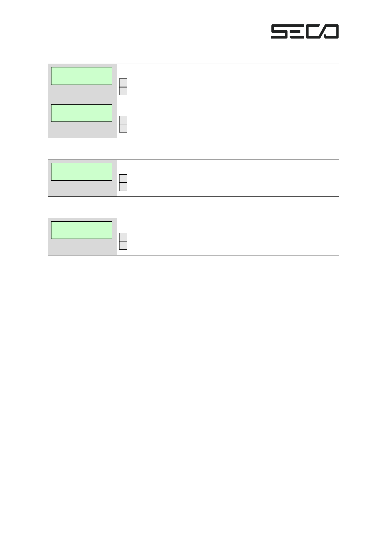
Mobile status: no network available.
Unable to find a network.
S1 – Next menu item
S2 –
ams
Mobile status: network search.
Searching for a network.
S1 – Next menu item
S2 –
Mobile status: logged in.
The network technology used is also displayed. Possible:
GSM, GPRS, LTE
S1 – Next menu item
S2 –
Mobile status: logged into foreign network (roaming).
The network technology used is also displayed. Possible:
GSM, GPRS, LTE
S1 – Next menu item
S2 –
Mobile status login rejected.
Login to a mobile network was rejected.
S1 – Next menu item
S2 –
Unknown mobile status/Error.
Contains the mobile status error code in brackets.
S1 – Next menu item
S2 –
9.3.2 Provider
Name of mobile provider is displayed, if available.
S1 – Next menu item
S2 –
Display if mobile provider is missing/invalid.
S1 – Next menu item
S2 –
Mobile Net Stat.
No Network
Mobile Net Stat.
Network Search
Mobile Net Stat.
Roaming LTE
Mobile Net Stat.
regist. in LTE
Mobile Net Stat.
Reg. denied
Mobile Net Stat.
unknown (XX)
Mobile Net Prov.
Name of Provider
Mobile Net Prov.
Not available
Page 25 of 30
9.3.3 Field Strength
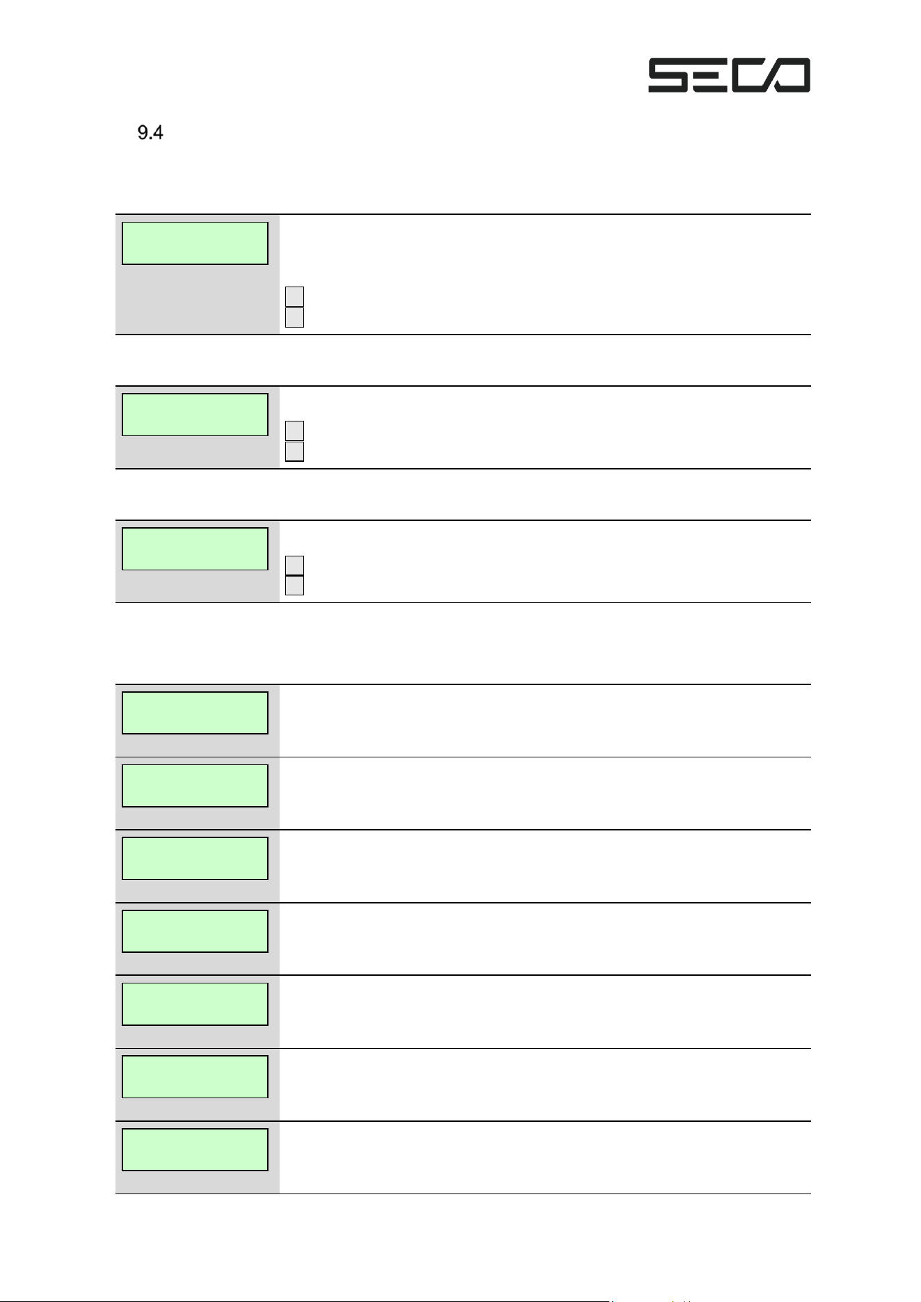
Field strength of mobile network is displayed, if available.
S1 – Next menu item
S2 –
Display if mobile network is missing/invalid.
S1 – Next menu item
S2 –
9.3.4 IMSI
The IMSI is shown.
S1 – Next menu item
S2 –
9.3.5 End of Menu
End of submenu.
S1 – Exit menu. Back to main menu
S2 – Start at beginning
Mobile Net Sig.
-100dBm
Mobile Net Sig.
Not available
Mobile Net IMSI
0000000000000011
END --> SW1
CONTINUE --> SW2
Page 26 of 30
Telemetry/Update Search
The update search is a special form of telemetry and is therefore not explained separately.
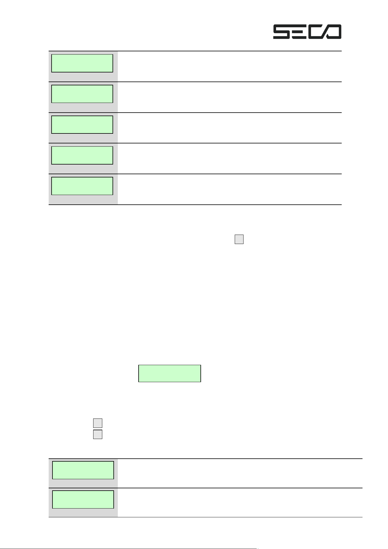
9.4.1 Telemetry Started
Telemetry has been started. This display disappears automatically. During the
telemetry/update search, there are further screen outputs. If successful,
continue with telemetry.
S1 –
S2 –
9.4.2 Telemetry Start Failed
Unable to start telemetry.
S1 – Next menu item. Main menu
S2 –
9.4.3 Telemetry Successful
Telemetry was carried out successfully.
S1 – Next menu item. Main menu
S2 –
9.4.4 Telemetry Status
During telemetry, various screen outputs appear. These are listed as follows:
Telemetry is active. No specific task is executed.
EVA-DTS list XXX is received.
EVA-DTS list XXX is being sent.
File YYY is received.
Unable to reach host.
Telemetry failed with error code 0xHH.
The telemetry has been rejected.
Telemetry
started
Telemetry
start failed
Telemetry
successful
Telemetry
running
Telemetry
Rcv Lst XXX
Telemetry
Snd Lst XXX
Telemetry
Rcv File YYY
Telemetry
host unavailable
Telemetry
error: 0xHH
Telemetry
contact declined
Page 27 of 30
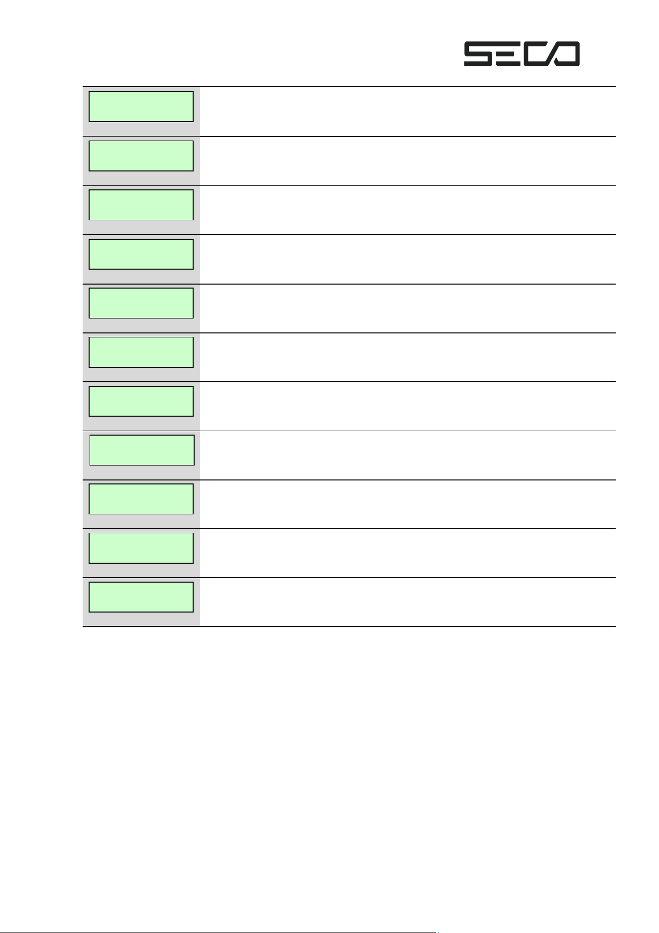
An update was started.
The update found is invalid and will not be carried out.
The update found could not be read. No update will be carried out.
The update found is too old. No update will be carried out.
The telemetry session carried out was successfully completed
10 ERROR MENU
After opening the vending machine door or after pressing the S1 key, a self-test is carried out in
KarL4. To be tested:
▪ Triggering hardware security
▪ Terminal ID configuration
▪ Buffer battery voltage
▪ Digital connection to NFC antenna
▪ Connection to mobile network
▪ Data connection
▪ Presence of dealer card (only if youth protection is activated by VMC)
▪ Validity of dealer card
▪ Result of last day closing
▪ Result of last telemetry
▪ Outstanding transactions in memory (only if hardware security has been triggered)
If an error is detected,
automatically starts the error menu. This is followed by a display of the errors found. Each error
found is displayed for a maximum of 5 seconds. After that, the next error is displayed, or the
error menu is closed. The error menu can also be controlled manually via the S1 key:
S1 press briefly → move on to next error
S1 keep pressed → error menu is closed
The following error messages can be displayed:
Hardware security has been triggered.
The unit must be sent in.
Terminal ID is not set. Please perform telemetry.
If the error persists, please contact support.
Telemetry
update started
Telemetry
update invalid
Telemetry
successful
Telemetry
Upd. n. readable
Telemetry
version too old
Fatal Error
replace KarL4
Terminal ID
not set
KarL4
malfunction
Page 28 of 30
Replace the buffer battery. Please leave the unit connected to 12 V or 24 V.
NFC antenna could not be detected. Please check the digital cable between the
antenna and the terminal electronics.
No connection to the mobile network. Please check the mobile antenna and field
strength.
No connection to the mobile data network.
Dealer card could not be detected. Please check whether the card is inserted
correctly and in the correct slot.
Dealer card has expired, please replace it.
Dealer card expires in X days.
The last day closing was faulty.
Contacting the telemetry server was rejected, please contact support.
No successful telemetry has been performed within the last 48 hours.
The hardware security has triggered and there are still outstanding transactions in the
memory that can no longer be submitted. The unit must be sent in.
Replace
coin battery
NFC Antenna
not present
Modem
not registered
Modem,
no data connec.
Connection
Dealer Card
miss. or invalid
Dealer Card
expired
Dealer Card
X days valid
Telemetry
rejected
Telemetry
failed
Open transac.
present
Day Closing
failed
überfällig
Page 29 of 30
11 ERROR NUMBERS
The KarL4 works internally with error numbers. In the event of an error, some of these also
appear within the display messages generated by the terminal. The following error numbers are
possible within the display messages:
Error nr.
Meaning
0x1100
Host message error
0x1101
CRC in host message wrong
0x1102
Host message too short
0x1103
Type of host message wrong
0x1104
Host message answer unequal successful
0x1105
Bitmap in Host message missing
0x1200
Communication error
0x1201
No connection
0x1202
Error while closing connection
0x1203
Broadcasting error
0x1204
Receiving error
0x1205
Timeout
0x1206
Configuration faulty
0x3000
EMV-error
0x3001
Tag unknown
In all cases, it is usually a fault with the mobile network provider or the payment service provider.
Either try to execute the function again at a later time or contact the support.
12 REGULATORY CERTIFICATIONS
The KarL4 contactless payment terminal includes a pre-certified cellular modem and an NFC
interface with custom-designed antenna.
FCC ID Information
KarL4 is assigned FCC ID 2ALZB-PN5180.
KarL4 includes the following emitters:
• Near field communication (NFC) radio implemented with and NXP PN5180 controller
and a custom antenna
• Quectel LTE cellular modem model EG91-NAX with FCC ID XMR2020008EG91NAXD
FCC disclaimer
This device complies with Part 15 of FCC Rules. Operation is subject to following two conditions:
(1) This device may not cause harmful interference, and

Page 30 of 30
(2) This device must accept any interference received including interference that cause
undesired operation.
CAUTION: Any changes or modifications to the equipment not expressly approved by the party
responsible for compliance could void user’s authority to operate the equipment. This equipment
has been tested and found to comply within the limits for a Class B digital device, pursuant to
part 15 of the FCC Rules. These limits are designed to provide reasonable protection against
harmful interference in a residential installation.
This equipment generates, uses, and can radiate radio frequency energy and, if not installed and
used in accordance with the instructions, may cause harmful interference to radio
communications. However, there is no guarantee that interference will not occur in a particular
installation. If this equipment does cause harmful interference to radio or television reception,
which can be determined by turning the equipment off and on, the user is encouraged to try to
correct the interference by one or more of the following measures:
• Re-orient or relocate the receiving antenna
• Increase the separation between the equipment and receiver
• Connect the equipment into an outlet on a different circuit from that to which the receiver
is connected
• Consult the dealer or an experienced radio/TV technician for help