
PROPRIETARY:
The information contained in this document is the property of TEKTELIC Communications Inc.
© 2026
TEKTELIC Communications Inc., all rights reserved.
All products, names, and services are trademarks and registered trademarks of their respective companies.
TEKTELIC Communications Inc.
7657 10
th
Street NE
Calgary, AB, Canada T2E 8X2
Phone: (403) 338-6900
KONA MEGA GEN3 GATEWAY
User Guide
Document Type: User Guide
Document Number: T0009468_UG
Document Issue: 1.2
Document Status: Released
Product Name: KONA Mega Gen3 Gateway
Product Code: Table 1
Issue Date: August 12, 2026
KONA Mega Gen3 Gateway User Guide T0009468_UG Version 1.2
TEKTELIC Communications Inc. Page 2 of 20
Document Revision
Revision Issue Date Status Comments
0.1 2025-11-03 Draft
0.2 2025-11-11 Draft Minor corrections after review
1.0 2025-11-28 Obsolete Updated and Released
1.1 2026-01-30 Obsolete Updated Table 1
1.2 2026-08-12 Released
Updated Table 1
Updated images in 1.2
Updated secion 1.4

KONA Mega Gen3 Gateway User Guide T0009468_UG Version 1.2
TEKTELIC Communications Inc. Page 3 of 20
Table of Contents
1 Product Description ................................................................................................................. 6
1.1 Overview .......................................................................................................................... 6
1.2 Bulkhead Layout ............................................................................................................... 8
1.3 Specifications.................................................................................................................. 11
1.4 Exposed Services ............................................................................................................ 11
2 Installation ............................................................................................................................. 12
2.1 Safety Precautions .......................................................................................................... 12
2.2 Unpacking and Inspection .............................................................................................. 13
2.3 Required Equipment for Installation .............................................................................. 13
2.4 KONA Mega Gen3 Gateway Mounting .......................................................................... 13
2.5 Ground Cable Installation .............................................................................................. 15
2.6 Direct DC Power Cable Installation ................................................................................ 16
2.7 RF Cable Installation ....................................................................................................... 16
2.8 Copper Ethernet Cable Installation ................................................................................ 17
2.9 Proposition 65 Statement .............................................................................................. 17
3 Radio Compliance Statements .............................................................................................. 18

KONA Mega Gen3 Gateway User Guide T0009468_UG Version 1.2
TEKTELIC Communications Inc. Page 4 of 20
List of Tables
Table 1: KONA Mega Gen3 Gateway Models ................................................................................. 6
Table 2: KONA Mega Gen3 Gateway Interface Connector Types ................................................ 10
Table 3: KONA Mega Gen3 Gateway Specifications ..................................................................... 11

KONA Mega Gen3 Gateway User Guide T0009468_UG Version 1.2
TEKTELIC Communications Inc. Page 5 of 20
List of Figures
Figure 1: KONA Mega Gen3 Gateway Common Dimensions ......................................................... 7
Figure 2: KONA Mega Gen3 Gateway, 2x LoRa, LTE backhaul........................................................ 8
Figure 3: KONA Mega Gen3 Gateway, 1x LoRa, LTE backhaul (FUTURE) ....................................... 8
Figure 4: KONA Mega Gen3 Gateway, 2x LoRa, Ethernet backhaul only ....................................... 9
Figure 5: KONA Mega Gen3 Gateway, 1x LoRa, Ethernet backhaul only (FUTURE) ....................... 9
Figure 6: KONA Module with Mounting Bracket .......................................................................... 14
Figure 7: Chassis Ground Connection ........................................................................................... 15
Figure 8: Direct DC Power Connection Polarity ............................................................................ 16
KONA Mega Gen3 Gateway User Guide T0009468_UG Version 1.2
TEKTELIC Communications Inc. Page 6 of 20
1 Product Description
1.1 Overview
The KONA Mega Gen3 Gateway is a LoRaWAN IoT gateway. The gateway platform is designed
to support a multitude of deployment configurations in an outdoor environment. The
hardware architecture supports up to two LoRa antennas, a GPS antenna, direct DC input
power or Power over Ethernet (PoE), copper Ethernet backhaul, and optional 3G/4G wireless
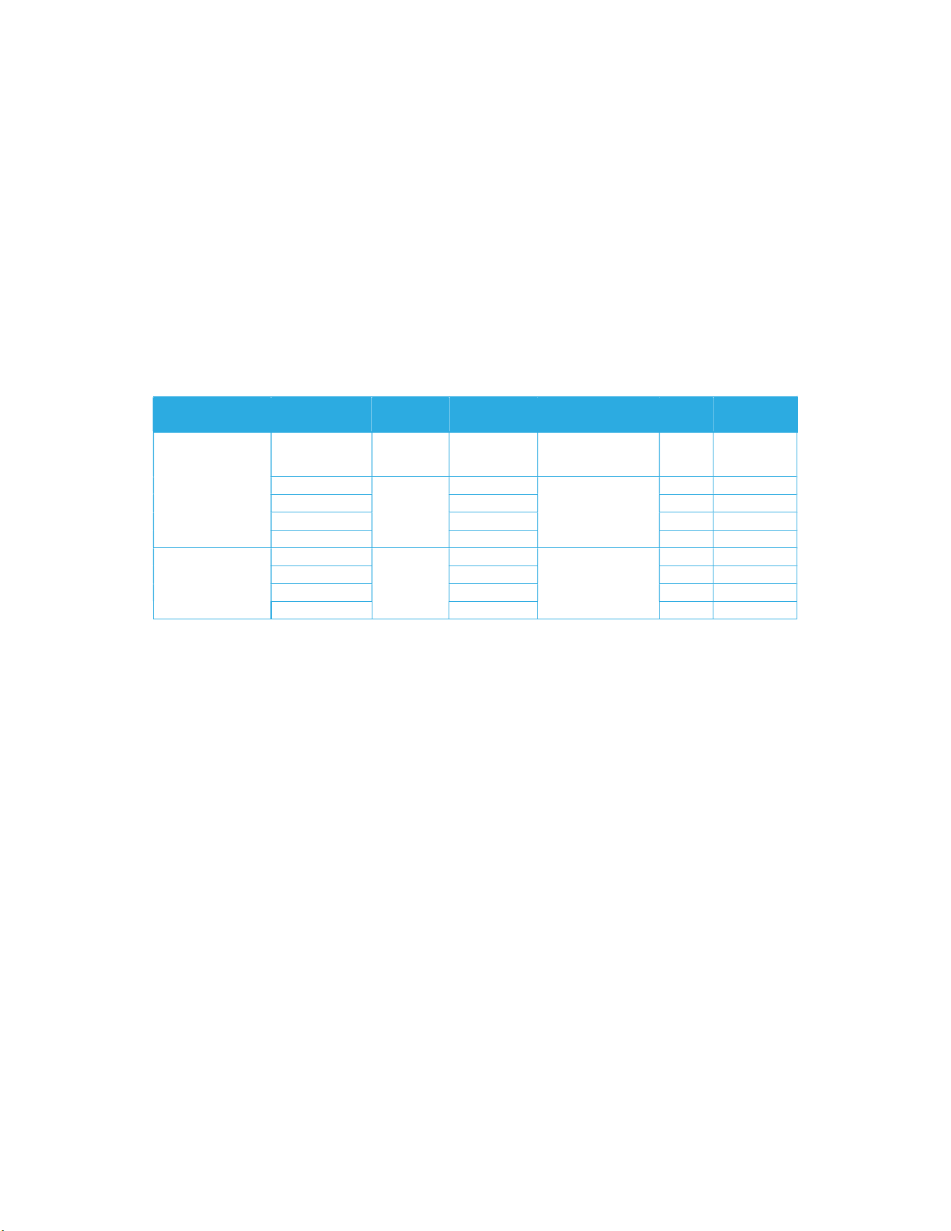
backhaul. Table 1 presents the currently available KONA Mega Gen3 Gateway models.
Table 1: KONA Mega Gen3 Gateway Models
Region
Gateway
Model No.
Channel
Plan
Radio
PCBA
Filter(s)
LoRa
Ant
Cellular
Backhaul
North
America
T0009532 Custom T0009347
T0009450
Rx: 902-919.2 MHz
Tx: 923-928 MHz
2 Yes
T0009627
US915
T0009378
T0004144
Rx: 902-915 MHz
Tx: 923-928 MHz
1 No
T0009626 T0009347 1 Yes
T0009519 T0009378 2 No
T0009520 T0009347 2 Yes
Europe
T0009630
EU868
T0009379
T0007842
863-870 MHz
1 No
T0009629 T0009348 1 Yes
T0009523 T0009379 2 No
T0009524 T0009348 2 Yes
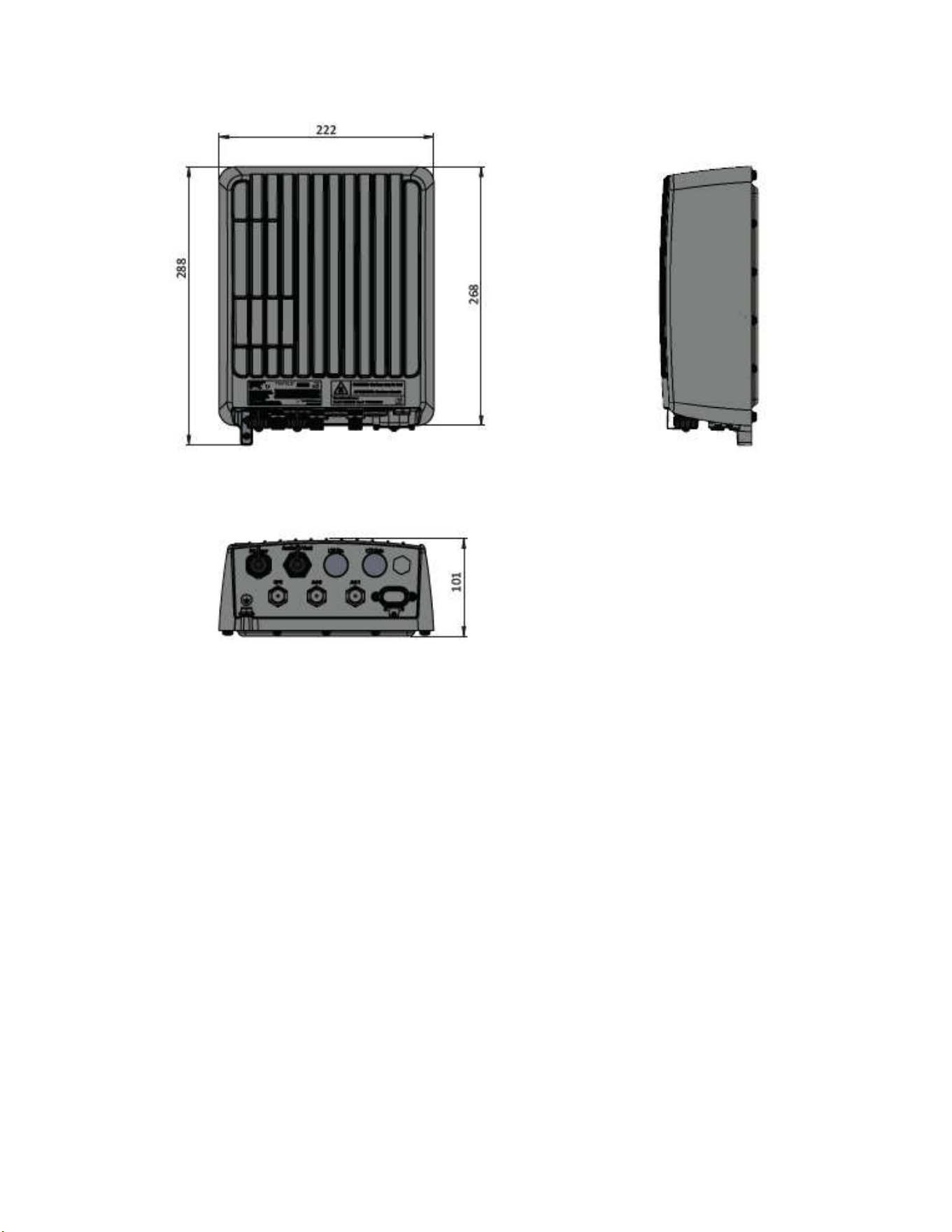
Figure 1 illustrates the common Gateway external form-factor. The differences between the
options are limited to the bulkhead field.
KONA Mega Gen3 Gateway User Guide T0009468_UG Version 1.2
TEKTELIC Communications Inc. Page 7 of 20
Figure 1: KONA Mega Gen3 Gateway Common Dimensions
KONA Mega Gen3 Gateway User Guide T0009468_UG Version 1.2
TEKTELIC Communications Inc. Page 8 of 20
1.2 Bulkhead Layout
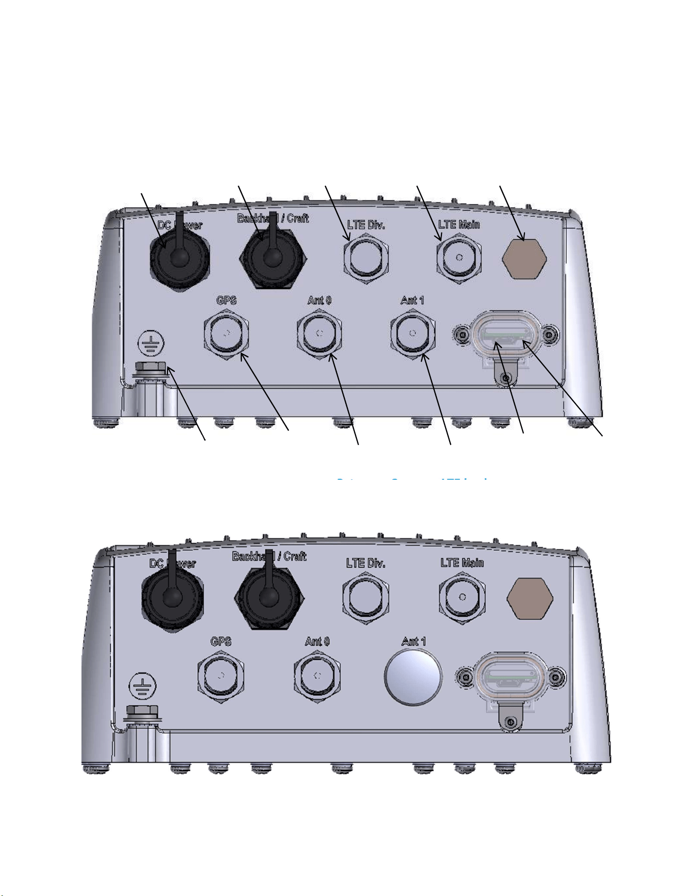
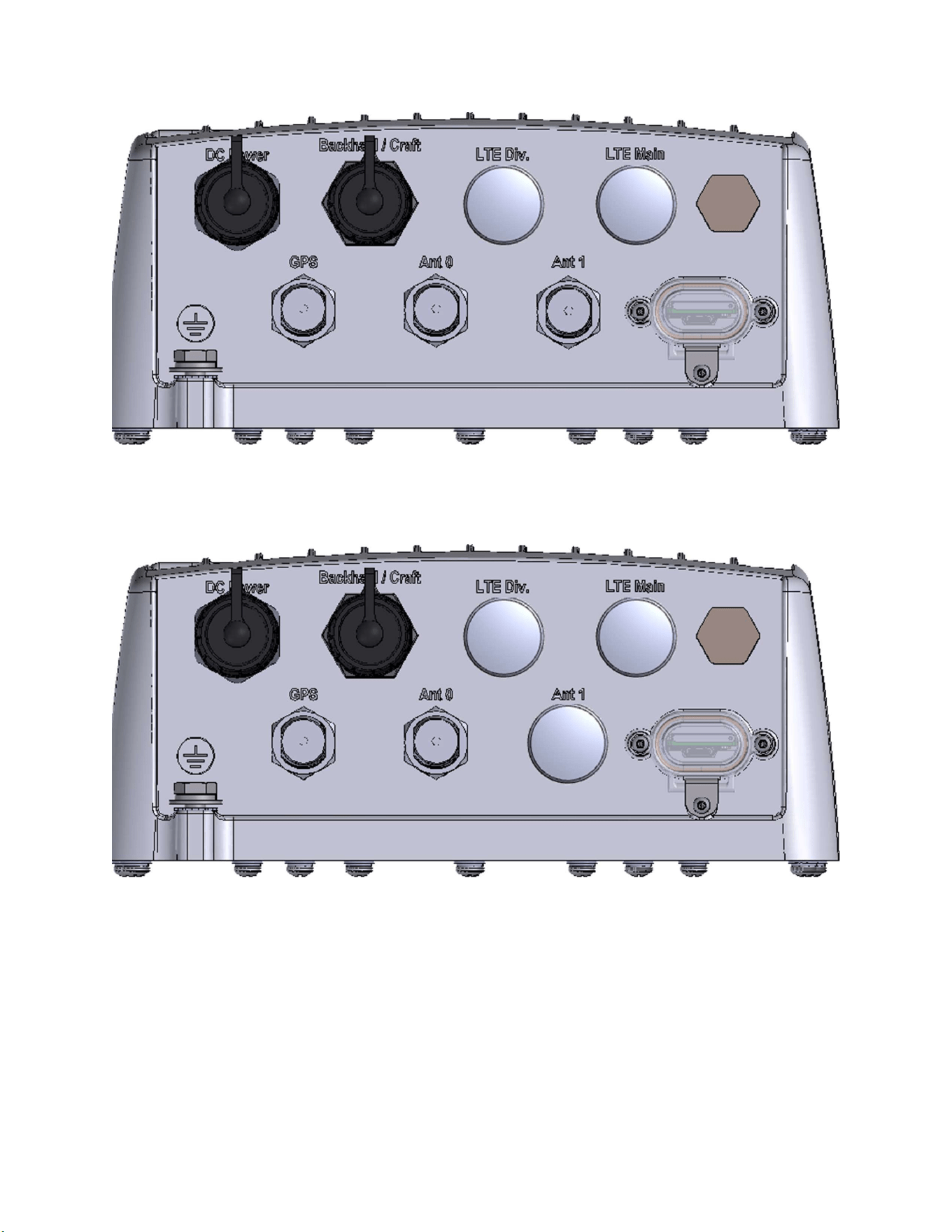
The KONA Mega Gen3 Gateway bulkhead component fields are detailed in the following figures.
Figure 2: KONA Mega Gen3 Gateway, 2x LoRa, LTE backhaul
Figure 3: KONA Mega Gen3 Gateway, 1x LoRa, LTE backhaul
Enclosure
Vent
Modem
Tx/Rx
Modem Rx
Copper
Ethernet
DC Power
Protective
Earth Ground
GPS Antenna
LoRa Ant0
LoRa Ant1
SIM/UART
access
LED
KONA Mega Gen3 Gateway User Guide T0009468_UG Version 1.2
TEKTELIC Communications Inc. Page 9 of 20
Figure 4: KONA Mega Gen3 Gateway, 2x LoRa, Ethernet backhaul only
Figure 5: KONA Mega Gen3 Gateway, 1x LoRa, Ethernet backhaul only
All KONA Gateway module interconnects are located on the bottom facing bulkhead. The RF
connectors are water proof while un-mated but all other connectors must be terminated with
mating connectors or covered with the supplied protective cap when not in use in order to be
water tight. Connector types and their mating connectors are listed in Table 2.
KONA Mega Gen3 Gateway User Guide T0009468_UG Version 1.2
TEKTELIC Communications Inc. Page 10 of 20
Table 2: KONA Mega Gen3 Gateway Interface Connector Types
Interface Connector Type
Mating Connector
LoRa Antenna N-Type female Industry standard N-Type male
Cellular Antenna N-Type female Industry standard N-Type male
GPS Antenna N-Type female Industry standard N-Type male
Copper Ethernet
(CPC connector)
Circular plastic threaded,
RJ-45
Shenzhen Chogori Technology Co., Ltd. Approved
mating connector (p/n 33000111-02 or equivalent)
DC Power Input
(CPC connector)
Circular plastic threaded, 2
contact, DC power
Shenzhen Chogori Technology Co., Ltd. Approved
mating connector (p/n 23002211-02 or equivalent)
Earth Ground 1/4 - 20 UNC double hole Industry standard 2-hole lug, 1/4 x 0.75” spacing

KONA Mega Gen3 Gateway User Guide T0009468_UG Version 1.2
TEKTELIC Communications Inc. Page 11 of 20
1.3 Specifications
The KONA Mega Gen3 Gateway specifications are listed in Table 3.
Table 3: KONA Mega Gen3 Gateway Specifications
Attribute
Specification
Dimensions
222
mm (8.7”) wide x 101mm (4.0”) deep x 287
mm (11.3”) tall
Weight
5.1 kg (11.3 lbs)
Operating Temperature
-
40°C to 60°C (
-
40°F to 140°F) at sea level Including solar loading.
Relative Humidity
10% to 100%
Operating Altitude
-
60 m to 4,000 m (
-
197 ft to 13,123 ft)
Power Input, Direct DC
48 VDC nominal, 37 to 57 VDC operating range (after 42 V maximum start
-
up threshold).
Positive or negative ground referenced feed. SELV & LPS source required.
Maximum 10A input overcurrent protection.
Power Input, PoE
IEEE 802.3 at over all four pairs (Mode A + Mode B) required
Power Consumption
35 W maximum
Weather Tightness
UL Type 6 (IP
-
67)
Regulatory Compliance
1
FCC, ISED, CE, CE (RED)
Surge Protection
All interfaces are protected to primary levels except for the 3G/4G modem
antenna port which supports local antenna mounting only or requires an
external surge suppressor.
1.4 Exposed Services
The following services are exposed in factory default state:
SSH (TCP port 22) – Provides secure command-line access to the equipment.
SNMPv3 (UDP port 161) – Secure management and monitoring with encryption and
authentication.
mDNS (UDP port 5353) – Enables local service discovery, allowing the use of user-friendly
domain names when addressing the equipment, limited to the local network scope.
ICMP (Ping) – Basic connectivity and availability check.
HTTPS (TCP port 443) – Provides secure access to the web management interface using TLS
encryption.
1
In Progress

KONA Mega Gen3 Gateway User Guide T0009468_UG Version 1.2
TEKTELIC Communications Inc. Page 12 of 20
2 Installation
2.1 Safety Precautions
Installation, operation, and maintenance of the KONA Mega Gen3 Gateway must only be
performed by a professionally trained service technician who is aware of all hazards involved.
The KONA Mega Gen3 Gateway must be installed in a restricted access location (such that
touching of the Gateway by non-service persons is not likely).
The KONA Mega Gen3 Gateway may become hot to the touch during normal operation at
elevated ambient temperatures. The surface temperature of the Gateway may reach 90°C.
The KONA Mega Gen3 Gateway has no internal field serviceable parts. The Gateway module
must only be opened by an approved TEKTELIC service center.
All installation practices must be in accordance with the local and national electrical codes.
Do not work on the system during periods of lightning activity.
The KONA Mega Gen3 Gateway is considered permanently connected equipment. The
Protective Earth Ground connection (that is, the two-hole lug to chassis ground) is always
required.
Ensure the KONA Mega Gen3 Gateway Protective Earth Ground connection is properly
terminated prior to the connection of any other interfaces.
The KONA Mega Gen3 Gateway contains primary lightning surge suppression on the Direct
DC power port, the Copper Ethernet port, the GPS antenna port and the LoRa RF antenna
ports. The primary lightning protectors have the ability to bridge the interface isolation
boundary during over-voltages. Ensure that the Protective Earth Ground connection is always
in place.
Ensure that the KONA Mega Gen3 Gateway, its antennas and supporting structures are
properly secured to eliminate any physical hazard to people or property. The Gateway must
be securely mounted according to the mounting instructions prior to any cable connection
and operation.
The KONA Mega Gen3 Gateway does not contain a power supply disconnection device; a
readily accessible disconnection device must be incorporated external to the KONA Mega
Gen3 Gateway.
The direct DC powered KONA Mega Gen3 Gateway shall be supplied through an input
overcurrent protection device rated not more than 10 A. The overcurrent protection must

KONA Mega Gen3 Gateway User Guide T0009468_UG Version 1.2
TEKTELIC Communications Inc. Page 13 of 20
have the appropriate current interrupt capacity for the power source and must be
incorporated into the non-earthed conductor(s) of the KONA Mega Gen3 Gateway DC supply.
For the direct DC power feed option, the DC positive pin must be at positive potential relative
to the DC negative pin. If the polarity is reversed, the unit will not sustain damage but will not
operate until the connection polarity is corrected.
Although the KONA Mega Gen3 Gateway can be powered through either a direct DC input or
through power over Ethernet (PoE), simultaneous application of power to both inputs may
result in unexpected operation and shall be avoided.
The KONA Mega Gen3 Gateway power source must meet SELV requirements.
2.2 Unpacking and Inspection
The following should be considered during the unpacking of a new KONA Mega Gen3 Gateway.
1. Inspect the shipping carton and report any significant damage to TEKTELIC.
2. Unpacking should be conducted in a clean and dry location when possible.
3. Do not discard the shipping box or foam inserts as they will be required if a unit is returned
for repair or re-configuration.
2.3 Required Equipment for Installation
The following tools are required to install the KONA Mega Gen3 Gateway module:
1. A 6 point metric socket set and torque wrench drive.
2. Anti-oxidant compound (NO-OX-ID, Penetrox, Noalox, Ox-Gard or equivalent).
3. A small wire brush.
4. A clean cloth.
5. Weatherproofing tape kit for the RF connectors (Scotch Wireless Weatherproofing Kit,
WK-101 recommended).
6. Appropriately sized pipe clamps for pole mounting or appropriate screws or bolts (four
sized M8) with any required anchors according to the wall construction for wall mounting.
2.4 KONA Mega Gen3 Gateway Mounting
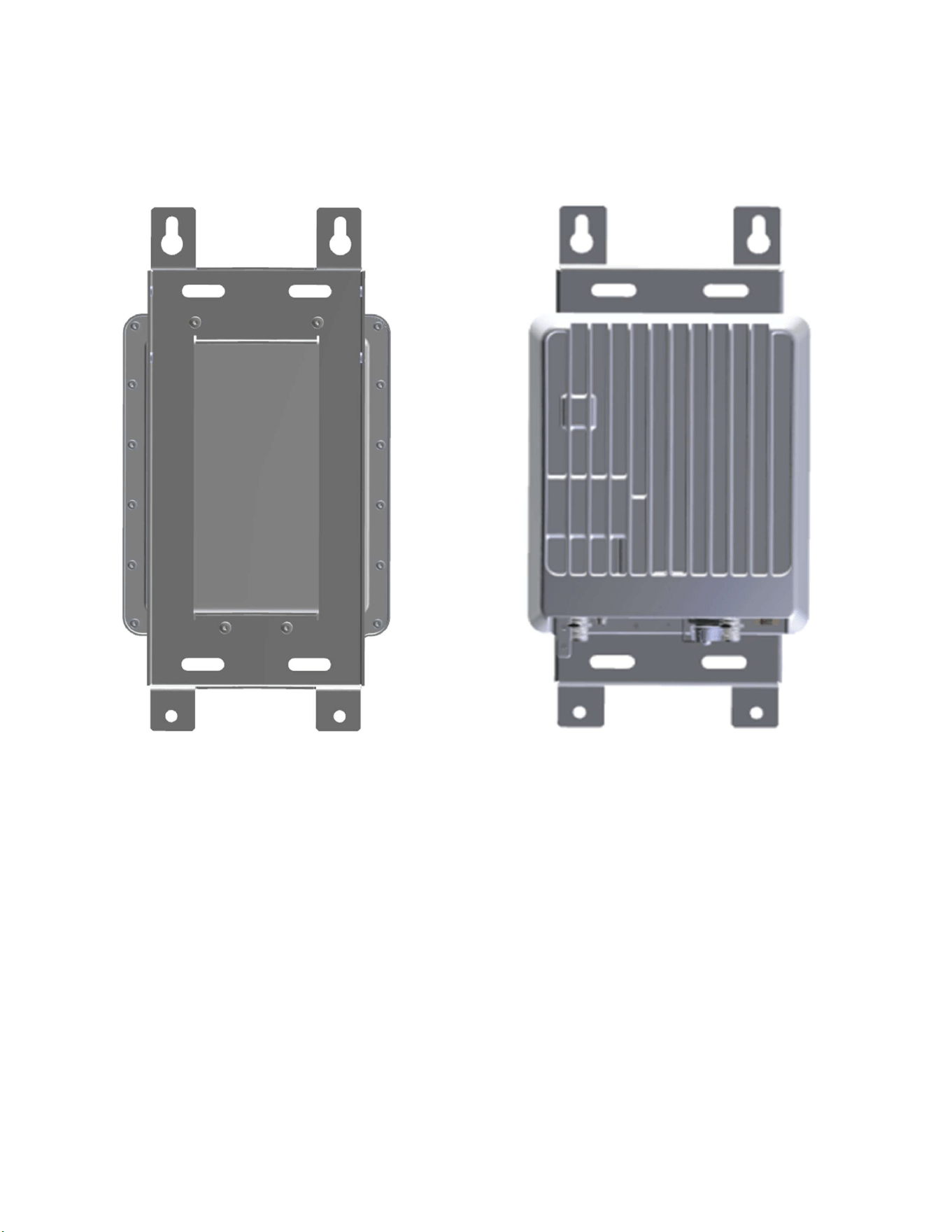
KONA Mega Gen3 Gateway is designed to be mounted to a vertical pole or wall using a mounting
bracket. The mounting bracket is a single part that bolts to the back surface of the Gateway using
supplied hardware (four M6x1.0 - 14 mm bolts with flat and star lock washers) as illustrated in
Figure 6. The Gateway module must be oriented with the connector bulkhead facing down,
towards earth.
KONA Mega Gen3 Gateway User Guide T0009468_UG Version 1.2
TEKTELIC Communications Inc. Page 14 of 20
Ensure that the structure to which the Gateway is being mounted is secure and able to support
a dead load of at least 136 kg (300 lbs). The area below must be free of any obstructions to cable
ingress.
Figure 6: KONA Module with Mounting Bracket
The KONA Mega Gen3 Gateway wall mounting procedure is as follows:
1. Bolt the wall mounting bracket to the Gateway module using the supplied bolts and
washers.
2. Install 2 site supplied M8 bolts into the wall at 139.7 mm (5.5”) center spacing, leaving
the bold heads protruding with a 2mm gap from the wall surface.
3. Hang the KONA Mega Gen3 Gateway with bracket from the two bolts by inserting the
keyhole slots at the top of the bracket onto the 2 bolts and tightening the bolts.
4. Insert and tighten two additional site supplied M8 bolts through the holes at the bottom
of the bracket.
The KONA Mega Gen3 Gateway pole mounting procedure is as follows:
KONA Mega Gen3 Gateway User Guide T0009468_UG Version 1.2
TEKTELIC Communications Inc. Page 15 of 20
1. Bolt the wall mounting bracket to the Gateway module using the supplied bolts and
washers.
2. While temporarily supporting the Gateway with bracket, install the two site supplied pipe
clamps, one through each of the upper and lower slotted clamp mounting points.
2.5 Ground Cable Installation
The KONA Mega Gen3 Gateway is considered Permanently Connected Equipment and requires a
permanently connected Protective Earth Ground (PEG) conductor. The Protective Earth Ground
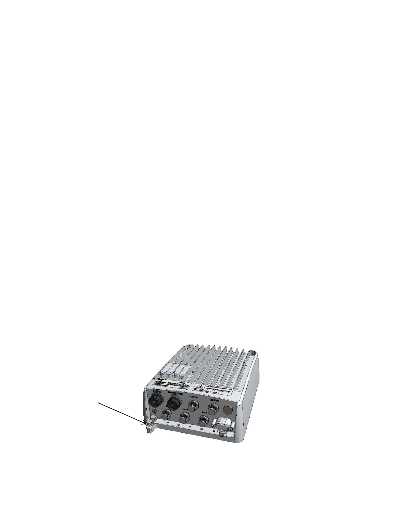
connection is made through a 1/4 x 0.75” on center double hole lug to the ground termination
point illustrated in Figure 7. The ground cable gauge shall be #10 AWG minimum.
The KONA Mega Gen3 Gateway grounding system shall follow local and national electrical codes.
The Protective Earth Ground conductor terminated at the double hole lug point is mandatory and
must be the first connection made to the KONA Mega Gen3 Gateway during installation. Proper
routing and termination of this cable is key to robust lightning withstand performance; in high
susceptibility installations, every effort shall be made to minimize connection inductance and
ground bed resistance.
The ground cable installation steps are as follows:
1. Lightly abrade the surface of the casting ground area with a fine wire brush to remove the
oxide layer.
2. Use a clean cloth to remove any debris from this surface.
3. Immediately coat the contact surface with a thin layer of anti-oxidant compound.
4. Install the ground cable through its 2-hole lug onto the chassis ground point using the two
supplied 1/4 - 20 x 1/2” bolts with flat and star lock washers, torqued to 10.4 Nm (92
in·lbs).
Figure 7: Chassis Ground Connection
Earth Ground
Connection
KONA Mega Gen3 Gateway User Guide T0009468_UG Version 1.2
TEKTELIC Communications Inc. Page 16 of 20
2.6 Direct DC Power Cable Installation
Depending on the model, the KONA Mega Gen3 Gateway direct DC feed may terminate at a
dedicated two pin circular plastic connector (CPC) or a two pin M12 circular metal connector. In
either case the direct DC power input is isolated from chassis (earth) with the exception of the
primary surge suppressors. One lead of the DC power feed is normally earth referenced external
to the KONA Mega Gen3 Gateway (usually at the power source by convention).
The DC power cable shall be rated for outdoor application and in accordance with local and
national electrical codes.
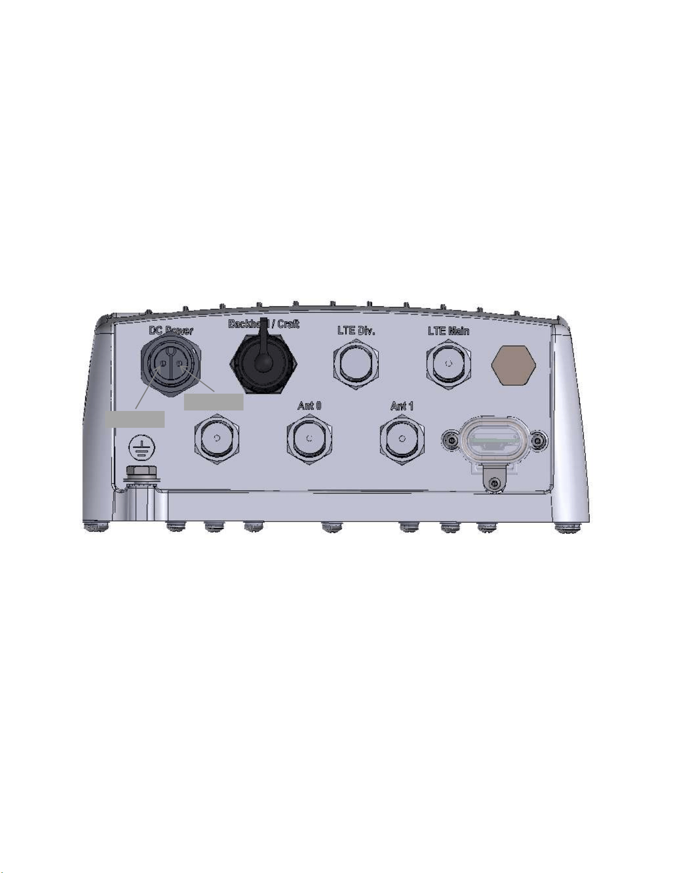
The CPC DC connector shall be as specified in Table 2 and shall follow the signal polarity
identified in Figure 8.
Figure 8: Direct DC Power Connection Polarity
2.7 RF Cable Installation
The Gateway installation will require connection to a GPS antenna, up to two LoRa RF antennas,
and optionally 3G/4G modem antennas. The RF cables attach to the N-Type connectors on the
bottom of the KONA Mega Gen3 Gateway. Torque the connectors to 1.7 to 2.3 Nm (15 to 20
in·lbs). The N-Type connector interface to a cable is not water proof and must be taped to be
used outdoors. TEKTELIC recommends taping with Scotch Wireless Weatherproofing Kit, WK-101.
Follow the taping procedures outlined by the supplier of this tape system.
DC Positive
DC Negative

KONA Mega Gen3 Gateway User Guide T0009468_UG Version 1.2
TEKTELIC Communications Inc. Page 17 of 20
The Gateway, by nature of its deployment, is expected to have a high level of lightning exposure.
All RF ports have primary levels of surge protection integrated in the Gateway module which
includes:
LoRa RF antenna ports
Cellular RF antenna ports
GPS RF antenna port
2.8 Copper Ethernet Cable Installation
The KONA Mega Gen3 Gateway Ethernet port may be used on a temporary basis for
commissioning and maintenance or may be permanently connected for backhaul. When the port
is not in use, the weatherproof protective cap must be installed. When the port is permanently
connector for backhaul, a proper water-tight mating connector specified in Table 2 must be used.
The Ethernet cable must have minimum 24 AWG conductors and shall be rated for outdoor
application according to local and national electrical codes.
The Ethernet port is equipped with primary surge protection.
2.9 Proposition 65 Statement
WARNING: This product can expose you to chemicals including lead, beryllium & nickel, which
are known to the State of California to cause cancer, birth defects or other reproductive harm.
For more information, go to www.P65Warnings.ca.gov.

KONA Mega Gen3 Gateway User Guide T0009468_UG Version 1.2
TEKTELIC Communications Inc. Page 18 of 20
3 Radio Compliance Statements
Federal Communications Commission
This device complies with Part 15 of the FCC Rules. Operation is subject to the following two conditions:
1. This device may not cause harmful interference, and
2. This device must accept any interference received, including interference that may cause undesired operation.
Changes or modifications not expressly approved by the party responsible for compliance could void the user’s authority to
operate the equipment
This equipment has been tested and found to comply with the limits for a Class B digital device, pursuant to Part 15 of the FCC
Rules. These limits are designed to provide reasonable protection against harmful interference in a residential installation.
This equipment generates uses and can radiate radio frequency energy and, if not installed and used in accordance with the
instructions, may cause harmful interference to radio communications. However, there is no guarantee that interference will
not occur in a particular installation. If this equipment does cause harmful interference to radio or television reception, which
can be determined by turning the equipment off and on, the user is encouraged to try to correct the interference by one of
the following measures:
• Reorient or relocate the receiving antenna.
• Increase the separation between the equipment and receiver.
• Connect the equipment into an outlet on a circuit different from that to which the receiver is connected.
• Consult the dealer or an experienced radio/TV technician for help.
To comply with FCC/IC RF exposure limits for general population / uncontrolled exposure, the antennas used for this
transmitter must be installed to provide a separation distance of at least 80 cm from all persons and must not be co-located
or operating in conjunction with any other antenna or transmitter.
KONA Mega Gen3 Gateway User Guide T0009468_UG Version 1.2
TEKTELIC Communications Inc. Page 19 of 20
Industry Canada
This Device complies with Industry Canada License-exempt RSS standard(s). Operation is subject to the following two
conditions:
1. This device may not cause interference, and
2. This device must accept any interference, including interference that may cause undesired operation of the device.
This radio transmitter (certification number) has been approved by Industry Canada to operate with the antenna types listed
below with the maximum permissible gain indicated. Antenna types not included in this list, having a gain greater than the
maximum gain indicated for that type, are strictly prohibited for use with this device.
The required antenna impedance is 50 ohms.
Only antenna with maximum gain of 8dBi can be used for the LoRa radios of this product if the cable insertion loss at 900 MHz
is 0.5dB or more for 1 carrier operation at 28.5 dBm. Antenna(s) shall be installed to location providing a separation distance
of at least 31.5 inches (80 cm) from any human body.
During product operation, always keep a separation distance of at least 31.5 inches (80 cm) from any connected antenna(s).
Before servicing the product, the antenna(s) or cables, turn off the transmission function or the unit power if you have to get
closer than the minimum separation distance.
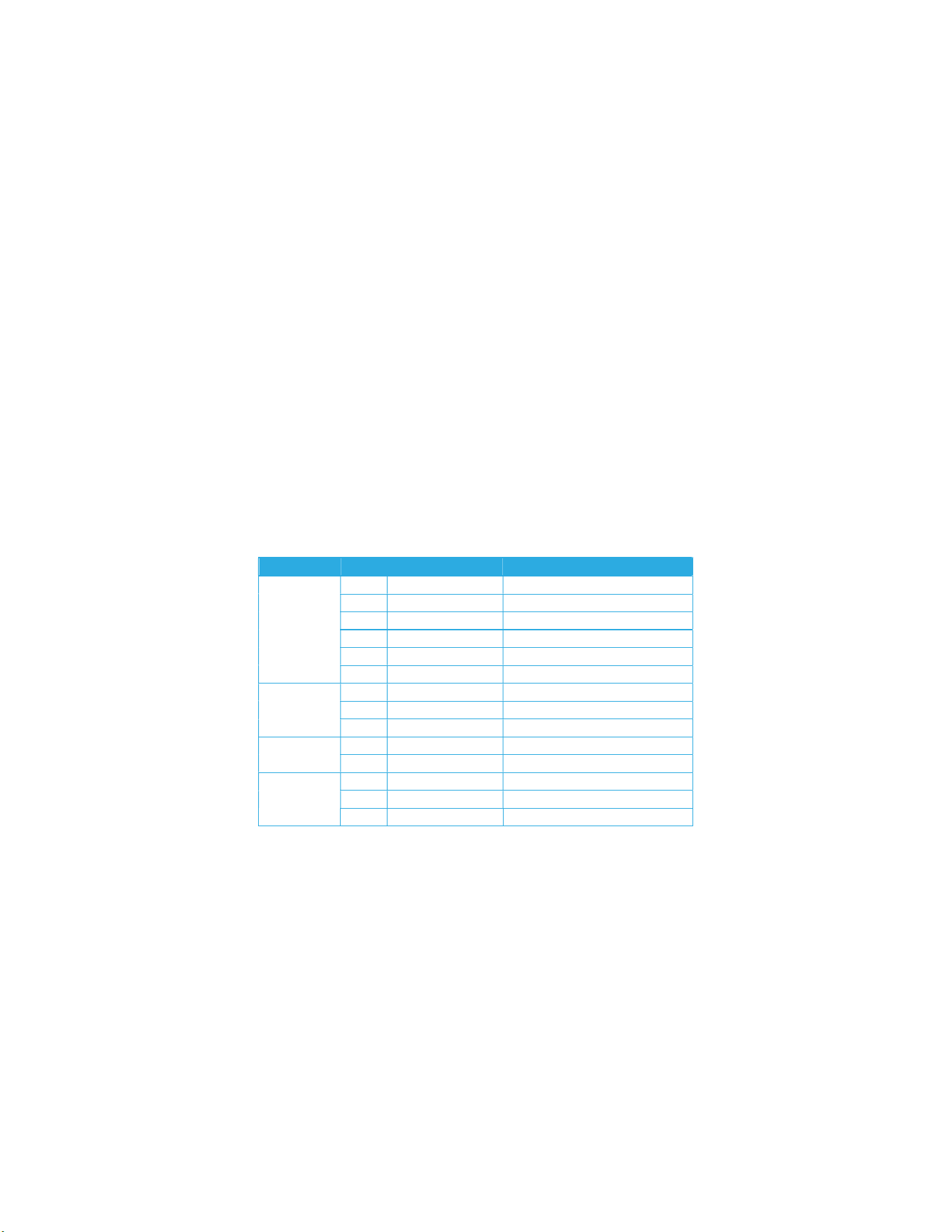
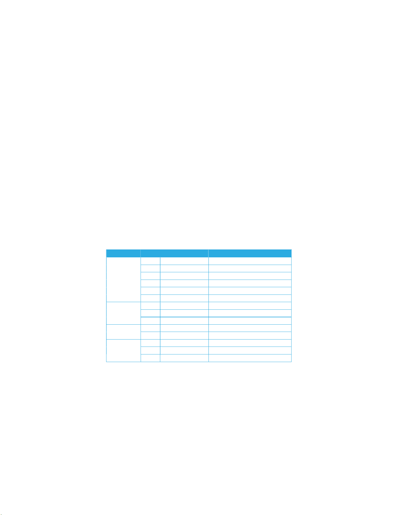
The 3G/4G modem antenna maximum allowed gain including cable loss shall be in accordance with the following table:
Technology Band Frequency (MHz) Maximum Antenna Gain (dBi)
LTE
2 1850–1910 3.0
4 1710–1755 6.0
5 824–849 3.0
13 777–787 6.0
17 704–716 6.0
25 1850–1915 3.0
UMTS
2 1850–1910 3.0
4 1710–1755 6.0
5 824–849 3.0
GSM
850 824–849 3.0
1900 1850–1910 3.0
CDMA
BC0 824–849 3.0
BC1 1850–1910 3.0
BC10 817–824 3.0
KONA Mega Gen3 Gateway User Guide T0009468_UG Version 1.2
TEKTELIC Communications Inc. Page 20 of 20
Industrie Canada
Cet appareil est conforme aux normes RSS d'Industrie Canada exemptées de licence. Son fonctionnement est soumis aux
deux conditions suivantes:
1. Cet appareil ne doit pas provoquer d'interférences et
2. Cet appareil doit accepter toute interférence, y compris les interférences pouvant entraîner un fonctionnement
indésirable de l'appareil.
Cet émetteur radio (numéro de certification) a été approuvé par Industrie Canada pour fonctionner avec les types d'antennes
énumérés ci-dessous avec le gain maximal autorisé indiqué. Les types d'antennes non inclus dans cette liste, ayant un gain
supérieur au gain maximal indiqué pour ce type, sont strictement interdits avec ce périphérique.
L'impédance d'antenne requise est de 50 ohms.
Seule une antenne avec un gain maximal de 8dBi peut être utilisée pour les radios LoRa de ce produit si la perte d'insertion de
câble à 900 MHz est de 0,5dB ou plus pour une opération de porteuse à 28,5 dBm. Une ou plusieurs antennes doivent être
installées à un emplacement situé à au moins 31,5 pouces (80 cm) de tout corps humain.
Pendant le fonctionnement du produit, conservez toujours une distance de séparation d'au moins 31,5 cm (80 cm) de toute
antenne connectée. Avant de réparer le produit, la ou les antennes ou les câbles, désactivez la fonction de transmission ou la
puissance de l'unité si vous devez vous rapprocher de la distance de séparation minimale.
Le gain maximal admissible de l'antenne du modem 3G / 4G, y compris la perte de câble, doit être conforme au tableau
suivant:
Technology Band Frequency (MHz) Gain maximum d'antenne (dBi)
LTE
2 1850–1910 3.0
4 1710–1755 6.0
5 824–849 3.0
13 777–787 6.0
17 704–716 6.0
25 1850–1915 3.0
UMTS
2 1850–1910 3.0
4 1710–1755 6.0
5 824–849 3.0
GSM
850 824–849 3.0
1900 1850–1910 3.0
CDMA
BC0 824–849 3.0
BC1 1850–1910 3.0
BC10 817–824 3.0