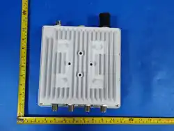

LoRaWAN Type III Outdoor Gateway
Quick Start Guide
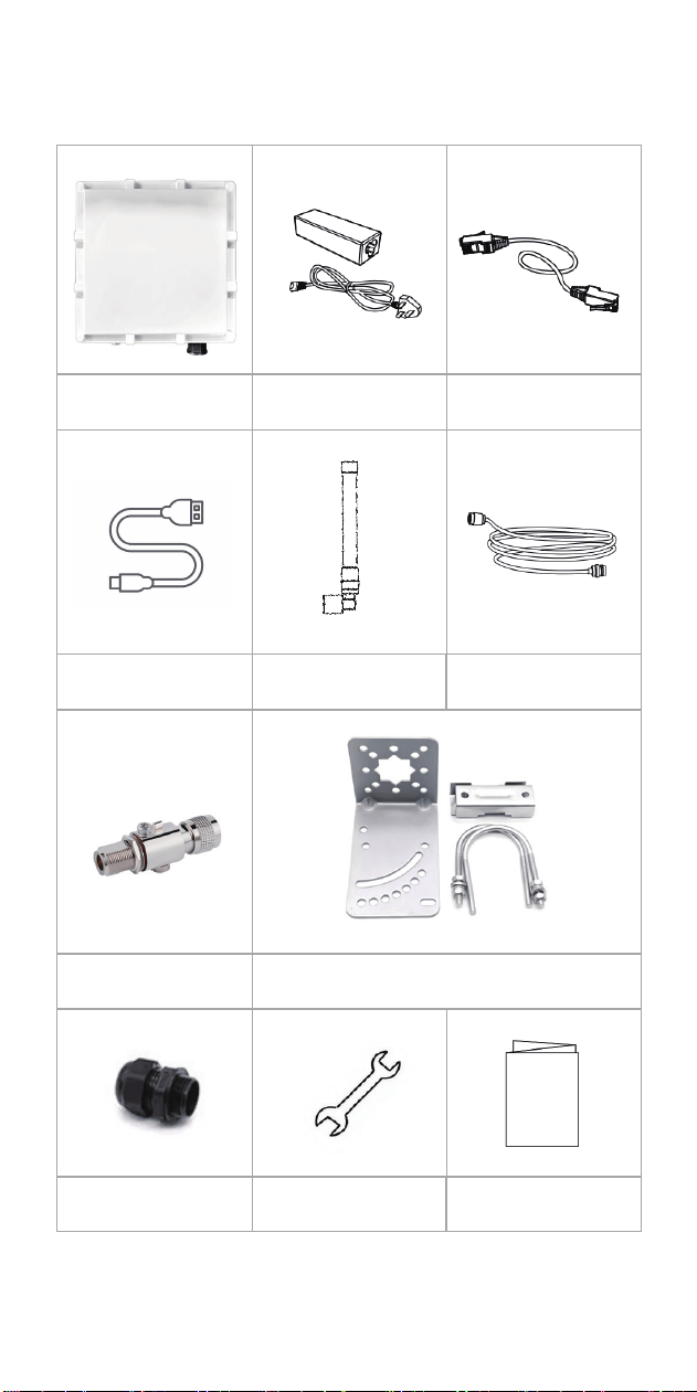
LoRaWAN Type III
Outdoor Gateway
POE and POE
Power Cord 1
Network Cable 1
Micro USB Cable 1
Fiberglass Antenna
(Half-duplex 4 / Full-duplex 5)
Antenna Extension Cable
(Half-duplex 1 / Full-duplex 2)
Lightning Protector 1 Right Angle Steel Plate Accessories & Screws 1
POE Connection Cable
External Connector Cap 1
Wrench 1
Certificate of Conformity and
Quick Installation Manual
* If any of the above items are damaged, missing, or if you have other accessory
requirements, please contact your agent or sales representative promptly.
1
1. Packing List
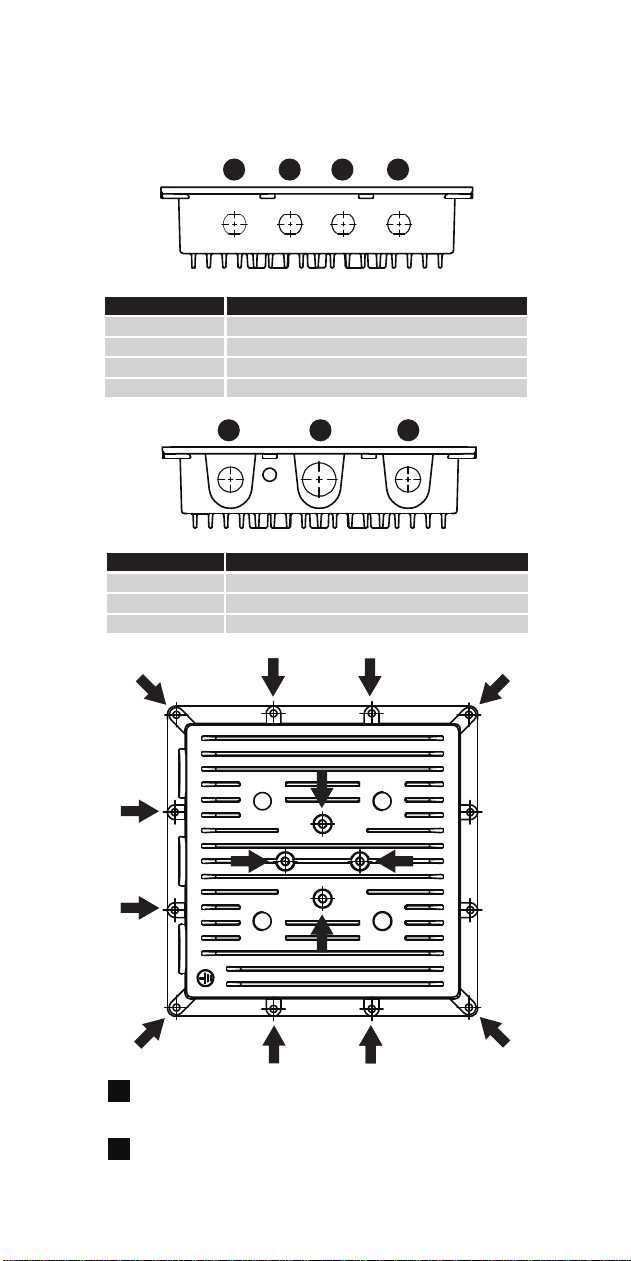
2. Interface Introduction
1 2 3
5 6 7
4
Interface Number
1
2
LORA RX Antenna (for full-duplex use)
LORA TRX Antenna
3
4
Interface Definition
Interface Number
5 4G DRX Antenna
6 SIM Card Installation Interface & SIM Card Slot
7 POE Network Cable Port (Data + Power)
Interface Definition
AA
B
A
A
AA A
AA A
A
A
A
B
B
B
The bottom stud holes are for connecting the top housing to
the device body. A total of 12 screws. After removing them,
the top cover can be opened for device maintenance.
Structural mounting screw holes. A total of 4 screws for easy
fixing of the device to other installation locations.
A
B
2
4G MAIN Antenna
WIFI Antenna
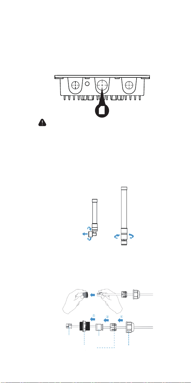
3. Accessory Installation
Step 1:
Twist open the SIM card plug slot. Insert the SIM card into the SIM card
slot according to the indicated position. Ensure the metal contacts of the
card face downwards. To remove the card, press and slide the clip on
the right side of the SIM card slot.
Step 2 :
Install external antennas
Install the corresponding antennas according to the hardware diagram.
When installing the 4G antenna and the WIFI antenna, screw the antenna
into the interface and try to point it upwards.
When installing the LORA antenna: if using a long antenna, an N-type
male to N-type male feeder cable is required for connection.
Refer to the installation diagram (Long LORA antenna requires a patch
cable for connection).
Step 3 :
Connect the ethernet cable cable and power cord to the corresponding
ports on the POE power supply according to the port labels.
When connecting the ethernet cable, pass it through the waterproof
gland, connect it to the device's Ethernet port, then screw the gland
onto the device and tighten it.
The gateway does not support hot-swapping. Please power off the
device before inserting or removing the SIM card.
3
Ethernet cable
Bolt
Nut
Rubber gasket
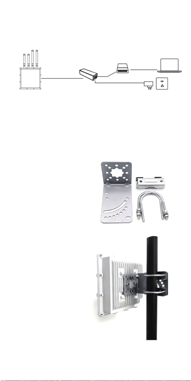
4. POE Connection Diagram
5. Right Angle Steel Plate Mounting Diagram
LoRaWAN Type III
Outdoor Gateway
Installation Diagram
4
Ethernet cable
(data and power)
PoE power supply
Switch
Power cord
Power outlet
Ethernet cable
(data)
Ethernet cable
(data)
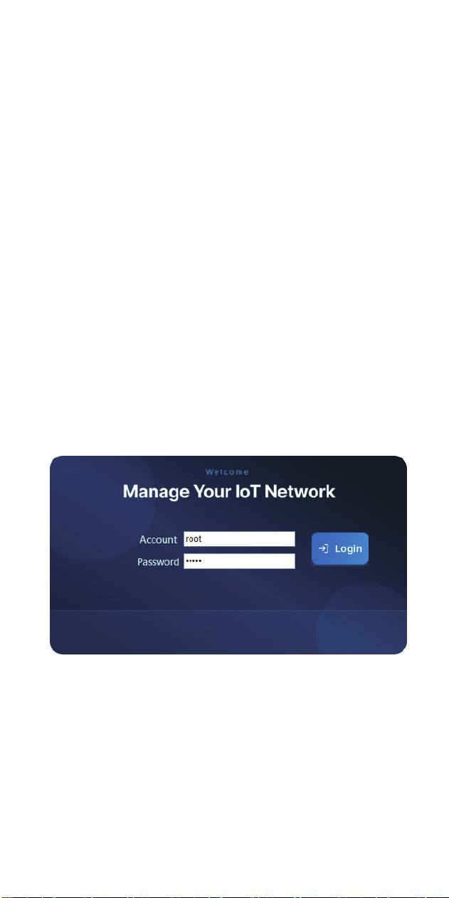
6. Accessing the Gateway Configuration Page
6.1. Connect to the gateway device using USB
Ensure the gateway device is operating normally.
At the bottom of the SIM card holder, there is a reserved Micro USB port. Use the
provided Micro USB cable to connect one end to the gateway device and the other
end to a computer. Enter the default gateway address 192.168.0.100:8088 in your
computer's web browser to access the web configuration page login interface.
6.2. Connect to the gateway device using an Ethernet cable
Connect the POE & network cable correctly as shown in sections 3 and 4. Log in to
the device via ADB or use IPCONFIG to obtain the gateway device's IP address.
Append the port number ”:8088 “ to the IP address to access the gateway's web
configuration page login interface.
6.3. Access the login page
After correctly connecting to the gateway device, use the corresponding IP address
to access the gateway web page via a computer browser. Example for USB access:
“http://192.168.0.100:8088/default/login.html”
5
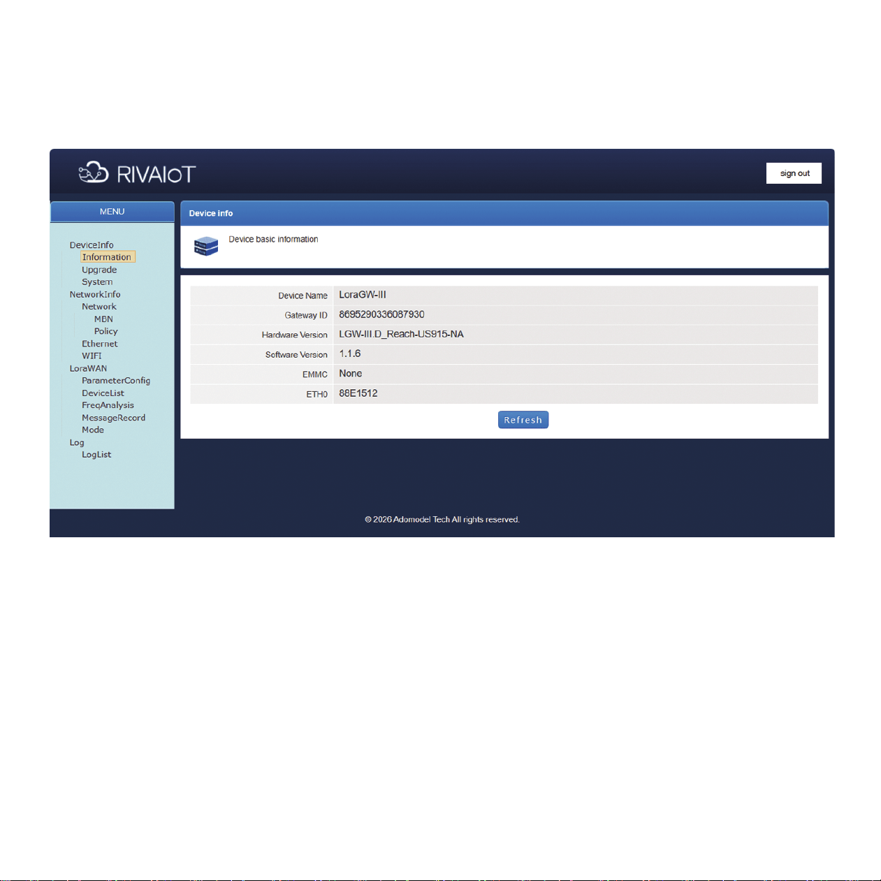
6.4. Log in to the gateway using the default credentials
The default username is: root
The default password is: admin
6

FCC Caution.
This device complies with part 15 of the FCC Rules. Operation is subject to the following two
conditions:
(1) This device may not cause harmful interference, and
(2) this device must accept any interference received, including interference that may cause
undesired operation.
Any Changes or modifications not expressly approved by the party responsible for compliance
could void the user's authority to operate the equipment.
Note: This equipment has been tested and found to comply with the limits for a Class B digital
device, pursuant to part 15 of the FCC Rules. These limits are designed to provide reasonable
protection against harmful interference in a residential installation. This equipment generates
uses and can radiate radio frequency energy and, if not installed and used in accordance with the
instructions, may cause harmful interference to radio communications. However, there is no
guarantee that interference will not occur in a particular installation. If this equipment does
cause harmful interference to radio or television reception, which can be determined by turning
the equipment off and on, the user is encouraged to try to correct the interference by one or
more of the following measures:
-Reorient or relocate the receiving antenna.
-Increase the separation between the equipment and receiver.
-Connect the equipment into an outlet on a circuit different from that to which the receiver is
connected.
-Consult the dealer or an experienced radio/TV technician for help.
FCC Radiation Exposure Statement:
This equipment complies with FCC radiation exposure limits set forth for an uncontrolled
environment. This equipment should be installed and operated with minimum distance 20 cm
between the radiator & your body.

