D1 Gateway User Manual
Item
Parameter
Type
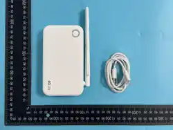
ETAP05-D1
Structure size
190mm(H)×190mm(V)×41mm(D)
Weight
360g
Appearance color
White
Operating voltage
DC 12V
Operating current
less than 300mA
Work Mode
2.4GHz
Work distance
Open space distance ≥ 30 meters
Data Interface
Standard network cable interface
Storage temperature
-30℃~70℃
Configure interface
USB2.0
Humidity
≤80%RH
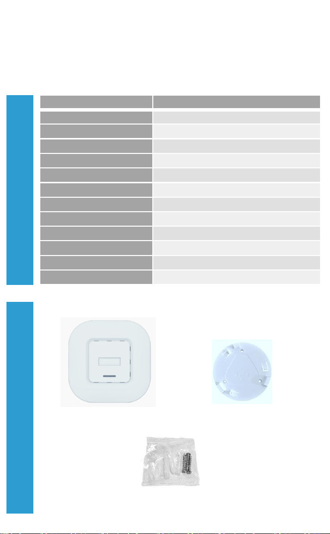
Gateway
Ceiling installation accessory
Set screw
Accessories in The Box
Product Parameters
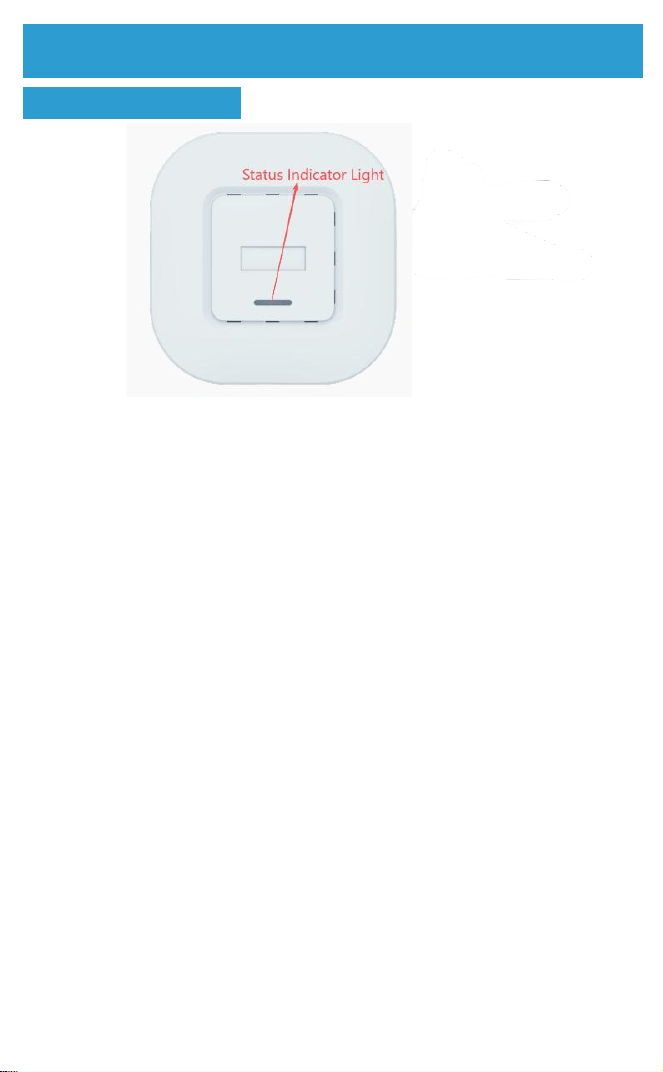
Front side introduction
Status indicator
LED_ B: Power indicator
LED_ R: Work indicator
Base Station Introduction
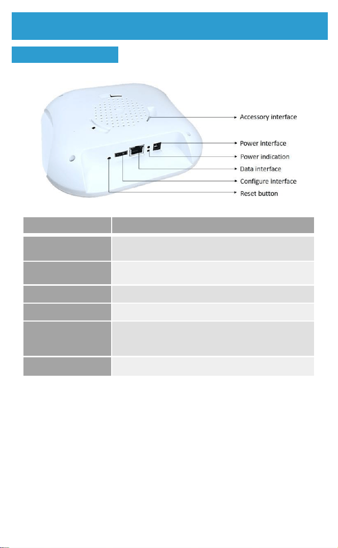
Back side introduction
Item
Parameter
Power interface
Use the standard DC 12V power supply
Power indication
Two lights are always on, indicating that the
power supply of the base station is normal
Data interface
Use UTP/STP of category 5 or above
Configure interface
USB2.0, USB flash disk configuration
Reset button
Press the reset button for about 8 seconds until the
yellow light stays on and then goes off, indicating
reset completion.
A c c e s s o r y
interface
Use with ceiling mounting accessories
Base Station Introduction
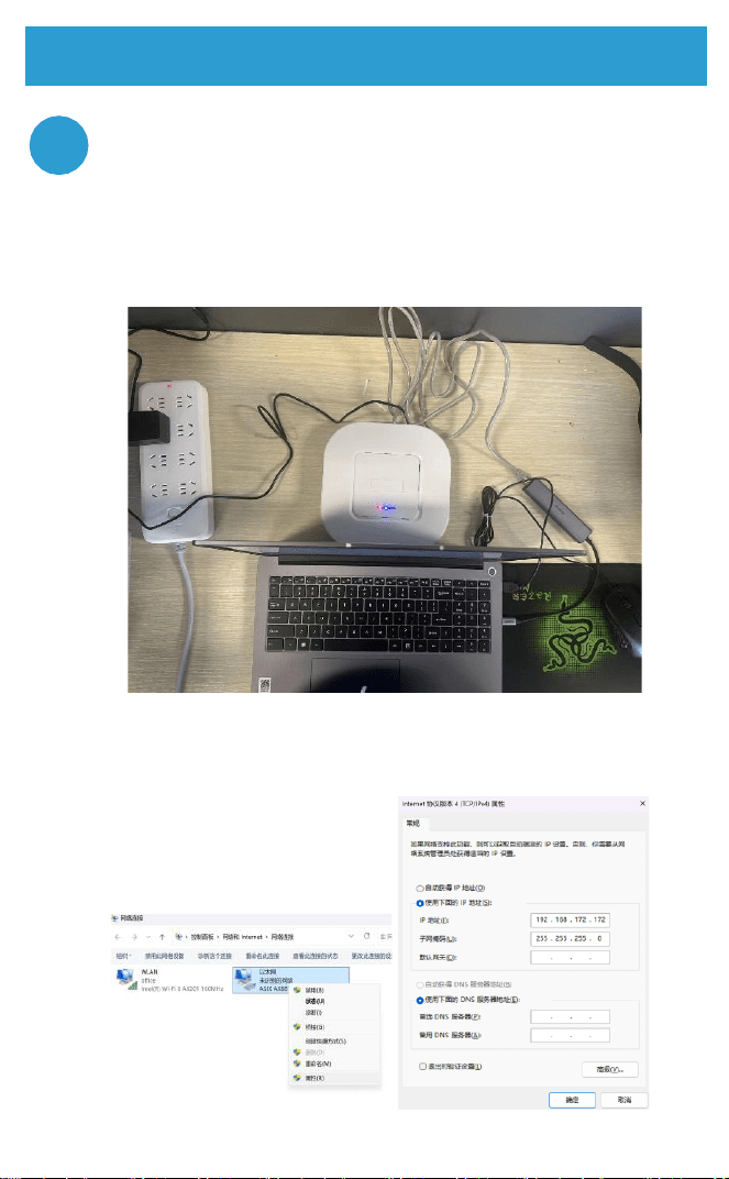
Hardware Environment Setup
1.1 Connect the base station to the power supply and wait for
about 20 seconds until the red light comes on, indicating that it
is ready to operate.
1.2 Plug an Ethernet cable into the base station to connect it to
the computer.
1.3 In the computer's network connections, change the Ethernet
IP address to 192.168.172.172 and the subnet mask to
255.255.255.0. After the modification is complete, power cycle
the base station.
Installation and configuration steps
1
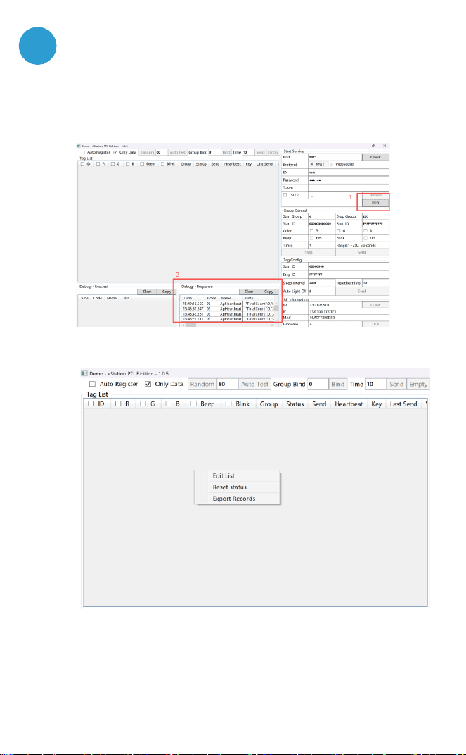
Open the eStation_PTL_Demo configuration tool and set the
relevant parameters.
2.1 Click "RUN". If data appears in the lower left corner, it means
the base station is successfully connected to the Demo tool. If no
data appears, press and hold the reset button on the base station
to reset it. (Remember to power cycle the base station.)
2.2 Control the light strip to turn on. Right-click in the gray area on
the left, click "Edit list" to add the light strip.
2.3 In the "Edit Light Strip List", enter a light strip number in each
row (ensure the input method is in English). You can add multiple
light strips. Finally, click "Save" to complete the addition of the light
strips.
2
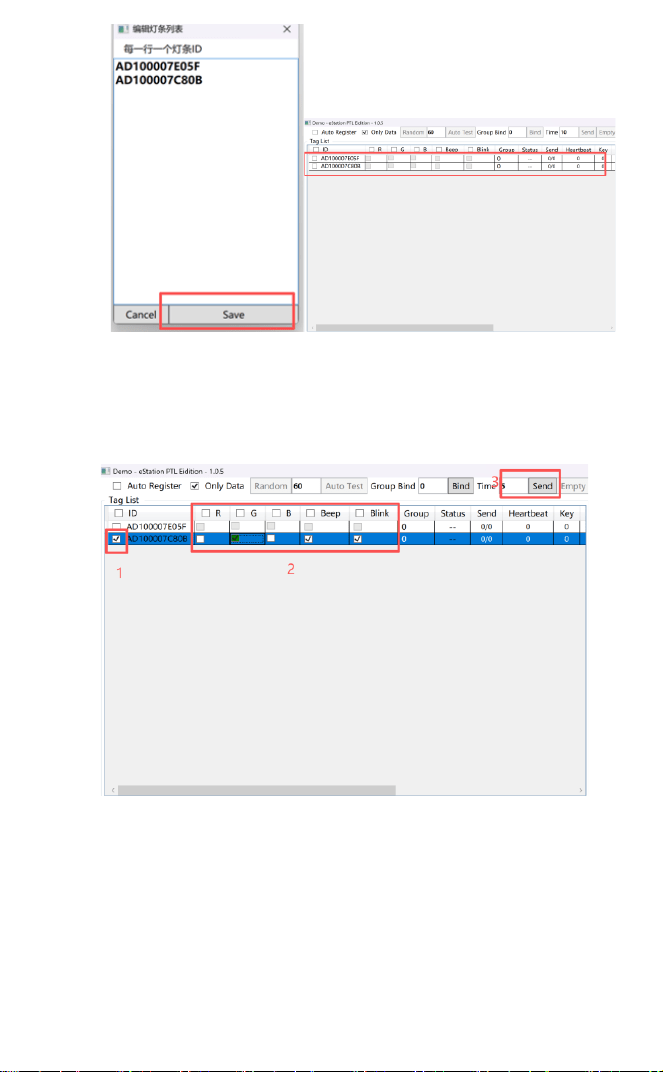
2.4 Select the light strip you want to control and choose its
parameters: "R" for red, "G" for green, "B" for blue, and you can
also mix and match these colors; "Beep" for the buzzer to sound;
"Blink" for the light to flash. "Time" represents the duration in
seconds. Finally, click "Send". The corresponding light strip will
respond accordingly.
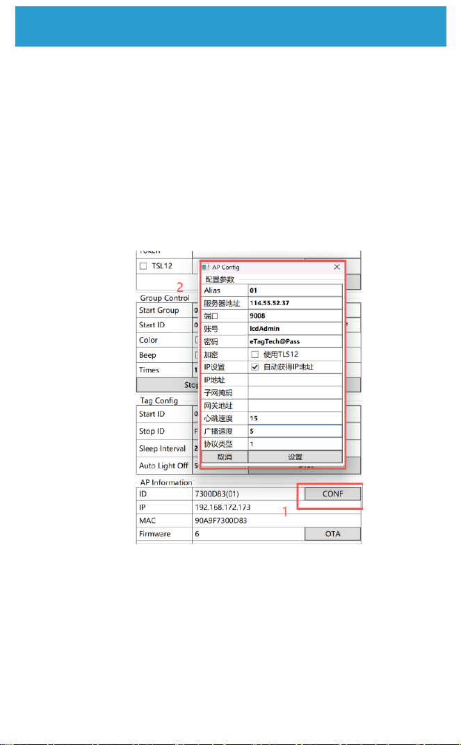
2.5 Configure the base station for public network deployment or local
deployment. Using Seekron public network deployment as an example,
click "CONF". In "AP Config", set the base station parameters: "Server
Address" is the IP address of the server the base station communicates
with; "Port" is the server's open port number; "Account, Password" are the
server's access credentials; "IP Address" is the base station's IP
(customizable but must be in the same network segment as the server IP); "
Subnet Mask" and
"Gateway Address" are customizable. Finally, click "Settings".
nstallation and setup steps
Power cycle the device and connect to use it.
3.1 After configuration is complete, disconnect the Ethernet
cable from the computer, connect it to the public network, and
power cycle the base station.
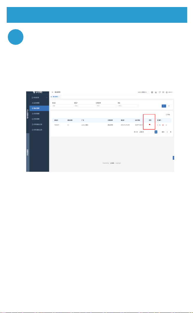
3.2 Open the server website to check if the base station is online. If
the "Status" shows a red heart, it means the base station has
successfully gone online.
Installation and setup steps
3

FCC STATEMENT
This device complies with Part 15 of the FCC Rules. Operation is subject to
the following two conditions: (1) This device may not cause harmful
interference, and (2) This device must accept any interference received,
including interference that may cause undesired operation.
This equipment has been tested and found to comply with the limits for a
Class B digital device, pursuant to part 15 of the FCC Rules. These limits
are designed to provide reasonable protection against harmful interference
in a residential installation. This equipment generates, uses and can radiate
radio frequency energy and, if not installed and used in accordance with the
instructions, may cause harmful interference to radio communications.
However, there is no guarantee that interference will not occur in a particular
installation. If this equipment does cause harmful interference to radio or
television reception, which can be determined by turning the equipment off
and on, the user is encouraged to try to correct the interference by one or
more of the following measures:
—Reorient or relocate the receiving antenna.
—Increase the separation between the equipment and receiver.
—Connect the equipment into an outlet on a circuit different from that to
which the receiver is connected.
—Consult the dealer or an experienced radio/ TV technician for help.
FCC Radiation Exposure Statement:
This equipment complies with FCC radiation exposure limits set forth for an
uncontrolled environment. In order to avoid the possibility of exceeding the
FCC radio frequency exposure limits, Human proximity to the antenna shall
not be less than 20cm(8 inches)during normal operation.
That changes or modifications not expressly approved by the party
responsible for compliance could void the user's authority to operate the
equipment.