
OWNER'S MANUAL
BODY-SOLID,Inc.
1900 S. Des Plaines Ave.
Forest Park, IL 60130 USA
Phone:(708)427-3555
Fax:(708)427-3556
www.bodysolid.com
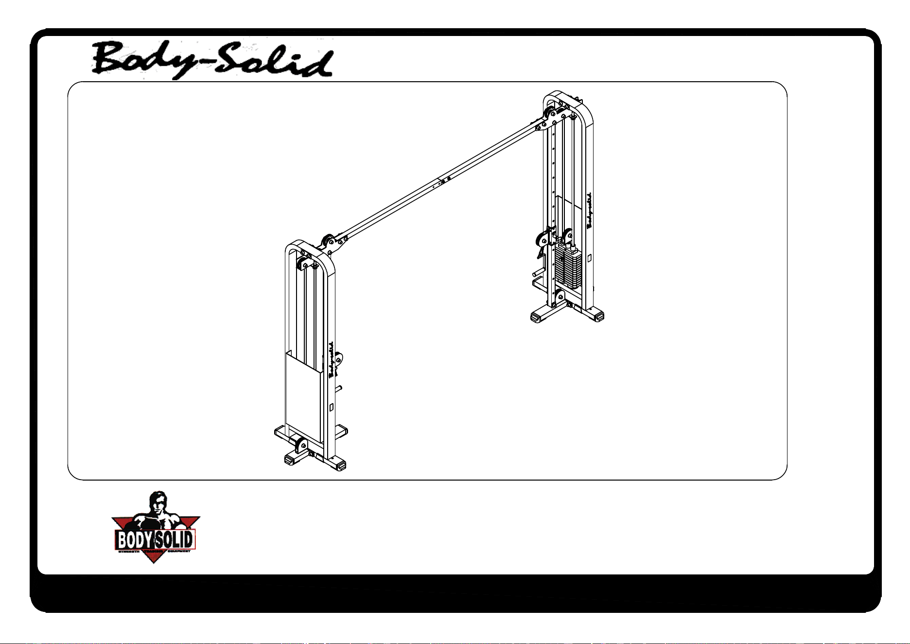
SCC-1200G.1
Warning, Safety & Maintenance
Be sure that all users carefully read and understand all
warning, safety and maintenance labels on the machine
before each use. Failure to do so may result in death or
serious injury.
It is imperative that you retain
your Owner’s
Manual
and be
sure all warning labels are legible and intact. Replacement
Owner’s Manuals and warning labels are available from your
local Body-Solid dealer.
If you have any questions about the operation, set up or
maintenance of this machine please call our customer service
department at 1 (800) 556-3113.
#DWRULE-4

Important Safety Instructions
Beforebeginninganyfitnessprogram,youshouldobtainacompletephysicalexaminationfromyourphysician.
Il est conseille de subir un examen medical complet avant d’entreprendre tout programme d’exercise.
Si vous avez des etourdissements ou des faiblesses, arretez les exercices immediatement.
Antes de comenzar cualquier programma de ejercicios, deberias tener un examen isico con su doctor.
When using exercise equipment, you
should always take basic precautions,
including the following:
m Readallinstructionsbeforeusingyour machine.
Theseinstructionsarewrittentoensureyoursafety
andtoprotecttheunit.
m Do not remove any safety labels from the
machine.
m Donotallowchildrenonorneartheequipment.
m Usetheequipmentonlyforitsintendedpurpose as
describedinthisguide.Donotuseaccessory
attachmentsthatarenotrecommendedbythe
manufacturer.Suchattachmentsmightcause
injuries.
m Wearproperexerciseclothingandshoesforyour
workout,nolooseclothing.
m Keephands,limbs,looseclothing,andlonghairwell
outofthewayofallmovingparts.
m Usecarewhengettingonorofftheunit.
m Donotoverexertyourselforworktoexhaustion.
m Ifyoufeelanypainorabnormalsymptoms,stop
yourworkoutimmediatelyandconsultyour
physician.
m Neveroperateunitwhenithasbeendroppedor
damaged.Returntheequipmenttoaservice center
forexaminationandrepair.
m Neverdroporinsertobjectsintoanyopeningin the
equipment.
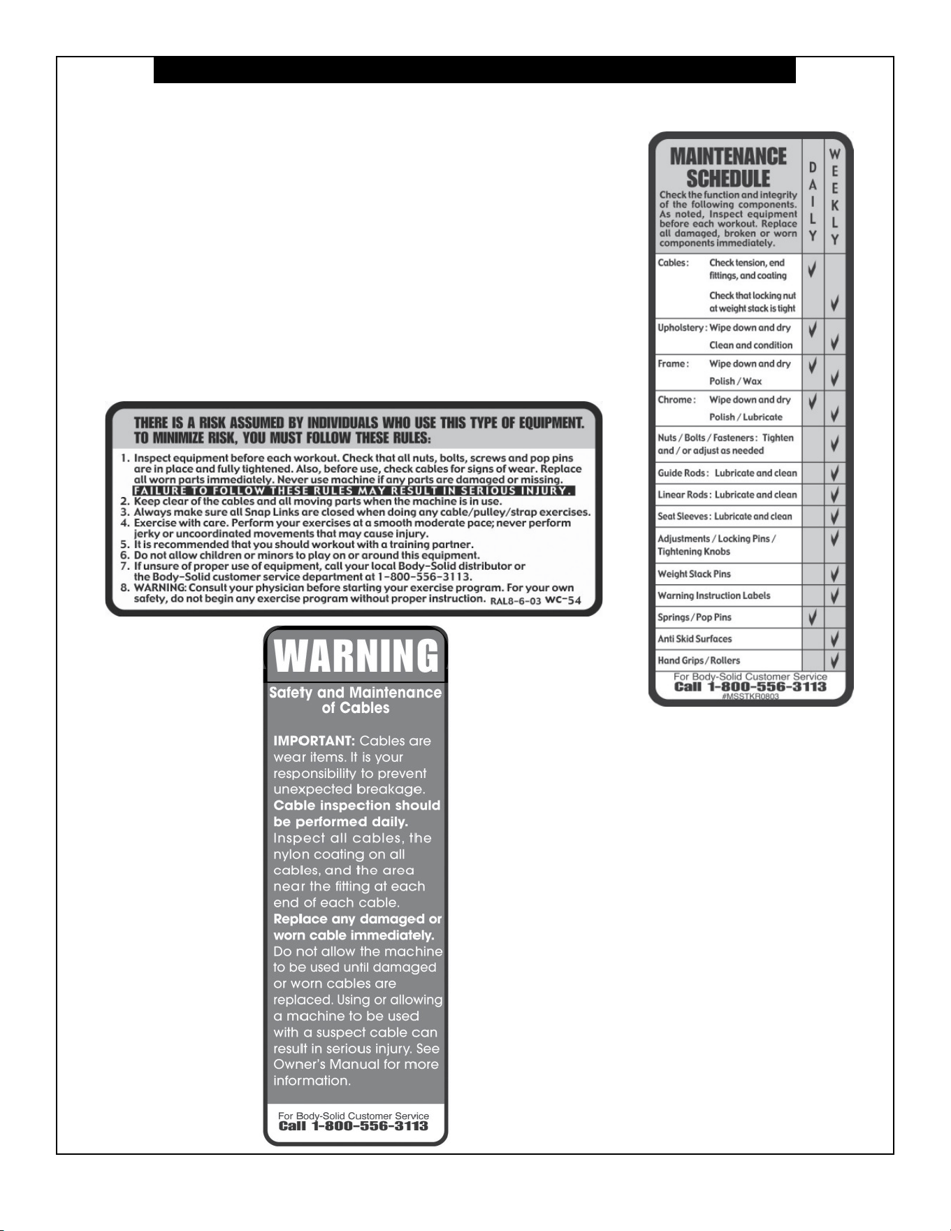
m IMPORTANT: Cables are wear items. It is your
responsibility to prevent unexpected breakage.
Cable inspection should be performed daily. Inspect
all cables, and the area near the fitting at each end
of each cable. Replace any damaged or worn cable
immediately. Do not allow the machine to be used
until these are replaced.
m Donotusetheequipmentoutdoorsornearwater.
Personal Safety During Assembly
m Beforebeginningassembly,pleasetakethetime
toreadtheinstructionsthoroughly.
m Readeachstepintheassemblyinstructionsand
followthestepsinsequence.Donotskipahead.
Ifyouskipahead,youmaylearnlaterthatyou
havetodisassemblecomponentsandthatyou
mayhavedamagedtheequipment.
m Assembleandoperateyour machineonasolid,
levelsurface.Locatetheunitafewfeetfromthe
wallsorfurnituretoprovideeasyaccess.
Your machine isdesignedforyourenjoyment.By
followingtheseprecautionsandusingcommonsense,
youwillhavemanysafeandpleasurablehoursof
healthfulexercise.
Afterassembly,youshouldcheckallfunctionsto
ensurecorrectoperation.Ifyouexperienceproblems,
rstrechecktheassemblyinstructionstolocateany
possibleerrorsmadeduringassembly.Ifyouareunable
tocorrecttheproblem,callthedealerfromwhomyou
purchasedthemachineorcall1-800-556-3113forthe
dealernearestyou.
Obtaining Service
PleaseuseyourOwner’sManualtomakesurethatall
partshavebeenincludedinyourshipment.When
orderingparts,youmustusethepartnumberand
descriptionfromyourOwner’sManual.Useonly
Body-Solidreplacementpartswhenservicingthis
machine.Failuretodosowillvoidyourwarrantyand
couldresultinpersonalinjury.
Forinformationaboutproductoperationorservice,
checkouttheocialBody-Solidwebsiteat
www.bodysolid.comorcontactanauthorized
Body-SoliddealeroraBody-Solidfactory-authorized
servicecompanyorcontactBody-Solidcustomer
serviceatoneofthefollowing:
Toll Free: 1-800-556-3113
Phone: 1-708-427-3555
Fax: 1-708-427-3556
Hours: M-F 8:30-5:00 CST
E-Mail: [email protected]
Or write to: Body-Solid, Inc.
Service Department
1900 S. Des Plaines Ave.
Forest Park, IL 60130 USA
Retain this Owner’s Manual for future
reference. If you need to order replacement
parts please be prepared to provide the
following information when contacting us so
that we can assist you better.
1. Model Number
2. Proof of Purchase
3. Place of Purchase
4. Serial Number (S/N)
5. Part # and Description
1
2
3
45
6
7
8
SCC1200G.1-082024
Page 1.1
SCC-1200G
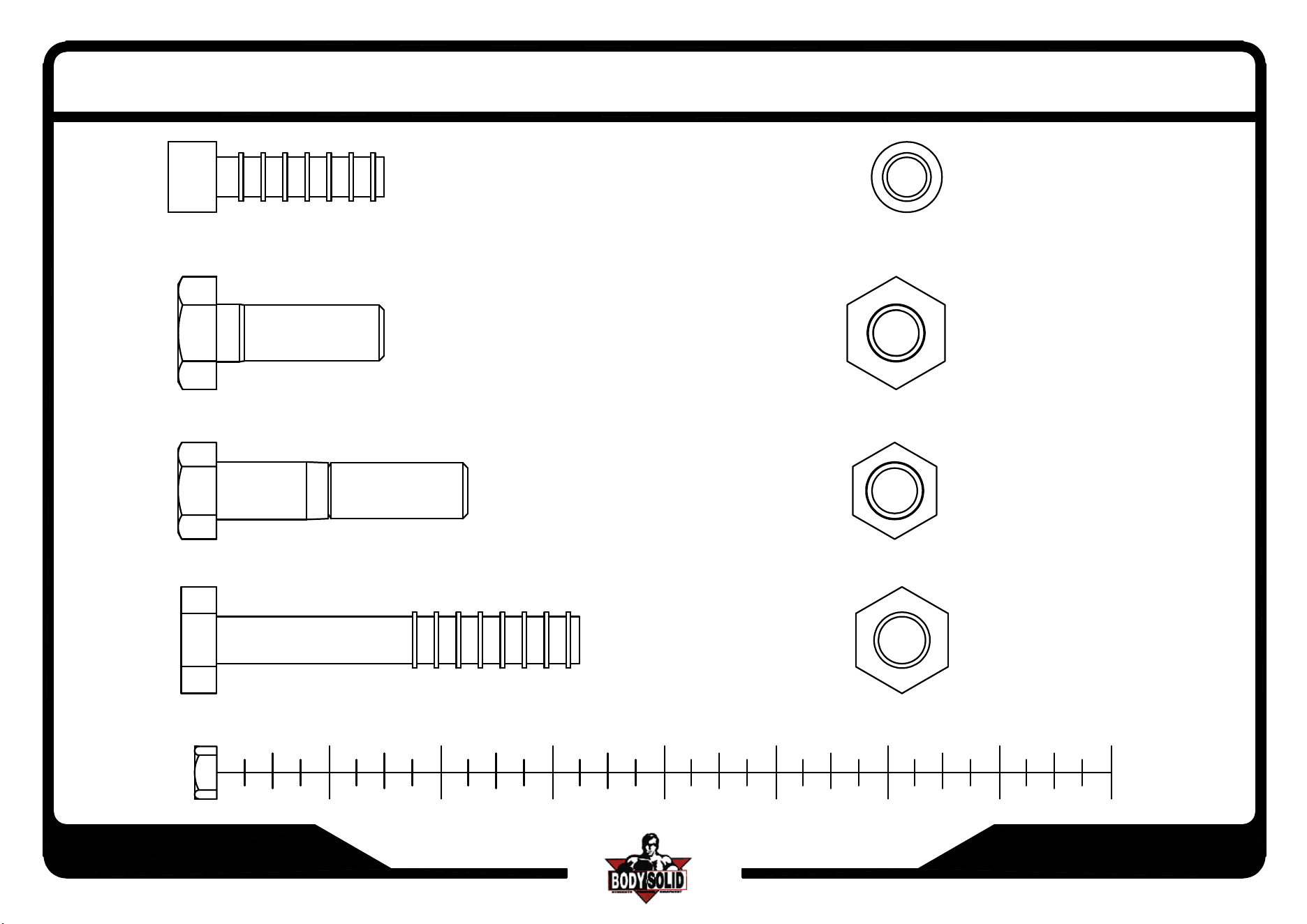
(A1)ROUND ALLEN HEAD 7/16"x1-1/2"L PARTIAL THREAD QTY.2
(A2)HEX BOLT 1/2"x1 1/2"L-13UNC PARTIAL THREAD QTY.2
(A3)HEX BOLT 1/2"x2 1/4"L PARTIAL THREAD QTY.8
(A4)HEX BOLT 1/2"x3 1/4"L PARTIAL THREAD QTY.14
ASSEMBLY INSTRUCTIONS
1
2
3
45
6
7
8
SCC1200G.1-082024
Page 1.2
SCC-1200G
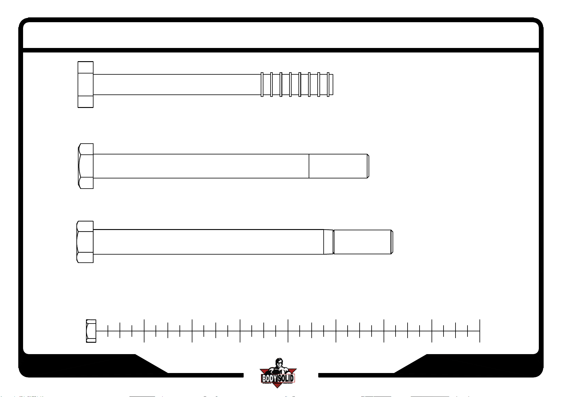
(A5)HEX BOLT 1/2"x5"L PARTIAL THREAD QTY.4
(A6)HEX BOLT 1/2"x5 3/4"L PARTIAL THREAD QTY.4
(A7)HEX BOLT 1/2"x6 1/4"L PARTIAL THREAD QTY.2
ASSEMBLY INSTRUCTIONS
1
2
3
45
6
7
8
SCC1200G.1-082024
Page 1.3
SCC-1200G
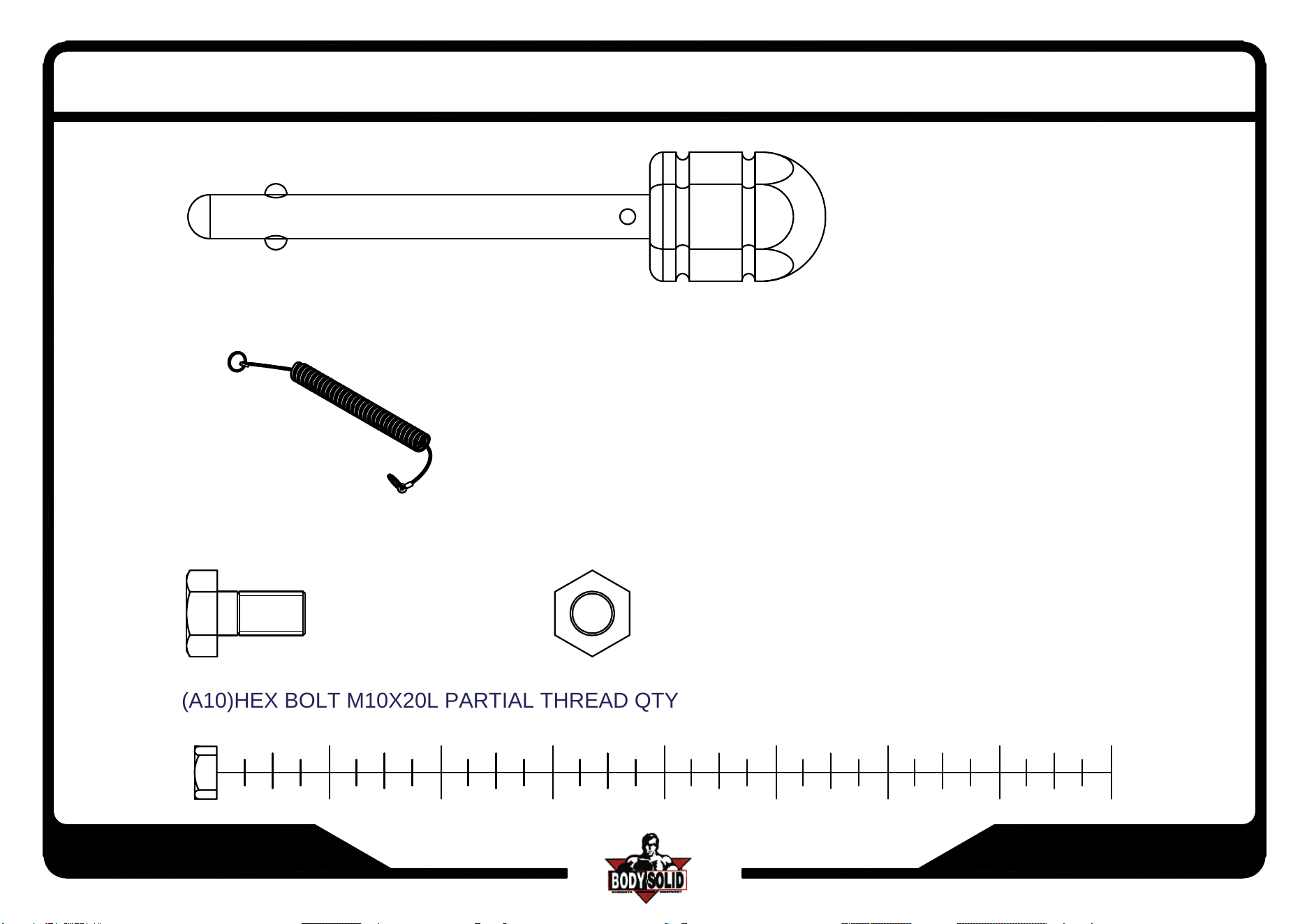
(A8)10LB PIN(8250-021) QTY.2
(A9)ELASTIC BOLT QTY.2
ASSEMBLY INSTRUCTIONS
(A10)HEX BOLT M10X20L PARTIAL THREAD QTY.6
SCC1200G.1-082024
Page 1.4
SCC-1200G
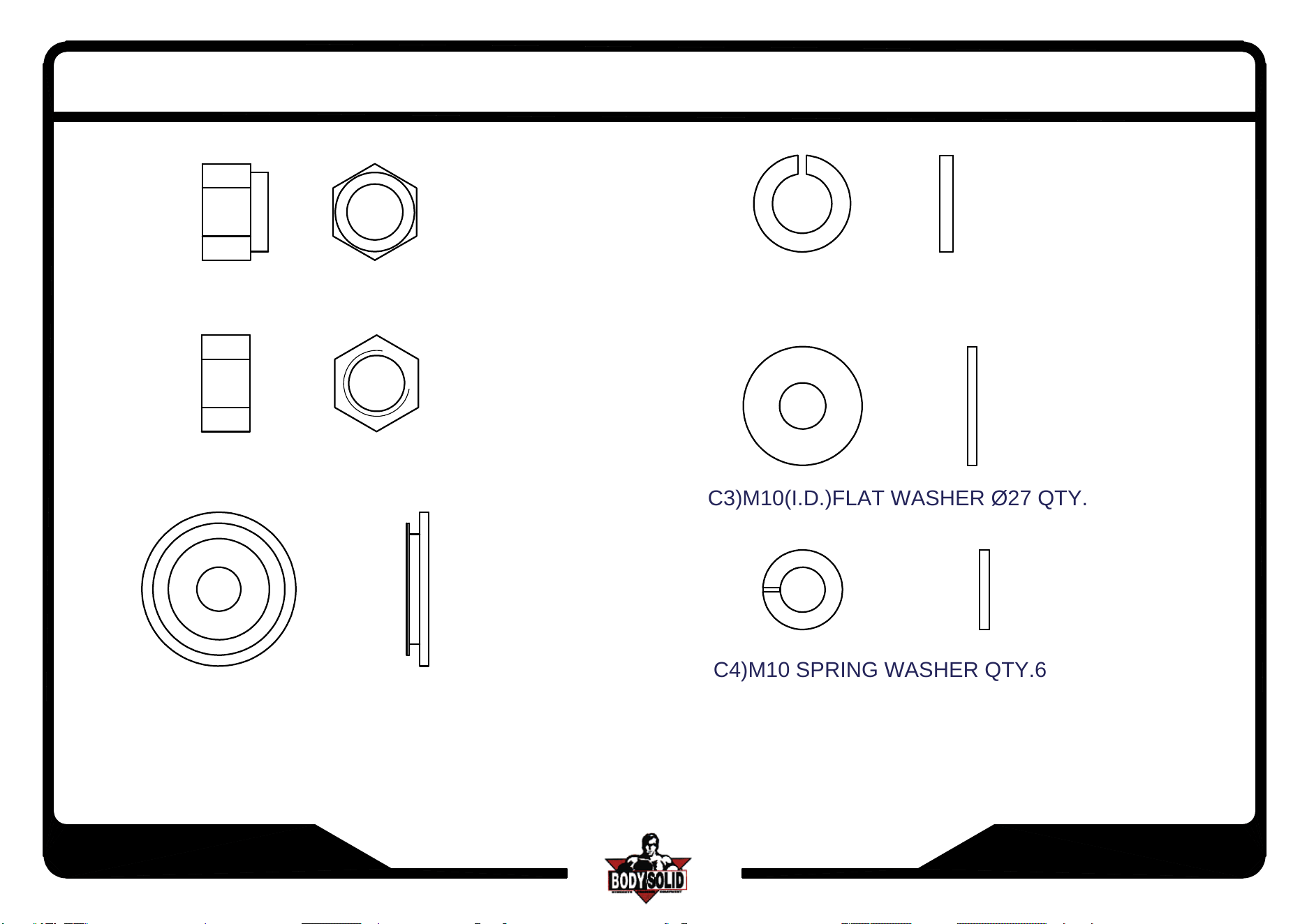
(B1)NYLON LOCK NUT 1/2" QTY.32
(B2)LOCK NUT 1/2"-13UNC QTY.2
(C1)1/2"(I.D.)ROUND END CAP WASHER QTY.60
(C2)1/2"(I.D.)SPRING WASHER QTY.2
ASSEMBLY INSTRUCTIONS
(C3)M10(I.D.)FLAT WASHER Ø27 QTY.6
(C4)M10 SPRING WASHER QTY.6
SCC1200G.1-082024
Page 2
SCC-1200G
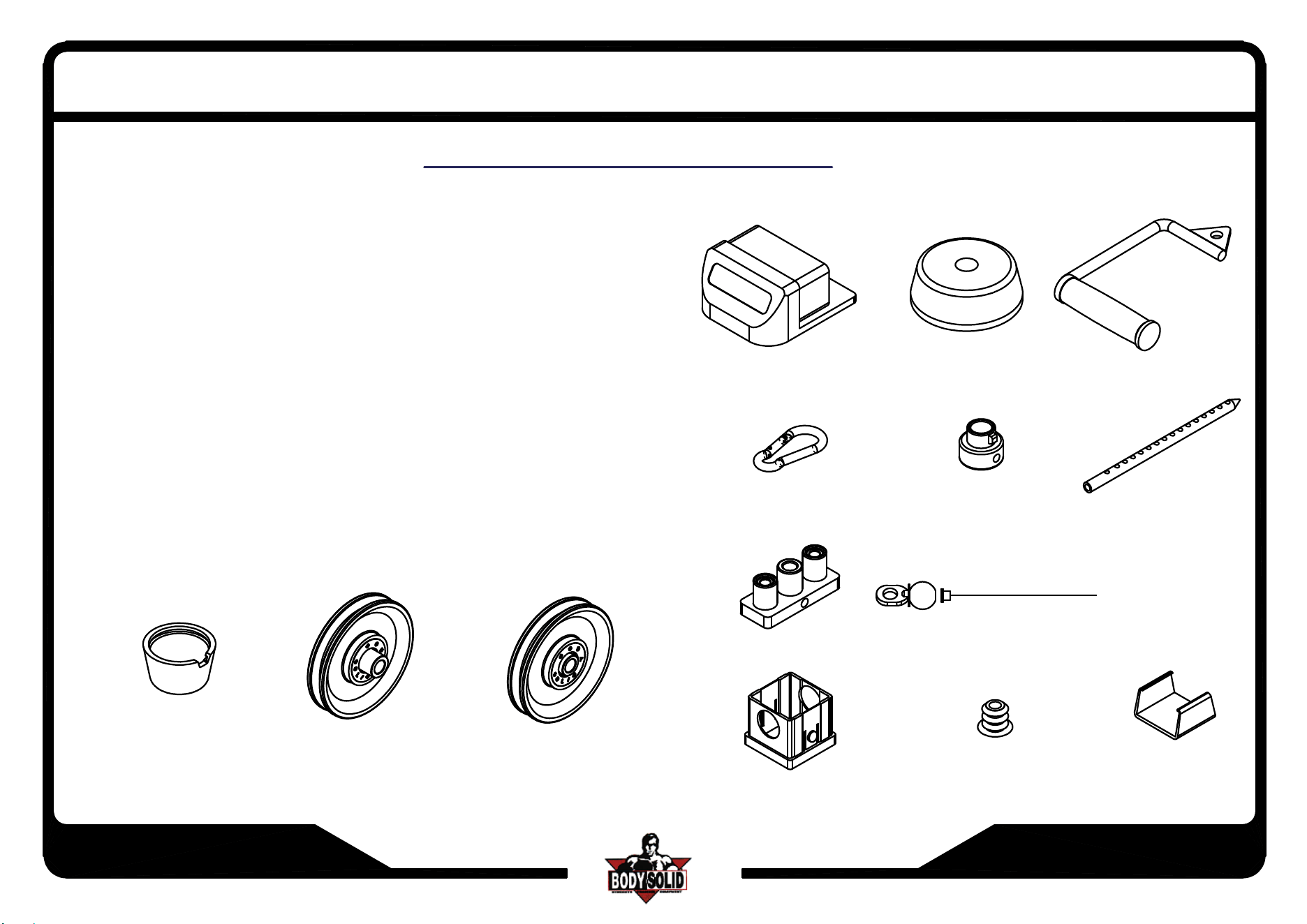
HARDWARE ILLUSTRATION
D1.1/2" BOLT CAP(9212-024)------------------------[60PCS]
D2.
4 1/2" PULLEY(9213-010A)-----------------------[6PCS]
D3.
4 1/2" PULLEY(9213-010B)-----------------------[8PCS]
D4.2"x4" FOOT CAP(9211-028)-------------------------[8PCS]
D5.
4" RUBBER DOUNT(9310-017)-----------------[4PCS]
D6.STIRRUP HANDLE(8290-002)---------------------[2PCS]
D7.SPRING SNAP LINK(8810-001)--------------------[2PCS]
D8.
3/4" SHAFT COLLAR(9211-050)----------------[4PCS]
D9.WEIGHT SELECTOR BAR(8220-061)-----------[2PCS]
D10.CHROME TOP PLATE(8400-002)---------------[2PCS]
D11.8300mm STEEL CABLE----------------------------[2PCS]
D12.60X50 NYLON BUSHING(9211-033)-----------[4PCS]
D13.
5/8" ROUND END CAP(9211-015)-----------[4PCS]
D14.2"x4" RUBBER DOUNT(9212-009)-------------[4PCS]
D4
D5
D6
D7
D8
D9
D1 D2 D3
D10 D11
D12
D13
D14
ASSEMBLY INSTRUCTIONS
SCC1200G.1-082024
Page 3
SCC-1200G
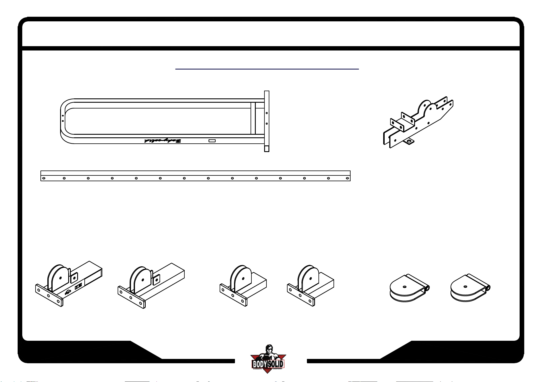
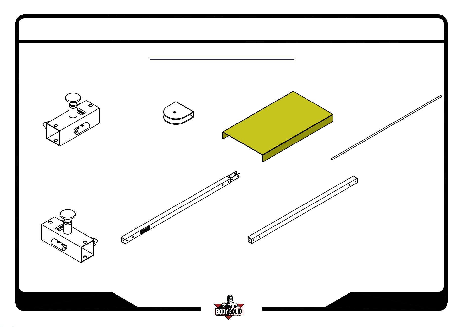
PARTS ILLUSTRATION SHEET
A[2PCS] WEIGHT STACK FRAME
B[2PCS]UPRIGHT PILLAR
D[2PCS] TOP PULLEY FRAME
E[2PCS] BOTTOM PILLAR FRAME
F[2PCS] BOTTOM PULLEY FRAME
G[2PCS]
MIDDLE PULLEY HOLDER
ASSEMBLY INSTRUCTIONS
SCC1200G.1-082024
Page 4
SCC-1200G
HARDWARE ILLUSTRATION
H[1PCS]
ADJUSTABLE CROSSOVER FRAME
I[4PCS]8280-004
CHROME GUIDE ROD
J[2PCS]8323-014
TOP PLATE PULLEY FRAME
L[2PCS]9220-009
PROTECT PLABK
ASSEMBLY INSTRUCTIONS
K[1PCS]
ADJUSTABLE CROSSOVER FRAME
M[1PCS]
N[1PCS]
50X2.5TX1370L

SCC1200G.1-082024
Page 5
SCC-1200G
CABLE CROSSOVER
NOTE: DO NOT TIGHTEN NUTS
AND BOLTS SECURELY UNTIL YOU HAVE COMPLETED ALL ASSEMBLY STEP
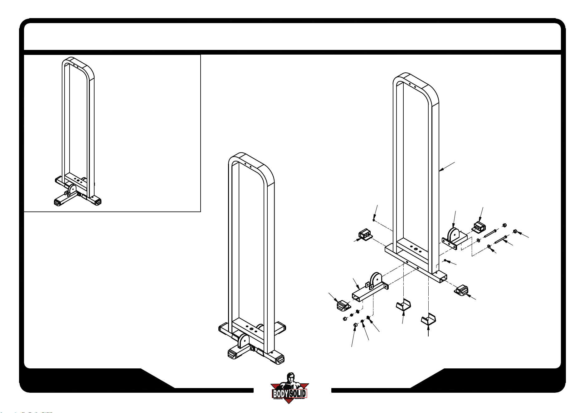
Step - 1
*Attach D14 Rubber Dount's to Bottom of A Weight Stack Frame.
*Insert D4 Foot Cap's into ends of E Bottom Pillar Frame,
F Bottom Pulley Frame and A Weight Stack Frame.
*Attach E Bottom Pillar Frame and F Bottom Pulley Frame to A Weight Stack Frame.
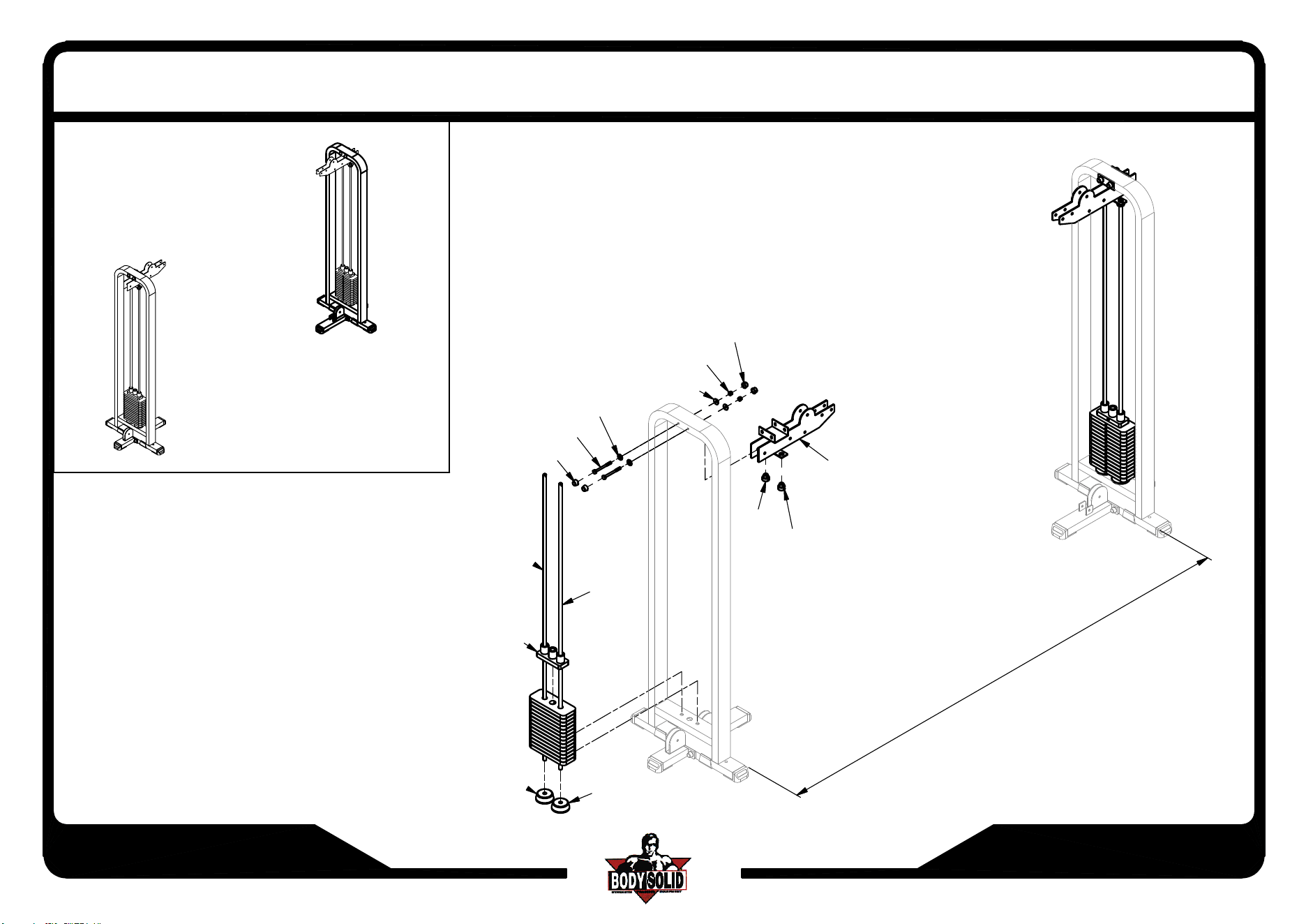
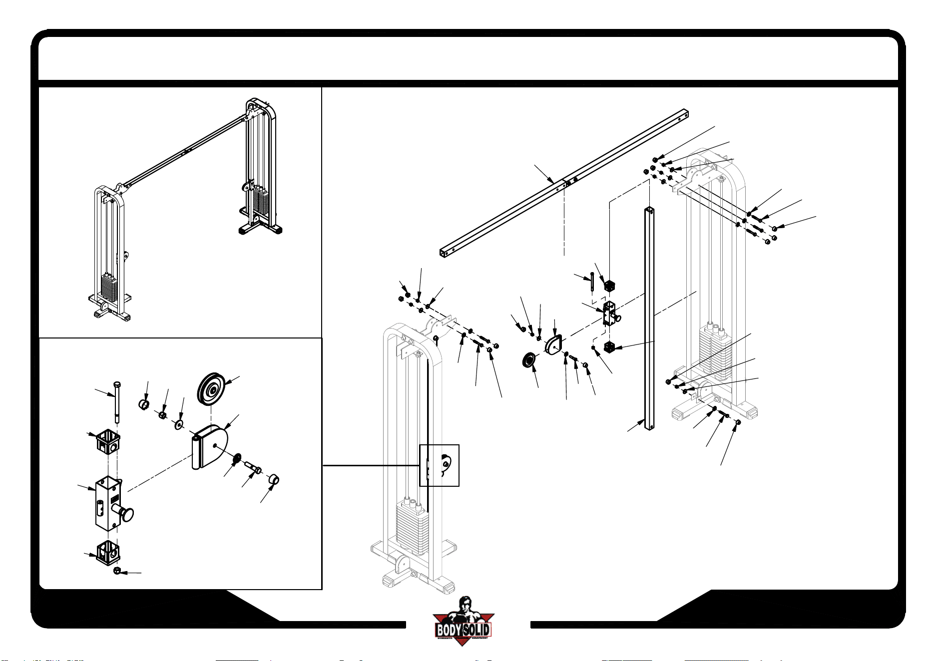
Step - 2
*Attach I Chrome Guide Rod's and D5 Rubber Donut's to A Weight Stack Frame.
*In this order slide Weight Stack, D10 Chrome Top Plate,
and D8 Shaft Collar's onto I Chrome Guide Rod's.
*Insert D Top Pulley Frame onto I Chrome Guide Rod's and then attach to A Weight Stack Frame.
*Insert D8 Shaft Collar's into D Top Pulley Frame.
*Repeat all the steps above in order to assemble opposite side.
Step - 3&4 - Use this step on both sides
*Attach D3 Pulley to G Middle Pulley Holder.
*Attach G Middle Pulley Holder to K or H Adjustable Crossover Frame.
*Insert D12 Nylon Bushing's to both sides of K or H Adjustable Crossover Frame.
*Slide K or H Adjustable Crossover Frame onto B
Upright Pillar - Pull red mushroom cap adjuster to slide on.
*Attach B Upright Pillar to E Bottom Pillar Frame and D Top Pulley Frame
*Attach C Top Cross Support to D Top Pulley Frame
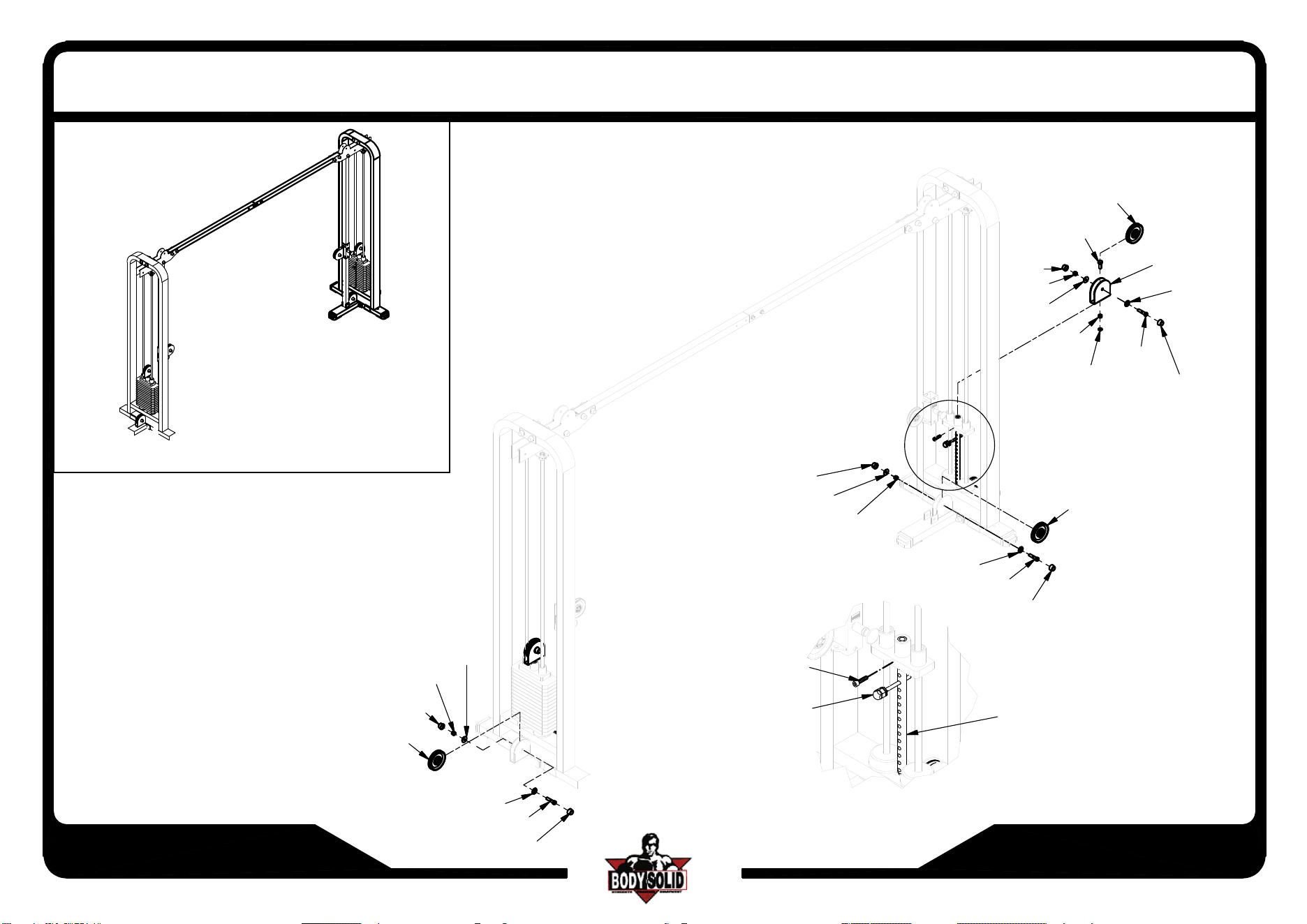
Step - 5 - Use this step on both sides
*Attach J Top Plate Pulley Frame and small ring of A9 Elastic Bolt to D9 Weight Selector Bar.
*Attach D3 Pulley to J Top Plate Pulley Frame.
*Attach D9 Weight Selector Bar to D10 Chrome Top Plate.
*Attach large ring of A9 Elastic Bolt to A8 10Lb. Pin.
*Attach D3 Pulley to E Bottom Pillar Frame.
*Attach D3 Pulley to F Bottom Pulley Frame.
SAFETY RULES
1. Periodically check that all nuts, bolts and screws are fully tightened on
your CABLE CROSSOVER MACHINE.
2. Exercise with care.Perform your exercises at a smooth moderate pace;
never perform jerky or uncoordinated movements that may cause injury.
3. It is recommended that you should workout with a training parther.
4. Warning:
CONSULT YOUR PHYSICIAN BEFORE STARTING YOUR
EXERCISE PROGRAM.IT IS ADVISABLE TO HAVE A PHYSICAL
EXAMINATION BEFORE YOU ENTER ANY EXERCISE PROGRAM.
FOR YOUR OWN SAFETY,DO NOT BEGIN ANY EXERCISE
WITHOUT PROPER INSTRUCTION.
ASSEMBLY INSTRUCTIONS
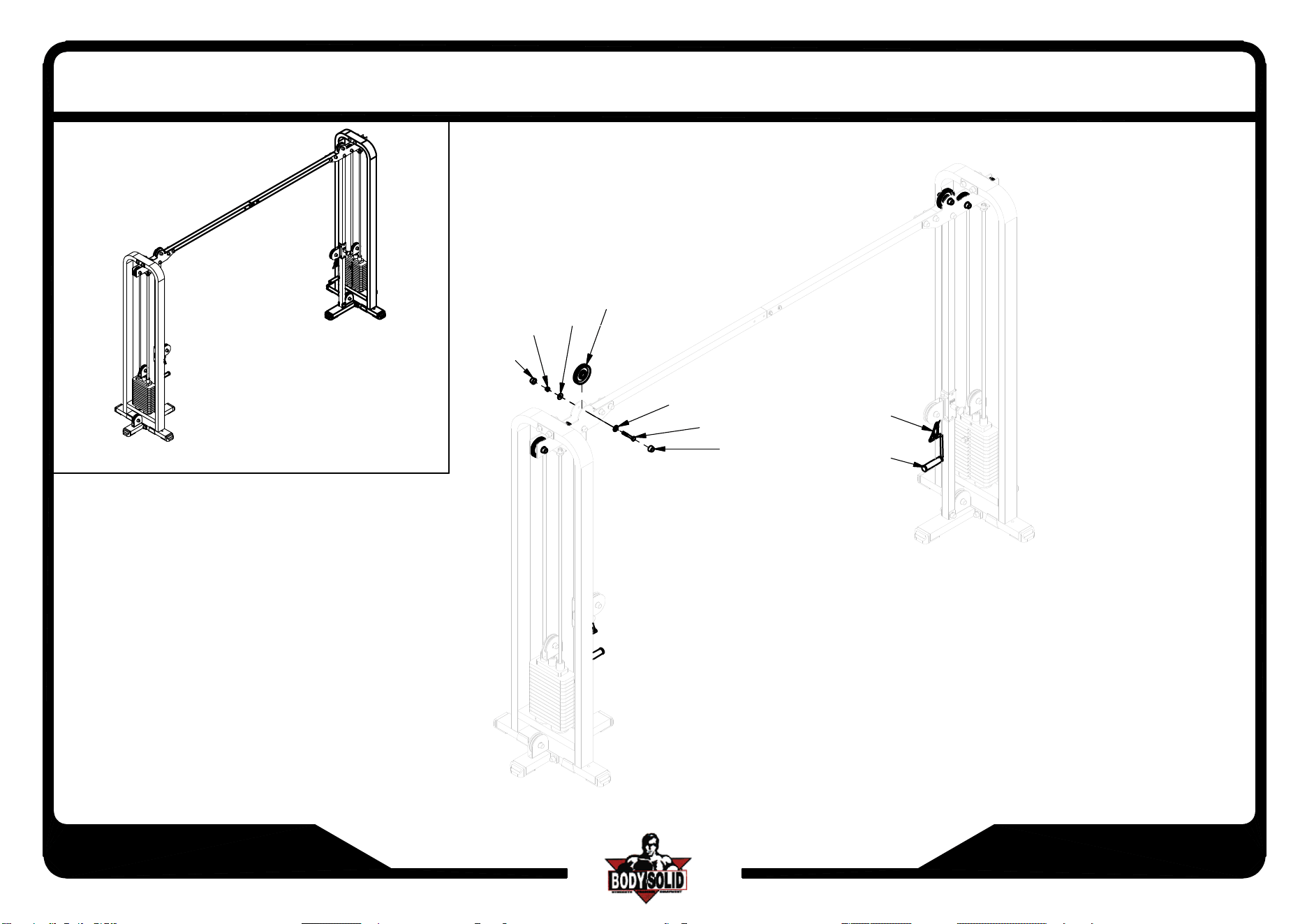
Step - 6 - Use this step on both sides.
*Attach D2 Pulley to inside of D Top Pulley Frame.
*Attach D3 Pulley to outside of D Top Pulley Frame.
*Attach D6 Stirrup Handle to H and K Adjustable Crossover Frame.
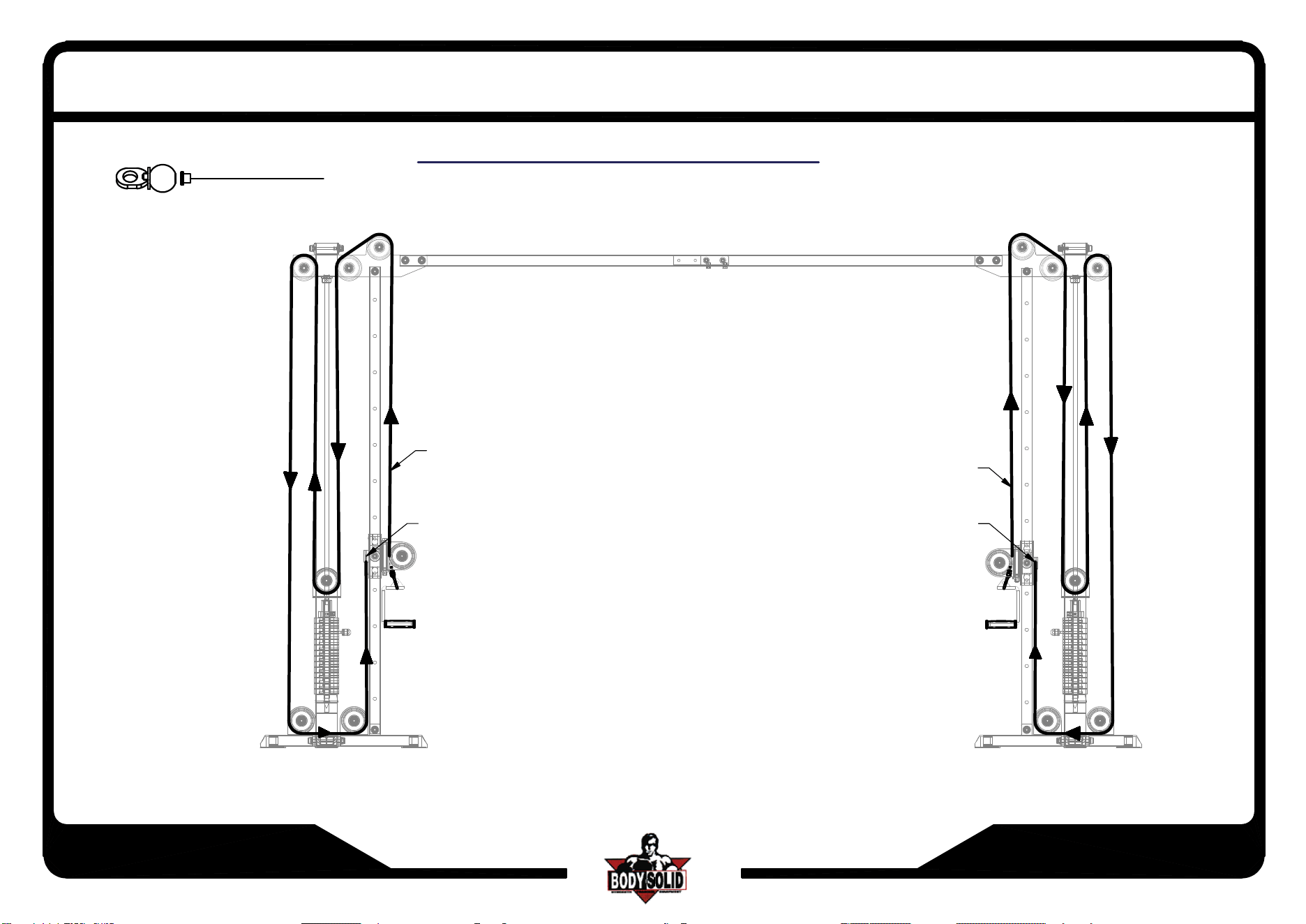
Step - 7
*Attach Cables as shown in cable routing instructions.
*Tighten all Bolts
*Attach all Bolt Caps and L Protect Plate.
SCC1200G.1-082024
Page 6
SCC-1200G
Above shows STEP 1
assembled and completed
ASSEMBLY INSTRUCTIONS
Fx2
D4x2
C1x4
A6x4
D1x4
D13x2
D4x2
D14x2
D14x2
D13x2
D4x2
Ex2
D4x2
C1x4
B1x4
D1x4
Ax2
PAGE 1
SCC1200G.1-082024
Page 7
SCC-1200G
Above shows STEP 2
assembled and completed
C1x4
B1x4
D1x4
C1x4
A5x4
Ix2
Ix2
D10x2
D5x2
D5x2
D1x4
D8x2
D8x2
Dx2
A
b
o
u
t 3
3
0
7
m
m
(
1
3
0
i
n
)
*:Before the assembling of the weight stacks:
Finish (step 1) and adjust the distance between
the two bases to 3307mm(130in)
ASSEMBLY INSTRUCTIONS
SCC1200G.1-082024
Page 8
.1
SCC-1200G
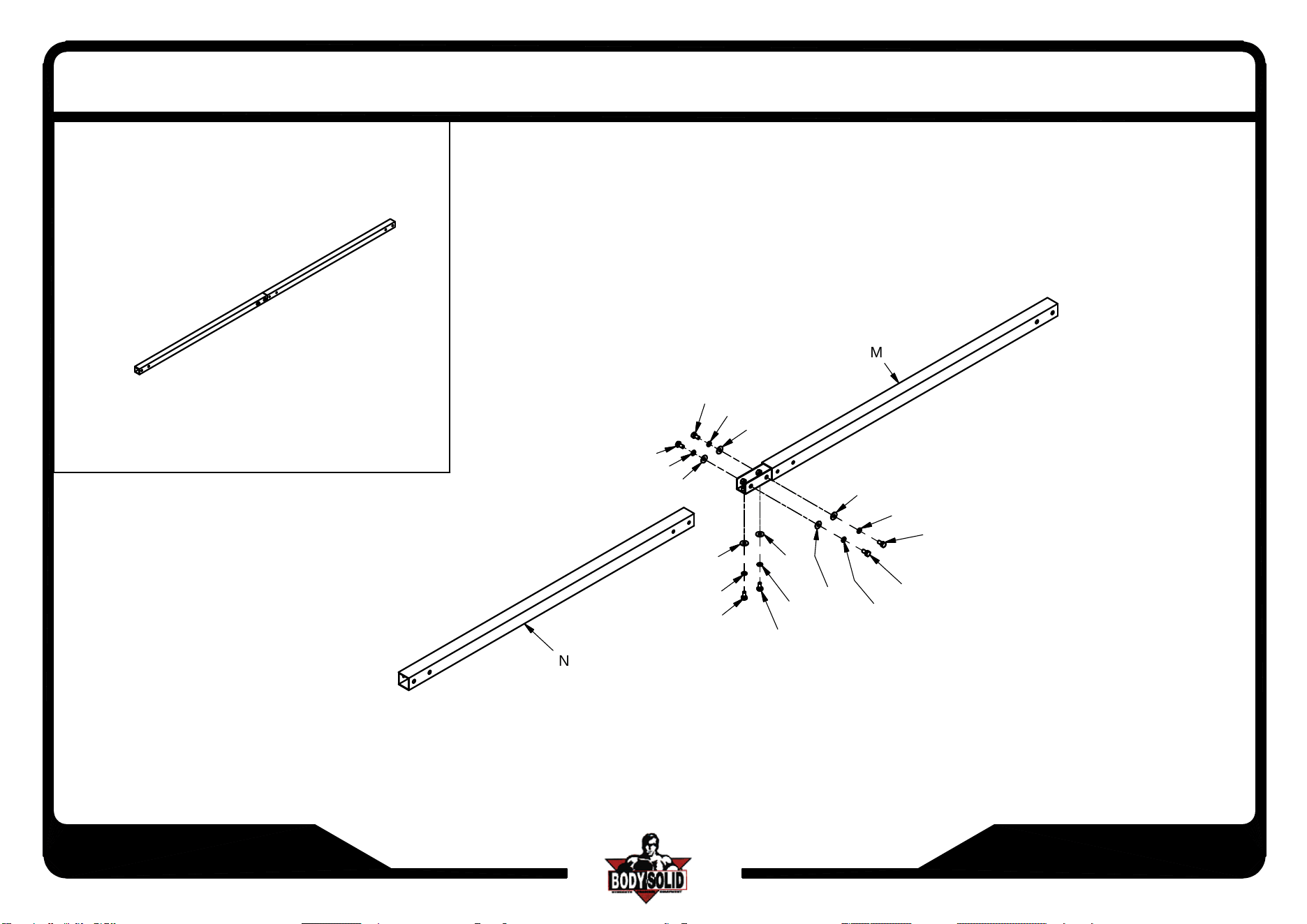
Above shows STEP 3
assembled and completed
ASSEMBLY INSTRUCTIONS
M
A10
C4
C3
A10
C4
C3
C3
C4
A10
C3
C4
A10
C3
C4
A10
C3
C4
A10
N
SCC1200G.1-082024
Page 8
.2
SCC-1200G
Above shows STEP 4
assembled and completed
PAGE 8.1
Bx2
D1x2
B1x2
C1x2
C1x2
A4x2
D1x2
A7
D12
D1
B1
C1
D3
C1x2
A4x2
D1x2
D1x2
B1x2
C1x2
C1x4
A4x4
D1x4
D1x4
B1x4
C1x4
D12
B1
C1
A3
D1
G
H
ASSEMBLY INSTRUCTIONS
A7
D12
K
D12
B1
C1
G
D3
A3
D1
D1
B1
C1
A
SCC1200G.1-082024
Page 9
SCC-1200G
Above shows STEP 5
assembled and completed
D3x2
D1x2
B1x2
C1x2
A3x2
D1x2
C1x2
D1x2
B1x2
C1x2
C1x2
A3x2
D1x2
D3x2
D3x2
A2x2
D1x2
B1x2
C1x2
Jx2
C1x2
B2x2
C2x2
A3x2
D1x2
DETIAL A
A1x2
A8x2
D9x2
ASSEMBLY INSTRUCTIONS
SCC1200G.1-082024
Page 10
SCC-1200G
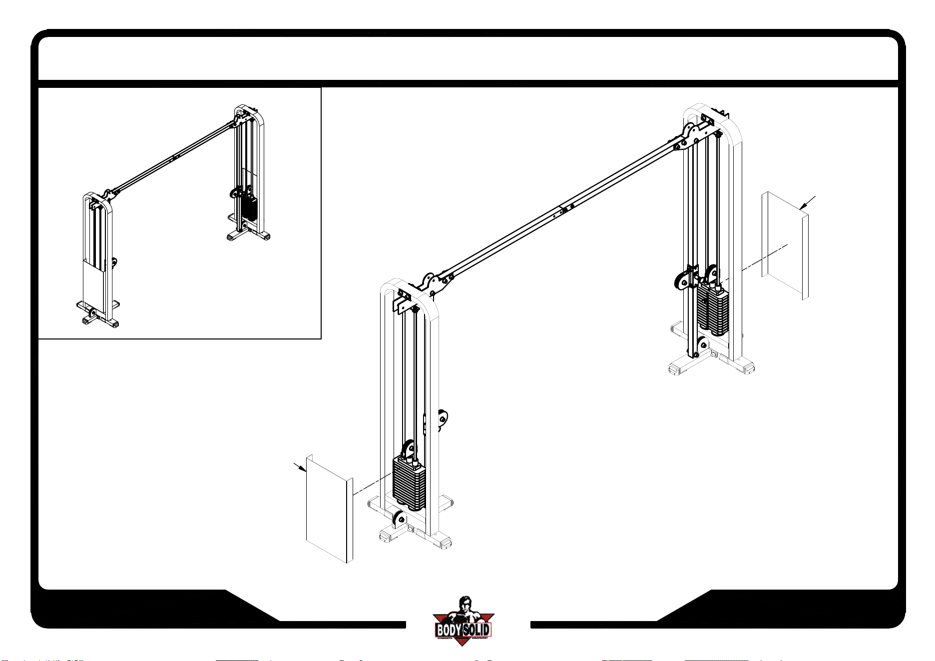
Above shows STEP 6
assembled and completed
D2x6
D1x6
B1x6
C1x6
A4x6
D1x6
C1x6
D7x2
D6x2
ASSEMBLY INSTRUCTIONS
SCC1200G.1-082024
Page 10.1
SCC-1200G
Cable to constitute illustration
D11
D11
D11
*:NEED TO LOOSEH BOTH ALLEN HEAD BOLT
IN ORDER TO REMOVE SHAFT
*
*
ASSEMBLY INSTRUCTIONS
SCC1200G.1-082024
Page 11
SCC-1200G
Above shows STEP 7
assembled and completed
L
L
ASSEMBLY INSTRUCTIONS