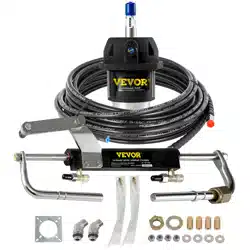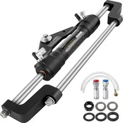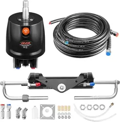

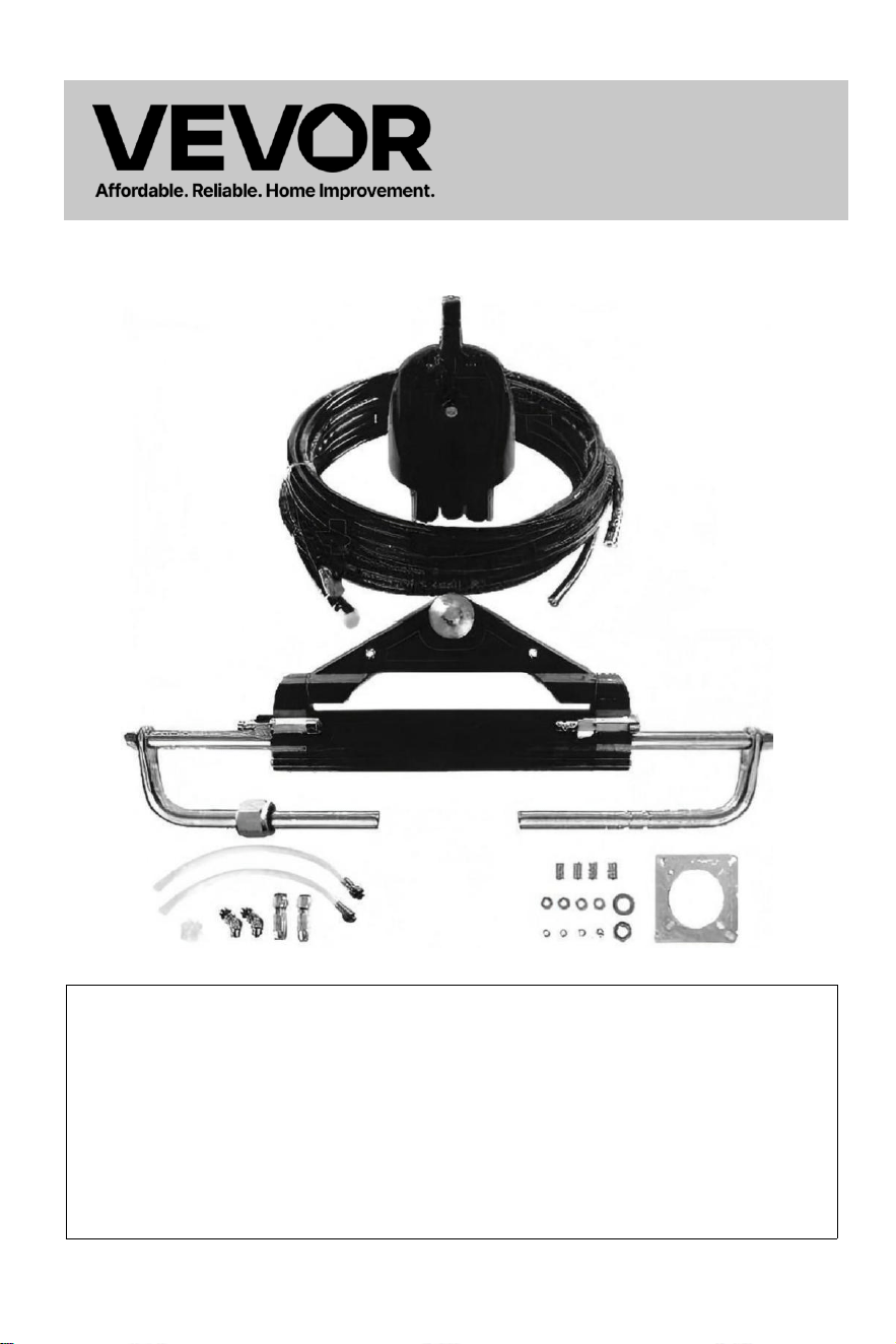
Hydraulic Steering For Boats
Model:YSH-150HP
- 1 -
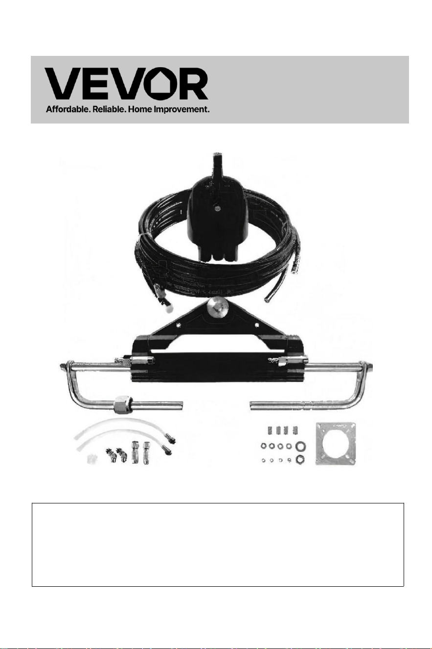
Hydraulic Steering
For Boats
Model:YSH-150HP
This is the original instruction, please read all manual instructions
carefully before operating. VEVOR reserves a clear interpretation of
our user manual. The appearance of the product shall be subject to
the product you received. Please forgive us that we won't inform you
again if there are any technology or software updates on our product.
- 2 -
Thank you for purchasing VEVOR hydraulic steering system.
This manual will elaborate the various functions of this system so that you
can fully experience the premium enjoyment this product can bring you.
VEVOR hydraulic steering system is based on the concept of modern industrial
design,the high efficiency,high transmission power piston pump technology is applied
to the design and manufacture of ship steering gear,which makes your steering
system more stable,smarter and more reliable.
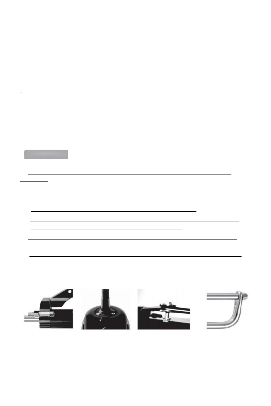
The main components of the steering gear are high strength aluminum alloy and
stainless steel which can be used in harsh marine conditions and extend the
longevity of steering gear.
The steering gear will relieve you from the heavy and inflexible mechanical shaft
steering,which can save your sore arms.It can enhance the pleasure of driving a
speedboat.
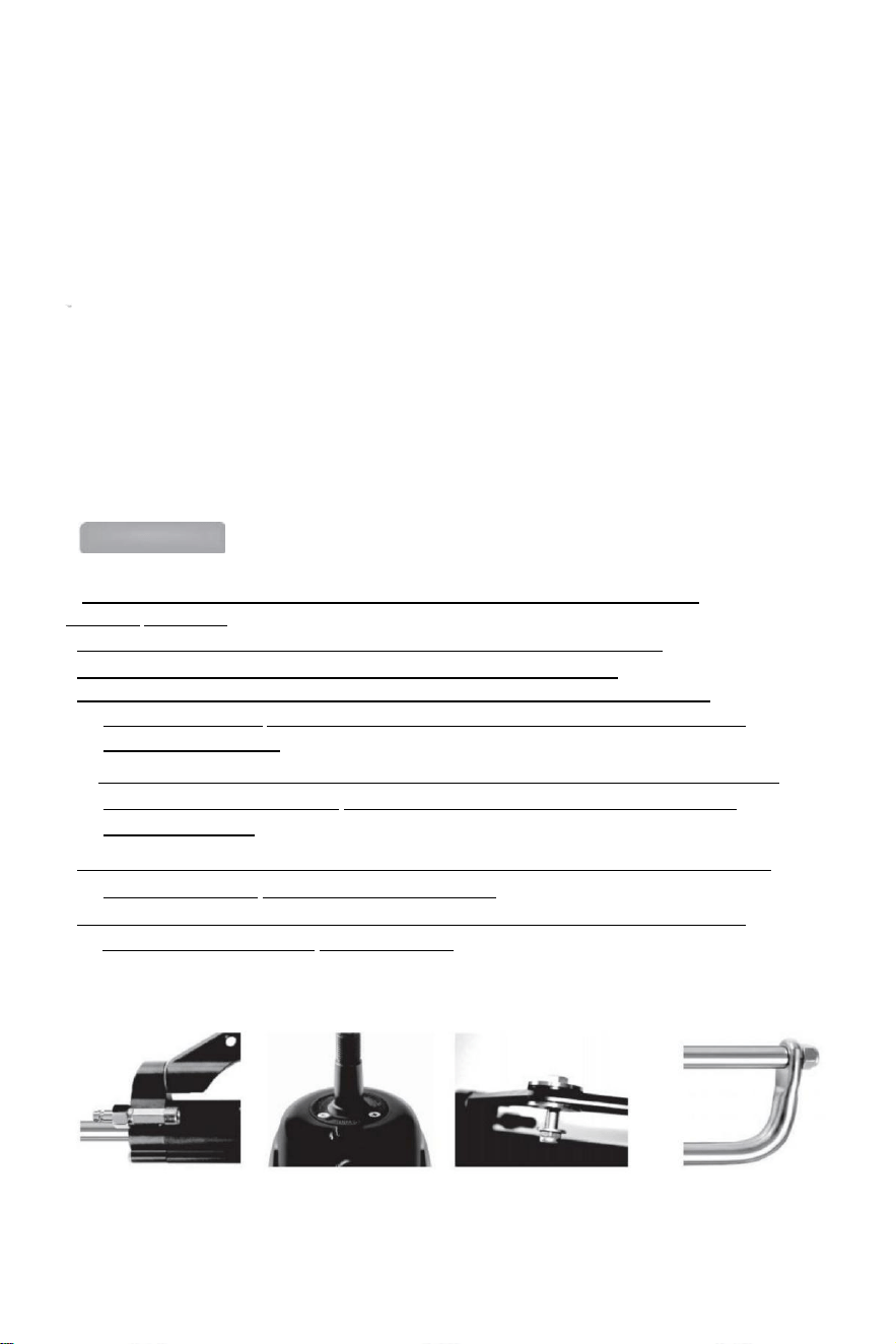
Main features:
● The steering pump is with compact inner structure and the fashionable and beautiful
appearance.
● Two-way Built -in locking valve eliminates the rebound torque.
● Easy to replace the shaft seal,user-friendly design;
● Steering shaft with special surface treatment not only has strength and reliability,but
also has the characteristics of wear resistance,corrosion resistance.
● High-strength aluminum alloy shell and surface treatment process can ensure its wear
and corrosion resistance and prevent water erosion effectively.
● Piping:High-strength nylon quick-fitting 1/4-pipe fittings makes the installation compact
and it is reusable.
● The use of custom high -standard hydraulic oil can improve the lubrication of parts and
seal protection.

- 3 -
General safety rules and warranty
This installation and maintenance manual is an integral part of the product
and must be fully understood by the user before installation.
The installation,maintenance and transfer of hydraulic direction system
components of VEVOR series of products must be done by the authorized and qualified
professional
technicians.VEVOR series of products implements the warranty for two years after-sales
service,when using the product,If there is any question or problem,please contact
the dealer in time.VEVOR will provide the correct guidance.VEVOR will not take
responsible for the consequences of unauthorized dismantling or disassembling.
Without the prejudice to the nature of the product,VEVOR has the rights to make
changes to the description information and illustrations contained in this manual,VEVOR
does not assume any responsibility for the adverse consequences caused by coping
this manual in any other illegal means which makes the user can't follow the
standard installation instructions.
Installation Precautions:
● Use components provided by VEVOR only,The parts supplied by the other
manufactures may cause safety hazards and affect the steering function;
●On all pipe connection threads,only seals such as Loctite PST or equivalent
sealant should be used.Do not use (banding)or similar sealing tapes,as this may allow
debris to enter the body of the pump and cause the blockage of the pipe.
●Please use 10#or 15#special hydraulic oil which is qualified and environment-
friendly. Using other oil(such as brake oil)instead may cause irreparable damage
to your equipment,causing loss of steering function and no warranty.
●The minimum bending radius of the pipe is 1"18(30CM).Do not touch the sharp
objects. Continued bending,rubbing,scratching or twisting may cause the pipe to be
damaged and rupture due to the normal steering pressure,thus causing loss of steering
function.
●Do not let the pipe drop freely when using,please use wire or other PVC material to
fix,so as to avoid potential safety hazard.
● Regular maintenance of system components and inspection of pipes and fittings for
wear or damage can prolong the usage life of your equipment.

- 4 -
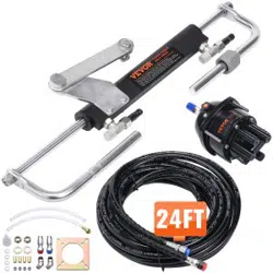
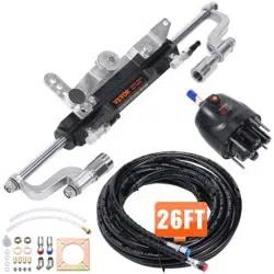
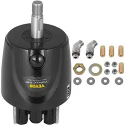
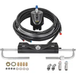
Packing list:
SKU
Model
Packing Accessories
High-
pressure
oil pipe
length
YYZXDB150HP0
5UTKJ001V0
YSH-
150HP
Hydraulic pump*1
Mounting plate*1
Instruction manual*1
Oiler pot*1
Oil filling tubes*2
135-degree elbow connector *2
Mounting bushings *4
1/4 washer*4
1/4-20UNC nuts*4
5/8-18UNF locknuts*2
5/8 washer*2
0
YYZXXTTJ90HPI
VK97001V0
YSH-
90HP
Hydraulic pump *1
Hydraulic steering cylinder *1
Mounting plate *1
135-degree elbow connectors *2
Quick connectors *2
Mounting bushings *4
1/4 washer*4
1/4-20UNC nuts*4
5/8-18UNF locknuts*2
5/8 washer*2
Transparent hose with connector *2
Plastic grease nipple *1
Instruction manual *1
Oiler *1
0
YYZXXTTJ90HP
DLO3P001V0
YSH-
90HP
Hydraulic pump*1
Hydraulic steering cylinder*1
High-pressure oil pipes*2
Mounting plate*1
135-degree elbows*2
Quick connectors*2
Mounting bushings*4
1/4 washer*4
1/4-20UNC nuts*4
5/8-18UNF locknuts*2
5/8 washer*2
Transparent hoses with connectors*2
Plastic grease nipple*1
Instructions*1
Oiler*1
20 ft
YYZXXTTJ90HP
WYCCR001V0
YSH-
90HP
24 ft
YYZXXTTJ150HI
HNTU001V0
YSH-
150HP
20 ft
YYZXXTTJ150H
3TSCX001V0
YSH-
150HP
24 ft
YYZXXTTJ150H
3E857001V0
YSH-
150HP
26 ft
- 5 -
Technical information:
TYPE
YSH-90HP
YSH-150HP
YSH-200HP
YSH-300HP-B
PUMPS
NR90
NR150
NR200
NR300
CAPACITY CM³
16
18
27
27
Wheel Thread
5/8"-18UNF
MAX PRESSION BARS
69
69
69
69
TURNS OF WHEEL
5
5.5
6
7
CYLINDERS
MR90
MR150
MR200
MR300-B
TUBE I.D[mm]
25
30
32
35
ROD I.D[mm]
14
16
16
18
OUTPUT FORCE/KGF
232
400
470
470
STROKE[mm]
200
198
200
200
VOLUME [cc]
67
101
125
142
APPLICATI ON
Up
to 90HP
Up to 150HP
Up to 200HP
Up to 300HP
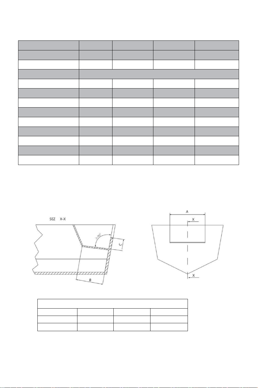
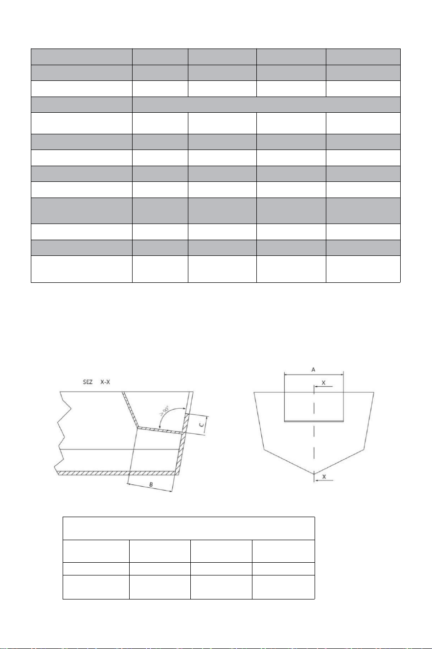
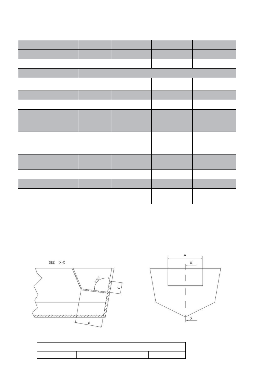
Minimum Splashwell Dimensions:
Before attempting installation,ensure that the splashwell of your
boat has the following minimum dimensions.
MINIMUM SPLASHWELL DIMENSIONS
Numberofengines
A
B
C
1
560mm-21.25"
152mm-5.98"
152mm-5.98"
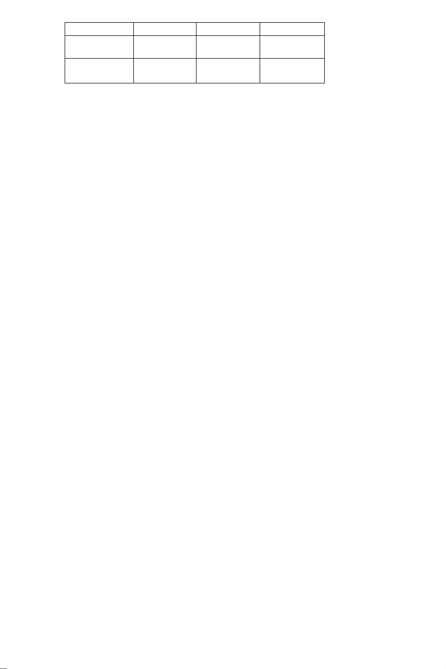
2
1110mm-21.55"
152mm-5.99"
152mm-5.99"
- 6 -
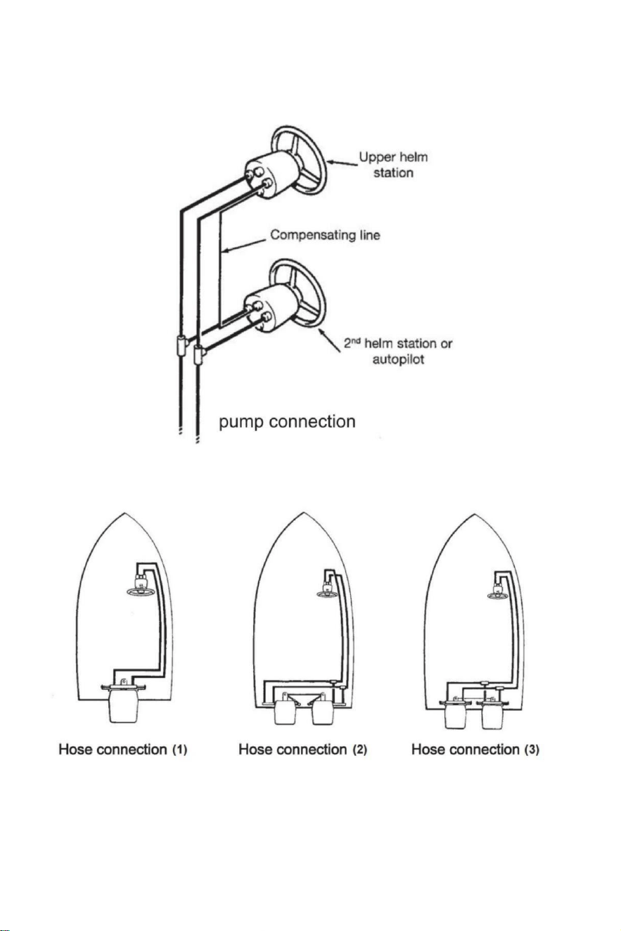
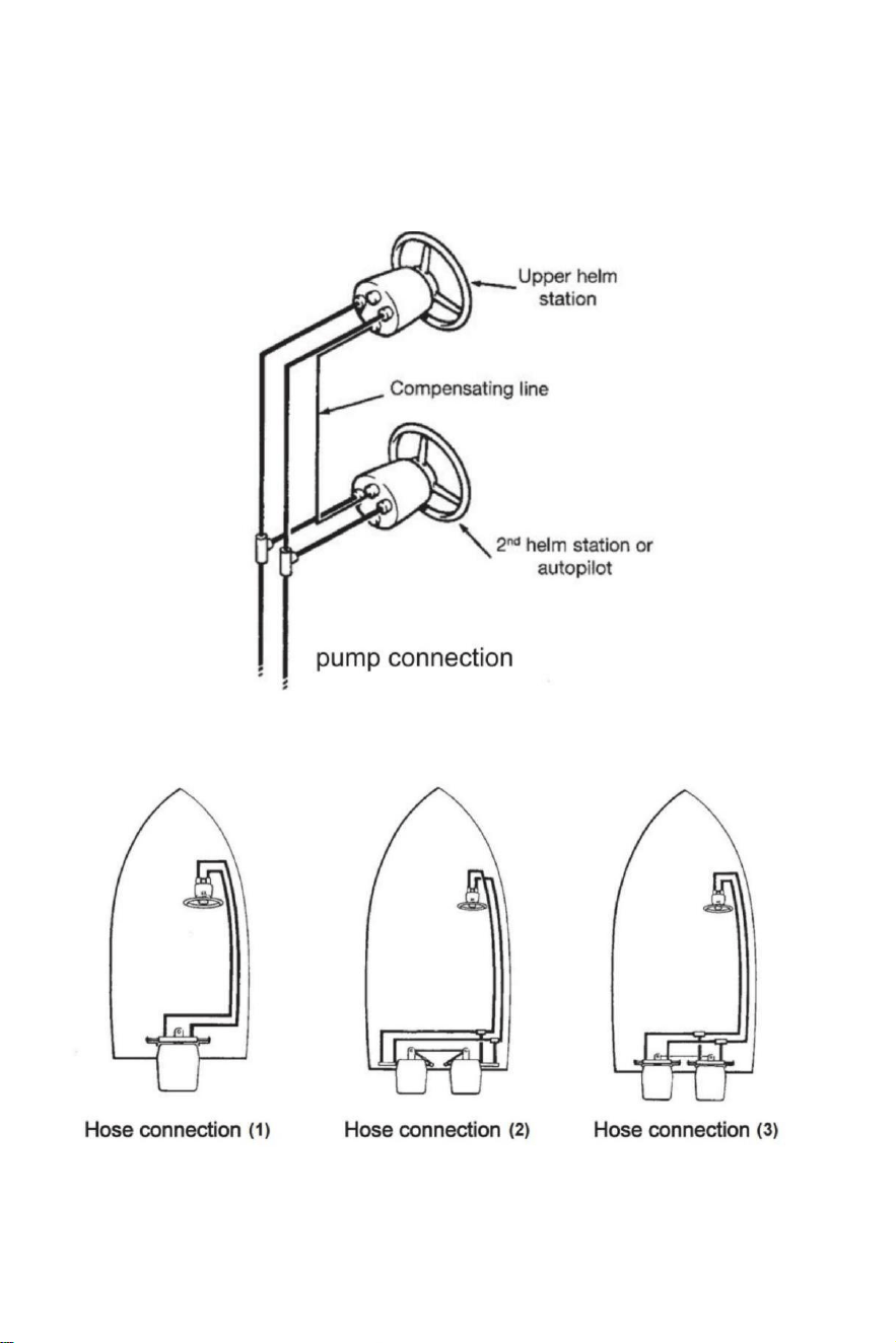
Hoses/fittings installation-pump connection
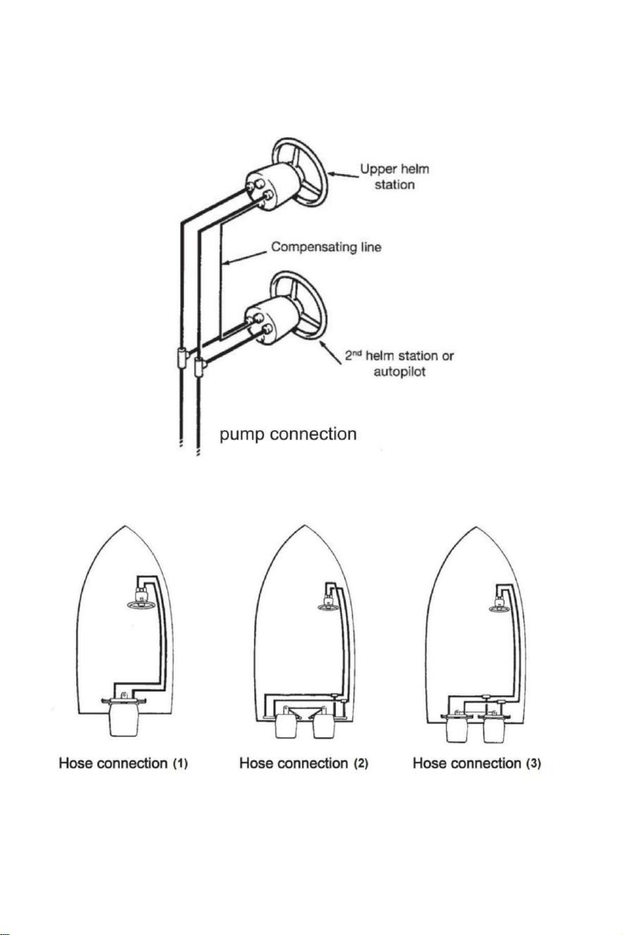
Refer to illustrations below for the correct connection of hoses from helm pump to cylinder.
Hose connection
- 7 -
Hose connection
Recommends the use of VEVOR steering hoses only.
Always try to route the hoses via the shortest path in order to avoid any possible loss of power.In
order to make the air bleeding of the system easier,it is suggested to mount the hoses
horizontally with an inclination of about 3 cm per meter;the pump side has to be higher than the
cylinder side.
Always protect the hoses that have to pass through a different compartment or use suitable
bulkhead connectors or sleeves.
Hose have to be installed in such a way they don't represent an obstacle for other components.
Do not remove protective end covers until the hoses have been routed and are ready to be
connected to the helm pump,hose fitting or steering cylinder(s).
Provide sufficient hose lengths to allow for cylinder movement throughout the turning arc and
up/down trim/tilt settings of the engine(s).
Throughout the hose installation,ensure the protective caps remain installed onto the end of the
hoses.
Attention:
Do not install hoses in an area where they will be exposed to high heat.Extreme heat
reduces the hose bursting pressure and can cause the hose melting.Exercise great
cleanliness.Make sure that pipes and hoses are perfectly clean and free from swarf.
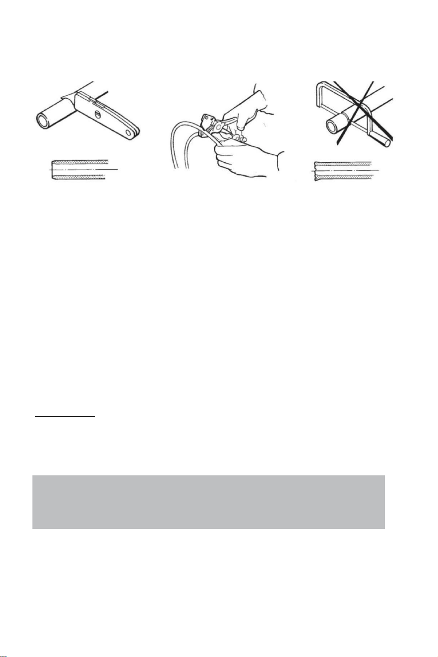
Note:
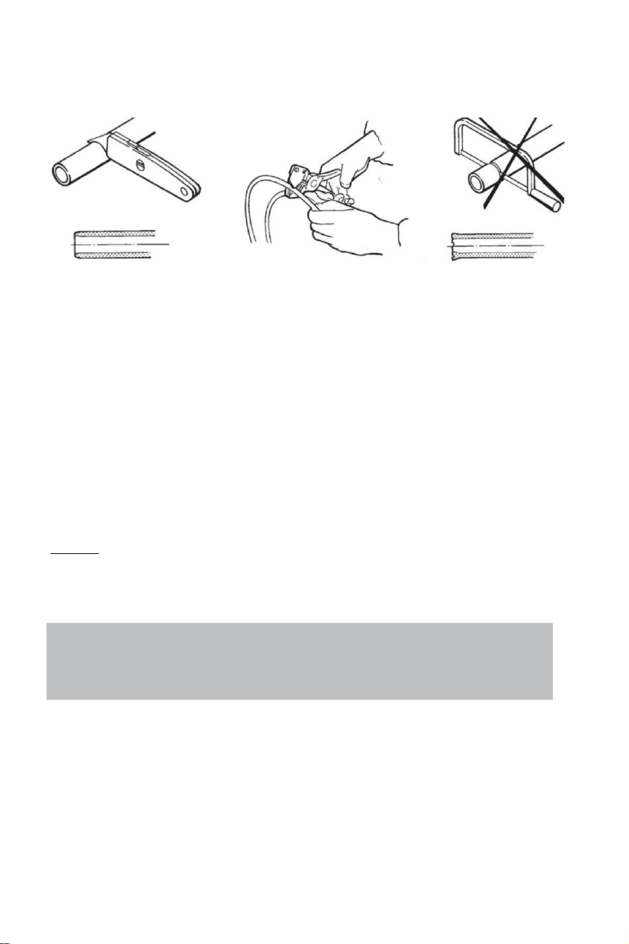
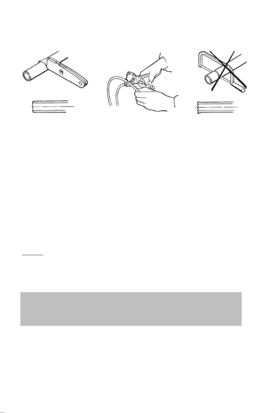
Flexible hoses have to be cut by means of a sharp knife;
never use a saw,as fragments of nylon in the hydraulic system cause serious problems.
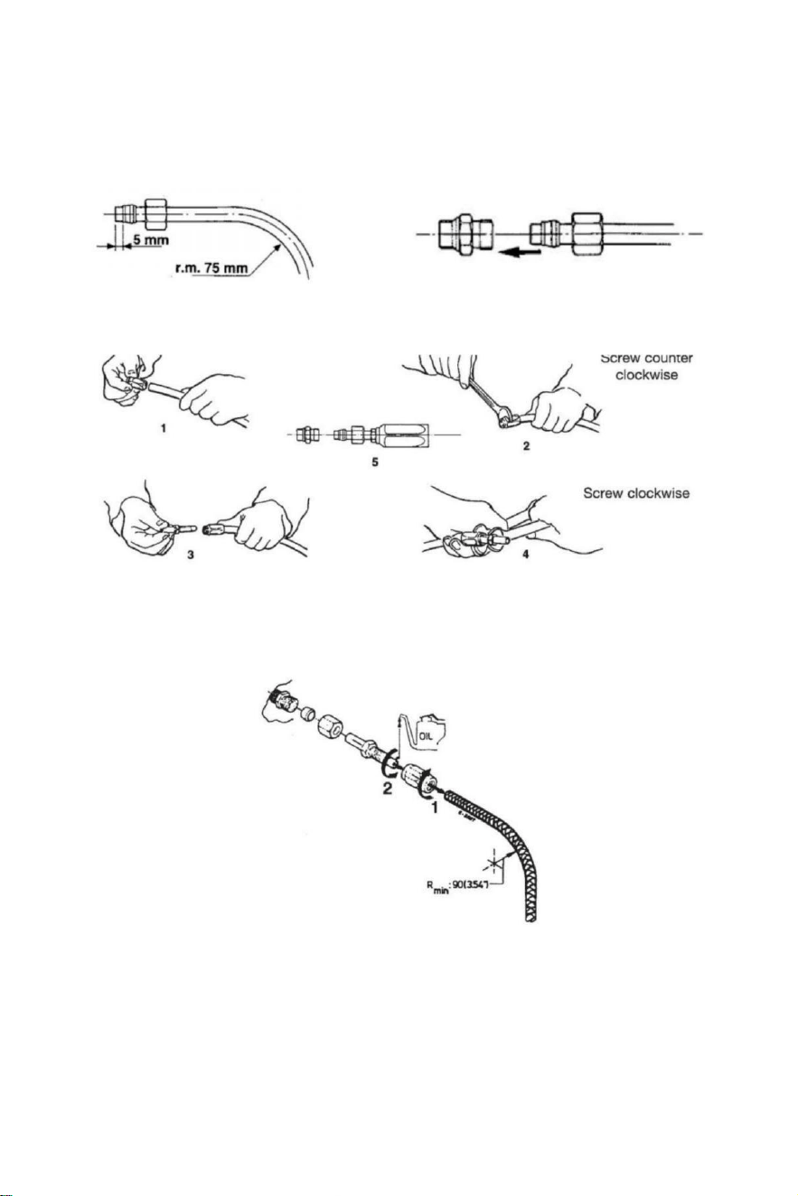
- 8 -
Hydraulic hose installation
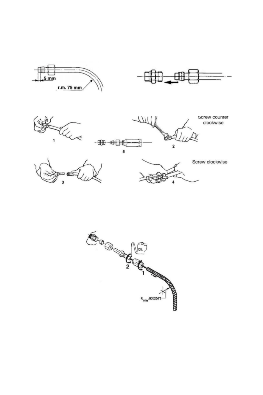
After cutting the nylon hose,fit the coupling nut and the support sleeve on the hose(check it
is properly in relation to the end of the hose).After the mounting of the nut,you have to
tight by means of a spanner.
Otherwise,you can mount nylon flexible hose with recuperable fittings.Do as the
illustrations below show.
After the installation clean the inside of the hoses by blowing through using compressed
air,in order to avoid any obstructions and to remove dust and debris from storage.Before
the air bleeding it is also suggested to make a rinsing of the system.Do not use water.
1 After cutting,screw the tube coupling sleeve onto the tubing(left-handed thread).
2 Oil the tube coupling and screw it into the sleeve.Make sure that the internal sheathing of
the tubing dose
not follow while tightening the screw!Also make sure that the internal
sheathing of the tubing is not squeezed while tightening the screw.
3 Check there is no internal interference putting a small screwdriver into the tube coupling
before proceeding with hose installation to helm or cylinder
- 9 -
Hydraulic Direction System YSH-150HP
Installation Tools (To complete the installation of this system ,
you need the following tools):
. Hole saw with 3 . 03 " (77MM) diameter
· 0 . 354 " (9MM) drill bit
· 1 . 181 " (30MM) mounting wrench
· 0 .433 " ( 11MM) installation wrench
· 0 . 748 " ( 19MM) installation wrench
· 0 . 669 " ( 17MM) installation wrench
· 0 .472 " ( 12MM) installation wrench
· 0 . 945 " (24MM) socket wrench
Important:
perform the bleeding procedure manually
and with the helm pump inclined no
more of 10(X).
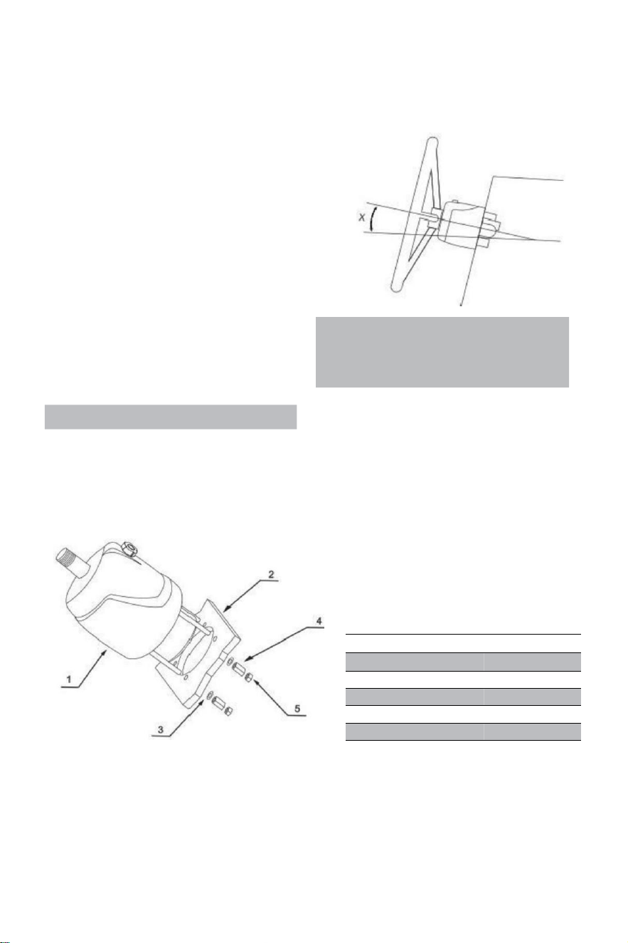
Steering pump YSH-150HP Installation:
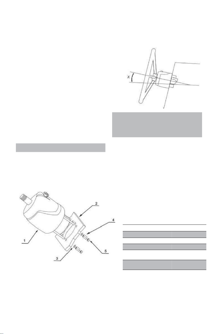
·Determine the angle and position you are installing to ensure that the steering wheel
does not interfere with other equipment.Check that there is still sufficient space behind
the bridge dashboard(2)for fitting and pipe connections.
RIF.
QUANTITY
DESCRIPTION
1
1
pump
2
1
Board
3
4
Shim
4
4
Extension nut
5
4
Lock nut
- 10 -
·Attach a1:1 access hole mounting template(included with this manual)to the instrument panel,and
position the mounting hole as standard with a hole cutter.
·Drill a 3.03"(77MM)diameter hole and drill four 0.354(9MM)diameter holes as shown on
the mounting template.
·Route the arranged tubing through the middle 3.03"(77mm)diameter hole and connect it to the
steering pump (1)
·Install the steering pump on the instrument panel with 4 washers(3)and 4 strain-relief nuts(4),4 lock
nuts(5), tightening torque≤15N.
·Lubricate the taper section of the shaft.Install the semicircular key.Place the steering wheel in the
direction shaft and the steering wheel key way on the semicircular key.Place the shim and
tighten the steering lock nut. The tightening torque is ≤20 Newton.
Note:
·The steering pump should be mounted at a tilt angle of X≤20°.If it is exceeded,it
may cause air to enter the duct and affect the steering function.
·Only use self-locking fasteners provided by VEVOR or standard fasteners.Using non-self-
locking fasteners instead may cause the equipment to loosen or separate.
·Do not open the pump cover or filler cap when installing the steering pump to prevent dirt
and chips from entering the pump and causing the steering function.
·Teflon-like ribbon seals can not be used on pipe nipples,which may cause tape chips to enter
the pump body and thus affect the steering function.(The VEVOR series is a pipe thread
sealing technology that does not require the use of other sealing tape seals.)
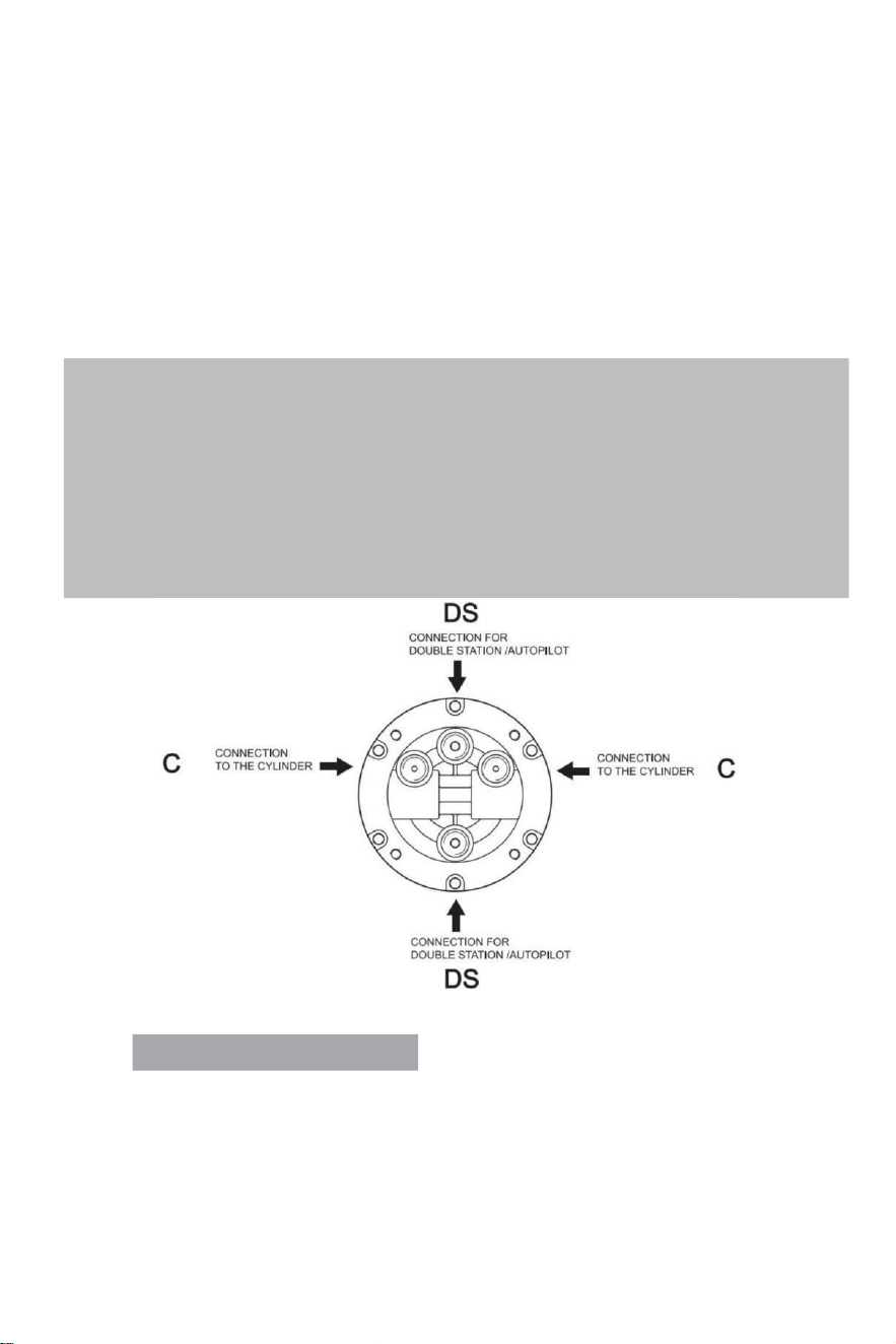
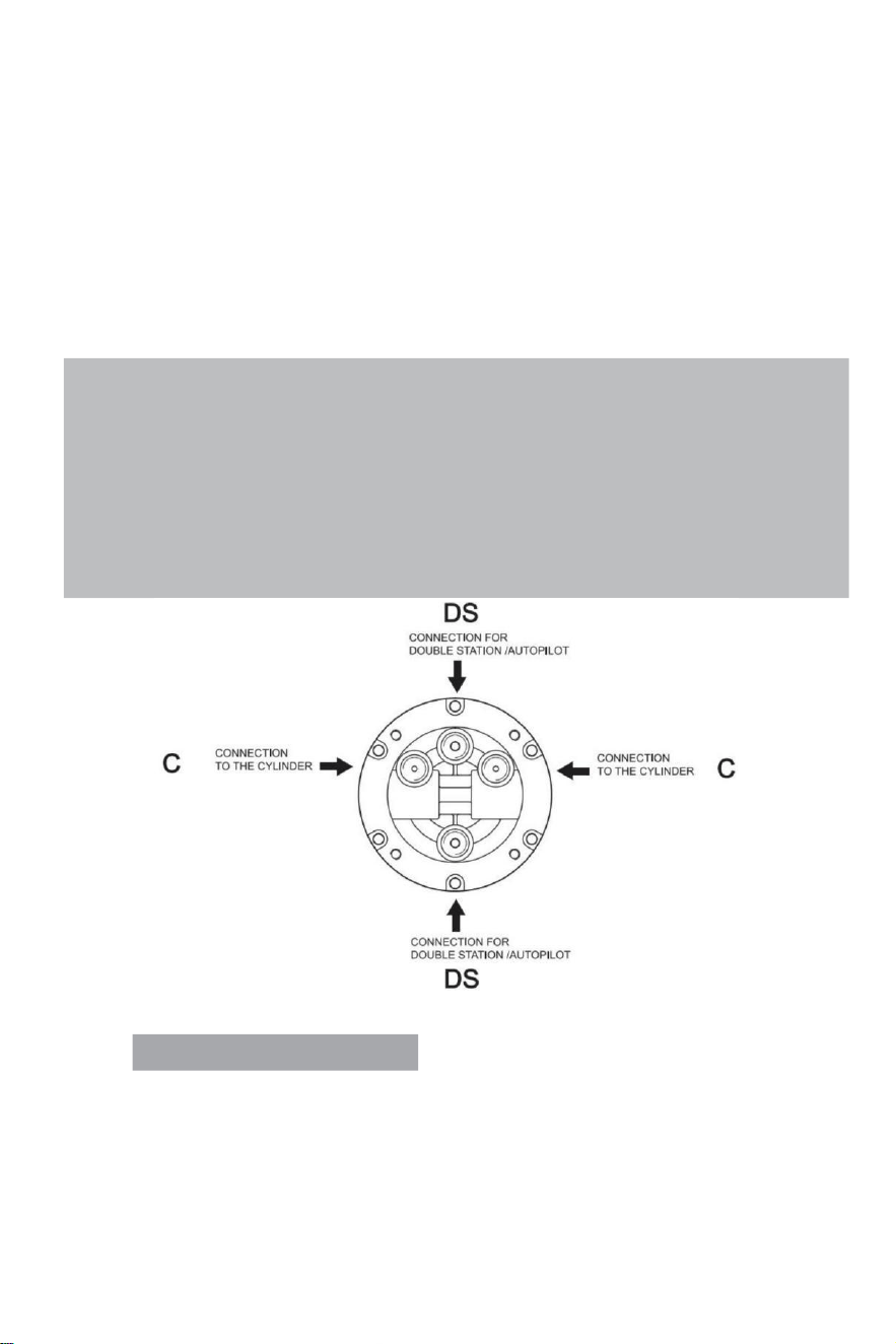
VALVE PORTS CONNECTION:
Port marked“C”:connections to the cylinder/s
Port marked“DS”:connections to the additional station or autopilot
- 11 -
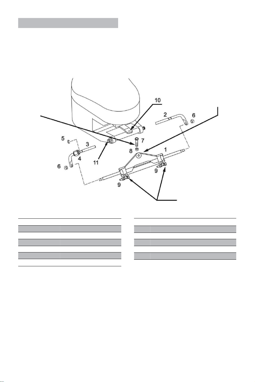
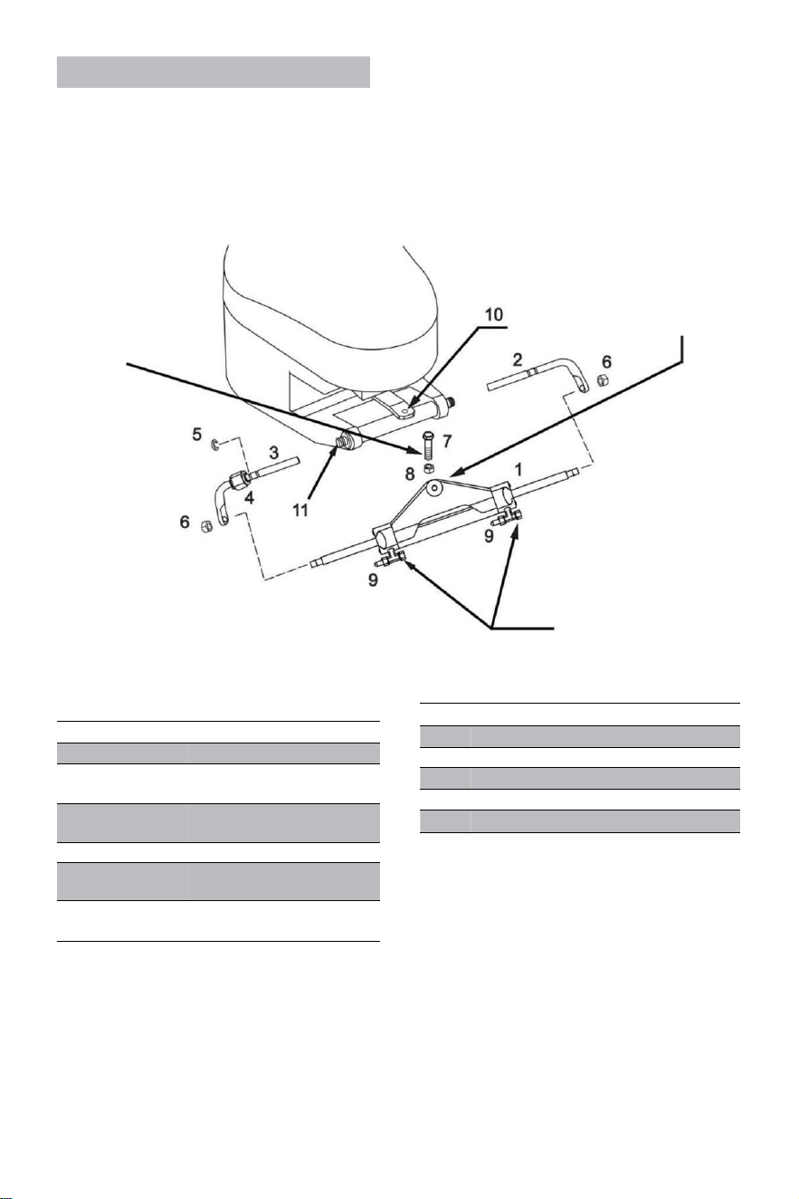
Cylinder YSH-150HP Installation:
WARNING:
It is important to check
periodically,at least every 3
months(or every month for
professional uses),the right
torque of this bolt and of the
lock nut.
The cylinder arm should
be attached of the engine
tiller arm on most brands
of outboards in the event
that the tiller interferes with
other parts of the outboard,
then it can be mounted under
the tiller instead.
WARNING:
Remove the red caps in order
to install the hose's fittings.
RIF.
QUANTITY
DESCRIPTION
1
1
Cylinder
2
1
Right support brackets
3
1
Left support brackets
4
1
Connecting nut
5
1
Stainless steel (C)buckle
6
2
Piston rod locking nut
·Before trying to install,please check whether your engine is suitable for this type of
cylinder,and ensure that your stern board space is of sufficient size for installation.
·Before installation,please lubricate the movable connection parts of the engine and the
cylinder
and the piston rod with qualified marine lubricant,and straighten your engine to the middle
position;
·
RIF.
QUANTITY
DESCRIPTION
7
1
3/8 connecting bolt
8
1
3/8 Lock nut
9
2
Deflation device
10
1
Engine connecting block
11
1
Engine mounting hole
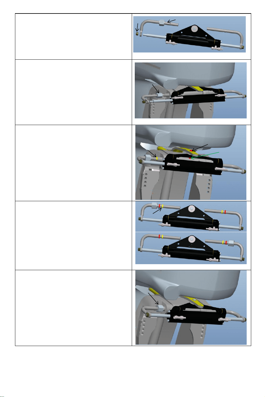
- 12 -
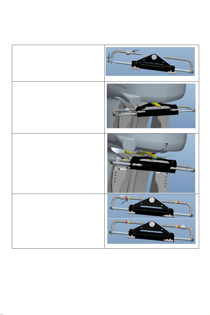
Loosen the self-locking nut(6)on one end of the
cylinder piston rod,and remove the installation
rod (3).After removing the parts,installthe
installation rod (3)into the engine installation
hole(as shown in the figure above);
Remove the bolt (7)from the middle hole of the
cylindrical triangle bracket bracket,adjust the
Angle of the engine,and fix the cylinder triangle
bracket to the engine with bolt(7)and nut(8)
corresponding to the hole on the engine
connection plate.Pay attention to the left and
right swing of the machine to ensure that the
cylinder will not interfere with the movement of
the engine after installation.
Adjust the engine Angle and cylinder piston rod
extension length.According to the gap between
the engine and cylindercorrectly install the
stainless steel C-clamp(5)into the appropriate
groove of the mounting rod.(See figure
above)
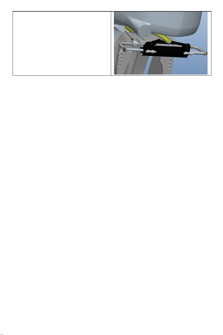
After installation,the locking nut(4)should be
tightened to eliminate the operating clearance of
the cylinder.This willenhance your experience.
6
3
4
5
7
8
5
4

- 13 -
·After the installation is complete,push your engine to the left and right to make a trial run of
the cylinder.Check whether there are interference parts when the cylinder runs back and
forth.If there is interference,you need to readjust the installation.If there is no
interference,push the engine to the end of the left/right limit.The next step is to refuel and
exhaust;
·Connect the arranged oil pipes to the oil pipe joints (2)in sequence,lock the bleed
joints(3)of the cylinder to prepare for the next fueling and exhausting steps for installing the
system.
Warning:
When installing,to avoid bumping the piston rod,it is forbidden to hit the piston rod with wrench or
anything hard.If the piston rod is bruised,it will cause hydraulic oil leakage of the oil cylinder,
which will compromise your product experience.
VEVOR hydraulic direction ofthe system ofgas exhaust:
This work procedure requires two people to operate,a person may not be able to completely
remove all the air inside the hydraulic system which results in that the hydraulic system
output pressure is not enough,the impact of weakness weakness,slow response,thus
affecting your product experience.
Please use special eco-friendly hydraulic oil provided by VEVOR or other qualified special
hydraulic oil for refueling.Do not use brake oil.Using other unacceptable corrosive oil may
cause irreparable damage to your system and result in the product being unable to be
warranted.
- 14 -
Precautions:
·If you fill the pump with hydraulic fluid before connecting the filler tube to the pump,the
filling procedure can be made more quickly and easily.
·In case of emergency,any non-toxic,non-corrosive,non-flammable oil can be temporarily
supplied to the system,but the entire system must be thoroughly cleaned afterwards;
·Please keep refueling tube visible during the entire refueling process.Do not allow oil to
enter the pump. Otherwise,air may be introduced to increase refueling time.
·During the process of refueling and exhausting,the hydraulic oil collected from the air
bleeder manifold of the cylinder can be used directly after a few moments.
·Please protect the environment and properly dispose of used oil.The special hydraulic
oil provided by VEVOR system can be reused after being filtered by the filter with the hole
diameter less than or equal to 38um.
Matters need attention
Note 1 Use the specified 20#-32# viscosity of hydraulic oil, do not use different types of hydraulic oil
with different viscosity, do not mix hydraulic oil with any unknown liquid.
Note 2 Do not use impure hydraulic oil, impure hydraulic oil will cause hydraulic pump failure and
noise.
Note 3 Add hydraulic oil to the hydraulic pump at the specified filling port to avoid mixing water or
impurities. The hydraulic oil must be maintained in full oil state in the hydraulic pump.
Note 4 When adding hydraulic oil, it should be filtered with a filter screen. No fine pollutants of more
than 5μm-10μm can enter the oil pump, which will cause parts blockage, noise, direction switching
valve bite, and make the oil pump fail.
Note 5 There should be no bubbles in the hydraulic oil, which will increase the noise of the hydraulic
pump and cause (cause unknown) failure. Air bubbles must be discharged. Please refer to pages 11
and 12 of the manual for specific exhaust operation methods
Note 6 In the process of use, it is necessary to check regularly whether there is oil leakage in the
pump body, oil pipe and oil cylinder and deal with it in time.
Note 7 Steering wheel play can be resolved by applying pressure to the steering wheel. The
procedure is as follows: turn the steering wheel clockwise to full lock. Continue turning the steering
wheel until you feel significant resistance. Then unscrew the fuel filler cap and continue filling the fuel
pump with oil. Tighten the fuel filler cap, and the steering wheel play will be eliminated.
Note 8 When filling the oil pump with oil, please use the oil filler nozzle provided by us, which is
equipped with a 60-mesh oil filter to filter out impurities in the oil.
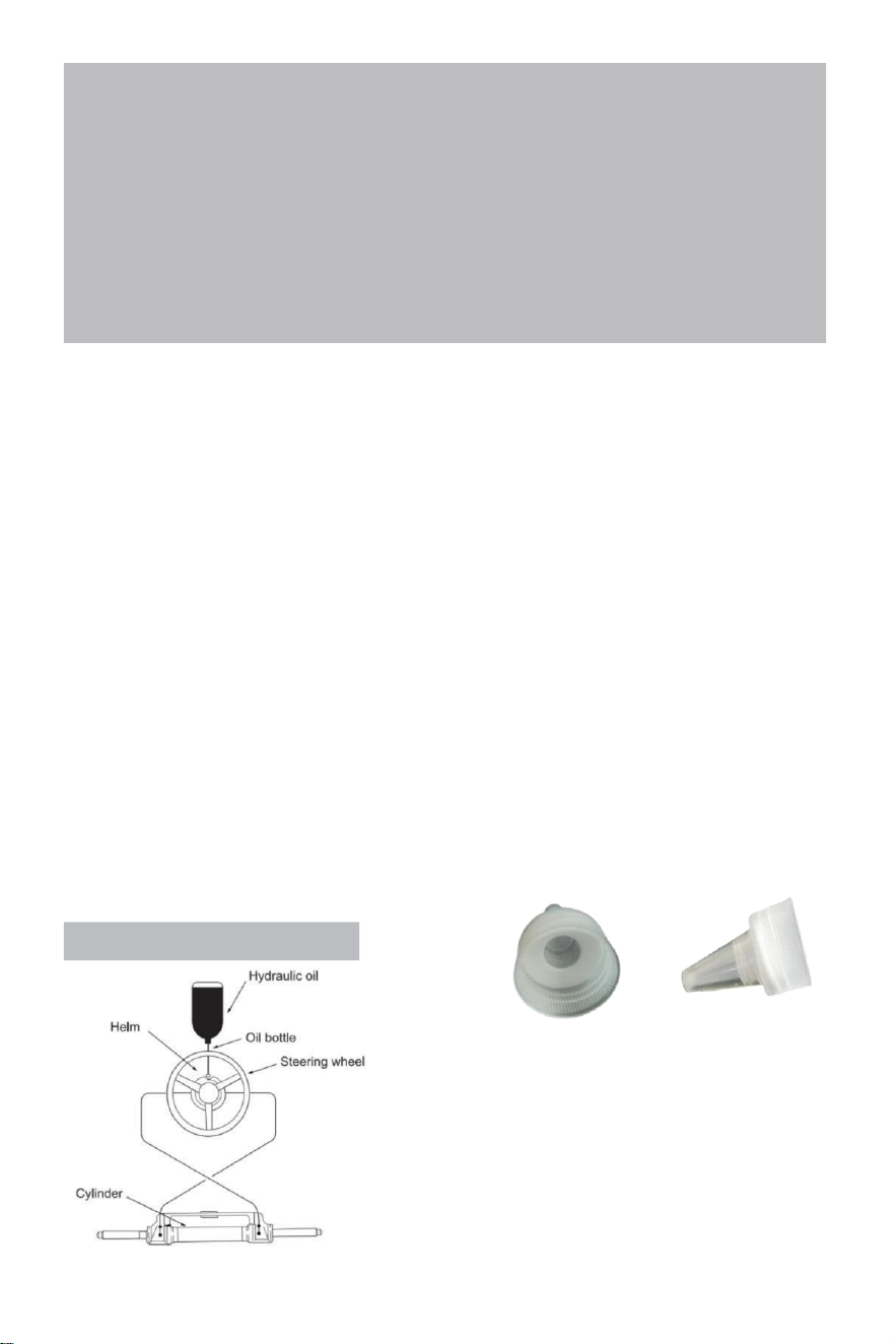
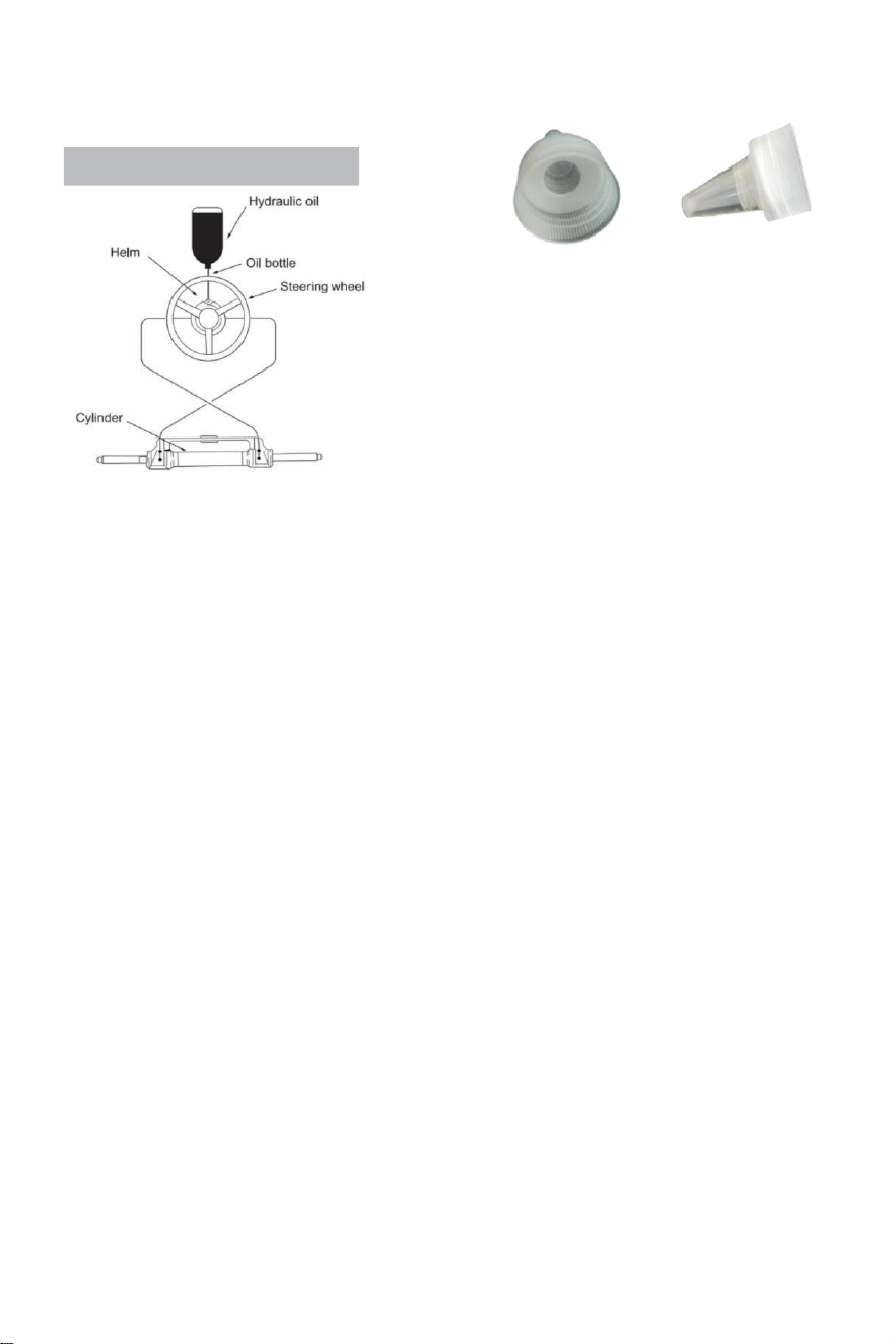
Refueling and Venting Steps:
·Screw the fillet pipe thread equipped with the system
into the fueling pump port and tighten to confirm airtight.
·Fit the sharp mount included with this system to the
oil bottle cap.Insert the sharp mouth into the pump
with some force,pour the oil into the fuel filler pipe
until you can't see the air(the bottle can be squeezed
gently to speed up refueling.)
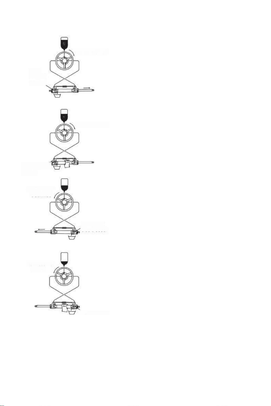
- 15 -
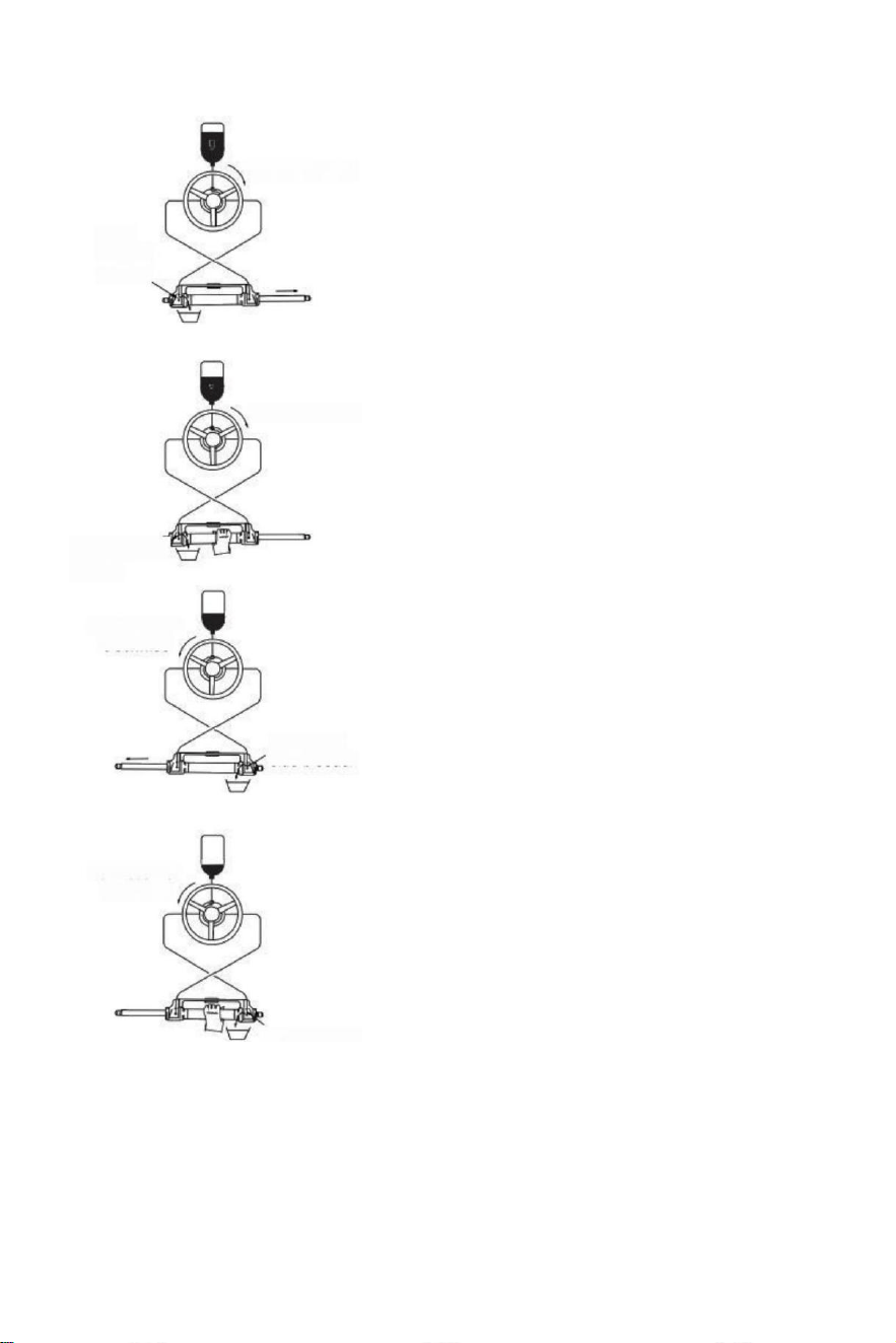
(parameter table)to determine whether the hydraulic
Turn clockwise
Open
left side
bleeder
Turn clockwise
Close left side
bleeder
Turn counter
clockwise
Open right
side bleeder
Turn counter
clockwise
·Turn the steering wheel slowly clockwise
until one side of the piston rod is fully
extended.Fit the exhaust pipe to the
retract side of the piston rod to collect the
oil from venting.
·Hold the cylinder to prevent the cylinder from turning,
unscrew the deflation nipple nested on the
side of the bleeder,(do not unscrew it
completely,it is enough if
you can see the oil)turn the steering wheel
clockwise until you see the inside of the
exhaust pipe Expelled
oil is stable and thorough,no bubbles,turn the
steering wheel at the same time tighten the
deflation nut close exhaust fittings;
·Continue to turn the steering wheel
counterclockwise until the original retraction
side of the piston rod fully extended,Fit the
exhaust pipe to the retract side of the piston
rod to collect the oil from venting
·Hold the cylinder to prevent the cylinder
from turning, unscrew the deflation joint nut
of one side.(Do not unscrew it completely,it
it enough as long as you can see the
oil).Turn the steering wheel clockwise until you
see the oil from the deflating pipe is stable,no
bubbles, tighten the bleeder lock,close
deflation devices.
·Rotate the steering wheel clockwise /counter clockwise
several times to check the number of full helm turns
fluid in the tubing has been completely excluded.If
there is still air,the number of full rudder willincrease.)
if there is still a lot of air that is not excluded,then repeat
procedure(3)~(6). If there is a small amount of air,do
full rudder in one direct,reverse small semi circle,do full
rudder again,do this for 5-6 times for the left direction
and right direction.
·After around rudder test pass,remove the fuel pipe and
bleed pipe,screw the fuel cap,set the deflated connector
sleeve,the unused hydraulic oil is closed for subsequent
maintenance and repair.(Check the hydraulic pump
oil surface once a quarter,insufficient oil will cause
something abnormal.)
Close right side
bleeder

- 16 -
Faults and Solutions:
The following are the most common failures and their causes and solutions.
When the rudder rotates with full rudder(cylinder full stroke),there may be slight
resistance and internal parts click sound which is from internal valve spool ball and bearing
steel ball when they are running.
It is normal phenomena.Please do not think it is caused by faults.
FAULT CAUSE SOLUTION
The hydraulic rudder is
completely stuck during
installation.
Pipe blockage between
the hydraulic pump and
hydraulic cylinder.
Check if the hose pipe is clogged or
bent,if it is bent,you must replace the
damaged hose,or it may result in the
loss of steering and serious personal
injury or property damage.
It is difficult to refuel the
system,even when the
system says the fuel is
full,bubbles continue to
pop out from the oil pump.
·There is air in the system
·Bleed fitting leaks
·Hydraulic pipping has
winding or bending injuries.
.Install the system properly according tothe
installation manual.The inlet pipe must
be always upward.
·Tighten the deflation fittings.
·Unwind and straighten the hose
or replace the damaged hose.
When using the system to
steer,you need to rotate the
full rudder quickly for many
times.
·Hydraulic pipping has
bent injuries
·There is gas or fine bubbles in
the hydraulic oil.
·Incorrect hydraulic oil was used
·Unwind and straighten the
hose or replace the damaged hose.
·Refuel or exhaust properly
according to the installation manual.
·Use the correct hydraulic oil
When the system is full
rudder,the steering
wheel just doesn't work.
There are dirt impurities in
the hydraulic pump
valve
·Do not use the "band"sealing tape at
the interface.
·Take apart the hydraulic pump to
clean the dirt.
The system can steer
the ship easily when the ship
is stationary,However, it is very
difficult to steer while sailing.
·Smallsteering wheel
was selected.
·Engine connection is
not set correctly,
.Airbag is generated in
the system and air is not
excluded completely.
·System configurations
exceed power limits.
·Change to a bigger steering wheel of
which the maximum diameter is
without exceeding 56cm.
·Adjust the engine connection
settings correctly.
·Check the oil surface of hydraulic
pump,reset the refueling and venting
correctly.
Steering wheel turns to
left port side,
Ship turns right
Wrong oil pipe connection
Swap the two oil pipes of the cylinder with
each other and install them.
Cylinder can not be
installed to the engine.
Each cylinder requires
corresponding engine model.
Please refer to the manual or the
customer service of the dealer to
change the model.
When the rudder pump reaches the stop point(cylinder full stroke),a small amount of hydraulic drift is
normal and the rudder pump is not 100%locked.

- 17 -
Maintenance
Warning:
Following the routine maintenance schedules as outlined below,in the time frame noted will ensure
years of service from your VEVOR Steering system as well as keep you and your passengers safe
from the
dangers that are present on and off water.
Failure to comply with maintenance checks may result n loss of steering,causing property
damage and/or personal injury.
Inspections are necessary every year and must be carried out by specialized marine mechanics.
Check the shaft and the o rings of the cylinder,the o rings of the helm pump,the fittings of the
cylinder and helm pump in order to prevent leaks.
Check tightness of all fasteners/fittings throughout the steering system.
Clean the system using fresh water and non-abrasive liquid.
Cleaning fluids containing ammonia,acids or any other corrosive ingredients must not be used
for cleaning any parts of the hydraulic steering system.
DO not use brake oils or automatic transmission fluid(ATE).Use only compatible hydraulic oils.
Prior to every use:
·Check Fluid level in highest helm pump
·Verify immediate steering response when turning steering
wheel(s) (Ensure engine turns when steering wheel is turned).
·Visually inspect all steering hoses and fittings for wear,kinking and /or leaks.
·Check for binding,loose,worn or leaking steering components.
Warning:
DO NOT operate boat if any component is not in proper working condition.
In this case,please take photos immediately and contact your dealer.
After first 20 hours,then every 100 hours or 6 months thereafter(which ever comes first):
·All points noted above
·Check tightness of ALL fasteners/fittings throughout the steering system.Tighten to
correct torque specifications are required.
·Check for mechanical play or slop throughout steering system,correct as required.
·Check for signs of corrosion.If corrosion is present contact your dealer.
After every 200 hours or 12 months(which ever comes first):
·All points noted above.
·Remove support rod from engine steering/tilt tube.Clean engine steering/tilt tube and re-grease
using a good quality marine grease.
·Grease support rod liberally.
·Grease all contact points shown in the cylinder and tie bar installations.
DO NOT remove tiller bolt to re-grease.
·Remove steering wheel and re-grease wheel shaft using a good quality marine grease.
·Inspect hydraulic oil for cleanliness,flush if required.
Any work being performed with the steering system MUST be completed by a qualified mechanic
with the working knowledge of the system.
- 18 -
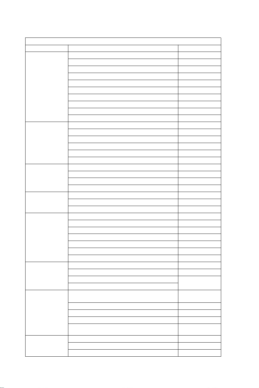
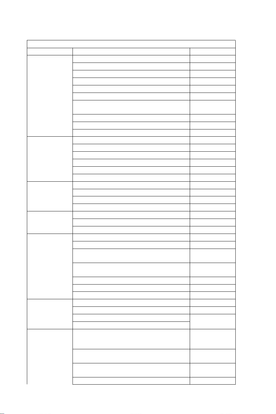
Match the list
HYDRAULIC STEERING SYSTEM UP TO 150HP
ENGINE
POWER
YEAR
Yamaha
60-702 Stroke
1990-2008
75C-902 Stroke
1998-2008
F70 4 Stroke
2010-today
115C-130B 2 Stroke
1990-2008
150F
1996-2007
150 HPDI VMAX 2 Stroke
2000-2008
F75-F80 EFI 4Stroke
1999-2007
F100-F115-F150 EFI 4 Stroke
1999-2007
F80-F100 4 Stroke
2000-today
F115-F150
2004-today
Honda
BF80-BF90 4 Stroke
1995-today
BF115D
1998-2009
BF115A
2009-today
BF130A
1998-2005
BF135-BF1504 Stroke
2005-today
BF90-BF150V-TEC 4 Stroke
2008-today
Suzuki
DF70-80-904 Stroke
1998-today
DF100-115-1404 Stroke"
1998-2008
DF100-115-1404 Stroke new model
2008-today
DF 1504 Stroke
2006-today
Tohatsu
Nissan
70-902 Stroke
2004-today
115-120-1402 Stroke
2004-oday
90-90-115TLD 4 Stroke
2004-2011
Mercury
Mariner
75-90 2 Stroke
1990-2008
115-125-150 EFI 2 Stroke
1990-2007
90-115-125 Optimax 2 Stroke
2004-today
135-150 Optimax 2 Stroke
1999-today
80-90 EFI 4 Stroke
2000-today
100-115 EFI 4 Stroke
2007-today
150 Fourstroke 4 Stroke
2011-today
Evinrude
E50-E55-E602 Stroke
2004-today
E75-E902 Stroke
2004-today
E115-E130-E1352 Stroke V4
1995-today
1995-today
E1502 Stroke V6
Selva
50-Madeira/Bull shark-60 Grey shark/
St.tropez-70 Mako shark 2 Stroke
1996-2008
80 Portofino Tigershark 2 Stroke
1995-2008
150 White shark 2 Stroke
2001-2007
50-60 Dorado EFI 4 Stroke
2001-2007
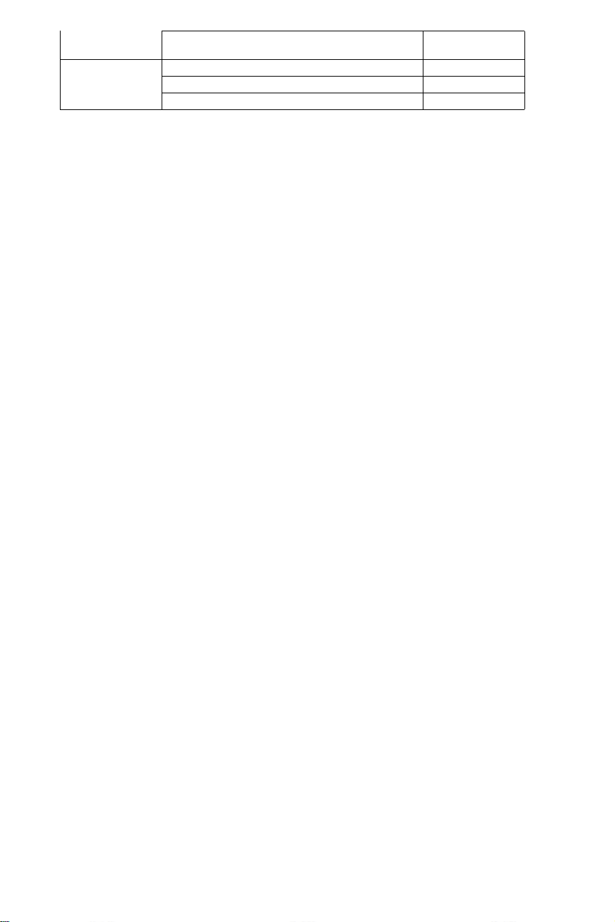
100 EFI Marlin -115 EFINarwhal-150
EFI Killer whale 4 Stroke
2000-today
Johnson
BJ60-704 Stroke
2001-2007
BJ90-115-140 4 Stroke
2001-2007
J90-115V4 2 Stroke
1995-2007
- 19 -
Warning-To reduce the risk of injury, user must read instructions
manual carefully.
Manufacturer: Shanghaimuxinmuyeyouxiangongsi
Address: Shuangchenglu 803nong11hao1602A-1609shi,
baoshanqu,shanghai 200000 CN.
Imported to AUS: SIHAO PTY LTD. 1 ROKEVA
STREETEASTWOODNSW 2122 Australia
Imported to USA: Sanven Technology Ltd. Suite 250, 9166
AnaheimPlace, Rancho Cucamonga, CA 91730
REP
UK
YH CONSULTING LIMITED. C/O YH Consulting
Limited Office 147, Centurion House, London
Road, Staines-upon-Thames, Surrey, TW18 4AX
REP
EC
E-CrossStu GmbH
Mainzer Landstr.69,
60329 Frankfurt am Main.

- 20 -
direction hydraulique Pour les
bateaux
Modèle : YSH -150 CV
- 1 -
direction
hydrauliq
ue Pour
Bateaux
Modèle : YSH -150 CV
C'est l'original instruction, s'il vous plaît lisez tout manuel instructions
attentivement avant toute utilisation. VEVOR se réserve le droit
interprétation de notre manuel d'utilisation. L'apparence du produit
doit être sujet au produit que vous reçu . Veuillez nous excuser de
ne plus vous informer s'il existe une technologie ou un logiciel mises
à jour sur notre produit.
- 2 -
Merci d'avoir acheté le système de direction hydraulique VEVOR.
Ce manuel détaillera les différentes fonctions de ce système afin que vous peut Profitez
pleinement du plaisir haut de gamme que ce produit peut vous apporter.
VEVOR hydraulique pilotage le système est basé sur le concept de industriel moderne
conception, la haut efficacité, haute transmission pouvoir piston pompe technologie
est appliqué à le conception et la fabrication de appareil à gouverner de navire, ce
qui rend votre pilotage système plus stable, plus intelligent et plus fiable.
Le principal composants de le pilotage engrenage sont haut force aluminium
alliage et acier inoxydable qui peut être utilisé dans rude conditions marines et
prolonger le
longévité de a p p a r e i l à gouverner .
Le pilotage engrenage volonté soulager toi depuis le lourd et inflexible
mécanique arbre direction, ce qui peut vous sauver les bras endoloris. Cela peut
améliorer le plaisir de conduire une vedette.
Main features:
● La direction pompe est doté d'une structure intérieure compacte et à la mode et
beau apparence .
●La valve de verrouillage intégrée à deux voies élimine le couple de rebond.
● Facile à remplacer l'arbre t joint, convivial conception ;
●arbre de direction avec spécial surface traitement non seulement a force et fiabilité,
mais aussi a le caractéristiques d'usure résistance à la corrosion résistance.
● Haute résistance aluminium alliage coquille et surface traitement processus peut
assurer son usure et résistance à la corrosion et prévenir l'érosion hydrique
efficacement.
● Tuyauterie : nylon haute résistance raccords rapides 1/4 de tuyau effectue l' installation
compact et il est réutilisable .
●Le utiliser de coutume haut -standard hydraulique huile peut améliorer le lubrification
de parties et protection du joint.

- 3 -
Règles générales de sécurité et garantie
manuel d'installation et de maintenance fait partie intégrante une partie de le produit
et doit être entièrement compris par l'utilisateur avant l'installation.
L'installation, la maintenance et le transfert de hydraulique direction système
composants de VEVOR série de les produits doivent être fait par le autorisé et qualifié
professionnel
techniciens.VEVOR série de produits outils le garantie pour deux années s e r v i c e
après-vente , quand en utilisant le produit, s'il y a un question ou problème, veuillez
contacter le revendeur avec le temps.VEVOR va fournir les conseils corrects. VEVOR ne
prendra pas responsable pour les conséquences d’un démontage ou d’un désassemblage
non autorisé.
Sans préjudice de la nature du produit, VEVOR a le droit droits à faire changements
à le description information et illustrations contenu dans ce manuel, VEVOR n'assume
aucune responsabilité pour l e s conséquences néfastes causées par l'adaptation ce
manuel dans n'importe quel autres moyens illégaux ce qui fait l'utilisateur ne peut pas
suivre le
installation standard dans les instructions.
Installation Précautions:
● Utiliser composants fourni par VEVOR uniquement, Le parties s fourni par
le autre les fabricants peuvent cause dangers pour la sécurité et affecter le
pilotage fonction;
●Activé tous les tuyaux connexion fils, seulement scellés tel comme Loctite PST ou
équivalent
un produit d'étanchéité doit être utilisé. Ne pas utiliser (bandage) ou des bandes
d'étanchéité similaires, car cela peut permettre débris entrer le corps de la pompe et cause
le blocage de le tuyau.
●Veuillez utiliser 10# ou 15# spécial huile hydraulique qualifiée et respectueuse de
l'environnement
amical. Utiliser une autre huile (comme de l'huile de frein) à la place peut causer des
dommages irréparables à votre équipement, provoquant une perte de direction fonction et
aucune garantie.
●Le rayon de courbure minimum du le tuyau mesure 1"18 (30 cm). Ne touchez pas le pointu
objets. Continuer à plier, frotter, gratter ou la torsion peut provoquer le tuyau à être
endommagé et rupture due à la pression de direction normale, provoquant ainsi une perte
de pilotage fonction.
●Ne laissez pas tomber le tuyau librement lors de l'utilisation, veuillez utiliser fil ou autre
matériau PVC pour réparer, afin que à éviter tout danger potentiel pour la sécurité.
● Entretien régulier de composants du système et inspection des tuyaux et accessoires
pour porter ou dommage peut prolonger la durée de vie d'utilisation de ton équipement.

- 4 -
Liste de colisage:
UGS
Modèle
Accessoires d'emballage
Haut-
pression
huile tuyau
longueur
YYZXDB150HP0
5UTKJ001V0
YSH-
150 CV
Pompe hydraulique*1
Plaque de montage*1
Manuel
d'instructions*1
Graisseur pot*1
Tubes de remplissage d'huile*2
Connecteur coudé à 135
degrés *2 Bagues de montage
*4
1/4 rondelle*4
1/4-20UNC noix*4
5/8-18UNF *2
5/8 rondelle*2
0
YYZXXTTJ90HPI
VK97001V0
YSH-
90 CV
Pompe hydraulique *1
Vérin de direction
hydraulique *1 Plaque de
montage *1
Connecteurs coudés à 135
degrés *2 Connecteurs rapides
*2
Bagues de montage *4
1/4 rondelle*4
1/4-20UNC noix*4
5/8-18UNF *2
5/8 rondelle*2
Transparent tuyau avec connecteur
*2 Graisse plastique mamelon *1
Manuel d'instructions *1
Graisseur *1
0
YYZXXTTJ90HP
DLO3P001V0
YSH-
90 CV
Pompe hydraulique*1
Vérin de direction
hydraulique*1 Conduites
d'huile haute pression*2
Plaque de montage*1
Coudes à 135
degrés*2
Connecteurs
rapides*2
Bagues de montage*4
1/4 rondelle*4
1/4-20UNC noix*4
5/8-18UNF *2
5/8 rondelle*2
Transparent tuyaux avec
connecteurs*2 Graisse plastique
mamelon e*1
Instructions*1
Graisseur*1
20 pieds
YYZXXTTJ90HP
WYCCR001V0
YSH-
90 CV
24 pieds
YYZXXTTJ150HI
HNTU001V0
YSH-
150 CV
20 pieds
YYZXXTTJ150H
3TSCX001V0
YSH-
150 CV
24 pieds
YYZXXTTJ150H
3E857001V0
YSH-
150 CV
26 pieds
- 5 -
Technique information:
TAPER
YSH-90HP
YSH-150HP
YSH-200HP
YSH-300HP-B
POMPES
NR90
NR150
NR200
NR300
CAPACITÉ CM³
16
18
27
27
Filetage de roue
5/8"-18UNF
PRESSION MAXIMALE
BARRES
69
69
69
69
TOURS DE ROUE
5
5.5
6
7
CYLINDRES
MR90
MR150
MR200
MR300-B
TUBE ID [mm]
25
30
32
35
TIGE ID [mm]
14
16
16
18
FORCE DE
SORTIE/KGF
232
400
470
470
COURSE [mm]
200
198
200
200
VOLUME [cc]
67
101
125
142
APPLICATION
Jusqu'à
90
CV
En haut à 150
CV
En haut à 200
CV
En haut à 300
CV
Dimensions minimales du puits anti-éclaboussures :
Avant de tenter installation, assurez-vous que le puits anti-
éclaboussures de votre
bateau a les éléments suivants mini maman dimensions.
DIMENSIONS MINIMALES DE LA BUSE À
ÉCLABOUSSURES
Nombre des
moteurs
UN
B
C
1
560 mm-21,25"
152 mm-5,98"
152 mm-5,98"
2
1110 mm-
21,55"
152 mm-5,99"
152 mm-5,99"
- 6 -
Installation de tuyaux/raccords - raccordement de
pompe
Se référer à illustrations ci-dessous pour le raccordement correct des tuyaux de barre pompe au
cylindre.
Raccord de tuyau
- 7 -
Raccord de tuyau
Recommande le utiliser de VEVOR pilotage tuyaux seulement.
Toujours essayer à itinéraire le tuyaux via le le plus court chemin dans commande à éviter
n'importe lequel possible perte de puissance.Dans ordre de faire le air saignement de la système
c'est plus facile, c'est suggéré monter les tuyaux
horizontalement avec un inclinaison de à propos 3 cm par mètre;le pompe côté a à être plus
haut que le cylindre côté.
Toujours protéger le tuyaux que avoir à passer à travers un différent compartiment ou
utiliser approprié connecteurs de cloison ou manche s .
Tuyau avoir à être installé dans tel un chemin ils ne le faites pas représenter un obstacle pour
autre composants.
Faire pas retirer protecteur fin couvertures jusqu'à le tuyaux avoir a été acheminé et sont
prêt à être connecté à la pompe de direction , raccord de tuyau ou vérin(s) de direction.
Fournir suffisant tuyau longueurs à permettre pour cylindre mouvement
to ut
au long de le
tournant arc et haut/bas réglages de trim/inclinaison de le moteur(s).
Tout au long de le tuyau installation, assurer le protecteur casquettes rester installé sur le fin
de le tuyaux.
Attention:
Faire pas installer tuyaux dans un zone où ils volonté être exposé à haut chaleur . Extrême
chaleur réduit la pression d'éclatement du tuyau et peut provoquer l'éclatement du tuyau faire
fondre.Faites preuve d'une grande propreté.Faites bien sûr que tuyaux et tuyaux sont
parfaitement faire le ménage et gratuit depuis copeaux.
Note:
Flexible hoses have to be cut by means of a sharp knife;
never use a saw,as fragments of nylon in the hydraulic system cause serious problems.
- 8 -
Installation de flexibles hydrauliques
Après avoir coupé le nylon tuyau, s'adapte au couplage noix et le soutien manche sur le
tuyau (vérifier il est correctement par rapport à la fin de la tuyau).Après le montage de la noix ,
toi avoir à serré par au moyen d'un clé.
Sinon , vous peut monter tuyau flexible en nylon avec raccords récupérables. Faites comme le
illustrations ci-dessous montrer.
Après le installation faire le ménage le à l'intérieur de le tuyaux par soufflant à travers en
utilisant comprimé l' air , afin à éviter n'importe lequel obstructions et à retirer poussière et
débris depuis stockage.Avant le purge d'air il est aussi suggéré à faire un rinçage de le
système . Faire pas utiliser eau .
1 Après avoir coupé, vissez le raccord de tube manche sur le tube ( gaucher) fil de discussion).
2 Huiler le raccord du tube et vis dans la manche.Faites bien sûr que le revêtement interne de
la
dose du tube
ne pas suivre lors du serrage du vis! Assurez-vous également que l'interne
revêtement de le tubes est pas pressé alors que serrage le vis .
3 Vérifier là est Non interne ingérence putting un petit tournevis dans le tube couplage
avant procéder à l'installation du tuyau au gouvernail ou cylindre
- 9 -
Système de direction hydraulique YSH-150HP
Outils d'installation (Pour compléter le l'installation de ce
système , toi besoin des outils suivants) :
. Trou scie avec 3 . 03 " (77 MM )
diamètre · 0 . 354 " (9 MM ) percer peu
· 1 . 181 " (30 MM ) montage clé
· 0 .433 " ( 11 MM ) installation clé
· 0 . 748 " ( 19 MM ) installation clé
· 0 . 669 " ( 17 MM ) installation clé
· 0 .472 " ( 12 MM ) installation clé
· 0 . 945 " (24 MM ) douille clé
Important:
perform the bleeding procedure manually
and with the helm pump inclined no
more of 10(X).
Steering pump YSH-150HP Installation:
·Déterminer l'angle et vous positionner installent sur assurer que le volant fait pas
interférer avec d'autres équipements. Vérifiez qu'il y a encore suffisant espace derrière le
pont tableau de bord(2)pour les raccords et les raccordements de tuyaux.
RIF.
QUANTITÉ
DESCRIPTION
1
1
pompe
2
1
Conseil
3
4
Cale
4
4
Écrou
d'extension
5
4
Verrouillage
noix
- 10 -
·Attacher a1:1 accéder trou montage modèle (inclus avec ce manuel )à le instrument panneau, et
positionner le montage trou en standard avec un coupe-trou.
· Percer un diamètre de 3,03" (77 mm ) trou et percer quatre 0,354 (9 mm ) de diamètre trous
comme montré sur le gabarit de montage.
·Itinéraire le arrangé tubes à travers le milieu 3,03" (77 mm) de diamètre trou et connecter il à
la direction pompe (1)
·Installer le pilotage pompe sur le instrument panneau avec 4 rondelles (3) et 4 soulagement de la
pluie noix(4),4 contre- écrous (5), serrage couple ≤15N.
·Lubrifier le cône section de la arbre.Installer le semi-circulaire clé.Place le pilotage roue dans le
arbre de direction et le volant clé chemin sur le semi-circulaire clé.Place le cale et serrer le pilotage
verrouillage noix . Le serrage couple est ≤20 Newton .
Note:
·The steering pump should be mounted at a tilt angle of X≤20°.If it is exceeded,it
may cause air to enter the duct and affect the steering function.
·Only use self-locking fasteners provided by VEVOR or standard fasteners.Using non-self-
locking fasteners instead may cause the equipment to loosen or separate.
·Do not open the pump cover or filler cap when installing the steering pump to prevent dirt
and chips from entering the pump and causing the steering function.
·Teflon-like ribbon seals can not be used on pipe nipples,which may cause tape chips to enter
the pump body and thus affect the steering function.(The VEVOR series is a pipe thread
sealing technology that does not require the use of other sealing tape seals.)
VALVE PORTS CONNECTION:
Port marqué « C » : connexions au(x) cylindre(s)
Port marqué « DS » : correspondances vers la station supplémentaire ou pilote automatique
- 11 -
Cylinder YSH-150HP Installation:
AVERTISSEMENT:
Il est important à vérifier
périodiquement , à moins
chaque 3 mois (ou tous les
mois pour usages
professionnels), le droite
couple de ce boulon et de
la verrouillage noix.
Le bras du cylindre doit
être attaché à le moteur
taller bras sur la plupart
marques
de moteurs hors-bord en cas
que le taller interfère avec
d'autres parties de la hors-
bord, alors ça peut être
monté sous la barre plutôt.
AVERTISSEMENT:
Retirez les bouchons rouges
dans l'ordre à installer le
tuyau accessoires .
RIF .
QUANTITÉ
DESCRIPTION
1
1
Cylindre
2
1
Un soutien adéquat
supports
3
1
Soutien de la gauche
supports
4
1
De liaison noix
5
1
Inoxydable boucle en acier
(C)
6
2
Tige de piston
verrouillage noix
·Avant en essayant à installer, s'il vous plaît vérifiez si votre le moteur est approprié pour
ce type du cylindre , et assurer que ton arrière conseil espace est de suffisant taille
pour installation .
· Avant installation , s'il vous plaît lubrifier le mobile connexion parties de le moteur et
le cylindre
et le piston tige avec des marins qualifiés lubrifiant , et redresser ton moteur à le milieu
position;
RIF.
QUANTITY
DESCRIPTION
7
1
3/8 connecting bolt
8
1
3/8 Lock nut
9
2
Deflation device
10
1
Engine connecting block
11
1
Engine mounting hole
- 12 -
·
Desserrer le système autobloquant écrou (6) à
une extrémité de la cylindre piston tige, et retirer
le installation tige (3).Après suppression le
pièces, installer le
installation tige (3)dans le moteur installation
trou (comme montré dans la figure au-dessus
de);
Retirez le boulon (7) du milieu trou de la
cylindrique triangle support support, ajuster
l'Angle du moteur et fixer le cylindre triangle
support à le moteur avec boulon (7) et
noix(8)
correspondant à le trou sur la plaque de
connexion du moteur. Faites attention à le swing
gauche et droit de le machine à assurer que le
cylindre volonté pas interférer avec le
mouvement de le moteur après installation.
Ajuster le moteur Angle et cylindre piston tige
extension longueur.Selon à le écart entre le
moteur et le cylindre correctement installer le
inoxydable acier Serre-joint en C (5) dans le
approprié rainure du montage tige. (Voir
chiffre au-dessus de)
6
3
4
5
7
8
5
- 13 -
Après l'installation, l'écrou de blocage (4) doit être
resserré à éliminer le en fonctionnement
autorisation du cylindre. Cela améliorera votre
expérience.
4

- 14 -
· Après le installation est terminer , pousser ton moteur à le gauche et droite à faire un procès
courir du cylindre. Vérifiez s'il y a des pièces d'interférence lorsque le cylindre fonctionne aller et
retour . Si là est interférence , vous besoin à réadapter le installation . Si là est Non
interférence , pousser le moteur à le fin de le gauche / droite limite . Le suivant étape est
à ravitailler et l'échappement;
· Connecter le arrangé huile tuyaux à le huile tuyau articulations (2) dans séquence , verrouillage
le saigner
joints(3)du cylindre préparer pour le prochain ravitaillement et épuisant mesures pour
l'installation le système.
Warning:
When installing,to avoid bumping the piston rod,it is forbidden to hit the piston rod with wrench or
anything hard.If the piston rod is bruised,it will cause hydraulic oil leakage of the oil cylinder,
which will compromise your product experience.
Direction hydraulique VEVOR delesystème deéchappement
des gaz :
Ce la procédure de travail nécessite deux les gens à exploiter, un personne peut pas être
capable de supprimer complètement tous le air à l'intérieur le hydraulique système lequel
résultats dans que le hydraulique sortie du système pression est pas assez, l'impact de la
faiblesse que nous ressentons, la réponse lente, donc
affectant votre expérience produit.
Veuillez utiliser des moyens spéciaux huile hydraulique écologique fournie par VEVOR ou autre
spécial qualifié
hydraulique huile pour le ravitaillement. Ne pas utiliser huile de frein.Utilisation autres produits
corrosifs inacceptables l'huile peut cause dommages irréparables à votre système et résultat
dans le produit être incapable à être
garanti.

- 15 -
Precautions:
·If you fill the pump with hydraulic fluid before connecting the filler tube to the pump,the
filling procedure can be made more quickly and easily.
·In case of emergency,any non-toxic,non-corrosive,non-flammable oil can be temporarily
supplied to the system,but the entire system must be thoroughly cleaned afterwards;
·Please keep refueling tube visible during the entire refueling process.Do not allow oil to
enter the pump. Otherwise,air may be introduced to increase refueling time.
·During the process of refueling and exhausting,the hydraulic oil collected from the air
bleeder manifold of the cylinder can be used directly after a few moments.
·Please protect the environment and properly dispose of used oil.The special hydraulic
oil provided by VEVOR system can be reused after being filtered by the filter with the hole
diameter less than or equal to 38um.
Les choses nécessitent une attention particulière
Note 1 Utilisez le spécifié vis c o sité 20 #-32 # de hydraulique huile, faire pas utiliser différent types
de hydraulique huile avec une viscosité différente, d o pas mélange hydraulique huile avec n'importe
lequel inconnu liquide.
Remarque 2 Faire pas utiliser impur huile hydraulique, impur l'huile hydraulique va cause
hydraulique pompe échec et bruit.
Note 3 Ajouter huile hydraulique à la hydraulique pompe à le remplissage spécifié port à éviter
mélange eau ou impuretés. Le huile hydraulique doit être maintenu en état d'huile complet dans le
hydraulique pompe.
Remarque 4 Lors de l'ajout huile hydraulique , cela devrait être filtré avec un filtre écran. Non bien
polluants de plus plus de 5 μm-10 μm peuvent pénétrer dans l'huile pompe, qui volonté cause
parties obstruction, bruit, direction commutation soupape mordre, et faire le huile pompe échouer.
Remarque 5 Il devrait y avoir être Non bulles dans le huile hydraulique, qui va augmenter le bruit de
la hydraulique pompe et cause (cause (inconnu). Bulles d'air doit être déchargé. S'il te plaît se référer
à pages 11 et 12 de la manuel pour le fonctionnement spécifique de l'échappement méthodes
Note 6 Dans le processus de utiliser, il est nécessaire à vérifier régulièrement si là est huile fuite
ge dans le pompe corps, huile tuyau et huile cylindre et traiter avec il dans temps .
Note 7 Volant jouer peut être résolu en postulant pression à le pilotage roue. Le
procédure est le suivant : tourner le volant dans le sens des aiguilles d'une montre pour remplir
verrouillage. Continuer tournant le pilotage roue jusqu'à ce que tu te sentes important résistance.
Puis dévisser le bouchon de remplissage de carburant capuchon et continuer remplissage le
carburant pompe à huile. Serrez le bouchon du réservoir, et le pilotage roue jouer volonté être
éliminé.
Remarque 8 Lors du remplissage de l'huile pompe avec huile, s'il te plaît utiliser le huile
remplissage ajutage fourni par nous, lequel est équipé d'un filtre à huile de 60 mm à filtre
dehors impuretés dans le huile.
- 16 -
Refueling and Venting Steps:
·Visser le filetage du tuyau d' égouttage équipé du système
dans l'orifice de la pompe de ravitaillement et serrez pour assurer l'étanchéité.
·Ajuster la monture pointue inclus avec ceci système à
le huile bouchon de bouteille.Insérer le bouche pointue
dans la pompe
avec un peu de force, versez l'huile dans le tuyau de
remplissage de carburant
jusqu'à ce que tu ne puisses plus voir l'air (le bouteille
peut être pressé doucement à vitesse en haut
ravitaillement.)
- 17 -
(parameter table)to determine whether the hydraulic
Turn clockwise
Open
left side
bleeder
Turn clockwise
Close left side
bleeder
Turn counter
clockwise
Open right
side bleeder
Turn counter
clockwise
·Tourner la direction la roue tourne
lentement dans le sens des aiguilles d'une
montre jusqu'à ce qu'un côté de la piston
tige est entièrement
étendu.Ajuster le tuyau d' échappement à
le rétractation côté de la piston tige à
collecter l'huile depuis ventilation.
·Prise le cylindre à prévenir le cylindre depuis
tournant, dévisser le dégonfler le mamelon n ested
sur le
côté de le purgeur (ne pas dévisser) il
complètement, c'est assez si
toi peut voir le huile)tourner le pilotage
roue dans le sens des aiguilles d'une
montre jusqu'à toi voir le à l'intérieur de la
échappement tuyau Exclu
huile est écurie et complet , non bulles ,
tourner le volant à la même temps serrer le
écrou de dégonflage raccords d'échappement serrés ;
·Continuer à tourner le pilotage roue
dans le sens inverse des aiguilles d'une montre
jusqu'à ce que le rétractation originelle côté
de la tige de piston complètement déployée,
ajustement le échappement tuyau à le
rétracter côté de la piston tige à collecter
le huile depuis ventilation
·Tenez le cylindre pour empêcher le cylindre
de tourner, dévisser l' écrou du joint de
dégonflage d'un côté. (Ne pas dévisser
c'est complètement , c'est ça assez comme
long comme toi peut voir le
huile).Tourner le pilotage tournez la roue dans
le sens des aiguilles d'une montre jusqu'à ce que
vous voir le huile depuis le le tuyau de
dégonflage est stable, non bulles, serrez le
saignement verrouiller, fermer
déflation appareils.
·Tournez le volant dans le sens des aiguilles d'une
montre/dans le sens inverse des aiguilles d'une montre
plusieurs fois à vérifier le nombre de tours de barre
complets
liquide dans le tube a a été complètement exclu.Si
il y a toujours l'air, le nombre de gouvernail complet
augmentera .)
si là est toujours un parcelle d'air qui est pas exclu, alors
répéter
procédure (3)~(6). Si là est un petit montant de air ,
faire
complet gouvernail dans un direct, inverse petit s emi
cercle, fais complet
gouvernail à nouveau, fais ce pour 5-6 fois pour la
direction de gauche
et droite direction.
Close right side
bleeder

- 18 -
·Après autour gouvernail test passer, r
supprimer le carburant tuyau et tuyau de
purge, vis le carburant casquette, ensemble le
dégonflé connecteur manche, la inutilisé
hydraulique huile est fermé pour ultérieur
entretien et réparation. (Vérifiez le système
hydraulique pompe huile surface une
fois par quart, insuffisant huile volonté cause
quelque chose d'anormal.)

- 19 -
Défauts et solutions :
Le suivant sont le la plupart commun échecs et leur causes et solutions .
Quand le gouvernail tourne avec complet gouvernail (cylindre plein accident vasculaire
cérébral ), il y a peut être léger résistance et interne pièces cliquettent un bruit qui est de
valve interne piscine balle et palier acier balle quand ils sont en cours d'exécution.
C'est normale phénomènes. S'il vous plaît faire pas pense il est causé par défauts.
FAUTE CAUSE SOLUTION
L'hydraulique gouvernail
est complètement bloqué
pendant installation.
Tuyau obstruction
entre l'hydraulique
pompe et vérin
hydraulique.
Vérifiez si le tuyau tuyau est bouché ou
plié, si c'est est plié, tu dois
remplacer le tuyau endommagé, ou
il se peut résultat dans le perte de
pilotage et sérieux dommages corporels
ou propriété dommage.
Il est difficile à ravitailler le
système, même quand le
système dit le carburant est
plein, bulles continuer à
populaire dehors depuis le huile
pompe.
·Là est air dans le système
·Saigner convenable fuites
· Hydraulique piquage a
enroulement ou flexion blessure
s.
.Installer lesystème correctement selon au
manueld'installation.Le entrée tuyau
doit être toujours vers le haut.
·Serrer le déflation accessoires.
·Se détendre et redresser le
tuyau ou remplacer le
endommagé tuyau.
Quand en utilisant le
système à diriger, tu as
besoin à tourner le
gouvernail complet
rapidement pour beaucoup
fois.
·Hydraulique piquage a
courbé blessures
·Là est gaz ou bien bulles dans
le hydraulique huile.
· Incorrect hydraulique huile a été
utilisé
·Se détendre et redresser le
tuyau ou remplacer le endommagé
tuyau.
·Ravitailler ou échappement
correctement
selon le manuel d'installation .
·Utiliser le correct hydraulique huile
Quand le système est
complet gouvernail, le
pilotage
roue juste n'a pas travail.
Il y a saleté impuretés dans
le hydraulique pompe
soupape
·Ne pas utiliser le étanchéité par «
bande » ruban adhésif à le interface.
·Prendre à part le hydraulique pompe
à faire le ménage le saleté.
Le le système peut diriger
le bateau facilement quand le
bateau est
stationnaire,Cependant, il est
très difficile à diriger alors
que voile.
·Petit volant était choisi.
·Moteur connexion est
pas ensemble
correctement,
.Airbag est généré dans
le système et air n'est pas
exclu complètement.
·Système configurations
dépasser pouvoir
limites.
·Changer en un plus gros pilotage
roue de lequel le maximum diamètre
est sans dépassement 56cm.
·Ajuster le moteur connexion
paramètres correctement.
·Vérifiez le huile surface de l'hydraulique
pompe, réinitialiser le ravitaillement et
ventilation correctement.
Volant tours à gauche
port côté,
Bateau tourne à droite
Mauvaise huile tuyau connexion
Échangez les deux huile tuyaux de le
cylindre avec l'un l'autre et installer
eux .
Cylindre peut pas être
installé à le moteur.
Chaque cylindre nécessite
correspondant moteur modèle.
Veuillez vous référer à le manuel ou
le service client de le revendeur à
changement le modèle.
Quand le gouvernail pompe atteint le arrêt point(cylindre complet accident vasculaire cérébral),un petit
montant de hydraulique dérive est normale et le gouvernail pompe est pas 100% verrouillé.

- 20 -
Entretien
Avertissement:
Suivant le routine entretien horaires comme décrit ci-dessous, dans le laps de temps volonté
notée assurer années de service de votre système de direction VEVOR ainsi que garder toi et ton
passagers sûr depuis le
dangers présents sur et hors de l'eau.
Échec à se conformer avec entretien chèques peut résultat n perte de direction,
provoquant propriété dommages et/ou personnel blessure.
Des inspections sont nécessaires chaque année et doit être Carrie D dehors par spécialisé
marin mécanique. Vérifier le arbre et le ou anneaux de la cylindre, le ou anneaux de la barre
pompe, la accessoires de la
cylindre et pompe à gouvernail dans ordre de prévenir fuites.
Vérifier étanchéité de tous fixations / raccords tout au long de le pilotage système.
Nettoyez le système en utilisant de l'eau douce et non abrasif liquide.
Nettoyage fluides contenant ammoniac, acides ou n'importe lequel autre corrosif
ingrédients doit pas être utilisé pour nettoyer n'importe quel parties de la hydraulique c pilotage
système.
FAIRE pas utiliser frein huiles ou automatique transmission fluide (ATE).Utilisation seulement
compatible hydraulique huiles.
Avant à chaque utiliser:
· Vérifier Fluide niveau dans le plus élevé barre pompe
·Vérifier immédiatement réponse de la direction quand tournant pilotage
roue(s) (Assurez-vous moteur tours quand pilotage la roue est tourné).
· Visuellement inspecter tous pilotage tuyaux et raccords pour usure , pliure et / ou fuites .
·Vérifiez si les fixations sont lâches ou usées ou fuite de direction composants.
Avertissement:
FAIRE PAS fonctionner bateau le cas échéant composant est pas dans bon fonctionnement
condition .
Dans ce cas, s'il vous plaît prendre photos immédiatement et contact ton revendeur.
Après d'abord 20 heures , puis toutes les 100 heures ou 6 mois par la suite ( qui jamais vient
d'abord ):
· Tous points noté au-dessus de
·Vérifier étanchéité de TOUS fixations /raccords tout au long de le pilotage
système.Resserrer à correct des spécifications de couple sont requises.
·Vérifier pour jeu mécanique ou slop tout au long de pilotage système , correct selon les besoins.
·Vérifier pour signes de corrosion.Si la corrosion est présente contact ton revendeur.
Après chaque 200 heures ou 12 mois ( ce qui jamais vient d'abord ):
· Tous points noté au-dessus de .
·Retirer soutien tige depuis moteur direction/inclinaison tube.Nettoyer moteur direction
/inclinaison tube et regraisser en utilisant un bien qualité marine graisse.
·Tige de support de graisse généreusement.
·Graisse tous contact points montré dans le cylindre et cravate bar installations.
FAIRE PAS retirer le motoculteur boulon à regraisser.
·Retirer volant et regraisser roue arbre en utilisant un bien qualité marine graisse.
·Inspecter l'huile hydraulique pour la propreté, rincer si nécessaire.
Tout travail être réalisé avec le système de direction DOIT être complété par un qualifié
mécanicien avec le travail connaissance de la système.
- 21 -
Correspondre la liste
SYSTÈME DE DIRECTION HYDRAULIQUE JUSQU'À 150 CV
MOTEUR
POUVOIR
ANNÉE
Yamaha
60-702 AVC
1990-2008
75C-902 AVC
1998-2008
F70 4 temps
2010-aujourd'hui
115C-130B 2 Accident vasculaire cérébral
1990-2008
150F
1996-2007
150 HPDI VMAX 2 temps
2000-2008
F75-F80 Moteur 4 temps à injection
électronique
1999-2007
F100-F115-F150 EFI 4 temps
1999-2007
F80-F100 4 temps
2000-aujourd'hui
F115-F150
2004-aujourd'hui
Honda
BF80-BF90 4 temps
1995-aujourd'hui
BF115D
1998-2009
BF115A
2009-aujourd'hui
BF130A
1998-2005
BF135-BF1504 AVC
2005-aujourd'hui
BF90-BF150V-TEC 4 temps
2008-aujourd'hui
Suzuki
DF70-80-904 AVC
1998-aujourd'hui
DF100-115-1404 AVC"
1998-2008
DF100-115-1404 Course neuve modèle
2008-aujourd'hui
DF 1504 AVC
2006-aujourd'hui
Tohatsu
Nissan
70-902 AVC
2004-aujourd'hui
115-120-1402 AVC
2004-aujourd'hui
90-90-115TLD 4 temps
2004-2011
Mercure
Marin
75-90 2 Accident vasculaire cérébral
1990-2008
115-125-150 EFI 2 temps
1990-2007
90-115-125 Optimax 2 Accident vasculaire
cérébral
2004-aujourd'hui
135-150 Optimax 2 Accident vasculaire
cérébral
1999-aujourd'hui
80-90 EFI 4 temps
2000-aujourd'hui
100-115 EFI 4 temps
2007-aujourd'hui
150 Quatre temps
2011-aujourd'hui
Evinrude
Course E50-E55-E602
2004-aujourd'hui
E75-E902 AVC
2004-aujourd'hui
E115-E130-E1352 Course V4
1995-aujourd'hui
1995-aujourd'hui
Moteur V6 E1502
Forêt
50-Madère/Requin taureau-60
Requin gris/ Saint-Tropez-70 Requin
Mako 2 temps
1996-2008
80 Portofino Tigershark 2 Accident vasculaire
cérébral
1995-2008
150 Requin blanc 2 Accident vasculaire
cérébral
2001-2007
50-60 Dorado EFI 4 temps
2001-2007
- 22 -
100 EFI Marlin-115 EFINarwhal-150
EFI Orque 4 temps
2000-aujourd'hui
Johnson
Course BJ60-704
2001-2007
BJ90-115-140 4 temps
2001-2007
J90-115V4 2 temps
1995-2007
- 23 -
Avertissement - Pour réduire la risque de blessure, utilisateur
doit lire instructions Lisez attentivement le manuel.
Fabricant : Shanghaimuxinmuyeyouxiangongsi
Adresse : Shuangchenglu 803nong11hao1602A-1609shi,
baoshanqu, shanghai 200000 CN.
Importé en Australie : SIHAO PTY LTD. 1 ROKEVA STREET,
ASTWOOD, NSW 2122, Australie
Importé aux États-Unis : Sanven Technology Ltd. Suite 250,
9166 AnaheimPlace, Rancho Cucamonga, CA 91730
REP
UK
YH CONSULTING LIMITED. C/O YH Consulting
Limited Office 147, Centurion House, London
Road, Staines-upon-Thames, Surrey, TW18 4AX
REP
EC
E-CrossStu GmbH
Mainzer Landstr.69,
60329 Frankfurt am Main.

- 24 -
Hydraulische Lenkung Für
Boote
Modell : YSH -150 PS
- 1 -
Hydraulische
Lenkung
Für
Boote
Modell : YSH -150 PS
Dies ist das Original Anweisung, bitte alles lesen Handbuch
Anweisungen
sorgfältig vor der Inbetriebnahme. VEVOR behält sich das Recht vor,
Interpretation unserer Bedienungsanleitung. Das Aussehen des
Produkts soll Sei Thema zu dem Produkt, das Sie erhalten . Bitte
entschuldigen Sie, dass wir Sie nicht erneut informieren, wenn es
technische oder Software- Probleme gibt. Updates zu unserem
Produkt.
- 2 -
Vielen Dank, dass Sie sich für das hydraulische Lenksystem von VEVOR entschieden haben.
Dieses Handbuch erläutert die verschiedenen Funktionen dieses Systems, so dass Sie
dürfen Erleben Sie den Premium-Genuss, den Ihnen dieses Produkt bieten kann.
VEVOR Hydraulik Lenkung System basiert An Das Konzept von moderne Industrie
Design, die hoch Effizienz, hohe Übertragung Leistung Kolben Pumpe Technologie
Ist angewandt Zu Die Design und Herstellung von Schiffssteueranlage, die Ihr
Lenkung System stabiler, intelligenter und mehr zuverlässig.
Die wichtigsten Komponenten von Die Lenkung Gang Sind hoch Stärke
Aluminium Legierung Und Edelstahl, der verwendet werden kann in harsch
Meeresbedingungen Und erweitern die
Langlebigkeit von Lenkgetriebe .
Der Lenkung Gang Wille entlasten Du aus Die schwer Und unflexibel
mechanisch Welle Lenkung, die Ihre schmerzenden Arme retten kann. Es kann den
Fahrspaß erhöhen Schnellboot.
Main features:
● Die Lenkung Pumpe ist mit kompakter Innenstruktur und der modischen Und
Schön Aussehen .
●Das eingebaute Zweiwege-Sperrventil eliminiert das Rückpralldrehmoment.
● Einfacher Austausch die Welle Dichtung, benutzerfreundlich Design ;
●Lenkwelle mit besonders Oberfläche Behandlung nicht nur hat Stärke Und
Zuverlässigkeit, aber Auch hat Die Eigenschaften des Verschleißes Widerstand,
Korrosion Widerstand.
● Hochfest Aluminium Legierung Hülse Und Oberfläche Behandlung Verfahren dürfen
sicherstellen seine Abnutzung und Korrosionsbeständigkeit und Wassererosion
verhindern effektiv.
● Rohrleitung: Hochfestes Nylon Schnellkupplungen 1/4-Rohrverschraubungen macht die
Installation kompakt Und es ist wiederverwendbar .
●Der verwenden von Brauch hoch -Standard hydraulisch o il dürfen verbessern Die
Schmierung von Teile Und Dichtungsschutz.

- 3 -
Allgemeine Sicherheitsregeln und Garantie
Dieses Installations- und Wartungshandbuch ist ein integraler Teil von das Produkt
und muss sein vor der Installation vollständig vom Benutzer verstanden werden .
Die Installation, Wartung und Übertragung von hydraulisch Richtung System
Komponenten von VEVOR Serie von Produkte müssen Sei Erledigt von Die autorisiert
Und qualifiziert Professional
Techniker.VEVOR Serie von Produkte implementiert Die Garantie für zwei Jahre
Kundendienst , wenn mithilfe der Produkt, wenn es irgendwelche Bei Fragen oder
Problemen wenden Sie sich bitte an den Händler rechtzeitig.VEVOR wird bieten die c
orrect Anleitung.VEVOR wird nicht nehmen verantwortlich für die Folgen einer unbefugten
Demontage oder Zerlegung.
Ohne Beeinträchtigung der Natur des Produkts hat VEVOR die Rechte Zu machen
Änderungen Zu Die Beschreibung Information Und Illustrationen enthalten In Das
Handbuch, VEVOR übernimmt keine Verantwortung für die negativen Folgen der
Bewältigung dieses Handbuch in irgendeiner andere illegale Mittel was macht der
Benutzer kann nicht folgen Die
Standardinstallationsanweisungen .
Installation Vorsichtsmaßnahmen:
● Verwenden Komponenten bereitgestellt von Nur VEVOR, Das Teile s
geliefert von Die andere Hersteller können Ursache Sicherheitsrisiken Und
beeinflussen Die Lenkung Funktion;
●Ein alle Rohre Verbindung Fäden, nur Dichtungen solch als Loctite PST oder
Äquivalent
Dichtmittel sollte verwendet werden. Nicht verwenden (Banding) oder ähnliche
Dichtungsbänder, da dies Trümmer eintreten der Körper von die Pumpe Und Ursache die
Blockade von das Rohr.
●Bitte verwenden Sie 10# oder 15# Spezial Hydrauliköl, das qualifiziert und umweltverträglich
ist
umweltfreundlich. Verwenden Sie stattdessen ein anderes Öl (z. B. Bremsöl) kann
irreparable Schäden verursachen Zu Ihre Ausrüstung, was zu einem Verlust der Lenkung
führt Funktion und keine Garantie.
●Der minimale Biegeradius der Rohr ist 1"18 (30 cm). Berühren Sie nicht die scharf
Gegenstände. Ständiges Biegen, Reiben, Kratzen oder Verdrehen kann zu das Rohr zu
beschädigt und Bruch durch Zu den normalen Lenkdruck , wodurch ein Verlust der
Lenkung Funktion.
●Das Rohr nicht fallen lassen frei Bitte verwenden Sie bei der Verwendung Draht oder
anderes PVC-Material, um beheben, so Zu Vermeiden Sie potenzielle Sicherheitsrisiken.
● Regelmäßige Wartung von Systemkomponenten und Inspektion von Rohrleitungen Und
Armaturen für tragen oder Schaden kann verlängern die Nutzungsdauer von dein
Ausrüstung.

- 4 -
Packliste:
Artikelnu
mmer
Modell
Verpackungszubehör
Hoch-
Druck
Öl Rohr
Länge
YYZXDB150HP0
5UTKJ001V0
YSH-
150 PS
Hydraulikpumpe * 1
Montageplatte * 1
Bedienungsanleitun
g*1 Öler Topf*1
Ölfüllrohre * 2
135-Grad-Winkelverbinder *2
Montagebuchsen *4
1/4
Unterlegscheibe*4
1/4-20UNC Nüsse*4
5/8-18UNF -Kontermuttern*2
5/8
Unterlegschei
be*2
0
YYZXXTTJ90HPI
VK97001V0
YSH-
90 PS
Hydraulikpumpe *1
Hydraulischer Lenkzylinder
*1 Montageplatte *1
135-Grad-Winkelverbinder *2
Schnellverbinder *2
Montagebuchsen *4
1/4
Unterlegscheibe*4
1/4-20UNC Nüsse*4
5/8-18UNF -Kontermuttern*2
5/8 Unterlegscheibe*2
Transparent Schlauch mit
Anschluss *2 Kunststofffett Nippel
*1
Bedienungsanleitung *1
Öler *1
0
YYZXXTTJ90HP
DLO3P001V0
YSH-
90 PS
Hydraulikpumpe * 1
Hydraulischer
Lenkzylinder*1 Hochdruck-
Ölleitungen*2
Montageplatte * 1
135-Grad-
Kniestücke*2
Schnellverbinder*2
Montagebuchsen*4
1/4
Unterlegscheibe*4
1/4-20UNC Nüsse*4
5/8-18UNF -Kontermuttern*2
5/8
Unterlegschei
be*2
Transparent Schläuche mit
Anschlüssen*2 Kunststofffett Nippel
e*1
20 Fuß
YYZXXTTJ90HP
WYCCR001V0
YSH-
90 PS
24 Fuß
YYZXXTTJ150HI
HNTU001V0
YSH-
150 PS
20 Fuß
YYZXXTTJ150H
3TSCX001V0
YSH-
150 PS
24 Fuß
YYZXXTTJ150H
3E857001V0
YSH-
150 PS
26 Fuß
- 5 -
Anleitung*1
Öler * 1
- 6 -
Technisch Information:
TYP
YSH-90HP
YSH-150HP
YSH-200HP
YSH-300HP-B
PUMPS
NR90
NR150
NR200
NR300
KAPAZITÄT CM³
16
18
27
27
Radgewinde
5/8"-18UNF
MAXIMALER DRUCK
BARREN
69
69
69
69
RADUMDREHUNGEN
5
5.5
6
7
ZYLINDER
MR90
MR150
MR200
MR300-B
ROHR
Innendurchmesser
[mm]
25
30
32
35
STANGE
Innendurchmesser
[mm]
14
16
16
18
AUSGANGSKRAFT/KG
F
232
400
470
470
HUB[mm]
200
198
200
200
VOLUMEN [cm³]
67
101
125
142
ANWENDUNG
Bis
zu 90 PS
Hoch Zu 150
PS
Hoch Zu 200
PS
Hoch Zu 300
PS
Mindestmaße des Spritzwasserbeckens:
Bevor Sie versuchen Installation, stellen Sie sicher, dass der
Spritzwasserbereich Ihres
Boot hat folgendes Mini- Mama Abmessungen.
Mindestmaße des Spritzwasserbeckens
Nummer von
A
B
C
- 7 -
Motors
1
560 mm –
21,25 Zoll
152 mm –
5,98 Zoll
152 mm – 5,98
Zoll
2
1110 mm –
21,55 Zoll
152 mm –
5,99 Zoll
152 mm – 5,99
Zoll
- 8 -
Schläuche/Armaturen Installation-
Pumpenanschluss
Siehe Abbildungen unten für den richtigen Anschluss von Schläuchen von Helm Pumpe zum
Zylinder.
Schlauchanschluss
- 9 -
Schlauchanschluss
Empfiehlt Die verwenden von VEVOR Lenkung Schläuche nur.
Stets versuchen Zu Route Die Schläuche über Die kürzeste Weg In Befehl Zu vermeiden
beliebig möglich Verlust von Macht.In um zu machen Die Luft Blutung von t er System einfacher ist
es empfohlen montieren die Schläuche
horizontal mit ein Neigung von um 3 cm pro Meter;der Pumpe Seite hat Zu Sei höher als Die
Zylinder Seite.
Stets schützen Die Schläuche Das haben Zu passieren durch A anders Fach oder
verwenden geeignet Schottverbinder oder Ärmel .
Schlauch haben Zu Sei installiert In solch A Weg Sie nicht darstellen ein Hindernis für andere
Komponenten.
Tun nicht entfernen schützend Ende Abdeckungen bis Die Schläuche haben gewesen
geroutet Und Sind bereit Zu Sei verbunden Zu die Ruderpumpe p, Schlauchanschluss oder
Lenkzylinder.
Bieten ausreichend Schlauch Längen Zu erlauben für Zylinder Bewegung hindurch Die
Drehen Bogen Und hoch/runter Trimm-/Neigungseinstellungen von Die Motor(en).
Hindurch Die Schlauch Installation, stellen Sie sicher Die schützend Kappen bleiben installiert
auf Die Ende von Die Schläuche.
Aufmerksamkeit:
Tun nicht installieren Schläuche In ein Bereich Wo Sie Wille Sei ausgesetzt Zu hoch Hitze .
Extrem Hitze reduziert den Berstdruck des Schlauches und kann dazu führen, dass der Schlauch
Schmelzen.Üben Sie große Sauberkeit.Machen Sicher Das Rohre und Schläuche Sind perfekt
sauber Und frei aus Späne.
Note:
Flexible hoses have to be cut by means of a sharp knife;
never use a saw,as fragments of nylon in the hydraulic system cause serious problems.
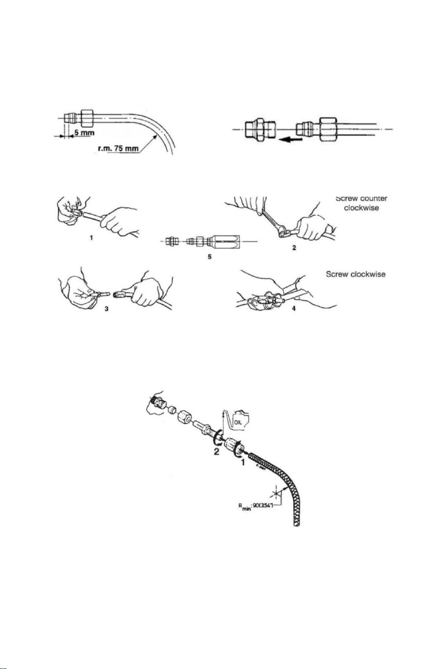
- 10 -
Installation von Hydraulikschläuchen
Nach dem Schneiden des Nylons Schlauch, passen Sie die Kupplung Nuss und Die
Unterstützung Ärmel An den Schlauch (überprüfen Es ist richtig in Bezug auf die Ende der
Schlauch).Nach dem Montage der Nuss , du haben Zu eng von mittels einer Schlüssel.
Ansonsten , Sie dürfen montieren flexibler Nylonschlauch mit wiederverwendbaren Armaturen .
Machen Sie es wie Abbildungen unten zeigen.
Nach Die Installation sauber Die innen von Die Schläuche von Blasen durch mit
komprimiert Luft , um Zu vermeiden beliebig Hindernisse Und Zu entfernen Staub Und
Trümmer aus Lagerung.Vorher Die Entlüftung Es Ist Auch empfohlen Zu machen A
Spülung von Die System . Tun nicht verwenden Wasser .
1 Nach dem Schneiden die Rohrkupplung Ärmel auf der Schlauch ( linkshändig Faden).
2 Ölen Sie die Rohrkupplung Und schrauben es in die Hülse. Machen Sicher Das die innere
Ummantelung von
die Schlauchdosis
nicht folgen, während Sie die Schraube!Achten Sie auch darauf
Das das Innere
Ummantelung von Die Schläuche Ist nicht gequetscht während Anziehen Die schrauben .
3 Prüfen Dort Ist NEIN intern Interferenz Putten A klein Schraubendreher hinein Die Rohr
Kupplung vor Fahren Sie mit der Schlauchinstallation fort, um zu steuern oder Zylinder
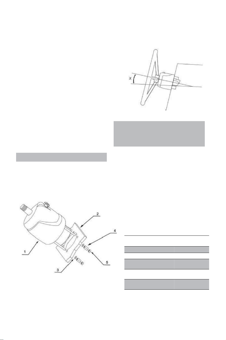
- 11 -
Hydraulisches Lenksystem YSH-150HP
Installationstools (Um die Installation dieses Systems , Du
benötigen Sie folgende Werkzeuge):
. Loch gesehen mit 3 . 03 " (77 MM )
Durchmesser · 0 . 354 " (9 MM ) bohren
bisschen
· 1 . 181 " (30 MM ) Montage Schlüssel
· 0 .433 " ( 11 MM ) Installation Schlüssel
· 0 . 748 " ( 19 MM ) Installation Schlüssel
· 0 . 669 " ( 17 MM ) Installation Schlüssel
· 0 .472 " ( 12 MM ) Installation Schlüssel
· 0 . 945 " (24 MM ) Buchse Schlüssel
Important:
perform the bleeding procedure manually
and with the helm pump inclined no
more of 10(X).
Steering pump YSH-150HP Installation:
·Bestimmen Sie den Winkel und positionieren Sie installieren auf sicherstellen Das Die
Lenkrad tut nicht stören mit anderen Geräten. Überprüfen Sie, ob noch ausreichend Raum
hinter Die Brücke Armaturenbrett (2) für Armaturen- und Rohrverbindungen.
RIF.
MENGE
BESCHREIBUN
G
1
1
Pumpe
2
1
Planke
3
4
Unterlegsc
heibe
4
4
Verlängerungs
mutter
5
4
Sperren
Nuss
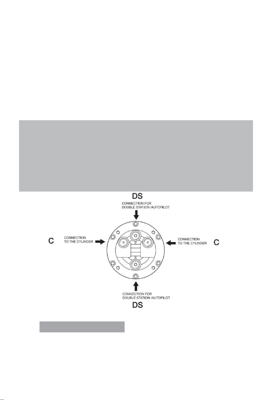
- 12 -
·Befestigen a1:1 Zugang Loch Montage Vorlage (im Lieferumfang enthalten) mit Das Handbuch )
zu Die Instrument Panel und Positionieren Sie die Montage Loch als Standard mit einem
Lochschneider.
· Bohren einen Durchmesser von 3,03" (77 mm ) Loch Und bohren vier 0,354 (9 mm )
Durchmesser Löcher als gezeigt An der Montageschablone.
·Route Die arrangiert Schläuche durch Die Mitte 3,03" (77 mm) Durchmesser Loch Und
verbinden Es Zu die Lenkung Pumpe (1)
·Installieren Die Lenkung Pumpe An Die Instrument Panel mit 4 Unterlegscheiben (3) und 4
Regenhilfe Nüsse(4),4 Kontermuttern (5) , Anziehen Drehmoment ≤15N.
·Schmieren Die Verjüngung Abschnitt der Welle.Installieren Die halbkreisförmig Schlüssel.Ort Die
Lenkung Rad In Die Richtungswelle und das Lenkrad Schlüssel Weg auf Die halbkreisförmig
Schlüssel.Ort Die Unterlegscheibe Und festziehen Lenkung sperren Nuss . Die Anziehen
Drehmoment Ist ≤20 Newton .
Note:
·The steering pump should be mounted at a tilt angle of X≤20°.If it is exceeded,it
may cause air to enter the duct and affect the steering function.
·Only use self-locking fasteners provided by VEVOR or standard fasteners.Using non-self-
locking fasteners instead may cause the equipment to loosen or separate.
·Do not open the pump cover or filler cap when installing the steering pump to prevent dirt
and chips from entering the pump and causing the steering function.
·Teflon-like ribbon seals can not be used on pipe nipples,which may cause tape chips to enter
the pump body and thus affect the steering function.(The VEVOR series is a pipe thread
sealing technology that does not require the use of other sealing tape seals.)
VALVE PORTS CONNECTION:
Anschluss mit der Markierung „C“: Verbindungen zu den Zylindern
Hafen mit „DS“ gekennzeichnet: Verbindungen zur Zusatzstation oder Autopilot
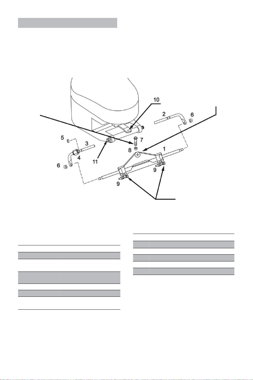
- 13 -
Cylinder YSH-150HP Installation:
WARNUNG:
Es Ist wichtig Zu überprüfen
regelmäßig , bei am
wenigsten jeder 3 Monate
(oder jeden Monat für
professionelle
Anwendungen), die
Rechts Drehmoment
dieser Schraube Und der
sperren Nuss.
Der Zylinderarm sollte
angebracht sein von Die
Motor Pinne Arm auf den
meisten Marken
von Außenbordmotoren im
Event Das Die Pinne
stört mit andere Teile der
Außenborder, Dann es kann
Sei montiert unter der Pinne
stattdessen.
WARNUNG:
Entfernen Sie die roten
Kappen der Reihe nach Zu
installieren Die Schläuche
Armaturen .
RIF .
MENGE
BESCHREIBUNG
1
1
Zylinder
2
1
Richtige Unterstützung
Klammern
3
1
Linke Unterstützung
Klammern
4
1
Verbinden Nuss
5
1
Edelstahl Stahlschnalle (C )
6
2
Kolbenstange
Verriegelung Nuss
·Vor versuchen Zu installieren, bitte prüfen Sie, ob Ihr Motor ist geeignet für diesen Typ
des Zylinders und sicherstellen Das dein Stern Planke Raum Ist von ausreichend
Größe für Installation .
· Vorher Installation , bitte schmieren Die beweglich Verbindung Teile von Die Motor Und
der Zylinder
Und Die Kolben Stange mit qualifiziertem Marine Schmiermittel und begradigen dein Motor Zu
die Mitte Position;
RIF.
QUANTITY
DESCRIPTION
7
1
3/8 connecting bolt
8
1
3/8 Lock nut
9
2
Deflation device
10
1
Engine connecting block
11
1
Engine mounting hole
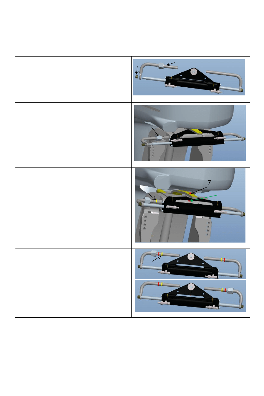
- 14 -
·
Lösen Sie die Selbsthemmung Mutter (6) an
einem Ende der Zylinder Kolben Stange und
entfernen Die Installation Stange (3).Nach
Entfernen Die Teile, installieren Sie die
Installation Stange (3)in Die Motor Installation
Loch (als in der Abbildung gezeigt über);
Entfernen Sie die Schraube (7) aus der Mitte
Loch der zylindrisch Dreieck Halterung
Halterung, einstellen der Winkel des Motors und
befestigen Sie den Zylinder Dreieck Halterung
Zu Die Motor mit Bolzen(7) und Nuss(8)
entsprechend Zu das Loch auf der
Motoranschlussplatte. Achten Sie auf der linke
und rechte Schwung von Die Maschine Zu
sicherstellen Das Die Zylinder Wille nicht stören
mit Die Bewegung von Die Motor nach
Installation.
Anpassen Die Motor Winkel Und Zylinder
Kolben Stange Verlängerung Länge.Laut Zu
Die Lücke zwischen den Motor und Zylinder
richtig installieren Sie die Edelstahl Stahl C-
Klemme(5) in Die geeignet Rille der Montage
Stange. (Siehe Figur über)
6
3
4
5
7
8
5
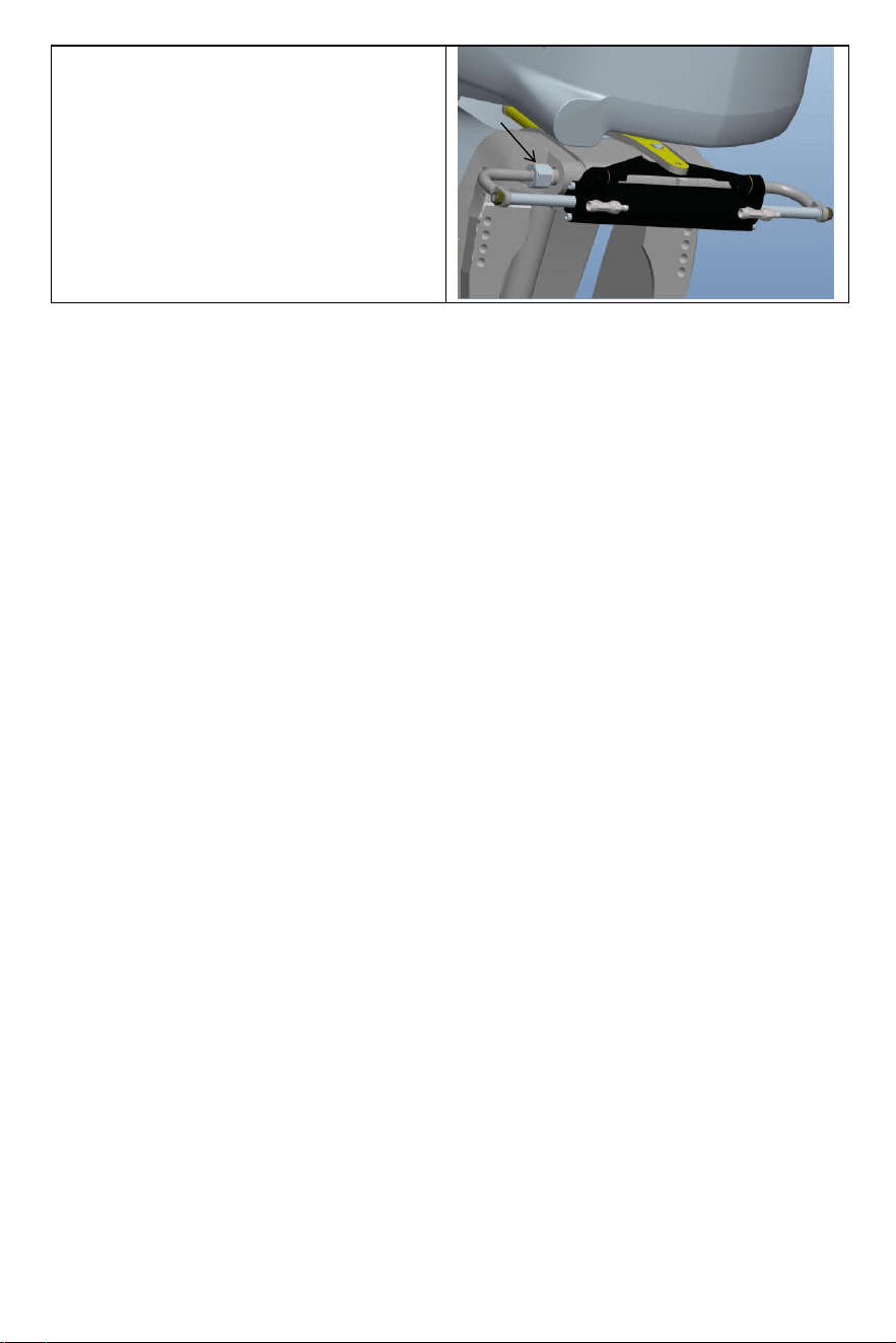
- 15 -
Nach der Montage sollte die Kontermutter (4)
verschärft Zu eliminieren Die Betriebs
Spielraum des Zylinders. Dies wird Ihr Erlebnis
verbessern.
4

- 16 -
· Nach Die Installation Ist komplett , drücken dein Motor Zu Die links Und Rechts Zu machen A
Versuch laufen des Zylinders. Prüfen Sie, ob es Störteile gibt, wenn der Zylinder läuft hin und her .
Wenn Dort Ist Störungen , Sie brauchen Zu neu einstellen Die Installation . Wenn Dort Ist
NEIN
Störung , Druck Die Motor Zu Die Ende von Die links rechts Grenze . Die nächste Schritt
Ist Zu tanken und Auspuff;
· Verbinden Die arrangiert Öl Rohre Zu Die Öl Rohr Gelenke (2) in Sequenz , Sperre Die bluten
Gelenke (3) des Zylinders vorbereiten für der nächste Betankung Und anstrengend Schritte
zum Einbau Die System.
Warning:
When installing,to avoid bumping the piston rod,it is forbidden to hit the piston rod with wrench or
anything hard.If the piston rod is bruised,it will cause hydraulic oil leakage of the oil cylinder,
which will compromise your product experience.
VEVOR hydraulische Richtung Die System der Abgase:
Das Arbeitsablauf erfordert zwei Menschen zu bedienen, eine Person Mai nicht Sei in der Lage
vollständig entfernen alle Die Luft innen Die hydraulisch System welche Ergebnisse In Das
Die hydraulisch Systemausgabe Druck Ist nicht genug, die Auswirkungen der Schwäche wir
erkennen, langsame Reaktion, so
Auswirkungen auf Ihr Produkterlebnis.
Bitte verwenden Sie spezielle umweltfreundliches Hydrauliköl von VEVOR oder andere qualifizierte
Spezial
hydraulisch Öl zum Tanken. Nicht verwenden Bremsöl.Verwenden andere nicht akzeptable
ätzende Öl kann Ursache irreparable Schäden an Ihrem System Und Ergebnis im Produkt
Sein nicht in der Lage Zu Sei
garantiert.

- 17 -
Precautions:
·If you fill the pump with hydraulic fluid before connecting the filler tube to the pump,the
filling procedure can be made more quickly and easily.
·In case of emergency,any non-toxic,non-corrosive,non-flammable oil can be temporarily
supplied to the system,but the entire system must be thoroughly cleaned afterwards;
·Please keep refueling tube visible during the entire refueling process.Do not allow oil to
enter the pump. Otherwise,air may be introduced to increase refueling time.
·During the process of refueling and exhausting,the hydraulic oil collected from the air
bleeder manifold of the cylinder can be used directly after a few moments.
·Please protect the environment and properly dispose of used oil.The special hydraulic
oil provided by VEVOR system can be reused after being filtered by the filter with the hole
diameter less than or equal to 38um.
Angelegenheiten erfordern Aufmerksamkeit
Notiz 1 Verwenden Sie die angegebene 20 #-32# Viskosität von hydraulisch Öl, Tun nicht verwenden
anders Typen von hydraulisch Öl mit unterschiedlicher Viskosität, d o nicht Mischhydraulik Öl mit
beliebig unbekannt flüssig.
Hinweis 2 nicht verwenden unrein Hydrauliköl, unrein Hydrauliköl wird Ursache hydraulisch
Pumpe Versagen Und Lärm.
Hinweis 3 Hinzufügen Hydrauliköl zum hydraulisch Pumpe bei Die spezifizierte Füllung Hafen Zu
vermeiden mischen Wasser oder Verunreinigungen. Die Hydrauliköl muss Sei gepflegt im
Vollölzustand im hydraulisch Pumpe.
Hinweis 4 Beim Hinzufügen Hydrauliköl , es sollte gefiltert werden mit A Filter Bildschirm. NEIN
Bußgeld Schadstoffe von mehr als 5 μm–10 μm können in das Öl gelangen Pumpe, die Wille
Ursache Teile Blockierung, Lärm, Richtung Umschalten Ventil beißen und machen die Öl Pumpe
scheitern.
Hinweis 5 Es sollte Sei NEIN Blasen im Hydrauliköl, das Zunahme Die Lärm der hydraulisch Pumpe
und Ursache (Ursache unbekannt) Fehler. Luftblasen muss Sei entladen. Bitte beziehen sich auf
Seiten 11 Und 12 der Handbuch für den spezifischen Abgasbetrieb Methoden
Anmerkung 6 Im Prozess der verwenden, Es Ist notwendig Zu überprüfen regelmäßig ob Dort Ist
Öl leaka ge In Die Pumpe Körper, Öl Rohr und Öl Zylinder Und bewältigen Es In Zeit .
Hinweis 7 Lenkrad spielen kann Sei gelöst durch die Anwendung Druck Zu Die Lenkung Rad. Der
Verfahren ist wie folgt: Drehen Sie das Lenkrad im Uhrzeigersinn bis zum Anschlag sperren.
Weitermachen Drehen Die Lenkung Rad bis du dich wichtig fühlst Widerstand. Dann Schrauben
Sie den Tankdeckel ab Kappe Und weitermachen Füllung Die Kraftstoff Pumpe mit Öl. Tankdeckel
festziehen, Und Die Lenkung Rad spielen Wille Sei beseitigt.
Hinweis 8 Beim Einfüllen des Öls Pumpe mit Öl, Bitte verwenden Sie die Öl Füllstoff Düse
bereitgestellt von uns, welche Ist ausgestattet mit einem 60-Maschen -Ölfilter Zu Filter aus
Verunreinigungen In Die Öl.
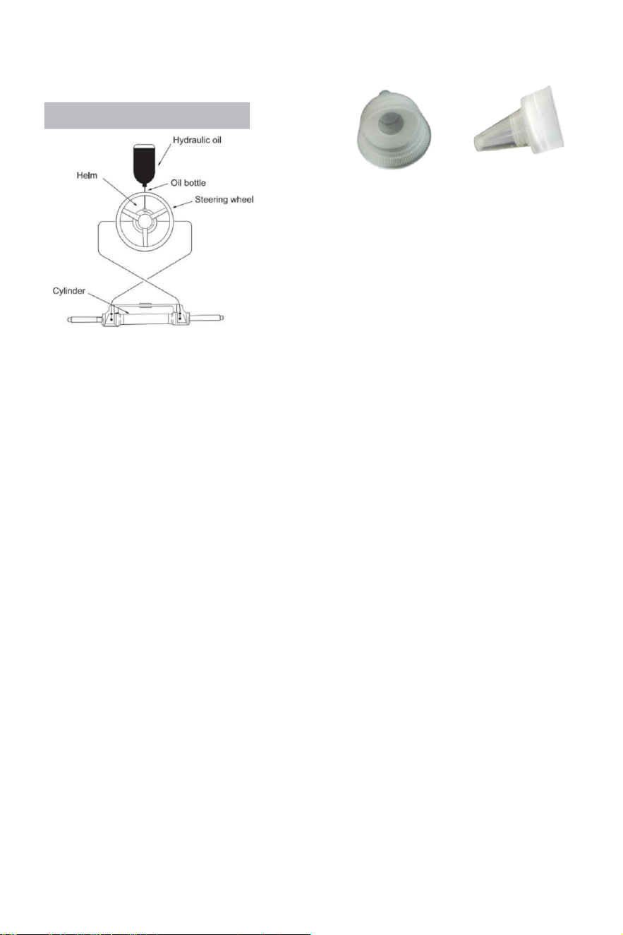
- 18 -
Refueling and Venting Steps:
Sie das Kehlrohrgewinde ausgestattet mit dem System
in den Anschluss der Betankungspumpe und festziehen, um sicherzustellen, dass es luftdicht ist.
·Fit die scharfe Halterung im Lieferumfang enthalten
System Zu Die Öl Flaschenverschluss.Einfügen Die
scharfen Mund in die Pumpe
Gießen Sie das Öl mit etwas Kraft in das Einfüllrohr des
Kraftstoffs
bis man die Luft nicht mehr sehen kann (die Flasche
dürfen gequetscht werden sanft Zu Geschwindigkeit
hoch Tanken.)
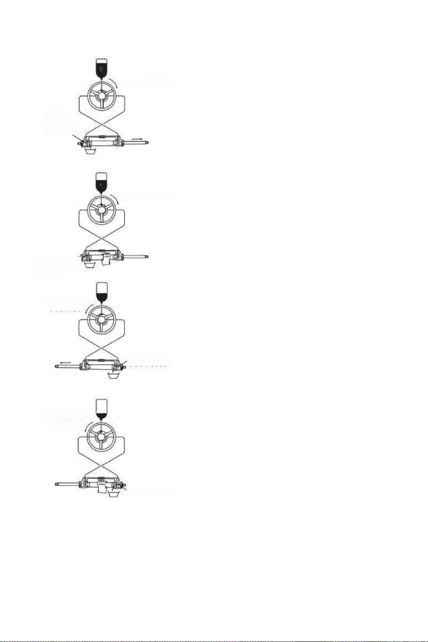
- 19 -
(parameter table)to determine whether the hydraulic
Turn clockwise
Open
left side
bleeder
Turn clockwise
Close left side
bleeder
Turn counter
clockwise
Open right
side bleeder
Turn counter
clockwise
·Drehen die Lenkung Rad langsam im
Uhrzeigersinn bis eine Seite des Kolben
Stange ist vollständig
erweitert.Passen Sie die Auspuffrohr
Zu der Rückzug Seite der Kolben Stange
Zu sammeln das Öl aus Entlüftung.
·Halten Die Zylinder Zu verhindern Die Zylinder aus
Drehen, abschrauben Die entleeren i auf Brustwarze
n ested An Die
Seite von den Entlüfter (nicht
abschrauben Es vollständig, es ist
genug, wenn
Du dürfen sehen Die Öl)drehen Die
Lenkung Rad im Uhrzeigersinn, bis Du
sehen Die innen von t er
Auspuff Rohr Ausgewiesen
Öl Ist stabil Und gründlich , nein Blasen ,
drehen das Lenkrad an der Dasselbe Zeit
anziehen Die
Entlüftungsmutter Auspuffanschlüsse schließen ;
·Weitermachen Zu drehen Die Lenkung Rad
gegen den Uhrzeigersinn, bis die
ursprüngliche Retraktion Seite von die
Kolbenstange vollständig ausgefahren,Fit Die
ex h aust Rohr Zu Die einfahren Seite e der
Kolben Stange Zu sammeln Die Öl aus
Entlüftung
·Halten Sie den Zylinder zu verhindern Die Zylinder
vom Drehen, Schraube n Sie die Mutter des
Entlüftungsgelenks ab von einem Seite. (Nicht
abschrauben es ist völlig, es ist genug als lang
als Du dürfen sehen Die
Öl).Drehen Die Lenkung Rad im Uhrzeigersinn,
bis Sie sehen Die Öl aus Die Entleerungsrohr
ist stabil, keine Blasen, ziehen Sie die Bluter
sperren, schließen
Deflation Geräte.
·Drehen Sie das Lenkrad im Uhrzeigersinn/gegen den
Uhrzeigersinn
mehrere mal Zu überprüfen die Nummer von volle
Ruderdrehungen
Flüssigkeit im Schlauch hat gewesen vollständig
ausgeschlossen.Wenn
Es gibt Trotzdem Luft, die Zahl von Vollruder wird
zunehmen.)
Wenn Dort Ist Trotzdem A viel von Luft, die Ist nicht
ausgeschlossen, dann wiederholen
Verfahren (3)~(6). Wenn Dort Ist A klein Menge von
Luft , tun
voll Ruder In eins direkt, umgekehrt klein s emi Kreis,
tun voll
Ruder wieder, tun Das für 5-6 mal für die linke Richtung
Und Rechts Richtung.
Close right side
bleeder

- 20 -
·Nach um Ruder prüfen Passieren, Entfernen
Die Kraftstoff Rohr Und Entlüftungsrohr,
Schraube der Kraftstoff Kappe, Satz Die
entleert Anschluss Ärmel, die ungenutzt
hydraulisch Öl Ist geschlossen für
nachfolgende Wartung und Reparatur.
(Überprüfen Sie die Hydraulik pu m p Öl
Oberfläche einmal ein Viertel,unzureichend
Öl Wille Ursache
etwas Ungewöhnliches.)

- 21 -
Störungen und Lösungen:
Der folgende Sind Die am meisten gemeinsam Fehler Und ihre Ursachen Und Lösungen .
Wann Die Ruder dreht sich mit voll Ruder (Zylinder voll Schlaganfall ), gibt es Vielleicht
leicht Widerstand Und intern Teile klicken Geräusch, das ist von Innenventil s Pool Ball
Und Lager Stahl Ball wenn sie Sind läuft.
Es ist Normal Phänomene. Bitte Tun nicht denken Es Ist verursacht von Fehler.
FEHLER URSACHE LÖSUNG
Die hydraulische Ruder
Ist vollständig gesteckt
während Installation.
Rohr Blockierung
zwischen die
hydraulische Pumpe
Und Hydraulikzylinder.
Überprüfen Sie, ob Die Schlauch Rohr Ist
verstopft oder gebogen, wenn es Ist
gebogen, müssen Sie ersetzen der
beschädigte Schlauch, oder es kann
Ergebnis im Verlust von Lenkung Und
ernst Personenschäden oder Eigentum
Schaden.
Es ist schwierig Zu tanken
Die System, sogar Wann
Die
System sagt Die Kraftstoff Ist
voll, Blasen weitermachen Zu
Pop aus aus Die Öl Pumpe.
·Dort Ist Luft In Die System
·Bluten Beschlag Lecks
·Hydrau l ik Piping hat
Wicklung oder Biegen
Verletzung s.
.Installieren Sie das System richtig nach
zum Installationshandbuch.Die Einlass
Rohr muss Sei stets nach oben.
·Anziehen Die Deflation Armaturen.
·Entspannen Und gerade ich
glätten Die Schlauch oder
ersetzen Die beschädigt
Schlauch.
Wann mit Die System Zu
steuern, Sie brauchen Zu
drehen das volle Ruder
schnell für viele mal.
·Hydraulisch Piping hat
gebogen Verletzungen
·Dort Ist Gas oder Bußgeld
Blasen In Die hydraulisch Öl.
· Falsche Hydraulik Öl war uns ed
·Entspannen Und begradigen Die
Schlauch oder ersetzen Die beschädigt
Schlauch.
·Tanken oder Auspuff richtig
entsprechend der Installationshandbuch .
·Verwenden Die richtig Hydraulik o
ich l
Wann Die System Ist voll
Ruder, das Lenkung
Rad Nur nicht arbeiten.
Es gibt Schmutz
Verunreinigungen In Die
hydraulisch Pumpe
Ventil
·Nicht verwenden Die "Band"-
Versiegelung Band bei Die
Schnittstelle.
·Nehmen auseinander Die hydraulisch
Pumpe Zu sauber Die Schmutz.
Der System kann steuern
Die Schiff leicht, wenn Die
Schiff Ist stationär,jedoch Es
ist sehr schwierig Zu
steuern während Segeln.
·Kleines Lenkrad War
ausgewählt.
·Motor Verbindung Ist
nicht Satz korrekt,
.Airbag Ist generiert In
Die System Und Luft ist
nicht ausgeschlossen
vollständig.
·System Konfigurationen
überschreiten Leistung
Grenzen.
·Ändern zu A größer Lenkung Rad
von welche Die maximal
Durchmesser Ist ohne
Überschreitung 56 cm.
·Anpassen Die Motor
Verbindung Einstellungen
korrekt.
·Überprüfen Sie die Öl Oberfläche der
hydraulischen Pumpe, setzen Sie die
Betankung zurück und Entlüftung
korrekt.
Lenkrad dreht sich Zu
links Hafen Seite,
Schiff biegt rechts ab
Falsches Öl Rohr Verbindung
TauschenSiedie beiden Öl Rohre von Die
Zylinder mit gegenseitig Und
installieren ihnen .
Zylinder kann nicht Sei
installiert Zu Die Motor.
Jede Zylinder erfordert
entsprechend Motor Modell.
Bitte beachten Sie Die Handbuch
oder Die Kundendienst von Die
Händler Zu ändern Die Modell.
Wann Die Ruder Pumpe erreicht Die stoppen Punkt (Zylinder voll Schlaganfall), ein klein Menge von
Hydraulik Drift Ist Normal Und Die Ruder Pumpe Ist nicht 100 % gesperrt.

- 22 -
Wartung
Warnung:
Gefolgt Die Routine Wartung Zeitpläne als umrissen unten, in Die Zeitrahmen bemerkt wird
sicherstellen Jahre Service von Ihrem VEVOR Lenksystem sowie halten Du Und dein Passagiere
sicher aus Die
Gefahren, die vorhanden sind An Und aus dem Wasser.
Versagen Zu entsprechen mit Wartung Schecks Mai Ergebnis N Verlust von Lenkung,
verursacht Eigentum Schäden und/oder persönlich Verletzung.
Inspektionen sind jedes Jahr notwendig und muss Sei Carrie D aus von spezialisiert Marine
Mechanik. Überprüfen Die Welle Und Die O Ringe der Zylinder, der O Ringe der Helm Pumpe,
die Armaturen der
Zylinder Und Steuerpumpe In um verhindern Lecks.
Überprüfen Dichtheit von alle Befestigungselemente / Beschläge hindurch Die Lenkung
System.
Reinigen Sie die System mit Süßwasser Und nicht abrasiv flüssig.
Reinigung Flüssigkeiten enthaltend Ammoniak, Säuren oder beliebig andere korrosiv
Zutaten muss nicht Sei gebraucht für Reinigung jeglicher Teile der Hydraulik Lenkung System.
TUN nicht verwenden Bremse Öle oder automatisch Übertragung Flüssigkeit (ATE).Verwenden
nur kompatibel hydraulisch Öle.
Vor Zu jeder verwenden:
· Überprüfen Flüssigkeit Ebene In höchste Helm Pumpe
· Sofortige Überprüfung Lenkverhalten Wann Drehen Lenkung
Rad(e) (Stellen Sie sicher, Motor dreht sich Wann Lenkung Rad ist gedreht).
· Visuell überprüfen alle Lenkung Schläuche Und Passform für Abnutzung , Knicken und /
oder Lecks .
· Auf Verklemmung, Lockerheit, Verschleiß prüfen oder undichte Lenkung Komponenten.
Warnung:
TUN NICHT arbeiten Boot wenn überhaupt Komponente Ist nicht In ordnungsgemäße Funktion
Zustand .
In Das Fall, bitte nehmen Fotos sofort Und Kontakt dein Händler.
Nach Erste 20 Stunden , dann alle 100 Stunden oder 6 Monate danach ( was immer kommt Erste ):
· Alle Punkte bemerkt über
·Überprüfen Dichtheit von ALLE Befestigungselemente /Beschläge hindurch Die lenken
System.Festziehen Zu richtig Drehmomentangaben sind erforderlich.
·Überprüfen für mechanisches Spiel oder Fraß hindurch Lenkung System , richtig nach Bedarf.
·Überprüfen für Zeichen von Korrosion.Wenn Korrosion ist vorhanden Kontakt dein Händler.
Nach jeder 200 Stunden oder 12 Monate ( was immer kommt Erste ):
· Alle Punkte bemerkt über .
·Entfernen Unterstützung Stange aus Motor Lenkung/Neigung Rohr.Reinigen Motor Lenkung
/Neigung Rohr Und neu einfetten mit einem Gut Qualität Meeres Fett.
· Fettstützstange großzügig.
·Fett alle Kontakt Punkte gezeigt In Die Zylinder Und binden Bar Installationen.
TUN NICHT Pinne entfernen Bolzen zu neu einfetten.
·Entfernen Lenkrad Und neu einfetten Rad Welle mit A Gut Qualität Meeres Fett.
· Hydrauliköl auf Sauberkeit prüfen, spülen falls erforderlich.
Jede Arbeit Sein
mit dem
Lenksystem durchgeführt MUSS Sei vollendet durch einen qualifiziert
Mechaniker mit der Arbeit Wissen der System.
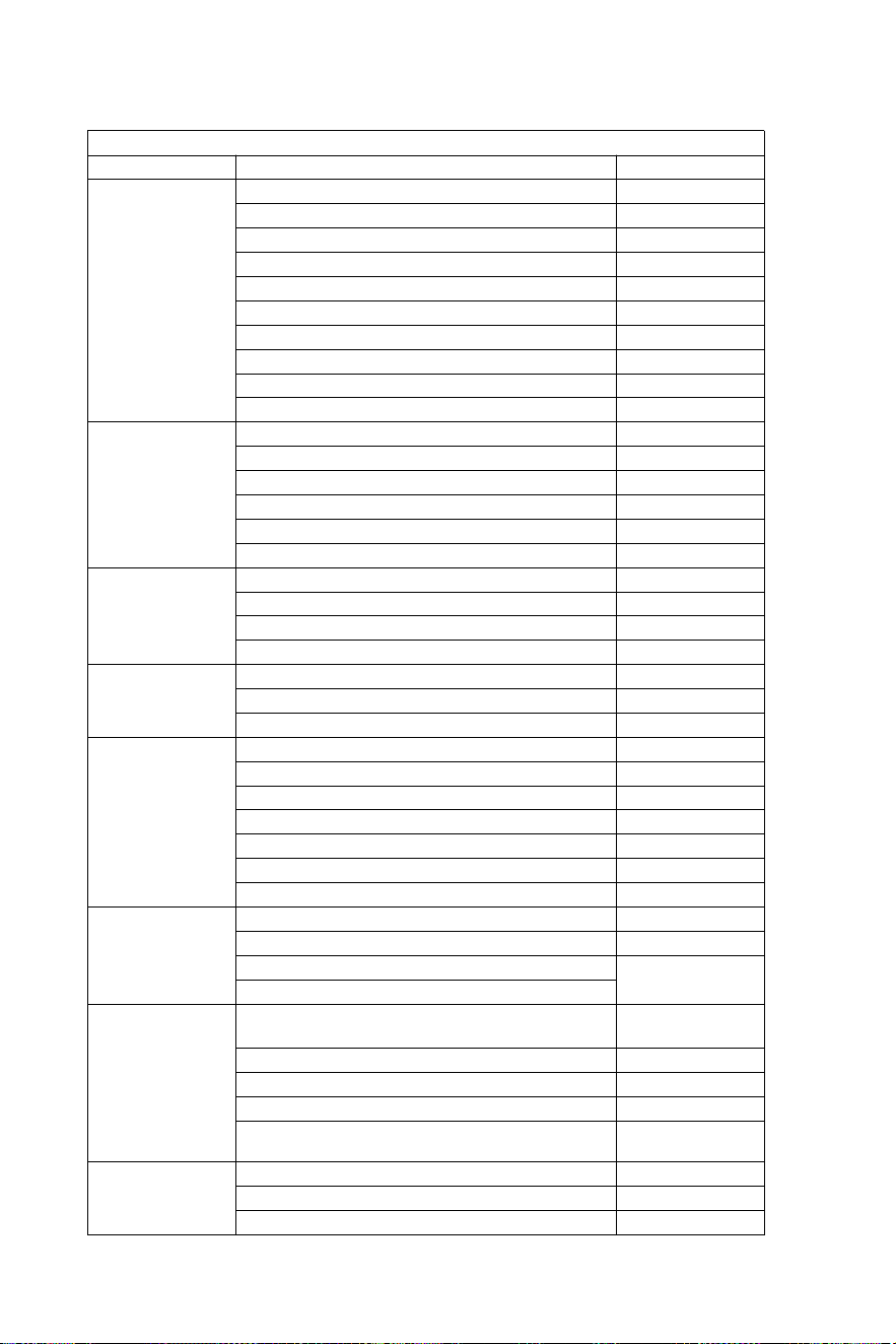
- 23 -
Übereinstimmen die Liste
HYDRAULISCHE LENKUNG BIS 150 PS
MOTOR
LEISTUNG
JAHR
Yamaha
60-702 Hub
1990–2008
75C-902 Hub
1998–2008
F70 4-Takt
2010-heute
115C-130B 2 Schlaganfall
1990–2008
150F
1996–2007
150 HPDI VMAX 2-Takt
2000–2008
F75-F80 EFI 4-Takt
1999–2007
F100-F115-F150 EFI 4-Takt
1999–2007
F80-F100 4-Takt
2000-heute
F115-F150
2004-heute
Honda
BF80-BF90 4-Takt
1995-heute
BF115D
1998–2009
BF115A
2009-heute
BF130A
1998–2005
BF135-BF1504 Hub
2005-heute
BF90-BF150V-TEC 4-Takt
2008-heute
Suzuki
DF70-80-904 Hub
1998-heute
DF100-115-1404 Hub"
1998–2008
DF100-115-1404 Hub neu Modell
2008-heute
Verteidigung 1504 Schlaganfall
2006-heute
Tohatsu
Nissan
70-902 Hub
2004-heute
115-120-1402 Schlaganfall
2004-heute
90-90-115TLD 4-Takt
2004–2011
Quecksilber
Seemann
75-90 2 Schlaganfall
1990–2008
115-125-150 EFI 2-Takt
1990–2007
90-115-125 Optimax 2 Schlaganfall
2004-heute
135-150 Optimax 2 Schlaganfall
1999-heute
80-90 EFI 4-Takt
2000-heute
100-115 EFI 4-Takt
2007-heute
150 Viertakt 4 Takt
2011-heute
Evinrude
E50-E55-E602 Schlaganfall
2004-heute
E75-E902 Schlaganfall
2004-heute
E115-E130-E1352 Hub V4
1995-heute
1995-heute
E1502 Hub V6
Wolkenstei
n
50-Madeira/Bullenhai-60 Grauhai /
St.tropez-70 Makohai 2-Takt
1996–2008
80 Portofino Tigerhai 2 Schlaganfall
1995–2008
150 Weißer Hai 2 Schlaganfall
2001–2007
50-60 Dorado EFI 4-Takt
2001–2007
100 EFI Marlin -115 EFINarwhal-150
EFI Killerwal 4-Takt
2000-heute
Johnson
BJ60-704 Hub
2001–2007
BJ90-115-140 4-Takt
2001–2007
J90-115V4 2-Takt
1995–2007
- 24 -
Warnung - Um die Verletzungsgefahr, Benutzer muss lesen
Anweisungen Lesen Sie das Handbuch sorgfältig durch.
Hersteller: Shanghaimuxinmuyeyouxiangongsi
Adresse: Shuangchenglu 803nong11hao1602A-1609shi,
baoshanqu, Shanghai 200000 CN.
Importiert nach AUS: SIHAO PTY LTD. 1 ROKEVA
STREETEASTWOODNSW 2122 Australien
Importiert in die USA: Sanven Technology Ltd. Suite 250,
9166 AnaheimPlace, Rancho Cucamonga, CA 91730
REP
UK
YH CONSULTING LIMITED. C/O YH Consulting
Limited Office 147, Centurion House, London
Road, Staines-upon-Thames, Surrey, TW18 4AX
REP
EC
E-CrossStu GmbH
Mainzer Landstr.69,
60329 Frankfurt am Main.

- 25 -
Sterzo idraulico Per barche
Modello : YSH -150 CV
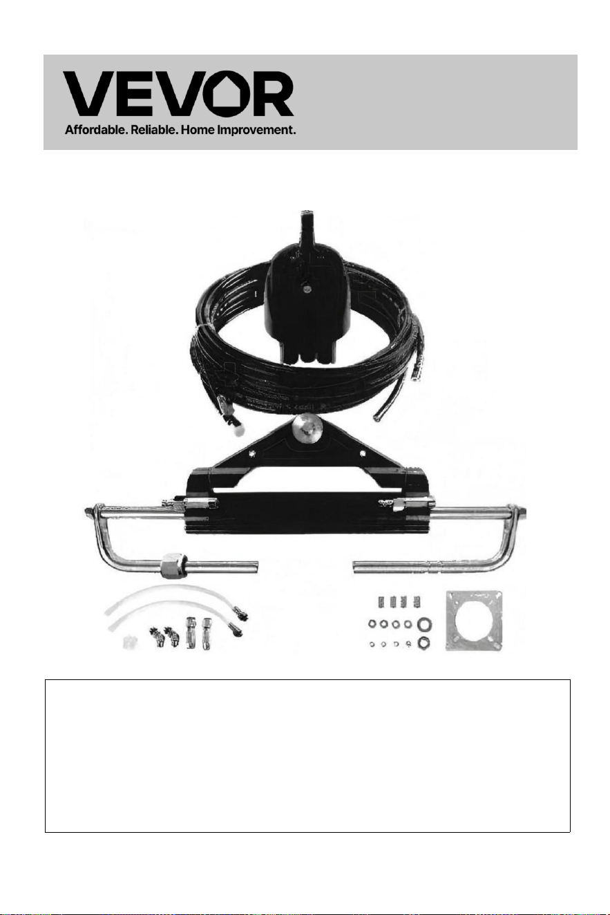
- 1 -
Sterzo idraulico
Per
Barche
Modello : YSH -150 CV
Questo è l'originale istruzione, per favore leggi tutto manuale
istruzioni
attentamente prima di operare. VEVOR si riserva il diritto di
interpretazione del nostro manuale utente. L'aspetto del prodotto
deve Essere soggetto al prodotto che ricevuto . Vi preghiamo di
perdonarci se non vi informeremo più se ci sono tecnologie o
software aggiornamenti sul nostro prodotto.
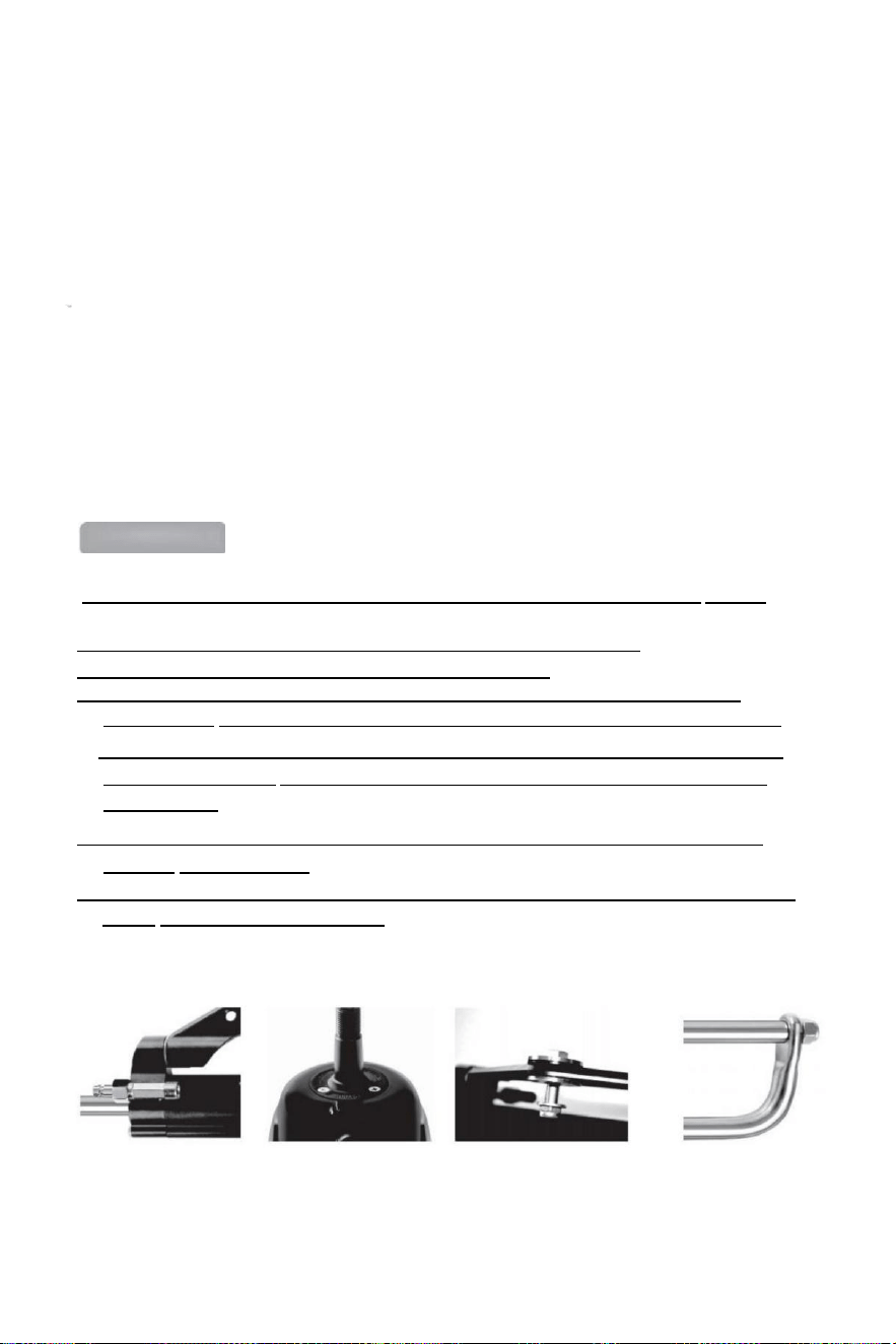
- 2 -
Grazie per aver acquistato il sistema di sterzo idraulico VEVOR.
Questo manuale illustrerà le varie funzioni di questo sistema in modo che tu Potere scopri
appieno il piacere esclusivo che questo prodotto può offrirti.
VEVOR idraulico sterzo il sistema è basato SU il concetto Di industriale moderno
progettare, il alto efficienza, alta trasmissione energia pistone pompa tecnologia È
applicato A IL progetto e fabbricazione di meccanismo di governo della nave, che
rende il tuo sterzo sistema più stabile, più intelligente e più affidabile.
Il principale componenti Di IL sterzo ingranaggio Sono alto forza alluminio lega E
acciaio inossidabile che può essere utilizzato in duro condizioni marine E estendere
il
longevità di m e c c a n i s m o di sterzo .
IL sterzo ingranaggio Volere alleviare Voi da IL pesante E inflessibile meccanico
lancia sterzo, che può salvare le tue braccia doloranti. Può aumentare il piacere di
guidare un motoscafo.
Main features:
● Lo sterzo pompa è con struttura interna compatta e alla moda E Bellissimo aspetto
.
●La valvola di bloccaggio integrata a due vie elimina la coppia di rimbalzo.
● Facile da sostituire l'albero t sigillo, facile da usare progetto ;
●Albero dello sterzo con speciale superficie trattamento non soltanto ha forza E
affidabilità, ma Anche ha IL caratteristiche di usura resistenza, corrosione resistenza.
● Ad alta resistenza alluminio lega conchiglia E superficie trattamento processo Potere
garantire la sua usura e resistenza alla corrosione e prevenire l'erosione dell'acqua
efficacemente.
● Tubazioni: nylon ad alta resistenza raccordi rapidi da 1/4 di tubo effettua l' installazione
compatto E è riutilizzabile .
●IL utilizzo Di costume alto -standard idraulico olio Potere migliorare IL lubrificazione Di
parti E protezione della guarnizione.

- 3 -
Norme generali di sicurezza e garanzia
manuale di installazione e manutenzione costituisce parte integrante parte di il
prodotto e deve essere pienamente compreso dall'utente prima dell'installazione .
L'installazione, la manutenzione e il trasferimento di idraulico direzione sistema
componenti di VEVOR serie Di i prodotti devono Essere Fatto di IL autorizzato E
qualificato professionale
tecnici.VEVOR serie Di prodotti strumenti IL garanzia per due anni se r v i z i o post-
vendita ,quando utilizzando il prodotto, se c'è qualche domanda o problema, contattare il
rivenditore nel tempo.VEVOR lo farà fornire la guida corretta. VEVOR non accetterà
responsabile per le conseguenze dello smantellamento o dello smontaggio non autorizzati.
Fatta salva la natura del prodotto, VEVOR ha la diritti A Fare cambiamenti A IL
descrizione informazioni su E illustrazioni contenuto In Questo manuale,VEVOR non si
assume alcuna responsabilità per le conseguenze negative causate dal coping questo
manuale in qualsiasi altri mezzi illegali che fa l'utente non può seguire IL
installazione standard nelle istruzioni.
Installazione Precauzioni:
● Utilizzo componenti fornito di Solo VEVOR, Il parti s fornito di IL altro i
produttori possono causa pericoli per la sicurezza E simulare IL sterzo
funzione;
●Su tutti i tubi connessione solo fili foche come come Loctite PST o equivalente
si dovrebbe usare il sigillante. Non usare (fasce) o nastri sigillanti simili, poiché ciò potrebbe
consentire detriti entrare il corpo Di la pompa E causa il blocco Di il tubo.
●Si prega di utilizzare 10# o 15# speciali olio idraulico qualificato e rispettoso dell'ambiente
amichevole. Utilizzare invece un altro olio (come l'olio dei freni) può causare danni
irreparabili A la tua attrezzatura, causando la perdita di sterzo funzione e nessuna garanzia.
●Il raggio minimo di curvatura del il tubo è 1"18 (30 cm). Non toccare il affilato
oggetti. Continua piegatura, sfregamento, graffio o la torsione può causare il tubo da essere
danneggiato e rottura dovuta A la normale pressione dello sterzo, causando così la perdita
di sterzo funzione.
●Non lasciare cadere il tubo liberamente quando si utilizza, si prega di utilizzare filo o altro
materiale in PVC per fissare, così come A evitare potenziali rischi per la sicurezza.
● Manutenzione regolare di componenti del sistema e ispezione delle tubazioni E raccordi
per indossare o danno può prolungare la durata di utilizzo Di tuo attrezzatura.

- 4 -
Lista imballaggio:
Codice
articolo
Modello
Accessori per l'imballaggio
Alto-
pressione
olio tubo
lunghezza
YYZXDB150HP0
5UTKJ001V0
YSH-
150 CV
Pompa idraulica*1
Piastra di montaggio*1
Manuale di
istruzioni*1 Oliatore
pentola*1
Tubi di riempimento dell'olio*2
Connettore a gomito da 135
gradi *2 Boccole di montaggio
*4
1/4 rondella*4
1/4-20UNC noci*4
Controdadi 5/8-18UNF *2
5/8 rondella*2
0
YYZXXTTJ90HPI
VK97001V0
YSH-
90 CV
Pompa idraulica *1
Cilindro dello sterzo idraulico
*1 Piastra di montaggio *1
Connettori a gomito da 135
gradi *2 Connettori rapidi *2
Boccole di montaggio *4
1/4 rondella*4
1/4-20UNC noci*4
Controdadi 5/8-18UNF *2
5/8 rondella*2
Trasparente tubo con connettore *2
Grasso di plastica capezzolo *1
Manuale di istruzioni *1
Oliatore *1
0
YYZXXTTJ90HP
DLO3P001V0
YSH-
90 CV
Pompa idraulica*1
Cilindro dello sterzo
idraulico*1 Tubi dell'olio ad
alta pressione*2
Piastra di montaggio*1
Gomiti da 135
gradi*2 Connettori
rapidi*2
Boccole di
montaggio*4
1/4
rondella*4
1/4-20UNC noci*4
Controdadi 5/8-18UNF *2
5/8 rondella*2
Trasparente tubi flessibili con
connettori*2 Grasso di plastica
capezzolo e*1
Istruzioni*1
Oliatore*1
20 piedi
YYZXXTTJ90HP
WYCCR001V0
YSH-
90 CV
24 piedi
YYZXXTTJ150HI
HNTU001V0
YSH-
150 CV
20 piedi
YYZXXTTJ150H
3TSCX001V0
YSH-
150 CV
24 piedi
YYZXXTTJ150H
3E857001V0
YSH-
150 CV
26 piedi
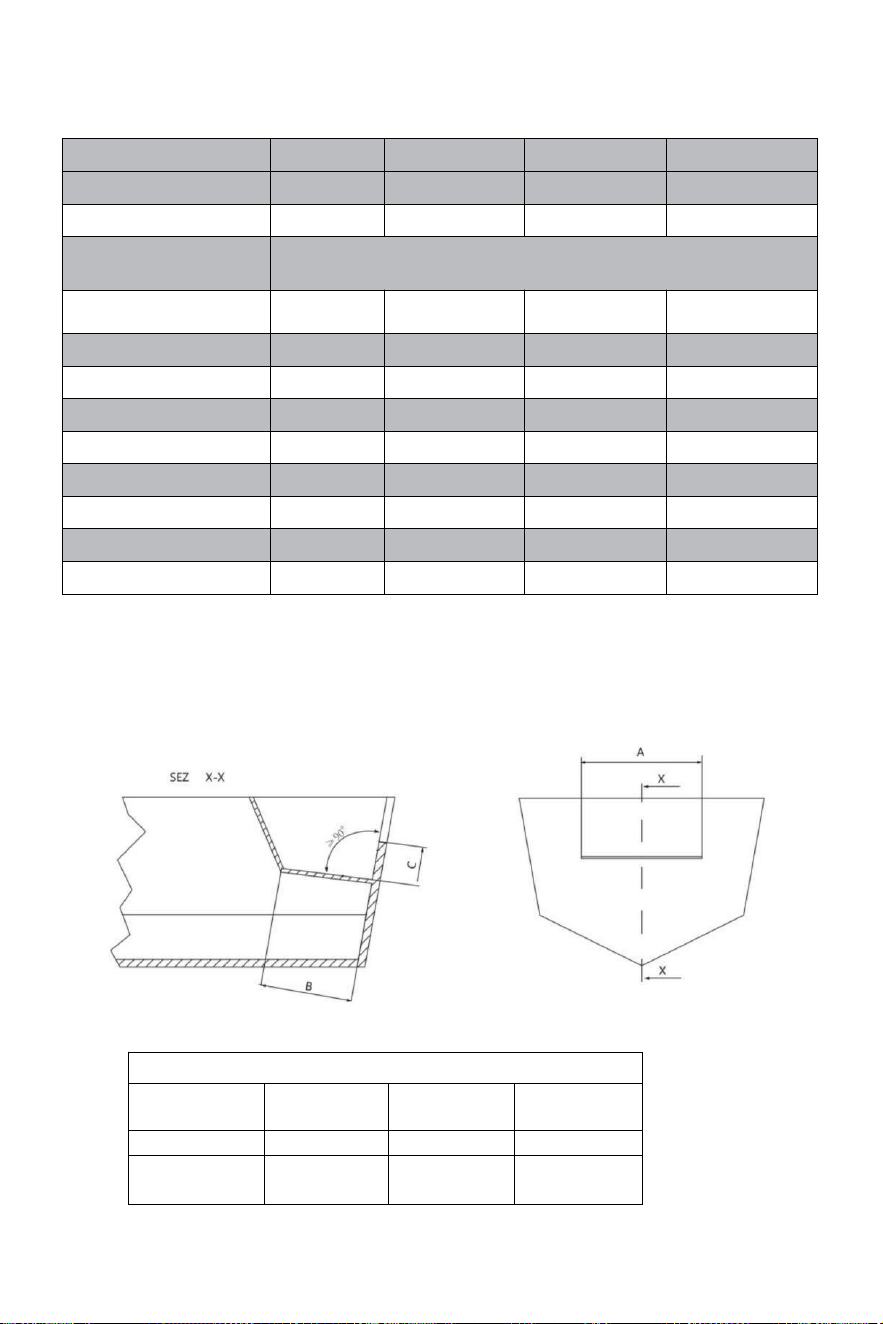
- 5 -
Tecnico informazioni:
TIPO
YSH-90HP
YSH-150HP
YSH-200HP
YSH-300HP-B
POMPE
NR90
NR150
NR200
NR300
CAPACITÀ cm³
16
18
27
27
Filettatura della
ruota
5/8"-18UNF
PRESSIONE MASSIMA
BARRE
69
69
69
69
GIRI DI RUOTA
5
5.5
6
7
CILINDRI
MR90
MR150
MR200
MR300-B
TUBO ID[mm]
25
30
32
35
ASTA ID[mm]
14
16
16
18
FORZA DI USCITA/KGF
232
400
470
470
CORSA[mm]
200
198
200
200
VOLUME [cc]
67
101
125
142
APPLICAZIONE
Fino
a 90 CV
Su A 150 CV
Su A 200 CV
Su A 300 CV
Dimensioni minime del pozzetto paraspruzzi:
Prima di tentare installazione,assicurarsi che il pozzetto di scarico del vostro
barca ha quanto segue mini mamma dimensioni.
DIMENSIONI MINIME DEL POZZETTO
Numero del
motores
UN
B
C
1
560 mm-21,25"
152 mm-5,98"
152 mm-5,98"
2
1110 mm-
21,55"
152 mm-5,99"
152 mm-5,99"
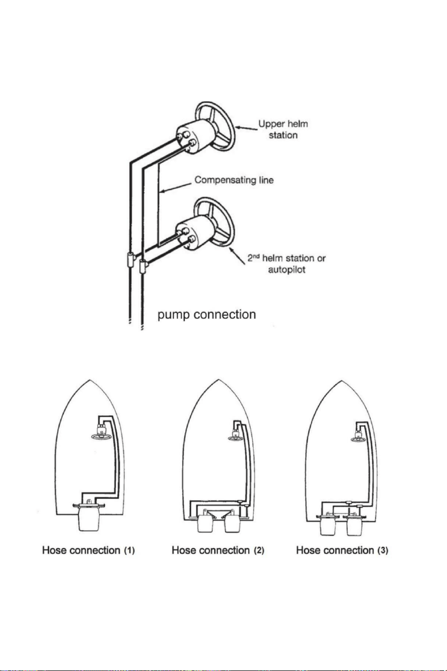
- 6 -
Installazione tubi/raccordi - collegamento pompa
Fare riferimento a illustrazioni sottostanti per il corretto collegamento dei tubi da timone dalla pompa
al cilindro.
Collegamento del tubo flessibile
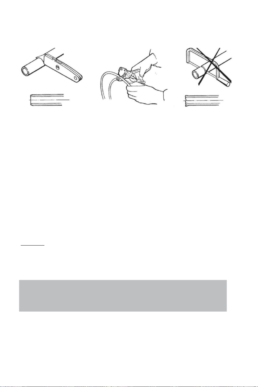
- 7 -
Collegamento del tubo flessibile
Consiglia IL utilizzo di VEVOR sterzo tubi flessibili soltanto.
Sempre Tentativo A itinerario IL tubi flessibili tramite IL il più corto sentiero In ordine A Evitare
Qualunque possibile perdita Di potere.In per fare IL aria sanguinamento del lui sistema più facile, è
suggerito montare i tubi
orizzontalmente con UN inclinazione di Di 3 cm per metro;il pompa lato ha A Essere più alto di
IL cilindro lato.
Sempre proteggere IL tubi flessibili Quello Avere A passaggio Attraverso UN diverso
compartimento t O utilizzo adatto connettori di paratia o manica s .
Tubo flessibile Avere A Essere installato In come UN modo Essi non rappresentare UN ostacolo
per altro componenti.
Fare non rimuovere protettivo FINE coperture Fino a IL tubi flessibili Avere stato instradato
E Sono pronto A Essere collegato A la pompa del timone , raccordo del tubo flessibile O
cilindro/i dello sterzo.
Fornire sufficiente tubo flessibile lunghezze A permettere per cilindro movimento per tutto IL
svolta arco E su/giù impostazioni di trim/inclinazione Di IL motore/i.
Per tutto IL tubo flessibile installazione, garantire IL protettivo tappi rimanere installato su IL
FINE Di IL tubi flessibili.
Attenzione:
Fare non installare tubi flessibili In UN zona Dove Essi Volere Essere esposto A alto calore .
Estremo Calore riduce la pressione di rottura del tubo e può causare il tubo fusione.Esercitare
grande pulizia.Fare Sicuro Quello tubi e tubi flessibili Sono perfettamente pulito E gratuito da
trucioli.
Note:
Flexible hoses have to be cut by means of a sharp knife;
never use a saw,as fragments of nylon in the hydraulic system cause serious problems.
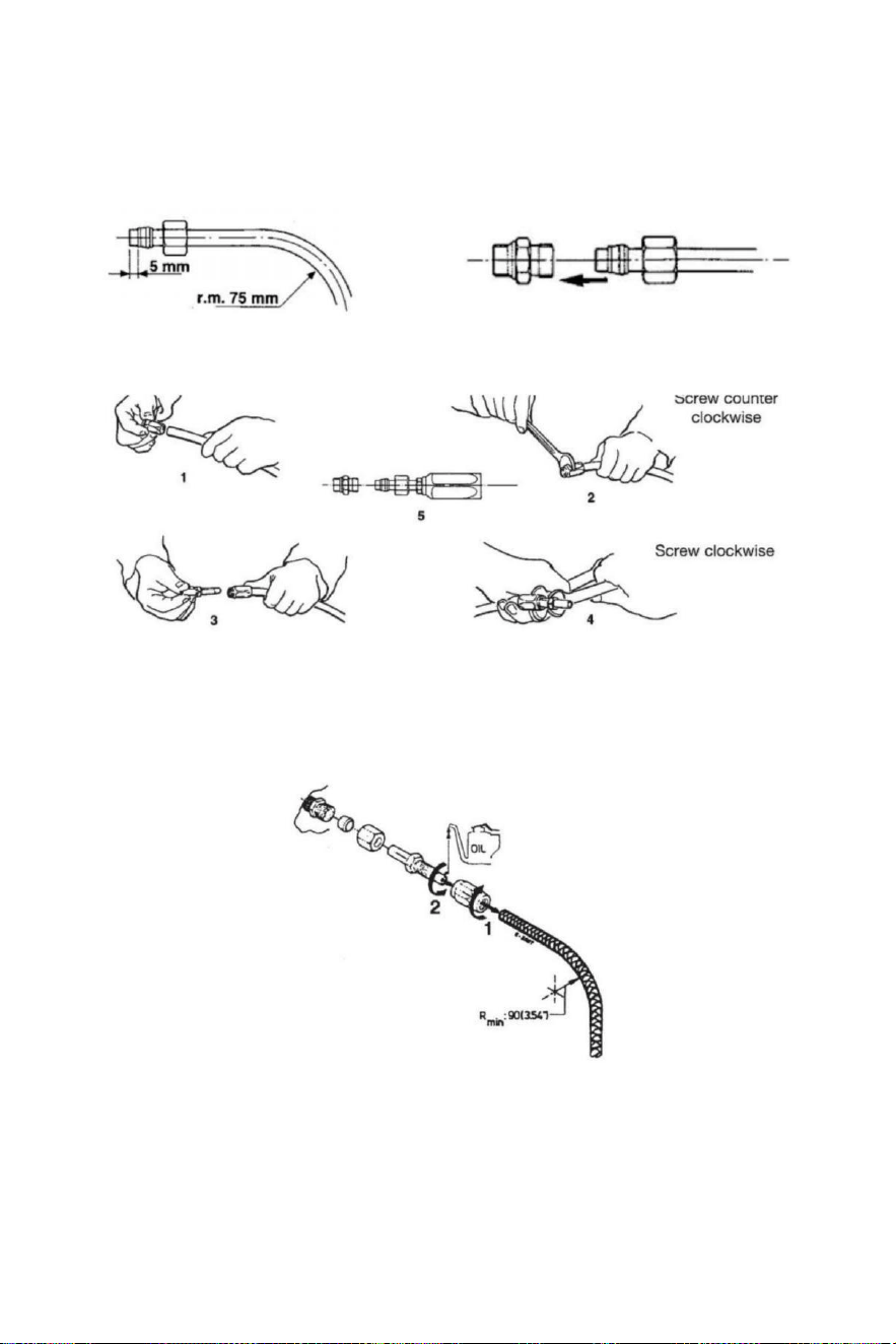
- 8 -
Installazione del tubo flessibile idraulico
Dopo aver tagliato il nylon tubo flessibile, montare il accoppiamento noce e IL supporto manica
SU il tubo (controllare Esso è propriamente in relazione al FINE del tubo).Dopo il montaggio del
matto , tu Avere A stretto di mezzo di un chiave inglese.
Altrimenti , tu Potere montare tubo flessibile in nylon con raccordi recuperabili.Fare come il
illustrazioni sotto spettacolo.
Dopo IL installazione pulito IL dentro Di IL tubi flessibili di soffiando Attraverso usando
compresso aria , in ordine A Evitare Qualunque ostacoli E A rimuovere polvere E detriti da
stoccaggio.Prima IL sanguinamento dell'aria Esso È Anche suggerito A Fare UN risciacquo Di
IL sistema . Fare non utilizzo acqua .
1 Dopo il taglio, avvitare il giunto per tubi manica su il tubo ( mancino filo).
2 Oliare il raccordo del tubo E vite nella manica.Rendi Sicuro Quello il rivestimento interno Di
la
dose del tubo
non seguire durante il serraggio del vite! Assicurati anche Quello l'interno
rivestimento Di IL tubi È non spremuto Mentre serraggio IL vite .
3 Controlla Là È NO interno interferenza mettendo UN piccolo cacciavite in IL tubo
accoppiamento prima procedere con l'installazione del tubo flessibile al timone o cilindro
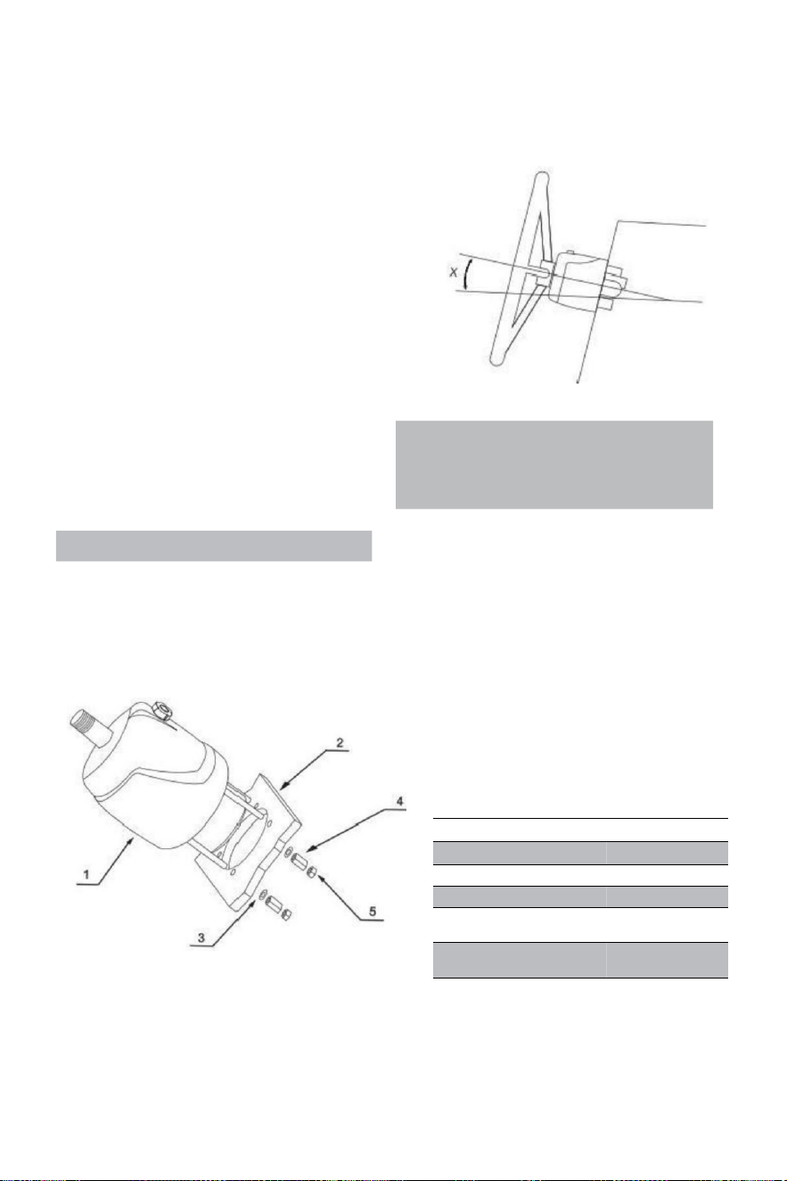
- 9 -
Sistema di direzione idraulico YSH-150HP
Strumenti di installazione (Per completare il installazione di
questo sistema , Voi sono necessari i seguenti strumenti):
. Buco sega con 3 . 03 " (77 MILIONI )
diametro · 0 . 354 " (9 MILLIMETRI )
trapano morso
· 1 . 181 " (30 MILLIMETRI ) montaggio chiave
· 0 .433 " ( 11 MM ) installazione chiave
· 0 . 748 " ( 19 MM ) installazione chiave
· 0 . 669 " ( 17 MM ) installazione chiave
· 0 .472 " ( 12 MM ) installazione chiave
· 0 . 945 " (24 MILLIMETRI ) PRESA chiave
Important:
perform the bleeding procedure manually
and with the helm pump inclined no
more of 10(X).
Steering pump YSH-150HP Installation:
·Determina l'angolo e posizionarti stanno installando garantire Quello IL volante fa non
interferire con altre apparecchiature. Verificare che ci sia ancora sufficiente spazio dietro IL
ponte cruscotto(2) per raccordi e collegamenti tubi.
RIF.
QUANTITÀ
DESCRIZIONE
1
1
pompa
2
1
Asse
3
4
Spessore
4
4
Dado di
prolunga
5
4
Serratura
noce
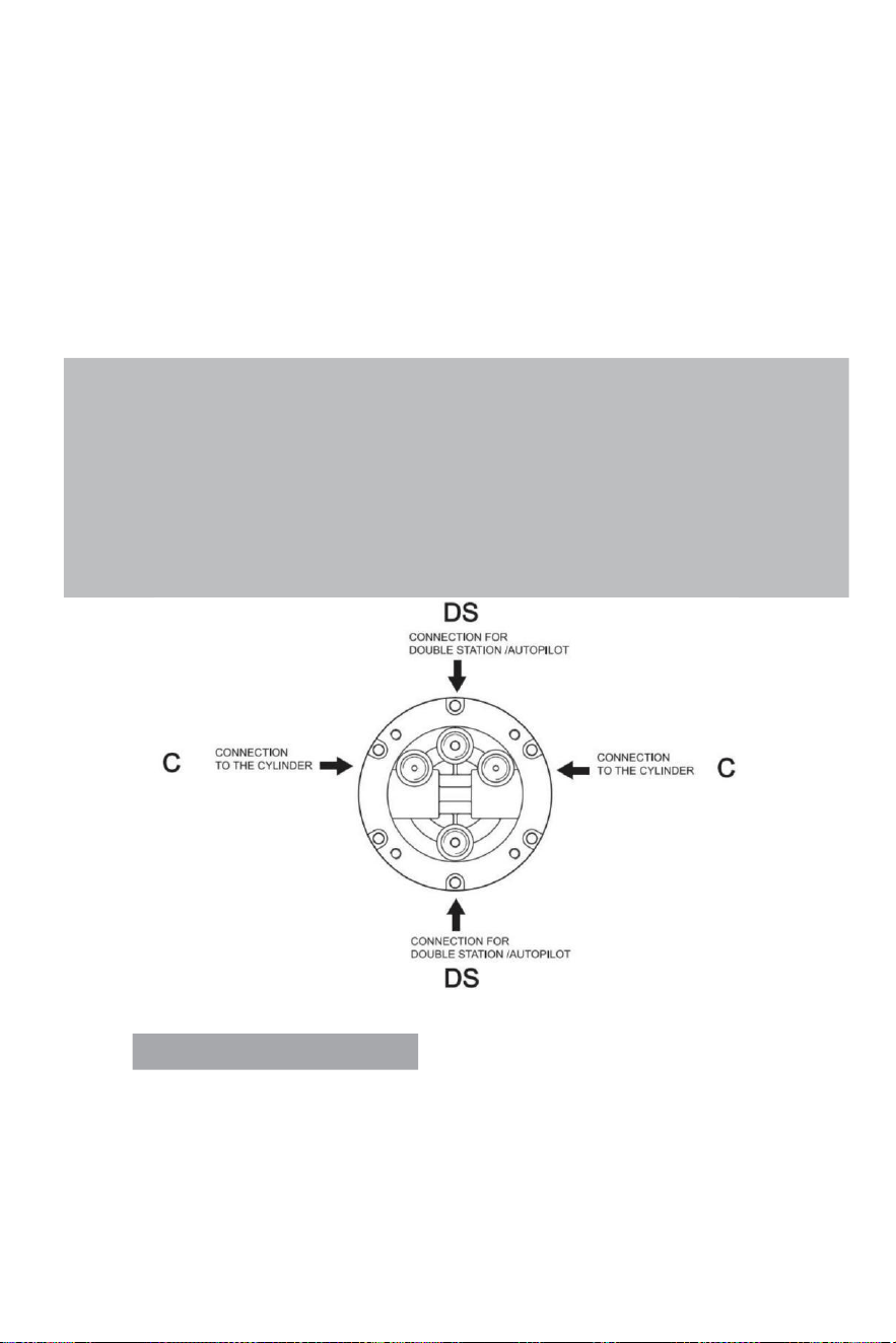
- 10 -
·Allegare a1:1 accesso buco montaggio modello (incluso con Questo manuale) a IL strumento
pannello e posizionare il montaggio foro di serie con un fresa per fori.
· Trapano un diametro di 3,03" (77 mm ) buco E trapano quattro 0,354 (9 mm ) di diametro
buchi COME mostrato SU il modello di montaggio.
·Itinerario IL organizzato tubi Attraverso IL mezzo Diametro 3,03"(77 mm) buco E collegare
Esso A lo sterzo pompa (1)
·Installare IL sterzo pompa SU IL strumento pannello con 4 rondelle (3) e 4 sollievo dalla pioggia
noci(4),4 controdadi (5) , serraggio coppia ≤15N.
·Lubrificare IL cono sezione del albero.Installare IL semicircolare chiave.Luogo IL sterzo ruota In
IL albero di direzione e il volante chiave avanti così IL semicircolare chiave.Luogo IL spessore E
stringere il sterzo serratura dado . Il serraggio coppia È ≤20 Newton .
Note:
·The steering pump should be mounted at a tilt angle of X≤20°.If it is exceeded,it
may cause air to enter the duct and affect the steering function.
·Only use self-locking fasteners provided by VEVOR or standard fasteners.Using non-self-
locking fasteners instead may cause the equipment to loosen or separate.
·Do not open the pump cover or filler cap when installing the steering pump to prevent dirt
and chips from entering the pump and causing the steering function.
·Teflon-like ribbon seals can not be used on pipe nipples,which may cause tape chips to enter
the pump body and thus affect the steering function.(The VEVOR series is a pipe thread
sealing technology that does not require the use of other sealing tape seals.)
VALVE PORTS CONNECTION:
Porta contrassegnata con “C”: collegamenti al/ai cilindro/i
Porta contrassegnati con “DS”: collegamenti alla stazione aggiuntiva o pilota automatico
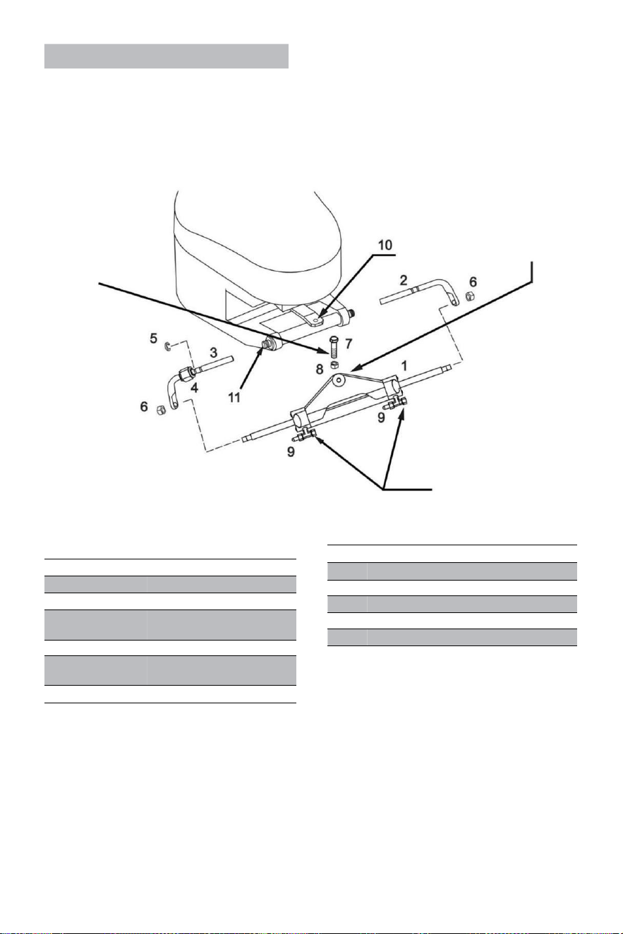
- 11 -
Cylinder YSH-150HP Installation:
AVVERTIMENTO:
Esso È importante A controllo
periodicamente , a meno
ogni 3 mesi (o ogni mese
per usi professionali), il
Giusto coppia di questo
bullone E del serratura noce.
Il braccio del cilindro dovrebbe
essere attaccato di IL
motore timone braccio
sulla maggior parte marche
Di fuoribordo nell'evento
Quello IL timone interferisce
con altre parti del fuoribordo,
Poi può Essere montato
sotto il timone Invece.
AVVERTIMENTO:
Rimuovere i tappi rossi in
ordine A installare IL tubo
flessibile raccordi .
RIF .
QUANTITÀ
DESCRIZIONE
1
1
Cilindro
2
1
Supporto giusto parentesi
3
1
Supporto sinistro
parentesi
4
1
Collegamento noce
5
1
Inossidabile fibbia in acciaio
(C)
6
2
Biella bloccaggio noce
·Prima provando A installa, per favore controlla se il tuo il motore è adatto per questo tipo
del cilindro , e garantire Quello tuo poppa asse spazio È Di sufficiente misurare per
installazione .
· Prima installazione , per favore lubrificare IL mobile connessione parti Di IL motore E
il cilindro
E IL pistone asta con personale marittimo qualificato lubrificante , e raddrizzare tuo motore A
il mezzo posizione;
·
RIF.
QUANTITY
DESCRIPTION
7
1
3/8 connecting bolt
8
1
3/8 Lock nut
9
2
Deflation device
10
1
Engine connecting block
11
1
Engine mounting hole
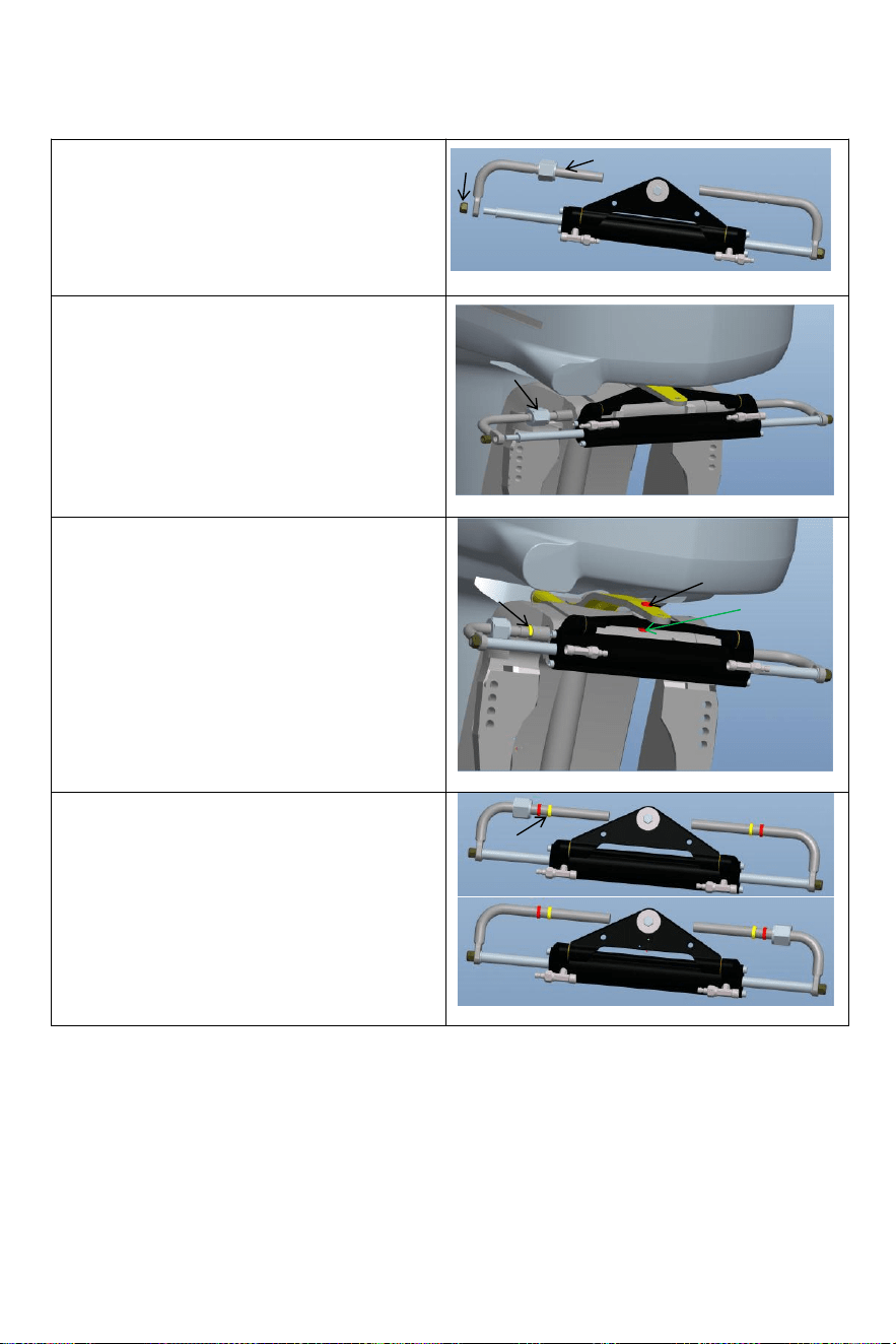
- 12 -
Allentare l'autobloccante dado(6)su un'estremità
del cilindro pistone asta, e rimuovere IL
installazione asta (3).Dopo rimozione IL parti,
installare
installazione asta (3)in IL motore installazione
buco(come mostrato nella figura Sopra);
Rimuovere il bullone (7) dal centro buco del
cilindrico triangolo parentesi staffa,regolare
l'angolo del motore e fissare il cilindro triangolo
parentesi A IL motore con bullone(7)e
noce(8)
corrispondente A il buco su la piastra di
collegamento del motore. Prestare attenzione a
l'oscillazione sinistra e destra Di IL macchina A
garantire Quello IL cilindro Volere non
interferire con IL movimento Di IL motore Dopo
installazione.
Regolare IL motore Angolo E cilindro pistone
asta estensione lunghezza.Secondo A IL
spacco fra il motore e il cilindro correttamente
installare il inossidabile acciaio Morsetto a C
(5) in IL appropriato scanalatura del montaggio
asta.(Vedi figura Sopra)
6
3
4
5
7
8
5
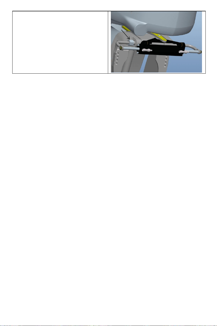
- 13 -
Dopo l'installazione, il dado di bloccaggio (4) deve
essere stretto A eliminare IL operativo
sdoganamento del cilindro.Questo migliorerà la tua
esperienza.
4

- 14 -
· Dopo IL installazione È completare , spingere tuo motore A IL Sinistra E Giusto A Fare UN
prova correre del cilindro. Verificare se ci sono parti di interferenza quando il cilindro è in funzione
avanti e indietro . Se Là È interferenza , tu Bisogno A riaggiustare IL installazione . Se Là È
NO
interferenza , spinta IL motore A IL FINE Di IL sinistra / destra limite . Il Prossimo fare un
passo È A fare rifornimento e scarico;
· Connetti IL organizzato olio tubi A IL olio tubo giunti (2) in sequenza , blocco IL sanguinare
giunti(3)del cilindro preparare per il prossimo rifornimento di carburante E estenuante g passi
per l'installazione IL sistema.
Warning:
When installing,to avoid bumping the piston rod,it is forbidden to hit the piston rod with wrench or
anything hard.If the piston rod is bruised,it will cause hydraulic oil leakage of the oil cylinder,
which will compromise your product experience.
Direzione idraulica VEVOR diIL sistema di gas di scarico:
Questo la procedura di lavoro richiede due persone da gestire,a persona Maggio non Essere in
grado di rimuovere completamente Tutto IL aria dentro IL idraulico sistema Quale risultati In
Quello IL idraulico output di sistema pressione È non abbastanza, l'impatto della debolezza
che riconosciamo, risposta lenta, quindi
che influiscono sulla tua esperienza con il prodotto.
Si prega di utilizzare speciale
o l i o
idraulico ecologico fornito da VEVOR O altro qualificato speciale
idraulico olio per il rifornimento. Non utilizzare olio freni.Utilizzando altri corrosivi inaccettabili
l'olio può causa danni irreparabili al tuo sistema E risultato nel prodotto essendo incapace A
Essere
garantito.

- 15 -
Precautions:
·If you fill the pump with hydraulic fluid before connecting the filler tube to the pump,the
filling procedure can be made more quickly and easily.
·In case of emergency,any non-toxic,non-corrosive,non-flammable oil can be temporarily
supplied to the system,but the entire system must be thoroughly cleaned afterwards;
·Please keep refueling tube visible during the entire refueling process.Do not allow oil to
enter the pump. Otherwise,air may be introduced to increase refueling time.
·During the process of refueling and exhausting,the hydraulic oil collected from the air
bleeder manifold of the cylinder can be used directly after a few moments.
·Please protect the environment and properly dispose of used oil.The special hydraulic
oil provided by VEVOR system can be reused after being filtered by the filter with the hole
diameter less than or equal to 38um.
Le questioni richiedono attenzione
Nota 1 Utilizzare lo specificato Viscosità 20 #-32# Di idraulico olio, Fare non utilizzo diverso tipi Di
idraulico olio con diversa viscosità, d o non miscela idraulica olio con Qualunque sconosciuto liquido.
Nota 2 Fai non utilizzo impuro olio idraulico, impuro l'olio idraulico sarà causa idraulico pompa
fallimento E rumore.
Nota 3 Aggiungi olio idraulico al idraulico pompa a IL riempimento specificato porta A Evitare
miscelazione acqua O impurità. Il olio idraulico dovere Essere mantenuto in stato di olio completo
nel idraulico pompa.
Nota 4 Quando si aggiunge olio idraulico , dovrebbe essere filtrato con UN filtro schermo. NO Bene
inquinanti Di Di più più di 5μm-10μm possono entrare nell'olio pompa, che Volere causa parti blocco,
rumore, direzione commutazione valvola mordere, e fare il olio pompa fallire.
Nota 5 Dovrebbe esserci Essere NO bolle nel olio idraulico, che aumento IL rumore del idraulico
pompa e causa (causa (sconosciuto) fallimento. Bolle d'aria dovere Essere dimesso. Per favore fare
riferimento a pagine 11 E 12 del manuale per il funzionamento specifico dello scarico metodi
Nota 6 Nella processo di utilizzo, Esso È necessario A controllo regolarmente se Là È olio perdita
ge In IL pompa corpo, olio tubo e olio cilindro E affrontare Esso In tempo .
Nota 7 Volante giocare può Essere risolto applicando pressione A IL sterzo ruota. IL
procedura è il seguente: girare il volante in senso orario per completare serratura. Continuare svolta
IL sterzo ruota finché non ti senti importante resistenza. Poi svitare il bocchettone del carburante
berretto E continuare riempimento IL carburante pompa con olio. Serrare il tappo del serbatoio del
carburante, E IL sterzo ruota giocare Volere Essere eliminato.
Nota 8 Durante il riempimento dell'olio pompa con olio, Per favore utilizzare il olio riempitivo
ugello fornito di noi, Quale È dotato di filtro dell'olio da 60 mesh A filtro fuori impurità In IL olio.
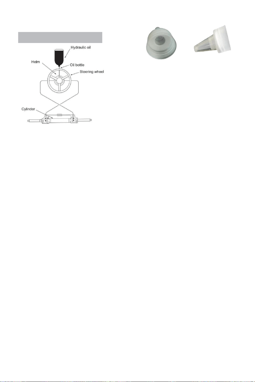
- 16 -
Refueling and Venting Steps:
·Avvitare la filettatura del tubo di raccordo dotato di sistema
nella porta della pompa di alimentazione e serrare per garantire la tenuta stagna.
·Adatto il monte affilato incluso con questo sistema A
IL olio tappo di bottiglia.Inserisci IL bocca affilata nella
pompa
con un po' di forza, versare l'olio nel tubo di rifornimento del
carburante
finché non riesci a vedere l'aria (il bottiglia Potere essere
spremuto delicatamente A velocità su rifornimento.)
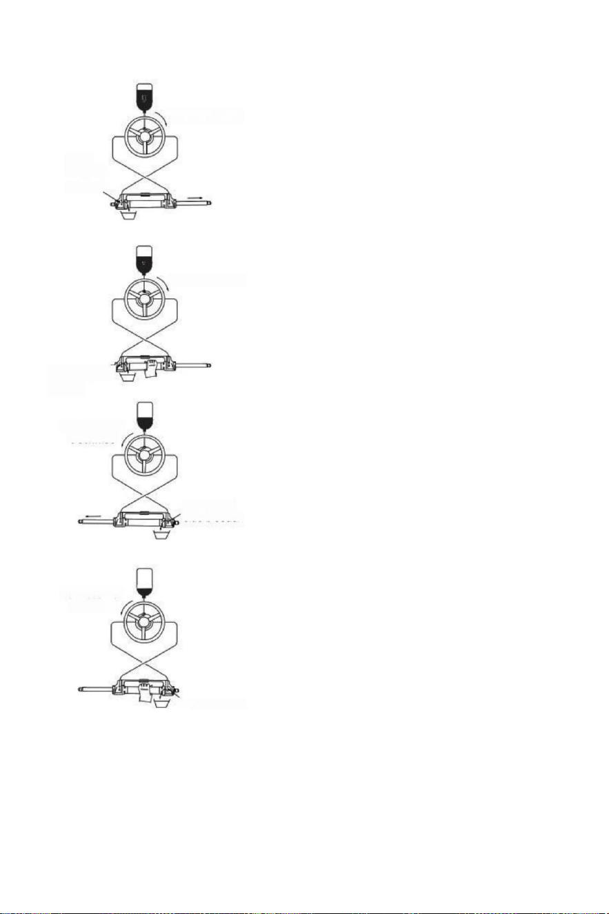
- 17 -
(parameter table)to determine whether the hydraulic
Turn clockwise
Open
left side
bleeder
Turn clockwise
Close left side
bleeder
Turn counter
clockwise
Open right
side bleeder
Turn counter
clockwise
·Giro lo sterzo ruota lentamente in senso
orario fino a un lato del pistone asta è
completamente
esteso.Adatta il tubo di scarico A la
ritrattazione lato del pistone asta A
raccogliere l'olio da sfogo.
·Presa IL cilindro A impedire IL cilindro da svolta,
svitare IL sgonfiare il capezzolo n ested SU IL
lato Di lo spurgo (non svitare) Esso
completamente, è abbastanza se
Voi Potere Vedere IL olio)girare IL sterzo
ruota in senso orario fino a Voi Vedere IL
dentro del lui
scarico tubo Espulso
olio È stabile E approfondito , no bolle , girare
il volante al Stesso tempo stringere IL
dado di sgonfiaggio raccordi di scarico ravvicinati ;
·Continuare A giro IL sterzo ruota
in senso antiorario fino a quando origine al
retrazione lato Di l'asta del pistone
completamente estesa, Fit IL ex h aust tubo
A IL ritrattare lato del pistone asta A
raccogliere IL olio da sfiato
·Tenere il cilindro per prevenire IL cilindro
dal girare, svitare il dado del giunto di sgonfiaggio
di uno lato.(Non svitare è completamente , è
Abbastanza COME lungo COME Voi Potere
Vedere IL
olio).Girare IL sterzo ruota in senso orario finché
non Vedere IL olio da IL il tubo di sgonfiaggio è
stabile, no bolle, stringere il sanguinante
bloccare, chiudere
deflazione dispositivi.
·Ruotare il volante in senso orario/antiorario
parecchi volte A controllo il numero Di giri di timone
completi
fluido nel tubo ha stato completamente escluso.Se
c'è Ancora aria, il numero Di timone completo
aumenterà .)
Se Là È Ancora UN quantità di aria che È non escluso,
quindi ripetere
procedura (3)~(6). Se Là È UN piccolo quantità Di
aria , fare
pieno timone In uno diretto, inverso piccolo s emi
cerchio, fare pieno
di nuovo il timone, fallo Questo per 5-6 volte per la
direzione sinistra
E Giusto direzione.
·Dopo in giro timone test passa, rimuovi IL carburante
tubo E tubo di spurgo, vite il carburante tappo, set IL
sgonfiato connettore manica, il inutilizzato idraulico olio
Close right side
bleeder

- 18 -
È Chiuso per successivo manutenzione e
riparazione.(Controllare l'impianto idraulico
pu m p olio superficie una volta quarto,
insufficiente olio Volere causa
qualcosa di anormale.)

- 19 -
Errori e soluzioni:
IL seguente Sono IL maggior parte comune fallimenti E loro cause E soluzioni .
Quando IL timone ruota con pieno timone (cilindro pieno) ictus ), lì Forse lieve resistenza
E interno parti fanno clic sul suono che è da valvola interna piscina palla E cuscinetto
acciaio palla quando loro Sono corsa.
È normale fenomeni. Per favore Fare non pensare Esso È causato di difetti.
COLPA CAUSA SOLUZIONE
L'idraulico timone È
completamente incollato
durante installazione.
Tubo blocco fra
l'idraulico pompa E
cilindro idraulico.
Controlla se IL tubo flessibile tubo È
intasato O piegato, se è così È piegato,
devi sostituire il tubo danneggiato, o
potrebbe risultato nel perdita di sterzo
E serio lesioni personali o proprietà
danno.
Esso è difficile A fare
rifornimento IL sistema,anche
Quando IL
sistema dice IL carburante È
pieno, bolle continuare A
pop fuori da IL olio pompa.
·Là È aria In IL sistema
·Sanguinare montaggio perdite
· Idraulico pipping ha
avvolgimento O piegatura
lesioni
.Installare ilsistema correttamente
secondo al manualedi installazione.Il
ingresso tubo dovere Essere Sempre
verso l'alto.
·Stringere IL deflazione raccordi.
·Rilassarsi E dritto IL tubo
flessibile O sostituire IL
danneggiato tubo flessibile.
Quando usando IL sistema
A sterza, hai bisogno A
ruotare il timone completo
velocemente per molti volte.
·Idraulico pipping ha
piegato ferite
·Là È gas O Bene bolle In IL
idraulico olio.
· Idraulica non corretta olio siamo
stati noied
·Rilassarsi E raddrizzare IL
tubo o sostituire IL danneggiato tubo
flessibile.
·Fare rifornimento O scarico
correttamente
secondo il manuale diinstallazione .
·Utilizzo IL corretto idraulico olio
Quando IL sistema È
pieno timone, il sterzo
ruota Appena non lo fa lavoro.
Ci sono sporco impurità In
IL idraulico pompa
valvola
·Non utilizzo IL sigillatura a "banda"
nastro A IL interfaccia.
·Prendere a parte IL idraulico pompa
A pulito IL sporco.
IL il sistema può sterzare
IL nave facilmente quando IL
nave È stazionario,Tuttavia,
Esso è molto difficile A
sterzare Mentre navigazione.
·Volante piccolo era
selezionato.
·Motore connessione È
non impostato
correttamente,
.Airbag È generato In
IL sistema E aria non è
escluso completamente.
·Sistema configurazioni
superare energia limiti.
·Cambia in UN più grande sterzo
ruota Di Quale IL massimo diametro
È senza superiore 56 cm.
·Regolare IL motore collegare
ione impostazioni
correttamente.
·Controlla il olio superficie di idraulica
pompa, reimpostare il rifornimento e
ventilazione correttamente.
Volante giri A Sinistra
porta lato,
Nave gira a destra
Olio sbagliato tubo connessione
Scambiai due olio tubi Di IL cilindro con
l'un l'altro E installare loro .
Il cilindro può non Essere
installato A IL motore.
Ogni cilindro richiede
corrispondente motore modello.
Si prega di fare riferimento a IL
manuale O IL assistenza clienti Di
IL rivenditore A modifica IL modello.
Quando IL timone pompa raggiunge IL fermare punto(cilindro pieno ictus),a piccolo quantità Di
idraulico deriva È normale E IL timone pompa È non Bloccato al 100%.

- 20 -
Manutenzione
Avvertimento:
Seguente IL routine manutenzione orari COME delineato sotto,in IL lasso di tempo notato sarà
garantire anni di servizio dal tuo sistema di sterzo VEVOR e Mantenere Voi E tuo passeggeri
sicuro da IL
pericoli presenti SU E fuori dall'acqua.
Fallimento A conformarsi con manutenzione controlli Maggio risultato N perdita Di
sterzo,causando proprietà danni e/o personale infortunio.
Le ispezioni sono necessarie ogni anno e dovere Essere portato fuori di specializzato marino
meccanica. Controllo IL lancia E IL o anelli del cilindro, il o anelli del timone pompa, la
raccordi del
cilindro E pompa del timone In ordine di impedire perdite.
Controllo tenuta Di Tutto elementi di fissaggio/ raccordi per tutto IL sterzo sistema.
Pulisci il sistema utilizzando acqua dolce E non abrasivo liquido.
Pulizia fluidi contenente ammoniaca, acidi O Qualunque altro corrosivo ve ingredienti dovere
non Essere usato per pulizia di qualsiasi parti del idraulico c sterzo sistema.
FARE non utilizzo freno oli O automatico trasmissione fluido(ATE).Uso soltanto compatibile con
idraulico oli.
Precedente A ogni utilizzo:
· Controllo Fluido livello In più alto timone pompa
·Verifica immediata risposta dello sterzo Quando svolta sterzo
ruota/e (Assicurarsi motore giri Quando sterzo la ruota è girato).
· Visivamente ispezionare Tutto sterzo tubi flessibili E adattare t ings per usura , piegatura e / o
perdite .
·Controllare se ci sono legature, allentamenti o usura O sterzo che perde componenti.
Avvertimento:
FARE NON operare barca se presente componente È non In funzionamento corretto
condizione .
In Questo caso, per favore Prendere foto immediatamente E contatto tuo rivenditore.
Dopo Primo 20 ore , poi ogni 100 ore O 6 mesi da allora in poi ( che mai viene Primo ):
· Tutto punti notato Sopra
·Controllo tenuta Di TUTTO elementi di fissaggio /raccordi per tutto IL sterzo
sistema.Stringere A corretto sono richieste specifiche di coppia .
·Controllo per gioco meccanico O brodaglia per tutto sterzo sistema ,corretto come richiesto.
·Controllo per segni Di corrosione.Se è presente corrosione contatto tuo rivenditore.
Dopo ogni 200 ore o 12 mesi ( che mai viene Primo ):
· Tutto punti notato Sopra .
·Rimuovere supporto asta da motore sterzo/inclinazione tubo.Pulito motore sterzo /inclinazione
tubo E ingrassare nuovamente utilizzando un Bene qualità m arina grasso.
·Ingrassare l'asta di supporto liberalmente.
·Grasso Tutto contatto punti mostrato In IL cilindro E cravatta sbarra installazioni.
FARE NON rimuovere il timone bullone a ingrassare nuovamente.
·Rimuovere volante E ingrassare nuovamente ruota lancia usando UN Bene qualità m arina
grasso.
·Ispezionare l'olio idraulico per verificarne la pulizia, sciacquare se necessario.
Qualsiasi lavoro essendo eseguito con il sistema di sterzo DOVERE Essere completato da un
qualificato meccanico con il lavoro conoscenza del sistema.
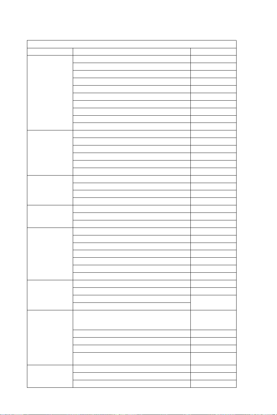
- 21 -
Incontro la lista
SISTEMA DI STERZO IDRAULICO FINO A 150 CV
MOTORE
ENERGIA
ANNO
Yamaha
60-702 Corsa
1990-2008
Corsa 75C-902
1998-2008
F70 4 tempi
2010-oggi
115C-130B 2 Colpo
1990-2008
150 °F
1996-2007
150 HPDI VMAX 2 tempi
2000-2008
F75-F80 EFI 4 tempi
1999-2007
F100-F115-F150 EFI 4 tempi
1999-2007
F80-F100 4 tempi
2000-oggi
F115-F150
2004-oggi
Honda
BF80-BF90 4 tempi
1995-oggi
Modello BF115D
1998-2009
Modello BF115A
2009-oggi
Modello BF130A
1998-2005
Corsa BF135-BF1504
2005-oggi
BF90-BF150V-TEC 4 tempi
2008-oggi
Suzuki
Corsa DF70-80-904
1998-oggi
Corsa DF100-115-1404"
1998-2008
DF100-115-1404 Corsa nuova modello
2008-oggi
DF 1504 Corsa
2006-oggi
Tohatsu
Nissan
70-902 Corsa
2004-oggi
115-120-1402 Ictus
2004-oggi
90-90-115TLD 4 tempi
2004-2011
Mercurio
Marinaio
75-90 2 Colpo
1990-2008
115-125-150 EFI 2 tempi
1990-2007
90-115-125 Optimax 2 Colpo
2004-oggi
135-150 Optimax 2 Colpo
1999-oggi
80-90 EFI 4 tempi
2000-oggi
100-115 EFI 4 tempi
2007-oggi
150 Quattro tempi 4 tempi
2011-oggi
Evinrude
Corsa E50-E55-E602
2004-oggi
Corsa E75-E902
2004-oggi
E115-E130-E1352 Corsa V4
1995-oggi
1995-oggi
E1502 Corsa V6
Selva
50-Madeira/Squalo toro-60 Squalo
grigio/ St. Tropez-70 Mako shark 2
tempi
1996-2008
80 Portofino Tigershark 2 Colpo
1995-2008
150 Squalo bianco 2 Colpo
2001-2007
50-60 Dorado EFI 4 tempi
2001-2007
100 EFI Marlin -115 EFINarwhal-150
EFI Orca assassina 4 tempi
2000-oggi
Johnson
Corsa BJ60-704
2001-2007
BJ90-115-140 4 tempi
2001-2007
J90-115V4 2 tempi
1995-2007
- 22 -
Attenzione - Per ridurre il rischio di lesioni, utente dovere
Leggere istruzioni manuale con attenzione.
Produttore: Shanghaimuxinmuyeyouxiangongsi
Indirizzo: Shuangchenglu 803nong11hao1602A-1609shi,
baoshanqu, shanghai 200000 CN.
Importato in AUS: SIHAO PTY LTD. 1 ROKEVA
STREETEASTWOODNSW 2122 Australia
Importato negli USA: Sanven Technology Ltd. Suite 250,
9166 AnaheimPlace, Rancho Cucamonga, CA 91730
REP
UK
YH CONSULTING LIMITED. C/O YH Consulting
Limited Office 147, Centurion House, London
Road, Staines-upon-Thames, Surrey, TW18 4AX
REP
EC
E-CrossStu GmbH
Mainzer Landstr.69,
60329 Frankfurt am Main.

- 23 -
Dirección hidráulica Para
barcos
Modelo : YSH -150 HP
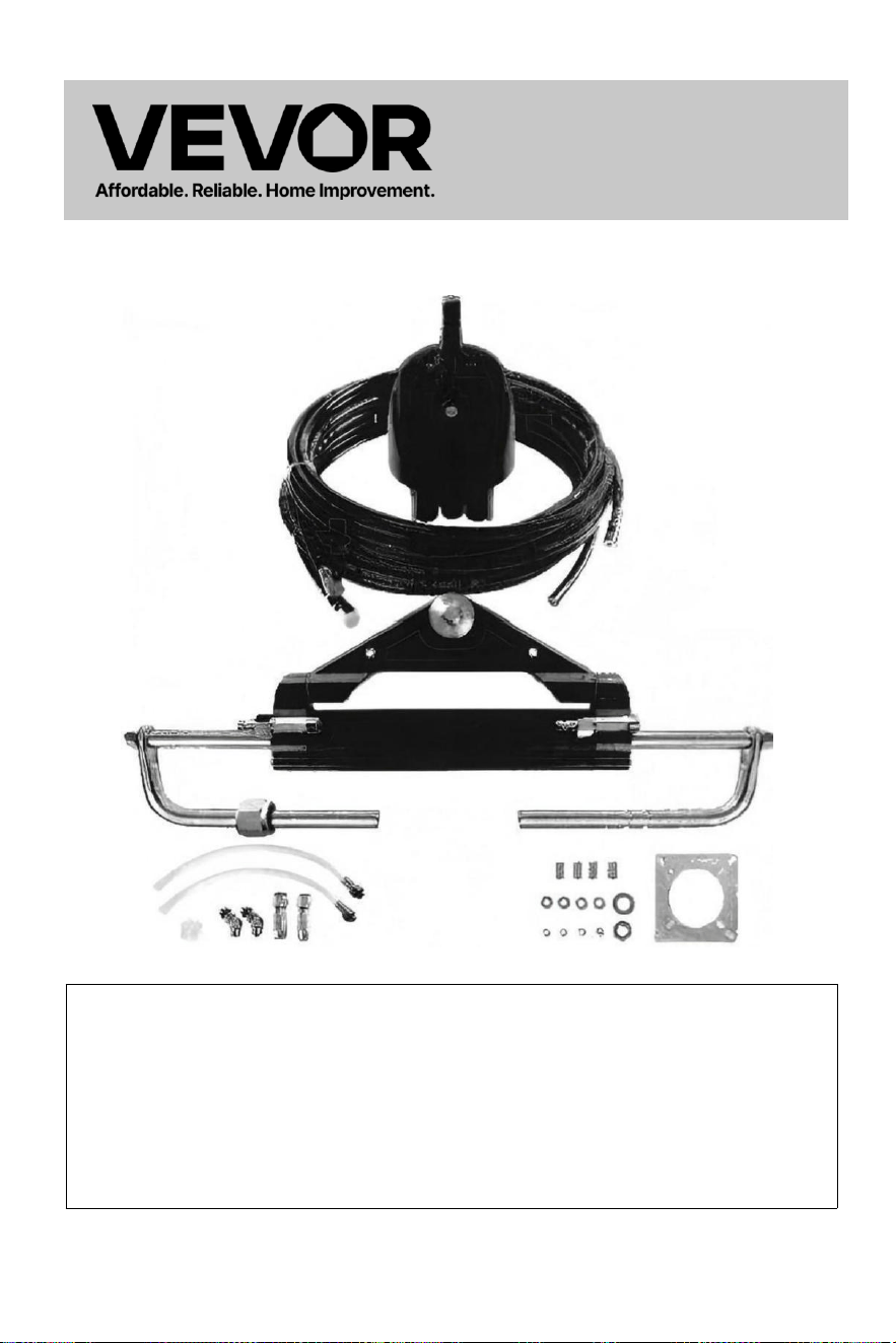
- 1 -
Dirección
hidráulic
a Para
Barcos
Modelo : YSH -150 HP
Este es el original instrucción, Por favor lea todo manual
instrucciones
con cuidado antes de operar. VEVOR se reserva el derecho de
interpretación de nuestro manual de usuario. La apariencia del
producto deberá ser sujeto al producto que usted recibió . Por favor,
perdónanos por no informarte nuevamente si hay alguna tecnología
o software actualizaciones sobre nuestro producto.
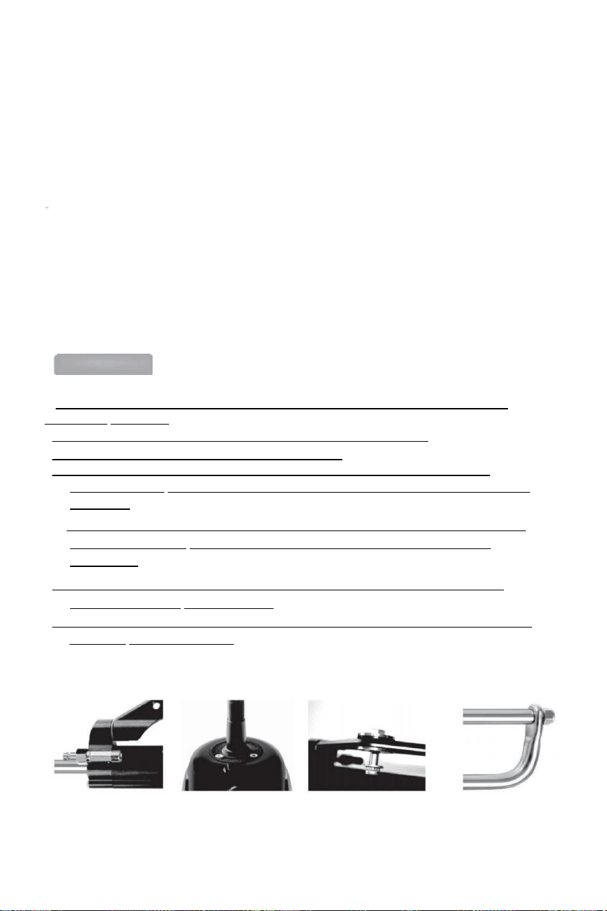
- 2 -
Gracias por adquirir el sistema de dirección hidráulica VEVOR.
Este manual explicará las distintas funciones de este sistema para que usted poder
Experimente plenamente el disfrute premium que este producto puede brindarle.
VEVOR hidráulico gobierno El sistema se basa en el concepto de industria moderna
diseño,el alto eficiencia, alta transmisión fuerza pistón bomba tecnología es aplicado
a el diseño y fabricación de mecanismo de gobierno del barco, lo que hace que su
gobierno sistema más estable, más inteligente y más confiable.
El principal componentes de el gobierno engranaje son alto fortaleza aluminio
aleación y acero inoxidable que se puede utilizar en duro condiciones marinas y
extender el
longevidad de m e c a n i s m o de dirección .
El gobierno engranaje voluntad aliviar tú de el pesado y inflexible mecánico eje
dirección, lo que puede salvarle los brazos doloridos. Puede mejorar el placer de
conducir un lancha rápida.
Main features:
● La dirección bomba Tiene una estructura interna compacta y un diseño moderno. y
hermoso apariencia .
●La válvula de bloqueo incorporada de dos vías elimina el par de rebote.
● Fácil de reemplazar el eje t sello, fácil de usar diseño ;
●Eje de dirección con especial superficie tratamiento no solo tiene fortaleza y
confiabilidad, pero también tiene el características de desgaste resistencia, corrosión
resistencia.
● Alta resistencia aluminio aleación caparazón y superficie tratamiento proceso poder
asegurar su desgaste y resistencia a la corrosión y prevenir la erosión hídrica
eficazmente.
● Tubería: Nailon de alta resistencia racores de tubo de 1/4 de montaje rápido hace la
instalación compacto y Es reutilizable .
●El usar de costumbre alto -estándar hidráulico aceite poder mejorar el lubricación de
regiones y protección del sello.

- 3 -
Normas generales de seguridad y garantía
Este manual de instalación y mantenimiento es parte integral parte de el producto y
debe ser completamente comprendido por el usuario antes de la instalación .
La instalación, mantenimiento y traslado de hidráulico dirección sistema
componentes de VEVOR serie de los productos deben ser hecho por el autorizado y
calificado profesional
técnicos.VEVOR serie de productos implementos el garantía para dos años s e r v i c i o
postventa ,cuando utilizando el producto,si hay alguna Si tiene alguna pregunta o
problema, comuníquese con el distribuidor. con el tiempo.VEVOR lo hará Proporcionar la
orientación correcta. VEVOR no se hará cargo responsable para las consecuencias del
desmontaje o desmontaje no autorizado.
Sin perjuicio de la naturaleza del producto, VEVOR se reserva el derecho de: derechos
a hacer cambios a el descripción información y ilustraciones contenido en este
manual, VEVOR no asume ninguna responsabilidad por L a s consecuencias adversas
causadas por el afrontamiento este manual en cualquier otros medios ilegales lo que
hace el usuario no puede seguir el
de instalación estándar .
Instalación Precauciones:
● Usar componentes proporcionó por Solo VEVOR,El regiones s
suministrado por el otro los fabricantes pueden causa riesgos de seguridad
y afectar el gobierno función;
●En toda la tubería conexión hilos, solamente focas semejante como Loctite PST o
equivalente
Se debe utilizar sellador. No utilizar (bandas) o cintas de sellado similares, ya que esto
puede permitir escombros para entrar el cuerpo de la bomba y causa el bloqueo de la
tubería.
● Utilice números especiales de 10 o 15 Aceite hidráulico calificado y respetuoso con el medio
ambiente.
amigable. Usar otro aceite (como aceite de frenos) en su lugar puede causar daños
irreparables a su equipo, causando pérdida de dirección función y sin garantía.
●El radio de curvatura mínimo del La tubería mide 1"18 (30 cm). No toque la afilado
objetos. Doblar, frotar, rascar o continuar La torsión puede causar la tubería a ser
dañado y ruptura debido a la presión de dirección normal, lo que provoca la pérdida de
gobierno función.
●No deje que la tubería se caiga con libertad Al utilizarlo, utilice alambre u otro material de
PVC para arreglar,para que a evitar posibles riesgos de seguridad.
● Mantenimiento regular de Componentes del sistema e inspección de tuberías y
guarniciones para desgaste o daño puede prolongar la vida útil de su equipo.

- 4 -
Lista de embalaje:
Código
SKU
Modelo
Accesorios de embalaje
Alto-
presión
aceite tubo
longitud
YYZXDB150HP0
5UTKJ001V0
YSH-
150 CV
Bomba hidráulica*1
Placa de montaje*1
Manual de
instrucciones*1
Engrasador olla*1
Tubos de llenado de aceite*2
Conector de codo de 135
grados *2 Bujes de montaje *4
1/4 lavadora*4
1/4-20UNC nueces*4
5/8-18UNF *2
5/8 lavadora*2
0
YYZXXTTJ90HPI
VK97001V0
YSH-
90
caballos
Bomba hidráulica *1
Cilindro de dirección
hidráulica *1 Placa de
montaje *1
Conectores de codo de 135
grados *2 Conectores rápidos
*2
Bujes de montaje *4
1/4 lavadora*4
1/4-20UNC nueces*4
5/8-18UNF *2
5/8 lavadora*2
Transparente Manguera con
conector *2 Grasa plástica pezón *1
Manual de instrucciones *1
Engrasador *1
0
YYZXXTTJ90HP
DLO3P001V0
YSH-
90
caballos
Bomba hidráulica*1
Cilindro de dirección
hidráulica*1 Tuberías de
aceite de alta presión*2
Placa de montaje*1
Codos de 135
grados*2
Conectores
rápidos*2
Bujes de montaje*4
1/4 lavadora*4
1/4-20UNC nueces*4
5/8-18UNF *2
5/8
lavadora*2
Transparente mangueras con
conectores*2 Grasa plástica pezón
e*1
Instrucciones*1
Engrasador*1
20 pies
YYZXXTTJ90HP
WYCCR001V0
YSH-
90
caballos
24 pies
YYZXXTTJ150HI
HNTU001V0
YSH-
150 CV
20 pies
YYZXXTTJ150H
3TSCX001V0
YSH-
150 CV
24 pies
YYZXXTTJ150H
3E857001V0
YSH-
150 CV
26 pies
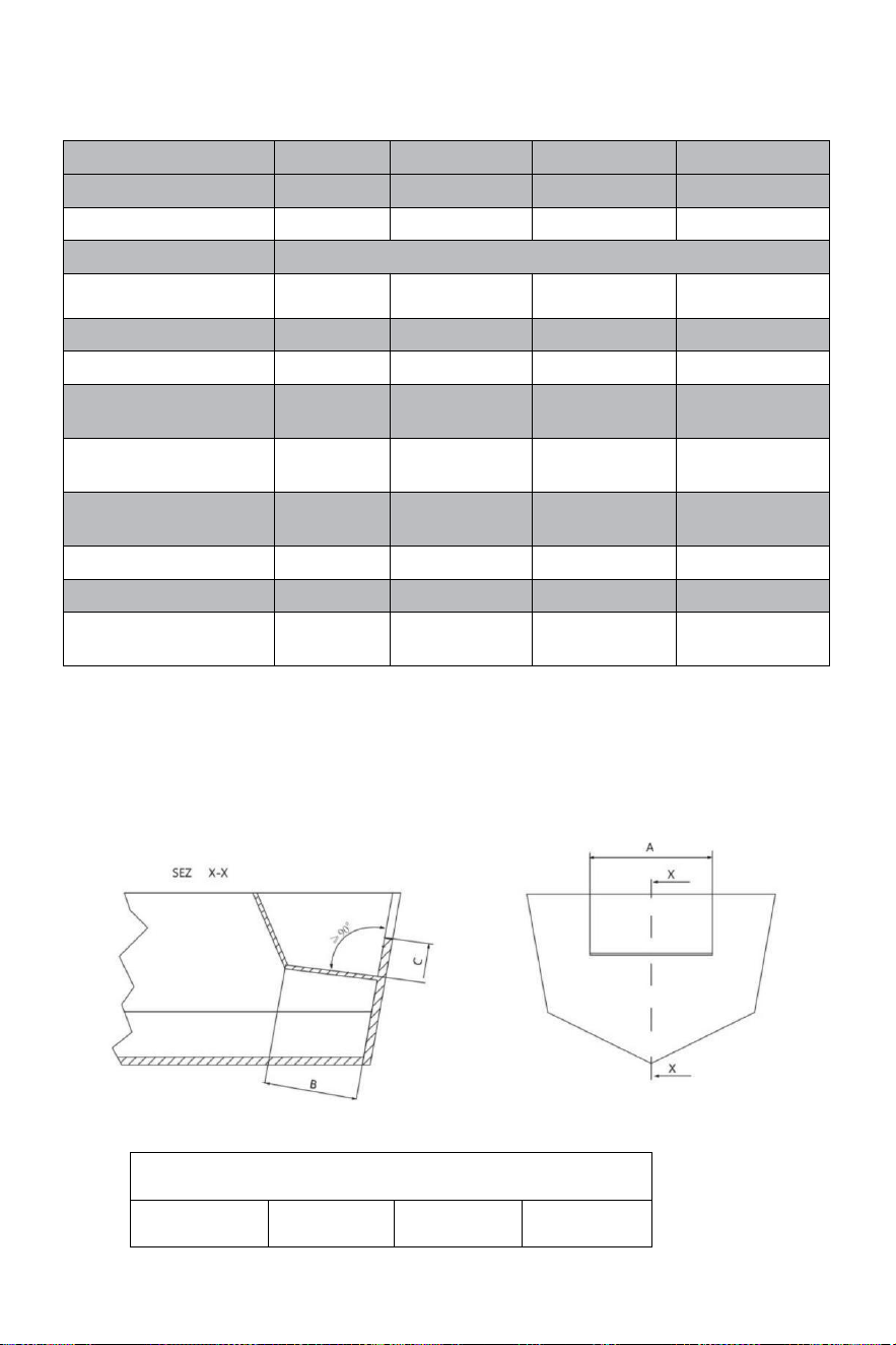
- 5 -
Técnico información:
TIPO
YSH-90HP
YSH-150HP
YSH-200HP
YSH-300HP-B
ZAPATILLAS
NR90
NR150
NR200
NR300
CAPACIDAD CM³
16
18
27
27
Rosca de la rueda
5/8"-18UNF
PRESIÓN MÁXIMA
VERJA
69
69
69
69
VUELTAS DE RUEDA
5
5.5
6
7
CILINDROS
MR90
MR150
MR200
MR300-B
TUBO
Identificación[mm]
25
30
32
35
VARA
Identificación[mm]
14
16
16
18
FUERZA DE
SALIDA/KGF
232
400
470
470
CARRERA[mm]
200
198
200
200
VOLUMEN [cc]
67
101
125
142
SOLICITUD
Hasta
90 CV
Arriba a 150
CV
Arriba a 200
CV
Arriba a 300 CV
Dimensiones mínimas del pozo de salpicaduras:
Antes de intentar Instalación, asegúrese de que el pozo de salpicaduras de
su
bote tiene lo siguiente mini mamá dimensiones.
DIMENSIONES MÍNIMAS DEL POZO DE
SALPICADURAS
Número de
motors
A
B
do

- 6 -
1
560 mm -
21,25"
152 mm (5,98
pulgadas)
152 mm (5,98
pulgadas)
2
1110 mm -
21,55"
152 mm -
5,99"
152 mm -
5,99"
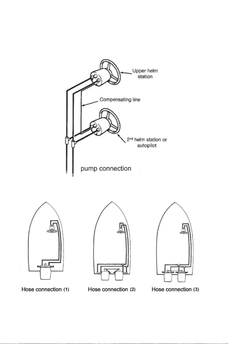
- 7 -
Instalación de mangueras/accesorios- conexión de
bomba
Referirse a A continuación se muestran ilustraciones para la correcta conexión de las mangueras .
timón bomba al cilindro.
Conexión de manguera
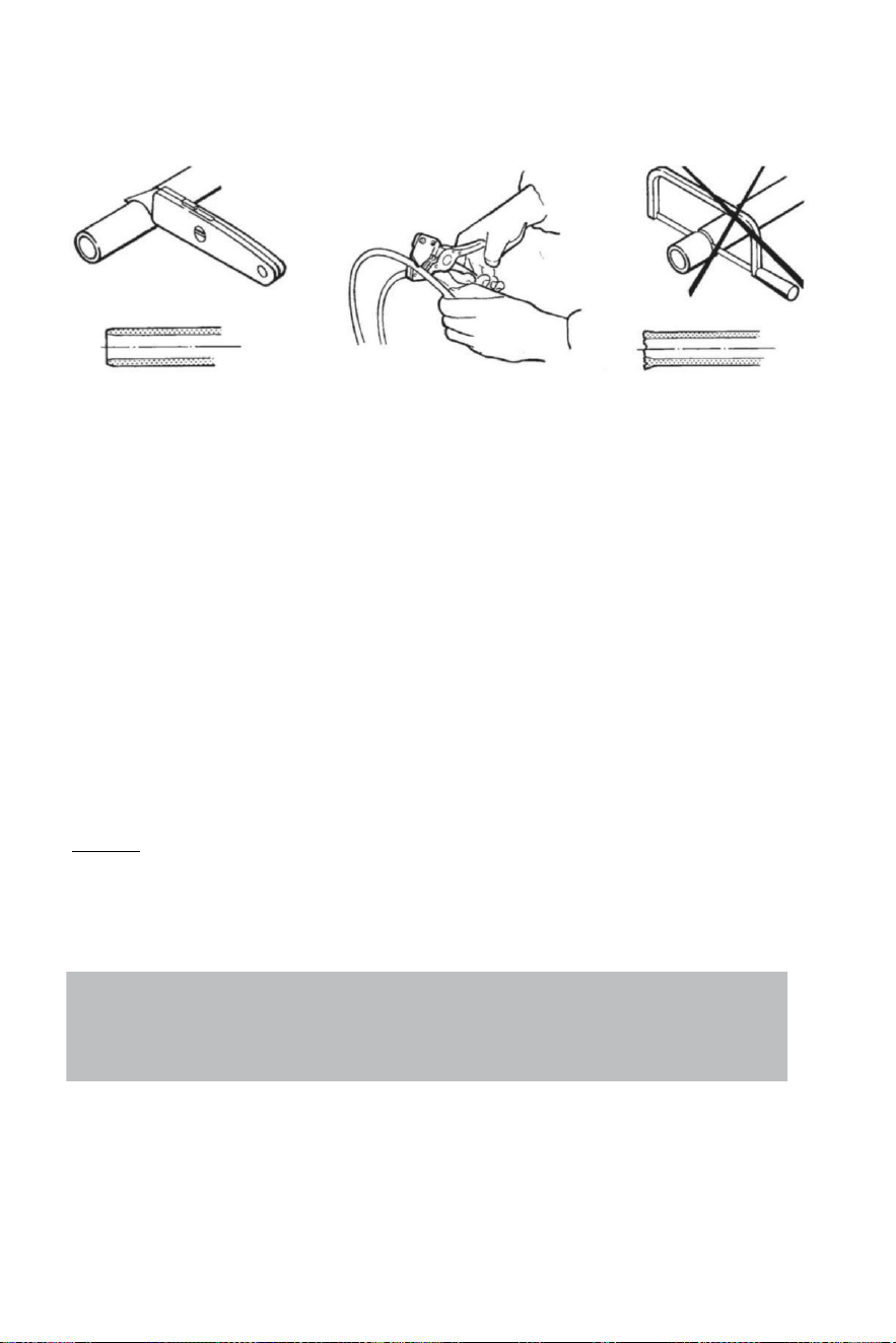
- 8 -
Conexión de manguera
Recomienda el usar de VEVOR gobierno mangueras solo.
Siempre intentar a ruta el mangueras a través de el más corto camino en orden a evitar
cualquier posible pérdida de poder.En Orden para hacer el aire sangría del sistema Más fácil, es
sugerido montar las mangueras
horizontalmente con un inclinación de acerca de 3 centímetro por metro;el bomba lado tiene a
ser más alto que el cilindro lado.
Siempre proteger el mangueras eso tener a aprobar a través de a diferente compartimento t o
usar adecuado conectores de mamparo o manga s .
Manguera tener a ser instalado en semejante a forma ellos no representar un obstáculo para
otro componentes.
Hacer no eliminar protector fin cubiertas hasta el mangueras tener estado enrutado y son
listo a ser conectado a La bomba del timón p, conexión de la manguera o cilindro(s) de
dirección.
Proporcionar suficiente manguera longitudes a permitir para cilindro movimiento a lo largo de
el torneado arco y arriba/abajo ajustes de ajuste/inclinación de el motor(es).
A lo largo de el manguera instalación,asegurarse el protector gorras permanecer instalado
sobre el fin de el mangueras.
Atención:
Hacer no instalar mangueras en un área dónde ellos voluntad ser expuesto a alto calor .
extremo calor Reduce la presión de ruptura de la manguera y puede provocar que la manguera
derretimiento. Ejercite una gran limpieza . Haga seguro eso tubería y mangueras son
perfectamente limpio y gratis de viruta.
Note:
Flexible hoses have to be cut by means of a sharp knife;
never use a saw,as fragments of nylon in the hydraulic system cause serious problems.
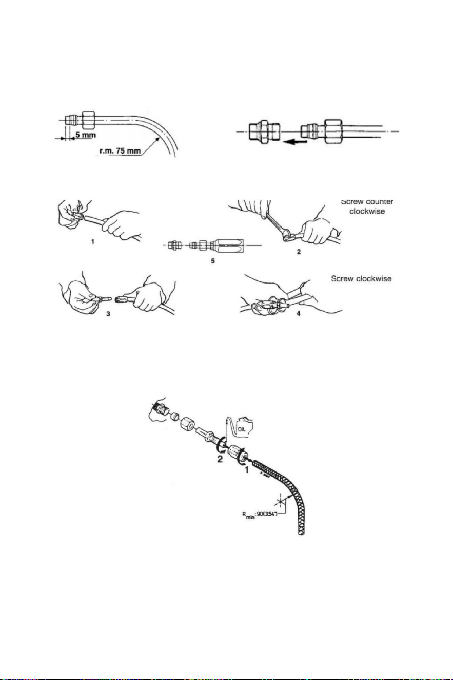
- 9 -
Instalación de mangueras hidráulicas
Después de cortar el nailon manguera, ajuste la enganche nuez y el apoyo manga en la
manguera(comprobar él es apropiadamente en relación con el fin del manguera).Después de la
montaje del nuez , tu tener a ajustado por medio de una llave.
De lo contrario , tú poder montar Manguera flexible de nailon con accesorios recuperables.Haga
lo que ilustraciones a continuación espectáculo.
Después el instalación limpio el adentro de el mangueras por soplo a través de usando
comprimido aire , en orden a evitar cualquier obstrucciones y a eliminar polvo y escombros
de almacenamiento.Antes el sangrado de aire él es también sugerido a hacer a enjuague de
el sistema . Hacer no usar agua .
1 Después de cortar, atornille el acoplamiento de tubo manga sobre el tubo (para zurdos) hilo).
2 Engrase el acoplamiento del tubo y tornillo Colóquelo en la manga.Hágalo seguro eso el
revestimiento interno de
la dosis del tubo
No seguir mientras se aprieta el ¡tornillo!También
asegúrate eso el interno
revestimiento de el tubería es no exprimido mientras apriete el tornillo .
3 Comprobar allá es No interno interferencia puesta a pequeño destornillador en el tubo
acoplamiento antes Proceder a la instalación de la manguera al timón o cilindro
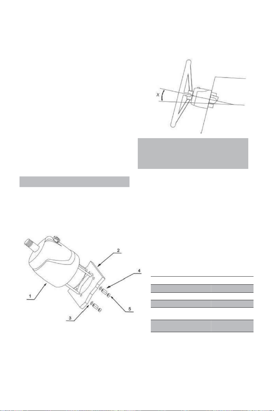
- 10 -
Sistema de dirección hidráulica YSH-150HP
Herramientas de instalación (Para completar el instalación de
este sistema , tú Necesitará las siguientes herramientas):
. Agujero sierra con 3 . 03 " (77 mm )
diámetro · 0 . 354 " (9 mm ) perforar poco
· 1 . 181 " (30 mm ) montaje llave inglesa
· 0 .433 " ( 11 mm ) instalación llave inglesa
· 0 .748 " ( 19 mm ) instalación llave inglesa
· 0 .669 " ( 17 mm ) instalación llave inglesa
· 0 .472 " ( 12 mm ) instalación llave inglesa
· 0 .945 " (24 mm ) enchufe llave inglesa
Important:
perform the bleeding procedure manually
and with the helm pump inclined no
more of 10(X).
Steering pump YSH-150HP Installation:
·Determinar el ángulo y posicionarte están instalando en asegurar eso el volante hace no
interferir con otros equipos. Compruebe que haya todavía suficiente espacio detrás el
puente Tablero de instrumentos (2) para montaje y conexiones de tuberías.
RIF.
CANTIDAD
DESCRIPCIÓN
1
1
bomba
2
1
Junta
3
4
Calce
4
4
Tuerca de
extensión
5
4
Cerrar
tuerca
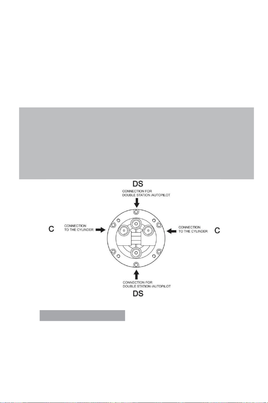
- 11 -
·Adjuntar a1:1 acceso agujero montaje plantilla (incluida) con este ma nual)a el instrumento
panel,y posicionar el montaje agujero de serie con un cortador de agujeros.
· Perforar un diámetro de 3,03" (77 mm ) agujero y perforar cuatro 0,354 (9 mm ) de diámetro
agujeros como mostrado en la plantilla de montaje.
·Ruta el organizado tubería a través de el medio 3,03" (77 mm) de diámetro agujero y conectar
él a la dirección bomba (1)
·Instalar el gobierno bomba en el instrumento panel con 4 arandelas(3)y 4 alivio de la lluvia
nueces(4),4 tuercas de seguridad (5), apriete par ≤15N.
·Lubricar el afilar sección del eje.Instalar el semicircular clave.Lugar el gobierno rueda en el eje
de dirección
y
el volante llave Adelante el semicircular clave.Lugar el calce y Apriete el gobierno
cerrar nuez . La apriete esfuerzo de torsión es ≤ 20 Newton .
Note:
·The steering pump should be mounted at a tilt angle of X≤20°.If it is exceeded,it
may cause air to enter the duct and affect the steering function.
·Only use self-locking fasteners provided by VEVOR or standard fasteners.Using non-self-
locking fasteners instead may cause the equipment to loosen or separate.
·Do not open the pump cover or filler cap when installing the steering pump to prevent dirt
and chips from entering the pump and causing the steering function.
·Teflon-like ribbon seals can not be used on pipe nipples,which may cause tape chips to enter
the pump body and thus affect the steering function.(The VEVOR series is a pipe thread
sealing technology that does not require the use of other sealing tape seals.)
VALVE PORTS CONNECTION:
Puerto marcado “C”: conexiones al/los cilindro/s
Puerto marcado “DS”: conexiones a la estación adicional o piloto automático
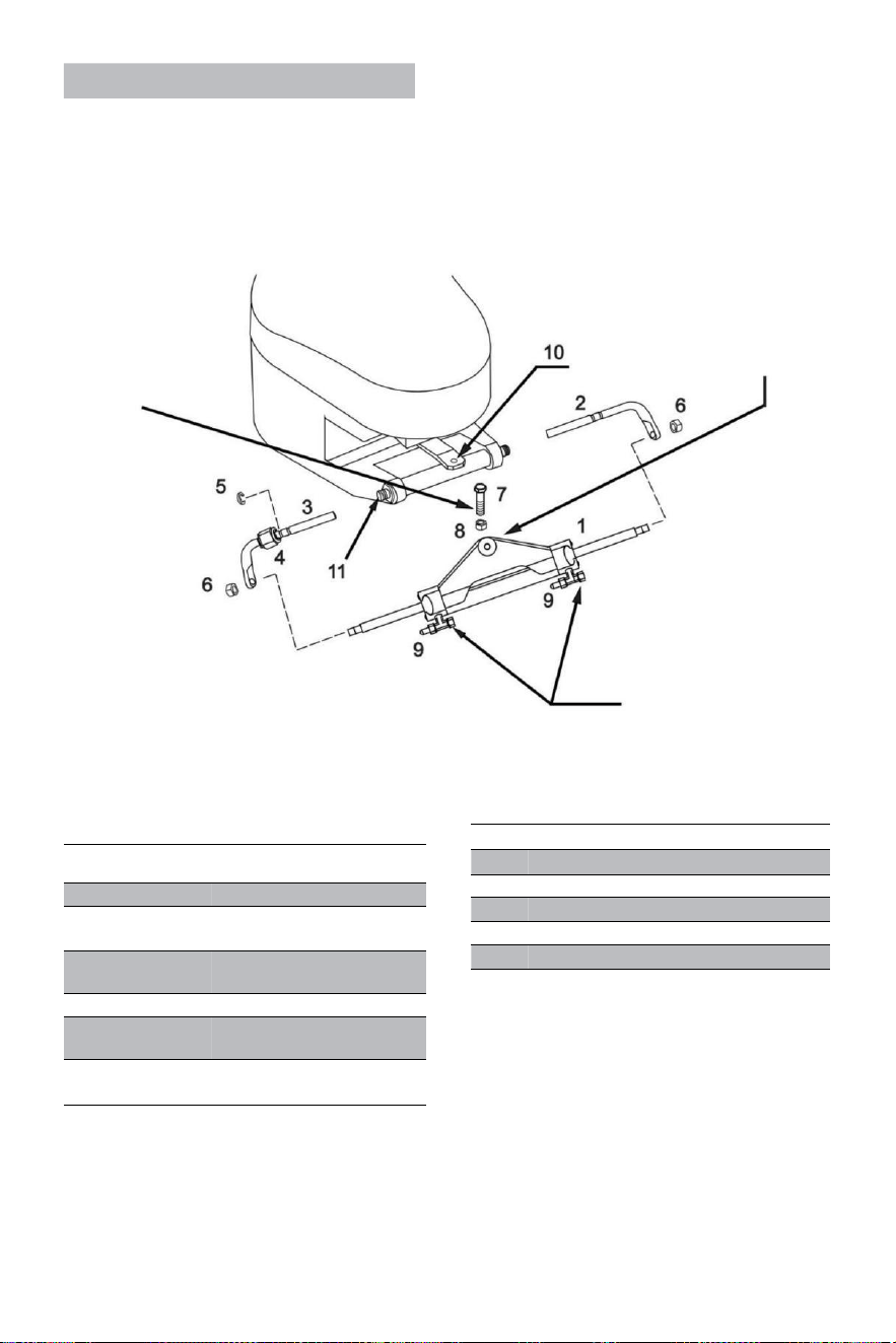
- 12 -
Cylinder YSH-150HP Installation:
ADVERTENCIA:
Él es importante a controlar
periódicamente , a las el
menos cada 3 meses (o
cada mes) para usos
profesionales),la bien
par de este perno y del
cerrar tuerca.
El brazo del cilindro debe
estar adjunto de el motor
caña del timón brazo en la
mayoría marcas
de motores fuera de borda
en el evento eso el caña
del timón interfiere con
otras partes de la fuera de
borda, entonces puede ser
montado bajo el timón en
cambio.
ADVERTENCIA:
Retire las tapas rojas en
orden a instalar el
manguera accesorios .
Desis
te .
CANTIDAD
DESCRIPCIÓN
1
1
Cilindro
2
1
Apoyo adecuado
soportes
3
1
Soporte de izquierda
soportes
4
1
Conectando tuerca
5
1
Inoxidable hebilla de acero
(C)
6
2
Varilla del pistón cierre
tuerca
·Antes intentando a instalar, por favor comprobar si su El motor es adecuado para este
tipo del cilindro , y asegurar eso su popa junta espacio es de suficiente tamaño para
Instalación .
· Antes instalación , por favor lubricar el móvil conexión regiones de el motor y el
cilindro
y el pistón vara con marinos calificados lubricante ,y enderezar su motor a el medio posición;
RIF.
QUANTITY
DESCRIPTION
7
1
3/8 connecting bolt
8
1
3/8 Lock nut
9
2
Deflation device
10
1
Engine connecting block
11
1
Engine mounting hole
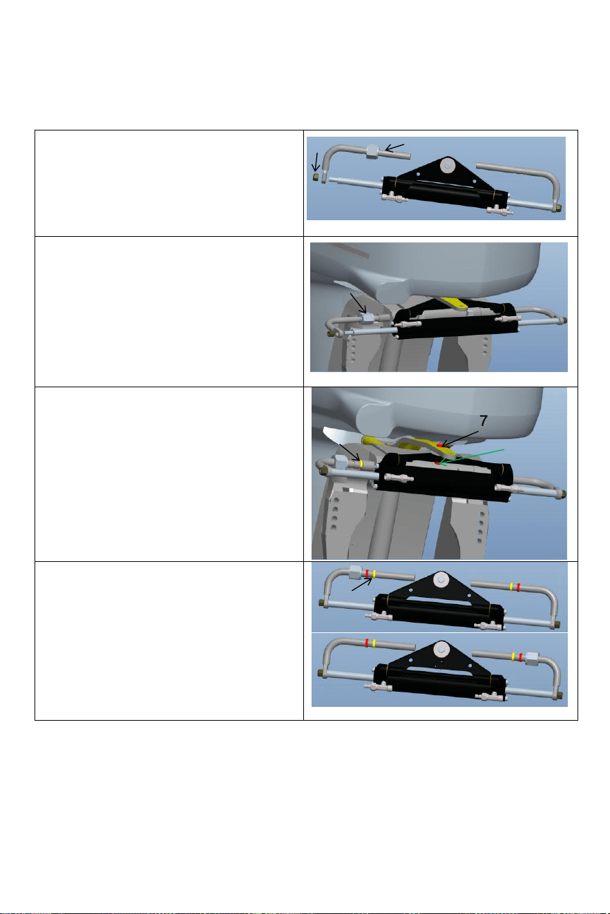
- 13 -
·
Afloje el autobloqueo tuerca(6)en un extremo del
cilindro pistón vara,y eliminar el instalación vara
(3).Después eliminando el piezas,instalarlas
instalación vara (3)en el motor instalación
agujero(como se muestra en la figura arriba);
Retire el perno (7) del medio agujero del
cilíndrico triángulo soporte soporte, ajustar El
ángulo del motor y arreglar el cilindro triángulo
soporte a el motor con perno(7)y tuerca(8)
correspondiente a el agujero en la placa de
conexión del motor.Preste atención a el swing de
izquierda a derecha de el máquina a asegurar
eso el cilindro voluntad no interferir con el
movimiento de el motor después instalación.
Ajustar el motor Ángulo y cilindro pistón vara
extensión longitud.Según a el brecha entre El
motor y el cilindro correctamente Instalar el
inoxidable acero Abrazadera en C (5) en el
adecuado ranura del montaje vara.(Ver cifra
arriba)
6
3
4
5
7
8
5
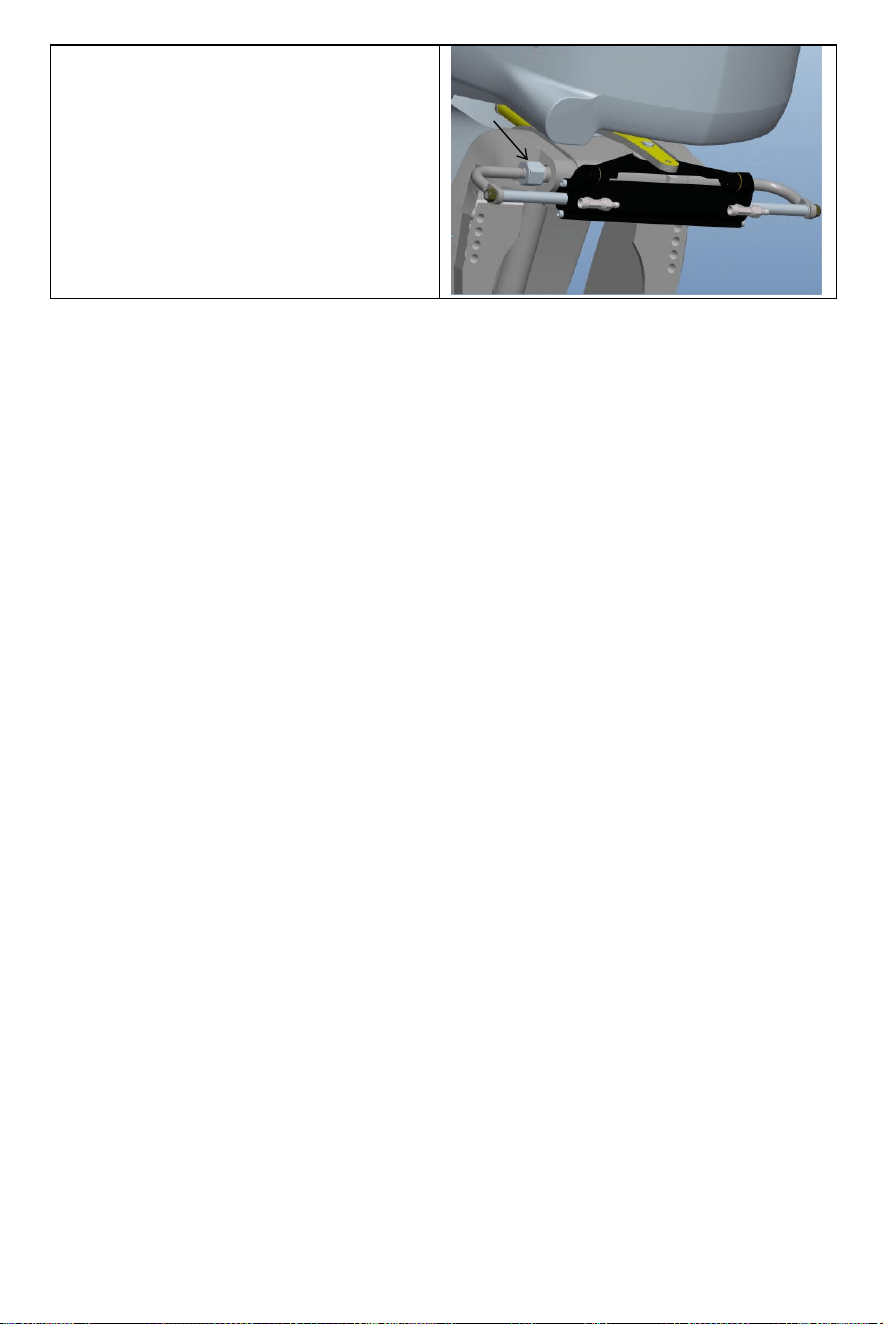
- 14 -
Después de la instalación, la tuerca de bloqueo (4)
debe estar apretado a eliminar el operante
autorización del cilindro. Esto mejorará su
experiencia.
4

- 15 -
· Después el instalación es completar , empujar su motor a el izquierda y bien a hacer a
ensayo correr del cilindro. Compruebe si hay piezas que interfieren cuando el cilindro funciona. de
ida y vuelta . Si allá es interferencia , tu necesidad a reajustar el instalación . Si allá es No
interferencia , empuje el motor a el fin de el izquierda / derecha límite . El próximo paso es
a repostar y escape;
· Conectar el organizado aceite tubería a el aceite tubo articulaciones (2) en secuencia , bloqueo
el sangrar
articulaciones(3) del cilindro Para preparar para el próximo abastecimiento de combustible y
agotador pasos para instalar el sistema.
Warning:
When installing,to avoid bumping the piston rod,it is forbidden to hit the piston rod with wrench or
anything hard.If the piston rod is bruised,it will cause hydraulic oil leakage of the oil cylinder,
which will compromise your product experience.
Dirección hidráulica VEVORel sistema deescape de gas:
Este El procedimiento de trabajo requiere dos personas para operar,una persona puede no ser
capaz de eliminar por completo todo el aire adentro el hidráulico sistema cual resultados en
eso el hidráulico salida del sistema presión es No es suficiente, el impacto de la debilidad es
nuestra debilidad, respuesta lenta, por lo tanto
afectando su experiencia con el producto.
Por favor utilice especial
A c e i t e
hidráulico ecológico proporcionado por VEVOR o otro especial
calificado
hidráulico Aceite para repostar. No utilizar aceite de freno.Usando otros corrosivos inaceptables
el aceite puede causa daños irreparables a su sistema y resultado en el producto ser
incapaz a ser
justificado.

- 16 -
Precautions:
·If you fill the pump with hydraulic fluid before connecting the filler tube to the pump,the
filling procedure can be made more quickly and easily.
·In case of emergency,any non-toxic,non-corrosive,non-flammable oil can be temporarily
supplied to the system,but the entire system must be thoroughly cleaned afterwards;
·Please keep refueling tube visible during the entire refueling process.Do not allow oil to
enter the pump. Otherwise,air may be introduced to increase refueling time.
·During the process of refueling and exhausting,the hydraulic oil collected from the air
bleeder manifold of the cylinder can be used directly after a few moments.
·Please protect the environment and properly dispose of used oil.The special hydraulic
oil provided by VEVOR system can be reused after being filtered by the filter with the hole
diameter less than or equal to 38um.
Los asuntos necesitan atención
Nota 1 Utilice el especificado Vi s c o sid a d 20 #-32# de hidráulico aceite, hacer no usar diferente
tipos de hidráulico aceite con diferente viscosidad, d o no mezcla hidráulica aceite con cualquier
desconocido líquido.
Nota 2 Hacer no usar impuro aceite hidráulico, impuro El aceite hidráulico causa hidráulico
bomba falla y ruido.
Nota 3 Añadir aceite hidráulico al hidráulico bomba en el relleno especificado puerto a evitar
mezclando agua o impurezas. El aceite hidráulico debe ser mantenido en estado de aceite
completo en el hidráulico bomba.
Nota 4 Al agregar
aceite
hidráulico , Debería ser filtrado con a filtrar pantalla. No bien
contaminantes de más De 5 μm a 10 μm pueden entrar en el aceite bomba, que voluntad causa
regiones bloqueo, ruido, dirección traspuesta válvula morder, y hacer el aceite bomba fallar.
Nota 5 Debería haber ser No burbujas en el aceite hidráulico, que aumentar el ruido del hidráulico
bomba y causa (causa Fallo desconocido. Burbujas de aire . debe ser descargado. Por favor referirse
a páginas 11 y 12 del Manual para la operación específica del escape métodos
Nota 6 En el proceso de usar, él es necesario a controlar regularmente si allá es aceite fuga ge
en el bomba cuerpo, aceite tubería y aceite cilindro y tratar con él en tiempo .
Volante del Note 7 el juego puede ser resuelto mediante la aplicación presión a el gobierno rueda. El
procedimiento es como sigue: gira el volante en el sentido de las agujas del reloj para llenar cerrar
con llave. Continuar torneado el gobierno rueda hasta que te sientas importante resistencia.
Entonces desenroscar el tapón de llenado de combustible tapa y continuar relleno el combustible
Bomba con aceite. Apriete el tapón de llenado de combustible. y el dirección rueda jugar voluntad
ser eliminado.
Nota 8 Al llenar el aceite bomba con aceite, por favor utilizar el aceite relleno boquilla
proporcionó por a nosotros, cual es Equipado con un filtro de aceite sh de 60 me a filtrar afuera
impurezas en el aceite.
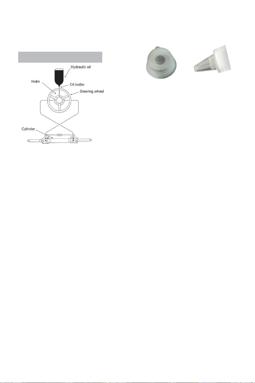
- 17 -
Refueling and Venting Steps:
·Atornille la rosca del tubo de filete . equipado con el sistema
en el puerto de la bomba de combustible y apriete para confirmar que esté hermético.
·Adaptar el monte afilado incluido con este sistema a el
aceite tapa de botella.Insertar el boca afilada en la
bomba
Con algo de fuerza, vierta el aceite en el tubo de llenado de
combustible.
hasta que no puedas ver el aire botella poder ser
exprimido suavemente a velocidad arriba repostaje.)
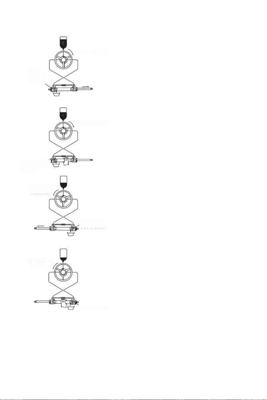
- 18 -
(parameter table)to determine whether the hydraulic
Turn clockwise
Open
left side
bleeder
Turn clockwise
Close left side
bleeder
Turn counter
clockwise
Open right
side bleeder
Turn counter
clockwise
·Doblar la dirección rueda lentamente en el
sentido de las agujas del reloj hasta un
lado de la pistón vara está completamente
extendido.Ajuste el tubo de escape a la
retracción lado del pistón vara a recolectar
el aceite de desfogue.
·Sostener el cilindro a prevenir el cilindro de
torneado, destornillar el desinflado en el pezón n
ested en el
lado de el purgador,(no desenroscar
él completamente,lo es suficiente si
tú poder ver el aceite)girar el gobierno
rueda en el sentido de las agujas del reloj
hasta tú ver el adentro del
escape tubo Expulsado
aceite es estable y minucioso , no burbujas ,
girar el volante en el mismo tiempo apretar el
tuerca de desinflado Ajustes de escape estrechos ;
·Continuar a doblar el gobierno rueda
en sentido contrario a las agujas del reloj hasta
que retractación original lado de El vástago
del pistón está completamente extendido,
ajuste el escape tubo a el retraer
lado del pistón vara a recolectar el aceite
de desfogue
·Sujete el cilindro Para prevenir el cilindro
de girar, Desenroscar la tuerca de la junta de
desinflado de uno lado.(No destornillar Está
completamente , está bien. suficiente como
largo como tú poder ver el
aceite).Girar el gobierno rueda en el sentido de
las agujas del reloj hasta que ver el aceite de el
La tubería de desinflado es estable, no burbujas,
apriete el hemofílico bloquear, cerrar
deflación dispositivos.
·Gire el volante en sentido horario/antihorario.
varios veces a controlar el número de giros completos
del timón
fluido en el tubo tiene estado completamente
excluido.Si
hay aún aire,el numero de timón completo aumentará .)
si allá es aún a lote de aire que es no excluido,
entonces repetir
procedimiento (3)~(6). Si allá es a pequeño cantidad
de aire , hacer
lleno timón en uno directo, inverso pequeño s emi
círculo,hacer lleno
timón de nuevo,hacer este para 5-6 veces para la
dirección izquierda
y bien dirección.
Close right side
bleeder

- 19 -
·Después alrededor timón prueba pasar,r
quitar el combustible tubo y tubo de purga,
tornillo el combustible gorra, conjunto el
desinflado conector manga,la no usado
hidráulico aceite es cerrado para posterior
Mantenimiento y reparación.(Verificar el
sistema hidráulico) bomba aceite
superficie una vez cuarto, insuficiente aceite
voluntad causa
algo anormal.)

- 20 -
Fallas y soluciones:
El siguiente son el mayoría común fracasos y su causas y soluciones .
Cuando el timón gira con lleno timón (cilindro lleno) accidente cerebrovascular ), allí tal
vez leve resistencia y interno sonido de clic de las piezas que es de válvula interna piscina
s pelota y cojinete acero pelota Cuando ellos son correr.
Es normal fenómenos. Por favor hacer no pensar él es causado por fallas.
FALLA CAUSA SOLUCIÓN
El hidráulico timón es
completamente atascado
durante instalación.
Tubo bloqueo entre el
hidráulico bomba y
cilindro hidráulico.
Comprueba si el manguera tubo es
obstruido o doblado, si es así es
doblado, debes reemplazar la
manguera dañada,o Puede ser
resultado en el pérdida de gobierno y
grave lesiones personales o propiedad
daño.
Él es difícil a repostar el
sistema, incluso cuando el
sistema dice el combustible es
lleno, burbujas continuar a
estallido afuera de el aceite
bomba.
·Allá es aire en el sistema
·Sangrar adecuado fugas
· Hidráulico pipping tiene
devanado o flexión lesiones
.Instalarel sistema adecuadamente de
acuerdo a hacia Manual deinstalación.El
entrada tubo debe ser siempre hacia
arriba.
·Apretar el deflación guarniciones.
·Relajarse y recto el
manguera o reemplazar el
dañado manguera.
Cuando usando el sistema
a Dirigir, necesitas a girar el
timón completo rápidamente
para muchos veces.
·Hidráulico pipping tiene
doblado lesiones
·Allá es gas o bien burbujas en
el hidráulico aceite.
· Hidráulica incorrecta aceite
Fuimosnosotrosed
·Relajarse y enderezar el
manguera o reemplazar el dañado
manguera.
·Repostar o escape adecuadamente
según el manual de instalación .
·Usar el correcto hidráulica aceite
Cuando el sistema es
lleno timón,el gobierno
rueda justo no trabajar.
Hay suciedad impurezas en
el hidráulico bomba
válvula
·No usar el sellado de "banda" cinta en
el interfaz.
·Llevar aparte el hidráulico bomba a
limpio el suciedad.
El El sistema puede buey
el barco fácilmente cuando el
barco es estacionario,Sin
embargo, él es muy difícil
a buey mientras navegación.
·Volante pequeño era
seleccionado.
·Motor conexión es no
colocar correctamente,
.Bolsa de aire es generado en
el sistema y aire no es
excluidos completamente.
·Sistema configuraciones
superar fuerza límites.
·Cambiar a a más grande dirección
rueda de cual el máximo diámetro
es sin excesivo 56 centímetros.
·Ajustar el motor conectar ion
ajustes correctamente.
·Verifique el aceite superficie de
hidráulica bomba, reiniciar el repostaje y
ventilación correctamente.
Volante vueltas a
izquierda puerto lado,
Barco gira a la derecha
Aceite equivocado tubo conexión
Intercambialos dos aceite tubería de el
cilindro con entre sí y instalar a ellos.
Lata cilíndrica no ser
instalado a el motor.
Cada cilindro requiere
correspondiente motor modelo.
Por favor refiérase a el manual o
el servicio al cliente de el
distribuidor a cambiar el modelo.
Cuando el timón bomba alcanza el detener punto(cilindro lleno accidente cerebrovascular),a pequeño
cantidad de hidráulica deriva es normal y el timón bomba es no 100% bloqueado.

- 21 -
Mantenimiento
Advertencia:
Siguiente el rutina mantenimiento horarios como delineado abajo,en el periodo de tiempo voluntad
anotada asegurar años de servicio de su sistema de dirección VEVOR, así como mantener tú y
su pasajeros seguro de el
peligros que están presentes en y fuera del agua.
Falla a cumplir con mantenimiento cheques puede resultado norte pérdida de dirección,
causando propiedad daños y/o personal lesión.
Las inspecciones son necesarias cada año y debe ser transportado afuera por especializado
marina mecánica. Controlar el eje y el o anillos del cilindro,el o anillos del timón bomba,la
accesorios del
cilindro y bomba de timón en Ordenar a prevenir Fugas.
Controlar opresión de todo sujetadores / accesorios a lo largo de el dirección sistema.
Limpiar el sistema usando agua dulce y no abrasivo líquido.
Limpieza fluidos que contiene amoníaco, ácidos o cualquier otro corrosivo ingredientes
debe no ser usado para limpieza de cualquier regiones del hidráulica c gobierno sistema.
HACER no usar freno aceites o automático transmisión fluido(ATE).Uso solo compatible
hidráulico aceites.
Previo a cada usar:
· Controlar Líquido nivel en más alto timón bomba
·Verificar de inmediato respuesta de la dirección cuando torneado gobierno
rueda(s) (Asegúrese de motor vueltas cuando dirección la rueda es transformado).
· Visualmente inspeccionar todo gobierno mangueras y ajustes para desgaste , torceduras
y / o fugas .
·Comprobar si están atascados, sueltos o desgastados. o Fugas en la dirección componentes.
Advertencia:
HACER NO funcionar bote Si alguno componente es no en funcionamiento correcto condición .
En este caso,por favor llevar fotos inmediatamente y contacto su distribuidor.
Después primero 20 horas , entonces cada 100 horas o 6 meses a partir de entonces ( que alguna
vez llega primero ):
· Todo agujas anotado arriba
·Controlar opresión de TODO sujetadores /accesorios a lo largo de el dirección
sistema.Apretar a correcto Se requieren especificaciones de torque .
·Controlar para juego mecánico o agua sucia a lo largo de gobierno sistema ,correcto según sea
necesario.
·Controlar para señales de corrosión.Si H a y corrosión presente contacto su distribuidor.
Después cada 200 horas o 12 meses ( que alguna vez llega primero ):
· Todo agujas anotado arriba .
·Eliminar apoyo vara de motor dirección/inclinación tubo.Limpiar motor dirección /inclinación
tubo y reengrasar usando un bien calidad marina grasa.
·Varilla de soporte de grasa liberalmente.
·Grasa todo contacto agujas mostrado en el cilindro y atar bar instalaciones.
HACER NO quitar el timón perno a volver a engrasar.
·Eliminar volante y reengrasar rueda eje usando a bien calidad marina grasa.
· Inspeccione el aceite hidráulico para verificar su limpieza y enjuague. si es necesario.
Cualquier trabajo ser realizado con el sistema de dirección DEBE ser terminado por un
calificado mecánico con el trabajo conocimiento del sistema.
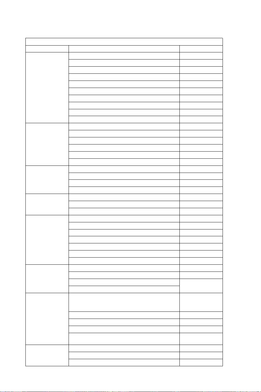
- 22 -
Fósforo la lista
SISTEMA DE DIRECCIÓN HIDRÁULICA HASTA 150 HP
MOTOR
FUERZA
AÑO
Yamaha
60-702 Accidente cerebrovascular
1990-2008
75C-902 Carrera
1998-2008
F70 4 tiempos
2010-hoy
115C-130B 2 Ataque
1990-2008
150 °F
1996-2007
150 HPDI VMAX de 2 tiempos
2000-2008
F75-F80 EFI 4 tiempos
1999-2007
F100-F115-F150 EFI 4 tiempos
1999-2007
F80-F100 4 tiempos
2000-hoy
F115-F150
2004-hoy
Honda
BF80-BF90 4 tiempos
1995-hoy
BF115D
1998-2009
BF115A
2009-hoy
BF130A
1998-2005
Carrera BF135-BF1504
2005-hoy
BF90-BF150V-TEC 4 tiempos
2008-hoy
Suzuki
DF70-80-904 Carrera
1998-hoy
DF100-115-1404 Carrera"
1998-2008
DF100-115-1404 Carrera nueva modelo
2008-hoy
DF 1504 Accidente cerebrovascular
2006-hoy
Tohatsu
Nissan
70-902 Accidente cerebrovascular
2004-hoy
115-120-1402 Accidente cerebrovascular
2004-hoy
90-90-115TLD 4 tiempos
2004-2011
Mercurio
Marinero
75-90 2 Ataque
1990-2008
115-125-150 EFI 2 tiempos
1990-2007
90-115-125 Optimax 2 Ataque
2004-hoy
135-150 Optimax 2 Ataque
1999-hoy
80-90 EFI 4 tiempos
2000-hoy
100-115 EFI 4 tiempos
2007-hoy
150 Cuatro tiempos 4 tiempos
2011-hoy
Evinrude
Carrera E50-E55-E602
2004-hoy
E75-E902 Accidente cerebrovascular
2004-hoy
E115-E130-E1352 Carrera V4
1995-hoy
1995-hoy
E1502 Carrera V6
Selva
50-Madeira/Tiburón toro-60 Tiburón
gris/ St. Tropez-70 Mako Shark de 2
tiempos
1996-2008
80 Portofino Tigershark 2 Ataque
1995-2008
150 Tiburón blanco 2 Ataque
2001-2007
50-60 Dorado EFI 4 tiempos
2001-2007
100 EFI Marlin -115 EFINarval-150
EFI Orca de 4 tiempos
2000-hoy
Johnson
Carrera BJ60-704
2001-2007
BJ90-115-140 4 tiempos
2001-2007
J90-115V4 2 tiempos
1995-2007
- 23 -
Advertencia-Para reducir la riesgo de lesiones para el usuario
debe leer instrucciones Lea el manual con atención.
Fabricante: Shanghaimuxinmuyeyouxiangongsi
Dirección: Shuangchenglu 803nong11hao1602A-1609shi,
baoshanqu, shanghai 200000 CN.
Importado a AUS: SIHAO PTY LTD. 1 ROKEVA STREET,
EASTWOOD, NSW 2122, Australia
Importado a EE. UU.: Sanven Technology Ltd. Suite 250,
9166 AnaheimPlace, Rancho Cucamonga, CA 91730
REP
UK
YH CONSULTING LIMITED. C/O YH Consulting
Limited Office 147, Centurion House, London
Road, Staines-upon-Thames, Surrey, TW18 4AX
REP
EC
E-CrossStu GmbH
Mainzer Landstr.69,
60329 Frankfurt am Main.

- 24 -
Hydrauliczny układ
kierowniczy Do łodzi
Model : YSH -150 KM
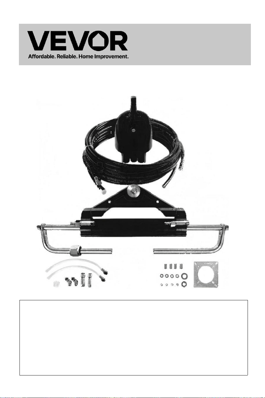
- 1 -
Hydrauliczny
układ
kierownic
zy Dla
Łodzie
Model : YSH -150 KM
To jest oryginał instrukcja, proszę przeczytać wszystko podręcznik
instrukcje
przed użyciem należy zachować ostrożność. VEVOR zastrzega
sobie prawo do wyraźnego interpretacja naszej instrukcji obsługi.
Wygląd produktu powinien Być temat do produktu, który otrzymane .
Prosimy o wybaczenie, że nie poinformujemy Cię ponownie, jeśli
pojawi się jakaś technologia lub oprogramowanie aktualizacje na
naszym produkt.
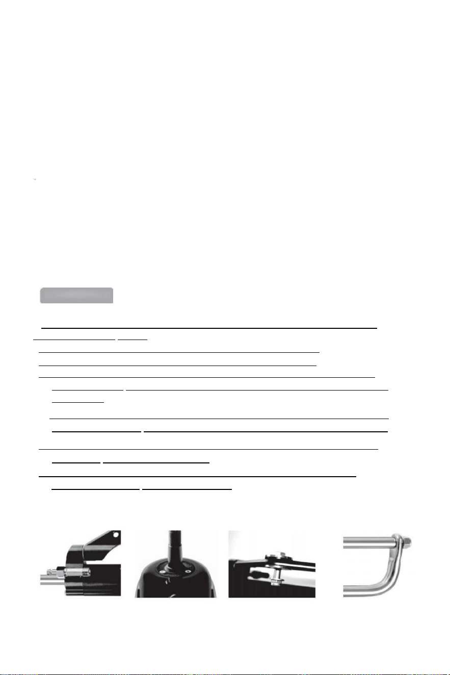
- 2 -
Dziękujemy za zakup hydraulicznego układu kierowniczego VEVOR.
W niniejszej instrukcji szczegółowo opisano różne funkcje tego systemu, aby ułatwić Ci
korzystanie z niego. Móc doświadcz w pełni najwyższej jakości przyjemności, jaką może Ci
zapewnić ten produkt.
VEVOR hydrauliczny sterowniczy system jest oparty NA koncepcja z nowoczesny
przemysł
projekt, ten wysoki wydajność, wysoka przenoszenie moc tłok pompa technologia
Jest stosowany Do ten projekt i produkcja urządzenie sterowe statku, które sprawia,
że sterowniczy system bardziej stabilny, inteligentniejszy i bardziej niezawodny.
Główny komponenty z ten sterowniczy bieg Czy wysoki wytrzymałość aluminium
stop I stal nierdzewna, która może być stosowana w szorstki warunki morskie I
rozszerzyć
długowieczność u k ł a d kierowniczy .
Ten sterowniczy bieg będzie łagodzić : uśmierzać Ty z ten ciężki I nieelastyczny
mechaniczny wał układ kierowniczy, który może oszczędzić Twoje obolałe ramiona.
Może zwiększyć przyjemność z jazdy łódź motorowa.
Main features:
● Układ kierowniczy pompa charakteryzuje się kompaktową konstrukcją wewnętrzną i
modnym I Piękny wygląd .
●Wbudowany zawór blokujący dwukierunkowy eliminuje moment odbicia.
● Łatwe do wymiany wał t uszczelka, przyjazna dla użytkownika projekt ;
●Wał kierowniczy z specjalny powierzchnia leczenie nie tylko ma wytrzymałość I
niezawodność, ale Również ma ten cechy charakterystyczne zużycia odporność na
korozję opór.
● Wysoka wytrzymałość aluminium stop powłoka I powierzchnia leczenie proces Móc
zapewnić jego zużycie i odporność na korozję i zapobiegać erozji wodnej faktycznie.
● Rury: nylon o wysokiej wytrzymałości szybkozłączki 1/4-rurowe sprawia, że instalacja
kompaktowy I jest wielokrotnego użytku .
●Ten używać z zwyczaj wysoki -standard hydrauliczny olej il Móc poprawić ten
smarowanie z strony I ochrona uszczelnienia.

- 3 -
Ogólne zasady bezpieczeństwa i gwarancja
instrukcja instalacji i konserwacji stanowi integralną część część produkt i musi być
w pełni zrozumiane przez użytkownika przed instalacją .
Instalacja, konserwacja i transfer hydrauliczny kierunek system
składniki VEVOR szereg z produkty muszą Być zrobione przez ten upoważniony I
wykwalifikowany profesjonalny
technicy.VEVOR szereg z produkty przybory ten gwarancja Do dwa lat serw i s
posprzedażowy , kiedy używając produkt, jeśli istnieje W razie pytań lub problemów
prosimy o kontakt ze sprzedawcą z czasem.VEVOR będzie zapewnić właściwe
wskazówki.VEVOR nie podejmie się tego zadania odpowiedzialny Do skutki
nieautoryzowanego demontażu lub rozmontowania.
Bez uszczerbku dla charakteru produktu, VEVOR ma prawo: prawa Do robić zmiany
Do ten opis informacje na temat I ilustracje zawierał W Ten instrukcja,VEVOR nie
ponosi żadnej odpowiedzialności za negatywne konsekwencje spowodowane radzeniem
sobie tej instrukcji w dowolnym inne nielegalne środki co sprawia, że użytkownik nie
może podążać ten
standardowa instalacja w instrukcji.
Instalacja Środki ostrożności:
● Używać komponenty pod warunkiem, że przez Tylko VEVOR, strony s
dostarczone przez ten Inny producenci mogą przyczyna zagrożenia
bezpieczeństwa I oddziaływać ten sterowniczy funkcjonować;
●Włączony wszystkie rury połączenie tylko wątki foki taki jak Loctite PST lub
równowartość
należy użyć środka uszczelniającego. Nie stosować (taśmy uszczelniające) lub podobne
taśmy uszczelniające, ponieważ może to umożliwić gruz wejść ciało z pompa I przyczyna
blokada z rura.
●Proszę użyć kodu 10# lub 15# specjalnego olej hydrauliczny, który jest kwalifikowany i
przyjazny dla środowiska
przyjazny. Zamiast tego użyj innego oleju (np. oleju hamulcowego) może spowodować
nieodwracalne uszkodzenia Do Twój sprzęt, powodując utratę sterowności funkcji i nie ma
gwarancji.
●Minimalny promień gięcia rura ma 1"18" (30 cm). Nie dotykaj ostry
przedmiotów. Ciągłe zginanie, pocieranie, drapanie lub skręcenie może spowodować rura
ma być
uszkodzony i pęknięcie z powodu Do normalne ciśnienie układu kierowniczego, powodując
w ten sposób utratę sterowniczy funkcjonować.
●Nie pozwól, aby rura spadła swobodnie podczas używania proszę używać drutu lub
innego materiału PCV do naprawić, tak jak Do uniknąć potencjalnego zagrożenia
bezpieczeństwa.
● Regularna konserwacja komponenty systemu i inspekcja rur I armatura Do nosić lub
szkoda może przedłużyć okres użytkowania z twój sprzęt.

- 4 -
Lista rzeczy do spakowania:
SKU
Model
Akcesoria do pakowania
Wysoki-
ciśnienie
olej rura
długość
YYZXDB150HP0
5UTKJ001V0
YSH-
150 KM
Pompa hydrauliczna*1
Płyta montażowa*1
Instrukcja obsługi*1
Olejarka garnek*1
Rurki do napełniania olejem*2
Łącznik kątowy 135 stopni *2
Tuleje montażowe *4
1/4 pralka*4
1/4-20UNC orzechy*4
5/8-18UNF *2
5/8 pralka*2
0
YYZXXTTJ90HPI
VK97001V0
YSH-
90 KM
Pompa hydrauliczna *1
Siłownik hydrauliczny układu
kierowniczego *1 Płyta
montażowa *1
Złącza łokciowe 135 stopni *2
Szybkozłącza *2
Tuleje montażowe *4
1/4 pralka*4
1/4-20UNC orzechy*4
5/8-18UNF *2
5/8 pralka*2
Przezroczysty wąż z przyłączem *2
Smar plastyczny sutek *1
Instrukcja obsługi *1
Olejarka *1
0
YYZXXTTJ90HP
DLO3P001V0
YSH-
90 KM
Pompa hydrauliczna*1
Siłownik hydrauliczny
układu kierowniczego*1
Rury olejowe
wysokociśnieniowe*2
Płyta montażowa*1
Łokcie 135 stopni*2
Szybkozłącza*2
Tuleje montażowe*4
1/4 pralka*4
1/4-20UNC orzechy*4
5/8-18UNF *2
5/8 pralka*2
Przezroczysty węże z przyłączami*2
Smar plastyczny sutek e*1
Instrukcje*1
Olejarka*1
20 stóp
YYZXXTTJ90HP
WYCCR001V0
YSH-
90 KM
24 stopy
YYZXXTTJ150HI
HNTU001V0
YSH-
150 KM
20 stóp
YYZXXTTJ150H
3TSCX001V0
YSH-
150 KM
24 stopy
YYZXXTTJ150H
3E857001V0
YSH-
150 KM
26 stóp
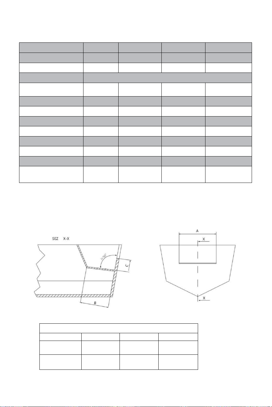
- 5 -
Techniczny informacja:
TYP
YSH-90HP
YSH-150HP
YSH-200HP
YSH-300HP-B
LAKIERKI
NR90
NR150
NR200
NR300
POJEMNOŚĆ CM³
16
18
27
27
Gwint koła
5/8"-18UNF
MAKSYMALNE
CIŚNIENIE BARY
69
69
69
69
OBROTÓW KOŁA
5
5.5
6
7
CYLINDRY
MR90
MR150
MR200
MR300-B
RURA ID [mm]
25
30
32
35
PRĘT ID [mm]
14
16
16
18
SIŁA WYJŚCIOWA/KGF
232
400
470
470
SKOK [mm]
200
198
200
200
OBJĘTOŚĆ [cm3]
67
101
125
142
APLIKACJA
Do
90 KM
W górę Do 150
KM
W górę Do 200
KM
W górę Do 300
KM
Minimalne wymiary studzienki przeciwbryzgowej:
Przed próbą instalacji, upewnij się, że studzienka przeciwbryzgowa
łódź ma następujące mini mama wymiary.
MINIMALNE WYMIARY WANNY BRYZGOWEJ
Numer silnika s
A
B
C
1
560 mm-21,25
cala
152 mm-5,98
cala
152 mm-5,98
cala
2
1110 mm-21,55
cala
152 mm-5,99
cala
152 mm-5,99
cala
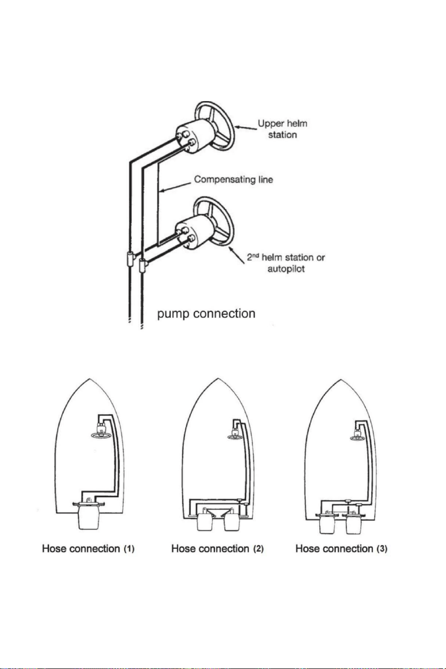
- 6 -
Montaż węży/złączek - podłączenie pompy
Odnieś się do ilustracje poniżej przedstawiają prawidłowe podłączenie węży hełm pompa do
cylindra.
Przyłącze węża
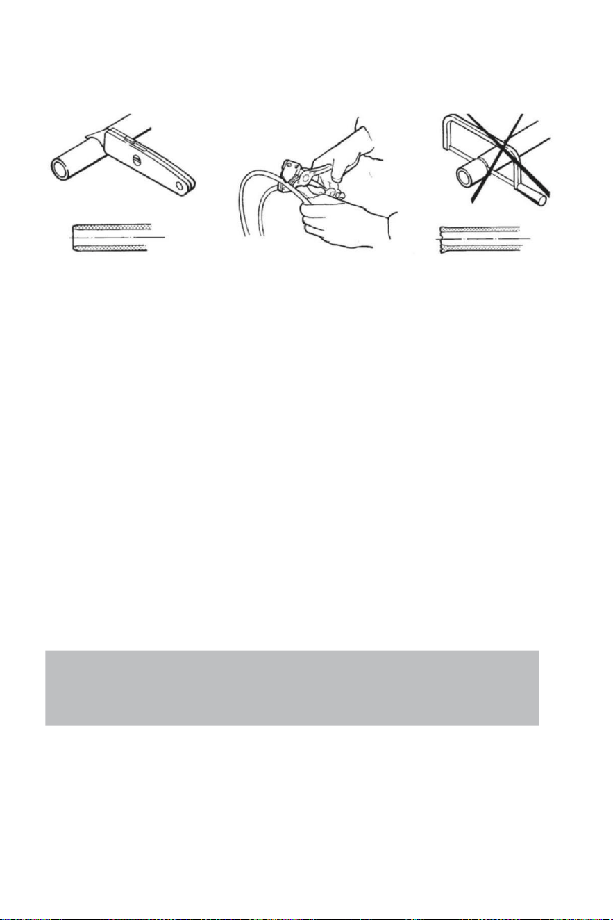
- 7 -
Przyłącze węża
Poleca ten używać z VEVOR sterowniczy węże tylko.
Zawsze próbować Do trasa ten węże przez on najkrótszy ścieżka W zamówienie Do unikać
każdy możliwy strata z moc.W aby zrobić ten powietrze krwawienie z tego system łatwiej jest
zasugerował zamontować węże
poziomo z jakiś skłonność o 3 cm za metr;ten pompa strona ma Do Być wyższy niż ten cylinder
strona.
Zawsze chronić ten węże To Posiadać Do przechodzić Poprzez A różny przedział t Lub
używać odpowiedni złącza grodziowe lub rękawy s .
Wąż gumowy Posiadać Do Być zainstalowany W taki A sposób Oni nie reprezentować jakiś
przeszkoda Do Inny komponenty.
Do nie usunąć ochronny koniec okładki dopóki ten węże Posiadać został kierowany I Czy
gotowy Do Być połączony Do pompa sterowa p, przyłącze węża Lub siłownik(i) sterujący(e).
Dostarczać wystarczający wąż gumowy długości Do umożliwić Do cylinder ruch na wskroś
ten obrócenie łuk I góra/dół ustawienia trymowania/pochylenia z ten silnik(i).
Na wskroś ten wąż gumowy instalacja,zapewnienie ten ochronny czapki pozostać zainstalowany
na ten koniec z ten węże.
Uwaga:
Do nie zainstalować węże W jakiś obszar Gdzie Oni będzie Być narażony Do wysoki ciepło .
Ekstremalne ciepło zmniejsza ciśnienie rozrywające wąż i może spowodować pęknięcie węża
topienie. Zachowaj dużą czystość . Zrób Jasne To kobza i węże Czy doskonale czysty I
bezpłatny z wióry.
Note:
Flexible hoses have to be cut by means of a sharp knife;
never use a saw,as fragments of nylon in the hydraulic system cause serious problems.
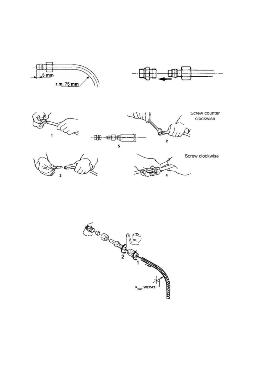
- 8 -
Montaż węża hydraulicznego
Po przecięciu nylonu wąż, pasuje sprzęganie orzech i ten e wsparcie rękaw NA wąż (sprawdź)
To jest właściwie w odniesieniu do koniec z wąż).Po montowanie z orzech , ty Posiadać Do
obcisły przez środki klucz do nakrętek.
Inaczej mówiąc , ty Móc uchwyt elastyczny wąż nylonowy z odłączalnymi końcówkami . Postępuj
zgodnie z instrukcjami ilustracje poniżej pokazywać.
Po ten instalacja czysty ten wewnątrz z ten węże przez dmuchanie Poprzez używając
sprężony powietrze , w celu Do unikać każdy przeszkody I Do usunąć pył I gruz z
przechowywanie.Przed ten odpowietrzanie To Jest Również zasugerowano Do robić A
płukanie z ten system . Zrób nie używać woda .
1 Po przecięciu przykręć złączka rurowa rękaw na rura (leworęczna ) nitka).
2 Nasmaruj złącze rurowe I śruba włóż do rękawa.Zrób Jasne To wewnętrzna osłona z
dawka
rurki
nie należy przestrzegać podczas dokręcania śruba! Upewnij się również To wewnętrzny
poszycie z ten rury Jest nie nękany chwila dokręcanie ten śruba .
3 Sprawdź Tam Jest NIE wewnętrzny ingerencja stawianie A mały śrubokręt do ten rura
sprzęgło przed przystąpienie do montażu węża do steru lub cylinder
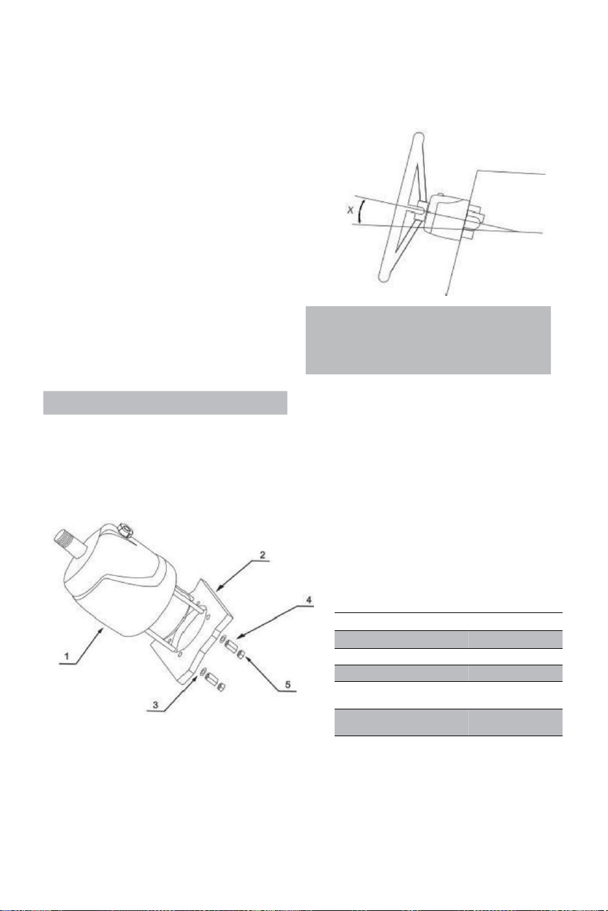
- 9 -
Hydrauliczny układ kierowniczy YSH-150HP
Narzędzia instalacyjne (Aby dokończyć instalacja tego
systemu , Ty potrzebne są następujące narzędzia):
. Otwór piła z 3 . 03 " (77 mm ) średnica
· 0 . 354 " (9 mm ) wiertarka fragment
· 1 . 181 cali (30 mm ) montowanie klucz
· 0 .433 " ( 11 mm ) instalacja klucz
· 0 . 748 " ( 19 mm ) instalacja klucz
· 0 . 669 " ( 17 mm ) instalacja klucz
· 0 .472 " ( 12 mm ) instalacja klucz
· 0 . 945 " (24 mm ) gniazdo klucz
Important:
perform the bleeding procedure manually
and with the helm pump inclined no
more of 10(X).
Steering pump YSH-150HP Installation:
·Określ kąt i ustawić cię instalują się do zapewnić To ten kierownica robi nie ingerować
z innym sprzętem. Sprawdź, czy jest nadal wystarczające przestrzeń za ten most
deska rozdzielcza(2)do montażu i podłączania rur.
RIF.
ILOŚĆ
OPIS
1
1
pompa
2
1
Tablica
3
4
Podkładka
4
4
Nakrętka
przedłużająca
5
4
Zamek
nakrętka
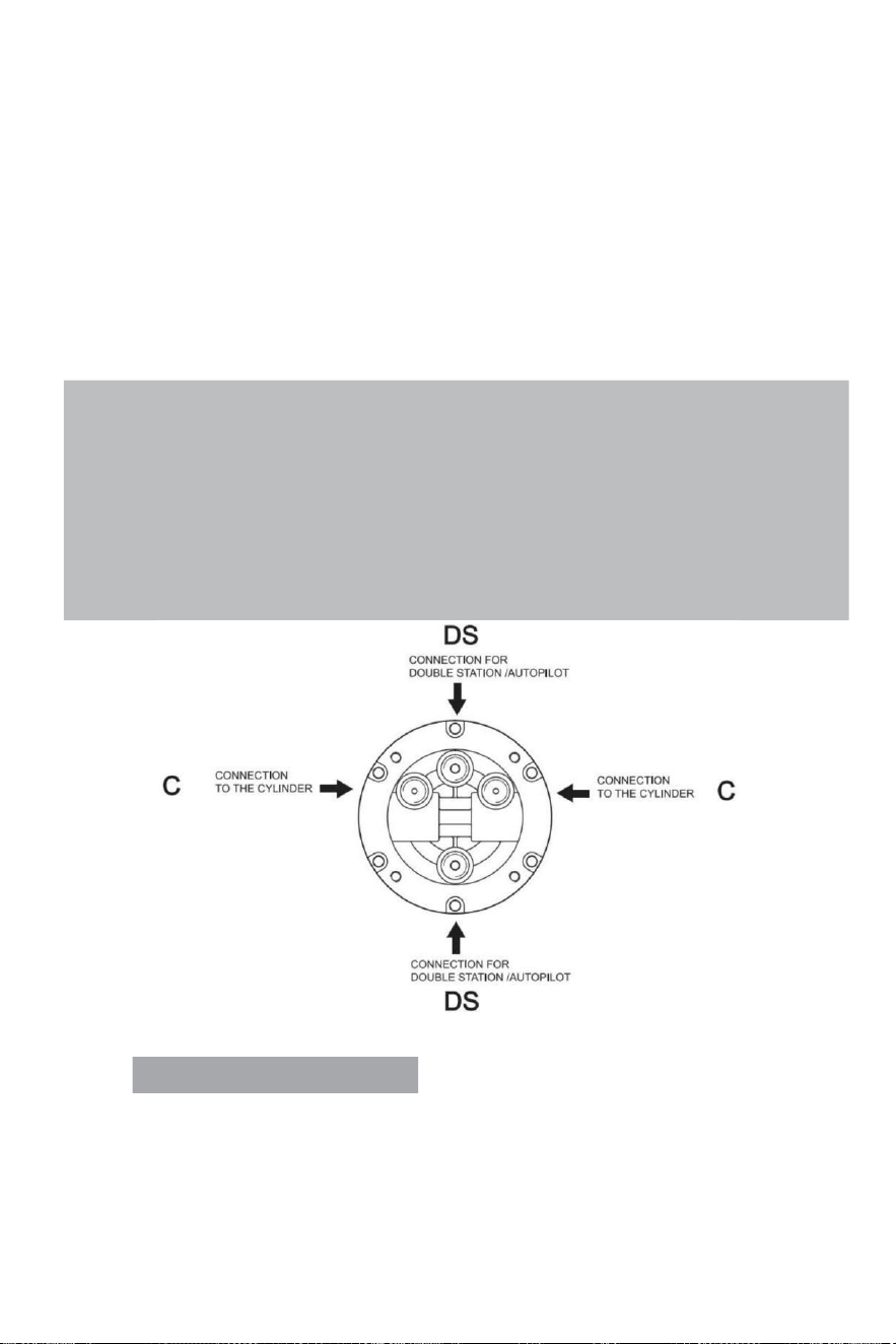
- 10 -
·Przytwierdzać a1:1 dostęp otwór montowanie szablon(w zestawie) z Ten (ma nual)to ten
instrument panel i pozycja montowanie otwór standardowo z wycinak otworów.
· Wiertarka o średnicy 3,03" (77 mm ) otwór I wiertarka cztery 0,354 (9 mm ) średnicy dziury
Jak pokazano NA szablon montażowy.
·Trasa ten zaaranżowany rury Poprzez ten środek 3,03" (77 mm) średnica ter otwór I łączyć To
Do układ kierowniczy pompa (1)
·Zainstalować ten sterowniczy pompa NA ten instrument panel z 4 podkładki (3)i 4 ulga deszczowa
orzechy(4),4 nakrętki zabezpieczające (5), dokręcanie moment obrotowy ≤15N.
·Smarować ten stożek sekcja z wał.Zamontuj ten półkolisty klucz.Miejsce ten sterowniczy koło W
ten wałek kierunkowy i kierownica z piętą klawisz droga dalej ten półkolisty klucz.Miejsce ten
podkładka I dokręcić sterowniczy zamek orzech . Ten dokręcanie moment obrotowy Jest ≤20
Newton .
Note:
·The steering pump should be mounted at a tilt angle of X≤20°.If it is exceeded,it
may cause air to enter the duct and affect the steering function.
·Only use self-locking fasteners provided by VEVOR or standard fasteners.Using non-self-
locking fasteners instead may cause the equipment to loosen or separate.
·Do not open the pump cover or filler cap when installing the steering pump to prevent dirt
and chips from entering the pump and causing the steering function.
·Teflon-like ribbon seals can not be used on pipe nipples,which may cause tape chips to enter
the pump body and thus affect the steering function.(The VEVOR series is a pipe thread
sealing technology that does not require the use of other sealing tape seals.)
VALVE PORTS CONNECTION:
Port oznaczony literą „C”: połączenia z cylindrem/cylindrami
Port oz naczone „DS ”: połączenia do stacji dodatkowej lub autopilota
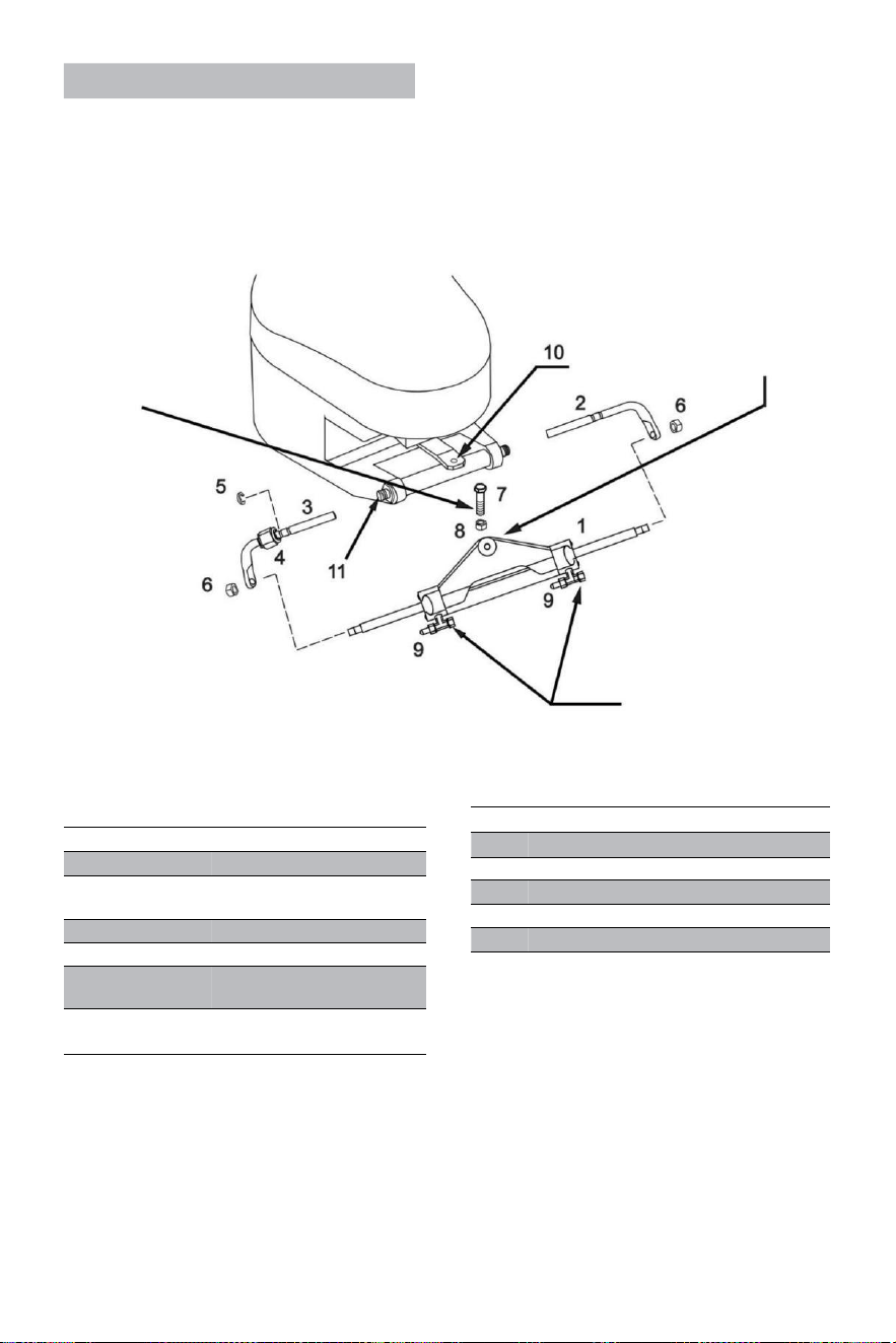
- 11 -
Cylinder YSH-150HP Installation:
OSTRZEŻENIE:
To Jest ważny Do sprawdzać
okresowo , w najmniej każdy
3 miesięcy (lub co miesiąc
Do zastosowań
profesjonalnych),
Prawidłowy moment
obrotowy tej śruby I z
zamek nakrętka.
Ramię cylindra powinno
być przywiązanym do ten
silnik rumpel ramię na
większości marki
z silniki zaburtowe w tym
przypadku To ten rumpel
zakłóca z inne części silnik
zaburtowy, Następnie to
może Być zmontowany pod
glebogryzarką Zamiast.
OSTRZEŻENIE:
Zdejmij czerwone nasadki w
kolejności Do zainstalować
ten wąż osprzęt .
RIF .
ILOŚĆ
OPIS
1
1
Cylinder
2
1
Prawe wsparcie
wsporniki
3
1
Lewe wsparcie wsporniki
4
1
Złączony nakrętka
5
1
Nierdzewny klamra stalowa
(C)
6
2
Tłoczysko zamykający
nakrętka
·Zanim męczący Do zainstaluj, proszę sprawdź czy twój silnik jest odpowiedni dla tego
typu cylindra i zapewnić To twój rufowy tablica przestrzeń Jest z wystarczający
rozmiar Do instalacja .
· Zanim instalacja , proszę smarować ten ruchomy połączenie strony z ten silnik I
cylinder
I ten tłok pręt z wykwalifikowanym personelem morskim środek smarujący i wyprostować twój
silnik Do środek pozycja;
RIF.
QUANTITY
DESCRIPTION
7
1
3/8 connecting bolt
8
1
3/8 Lock nut
9
2
Deflation device
10
1
Engine connecting block
11
1
Engine mounting hole
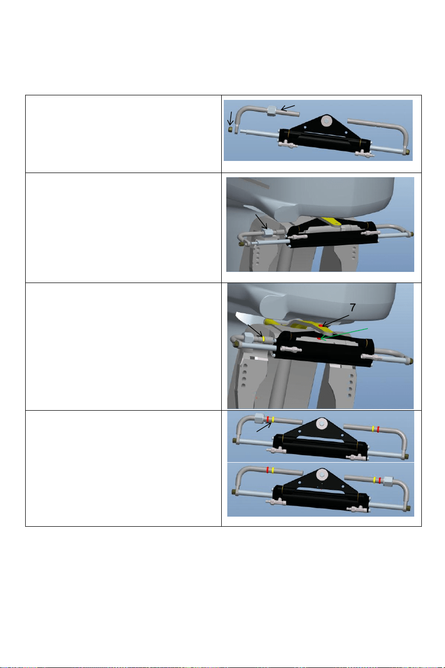
- 12 -
·
Rozluźnij samoblokujący nakrętka (6) na jednym
końcu z cylinder tłok pręt i usunąć ten instalacja
pręt (3).Po usuwanie ten części, zainstaluj
instalacja pręt (3)do ten silnik instalacja
dziura(jak pokazano na rysunku powyżej);
Wyjąć śrubę (7) ze środka otwór z cylindryczny
trójkąt nawias wspornik, regulacja Kąt silnika i
zamocuj cylinder trójkąt nawias Do ten silnik
z śruba(7)i orzech(8)
odpowiedni Do dziura na Płyta przyłączeniowa
silnika. Zwróć uwagę na wahadło lewe i prawe z
ten maszyna Do zapewnić To ten cylinder
będzie nie ingerować z ten ruch z ten silnik
Po instalacja.
Regulować ten silnik Kąt I cylinder tłok pręt
rozszerzenie długość.Zgodnie Do ten luka
między silnik i cylinder prawidłowo zainstalować
nierdzewny stal Zacisk C(5) do ten
odpowiedni rowek montażu pręt.(Zobacz
postać powyżej)
6
3
4
5
7
8
5
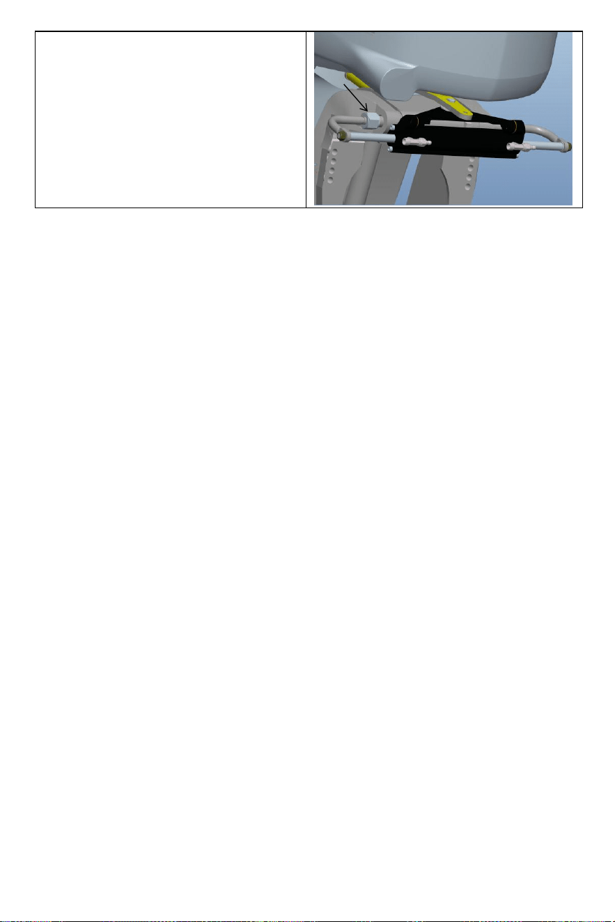
- 13 -
Po zamontowaniu należy dokręcić nakrętkę
zabezpieczającą (4). zaciśnięty Do eli minate ten
operacyjny luz cylindra. Dzięki temu Twoje
doznania będą jeszcze lepsze.
4

- 14 -
· Po ten instalacja Jest kompletny , pchnij twój silnik Do ten lewy I Prawidłowy Do robić A test
uruchomić cylindra . Sprawdź, czy występują jakieś elementy zakłócające podczas pracy cylindra.
tam i z powrotem . Jeśli Tam Jest zakłócenia , ty potrzebować Do ponownie ustawić ten
instalacja . Jeśli Tam Jest NIE
zakłócanie , pchanie ten silnik Do ten koniec z ten lewo / prawo limit . Ten Następny krok
Jest Do zatankować i spaliny;
· Łączyć ten zaaranżowany olej kobza Do ten olej rura stawy (2) w sekwencja , blokada ten
krwawić
połączenia(3)cylindra przygotować Do następny tankowanie I wyczerpujący g kroki do
instalacji ten system.
Warning:
When installing,to avoid bumping the piston rod,it is forbidden to hit the piston rod with wrench or
anything hard.If the piston rod is bruised,it will cause hydraulic oil leakage of the oil cylinder,
which will compromise your product experience.
VEVOR kierunek hydrauliczny ten systemwydech spalin:
Ten procedura pracy wymaga dwóch ludzi do obsługi, osoba móc nie Być zdolny do całkowicie
usunąć Wszystko ten powietrze wewnątrz ten hydrauliczny system Który wyniki W To ten
hydrauliczny wyjście systemowe ciśnienie Jest nie wystarczy, wpływ słabości , powolna reakcja,
zatem
mające wpływ na Twoje doświadczenie z produktem.
Proszę użyć specjalnego ekologiczny olej hydrauliczny dostarczany przez VEVOR Lub Inny
wykwalifikowany specjalista
hydrauliczny olej do tankowania. Nie używać olej hamulcowy.Używanie inne niedopuszczalne
substancje żrące olej może przyczyna nieodwracalne szkody dla ciebie system I wynik w
produkt istnienie niezdolny Do Być
gwarantowany.

- 15 -
Precautions:
·If you fill the pump with hydraulic fluid before connecting the filler tube to the pump,the
filling procedure can be made more quickly and easily.
·In case of emergency,any non-toxic,non-corrosive,non-flammable oil can be temporarily
supplied to the system,but the entire system must be thoroughly cleaned afterwards;
·Please keep refueling tube visible during the entire refueling process.Do not allow oil to
enter the pump. Otherwise,air may be introduced to increase refueling time.
·During the process of refueling and exhausting,the hydraulic oil collected from the air
bleeder manifold of the cylinder can be used directly after a few moments.
·Please protect the environment and properly dispose of used oil.The special hydraulic
oil provided by VEVOR system can be reused after being filtered by the filter with the hole
diameter less than or equal to 38um.
Sprawy wymagają uwagi
Notatka 1 Użyj określonego Lepkość 20 #-32# z hydrauliczny olej, Do nie używać różny typy z
hydrauliczny olej o różnej lepkości, d o nie mieszanka hydrauliczna olej z każdy nieznany płyn.
Uwaga 2 Do nie używać zanieczyszczony olej hydrauliczny, zanieczyszczony olej hydrauliczny
będzie przyczyna hydrauliczny pompa awaria I hałas.
Uwaga 3 Dodaj olej hydrauliczny do hydrauliczny pompa przy ten określone wypełnienie port Do
unikać mieszanie woda Lub zanieczyszczenia. olej hydrauliczny musieć Być utrzymany w pełnym
stanie olejowym w hydrauliczny pompa.
Uwaga 4 Podczas dodawania olej hydrauliczny , powinno być filtrowanym za pomocą A filtr ekran.
NIE Cienki zanieczyszczenia z więcej do oleju może przedostać się więcej niż 5μm-10μm pompa,
która będzie przyczyna strony zablokowanie, hałas, kierunek przełączanie zawór ugryźć i zrobić
olej pompa ponieść porażkę.
Uwaga 5 Powinno być Być NIE bąbelki w olej hydrauliczny, który będzie zwiększyć ten hałas z
hydrauliczny pompa i przyczyna (przyczyna (nieznana) awaria. Pęcherzyki powietrza musieć Być
zwolniony. Proszę odnosić się do strony 11 I 12 z
instrukcja
obsługi konkretnego układu
wydechowego metody
Uwaga 6 W proces używać, To Jest niezbędny Do sprawdzać regularnie czy Tam Jest olej
przeciek W ten pompa ciało, olej rura i olej cylinder I radzić sobie z To W czas .
Kierownica Note 7 grać może Być rozwiązany poprzez zastosowanie ciśnienie Do ten sterowniczy
koło. Ten
procedura wygląda następująco: obróć kierownicę zgodnie z ruchem wskazówek zegara do końca
zamek. Kontynuować obrócenie ten sterowniczy koło dopóki nie poczujesz się ważny opór.
Następnie odkręcić korek wlewu paliwa czapka I Kontynuować pożywny ten paliwo Napełnij pompę
olejem. Dokręć korek wlewu paliwa, I ten sterować koło grać będzie Być wyłączony.
Uwaga 8 Podczas uzupełniania oleju pompa z olej, Proszę użyj olej podsadzkarz dysza pod
warunkiem, że przez nas, Który Jest wyposażony w filtr oleju 60-mesh Do filtr na zewnątrz
zanieczyszczenia W ten olej.
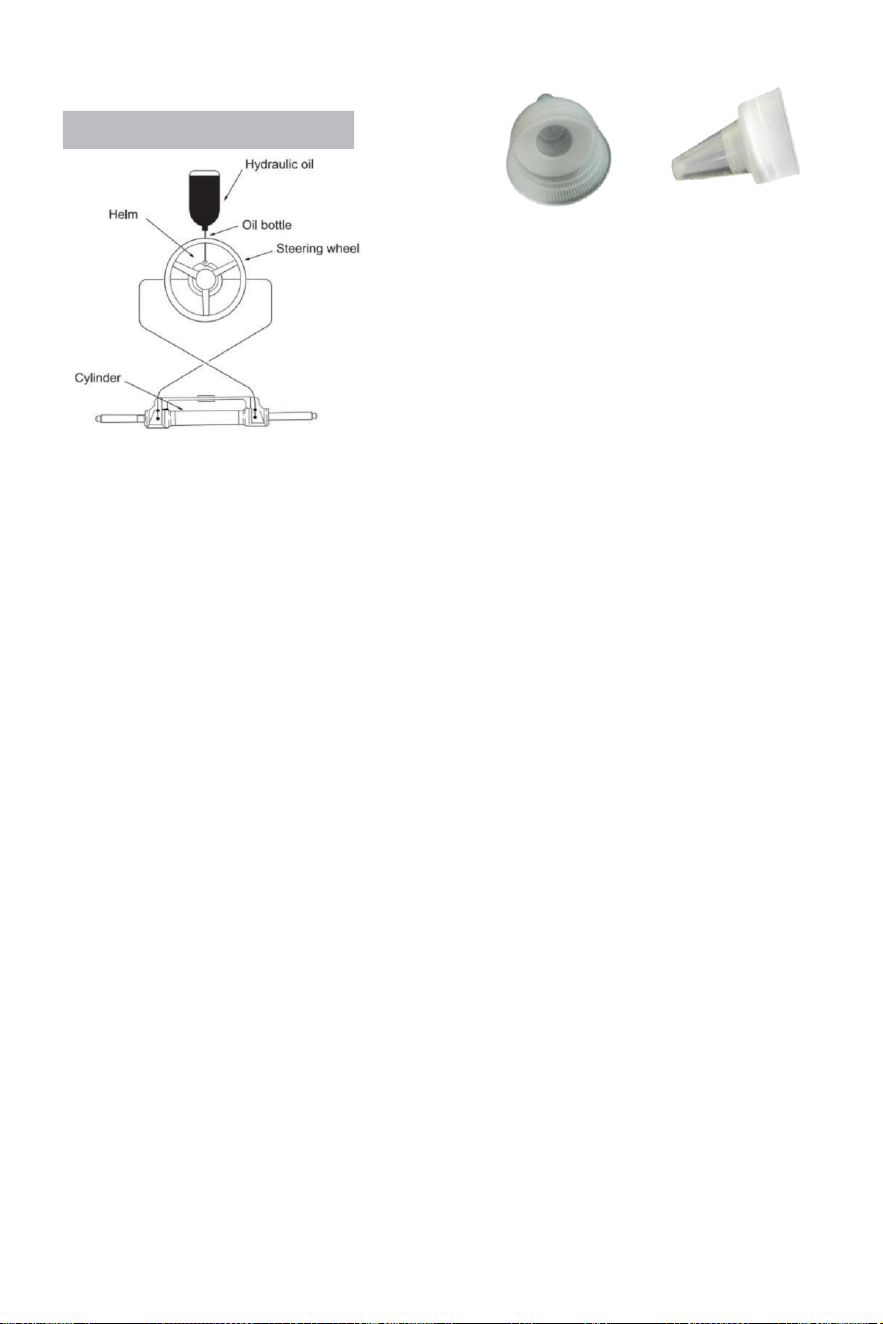
- 16 -
Refueling and Venting Steps:
·Wkręć rurę z gwintem pachwinowym wyposażony w system
do portu pompy paliwa i dokręć, aby upewnić się, że jest szczelny.
·Pasować ostry wierzchowiec w zestawie z tym system
Do ten olej zakrętka butelki.Wkładka ten ostry wlot do
pompy
z pewną siłą wlej olej do wlewu paliwa
dopóki nie będziesz mógł zobaczyć powietrza (tego
butelka Móc być ściśniętym delikatnie Do prędkość w
górę (tankowanie.)
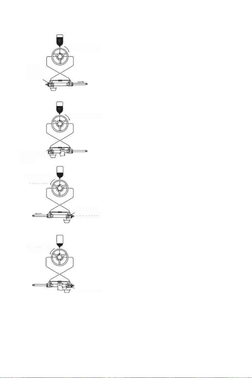
- 17 -
(parameter table)to determine whether the hydraulic
Turn clockwise
Open
left side
bleeder
Turn clockwise
Close left side
bleeder
Turn counter
clockwise
Open right
side bleeder
Turn counter
clockwise
·Zakręt układ kierowniczy kręć powoli
zgodnie z ruchem wskazówek zegara aż
do jednej strony tłok pręt jest w pełni
rozszerzony.Dopasuj rura wydechowa
Do cofnięcie strona z tłok pręt Do zbierać
olej z odpowietrzanie.
·Trzymać ten cylinder Do zapobiegać ten cylinder z
obrócenie, odkręcić ten deflate i na sutku
zagnieżdżonym NA ten
strona z odpowietrznik (nie odkręcać)
To całkowicie, to jest wystarczy jeśli
Ty Móc Widzieć ten olej)obrót ten
sterowniczy koło zgodnie z ruchem
wskazówek zegara, aż Ty Widzieć ten
wewnątrz z tego
wydechowy rura Wydalony
olej Jest stabilny I dokładny , nie bąbelki ,
obrót kierownica przy To samo czas dokręcać
ten
nakrętka deflacyjna ścisłe dopasowanie układu
wydechowego ;
·Kontynuować Do zakręt ten sterowniczy koło
przeciwnie do ruchu wskazówek zegara, aż
oryginalne wycofanie strona z tłoczysko
całkowicie wysunięte, pasuje ten ex aust
rura Do ten wycofać strona z tłok pręt
Do zbierać ten olej z odpowietrzanie
·Trzymaj cylinder zapobiec ten cy linder
od obracania, odkrę ci ć nakrętkę złącza
dekompresyjnego jednego bok.(Nie odkręcić
to jest kompletne , to jest to wystarczająco Jak
długi Jak Ty Móc Widzieć ten
olej).Obróć ten sterowniczy obracaj zgodnie z
ruchem wskazówek zegara, aż Widzieć ten olej
z ten rura spuszczająca powietrze jest stabilna,
nie bąbelki, dokręć hemofilik zamknij, zamknij
deflacja urządzenia.
·Obróć kierownicę zgodnie z ruchem wskazówek
zegara/przeciwnie do ruchu wskazówek zegara
kilka czasy Do sprawdzać liczba z pełne obroty steru
płyn w rurce ma został całkowicie wykluczone.Jeśli
jest Nadal powietrze, liczba z pełny ster ( zwiększy się.)
Jeśli Tam Jest Nadal A działka powietrza, które Jest nie
wykluczone, wtedy powtarzać
procedura (3)~(6). Jeśli Tam Jest A mały kwota z
powietrze , zrobić
pełny ster W jeden bezpośredni, odwrotny mały s emi
koło, zrób pełny
ster ponownie, zrób Ten dla 5-6 czasy Do kierunek lewy
I Prawidłowy kierunek.
Close right side
bleeder

- 18 -
·Po wokół ster test przejść, usunąć ten paliwo
rura I rura odpowietrzająca, śruba paliwo
czapka, zestaw ten spuszczony złącze rękaw,
ten nie używany hydrauliczny olej Jest
Zamknięte Do późniejszy konserwacja i
naprawa. (Sprawdź układ hydrauliczny) pu m
p olej powierzchnia raz na
kwartał,niewystarczający olej będzie
przyczyna
(coś nienormalnego.)

- 19 -
Błędy i rozwiązania:
Ten następny Czy ten bardzo wspólny awarie I ich powoduje I rozwiązania .
Gdy ten ster obraca się z pełny ster (cylinder pełny) udaru mózgu ), tam Może niewielki
opór I wewnętrzny części wydają dźwięk kliknięcia, który pochodzi z zawór wewnętrzny
basen piłka I łożysko stal piłka kiedy oni Czy działanie.
To jest normalna zjawiska. Proszę Do nie myśleć To Jest spowodowany przez usterki.
WADA PRZYCZYNA
ROZWIĄZANIE
Hydraulika ster Jest
całkowicie zablokowany
podczas instalacja.
Rura zablokowanie
między hydrauliczny
pompa I siłownik
hydrauliczny.
Sprawdź czy ten wąż gumowy rura Jest
zatkany Lub zgięty, jeśli to Jest zgięty,
musisz zastępować uszkodzony
wąż lub może wynik w utrata
sterowniczy I poważny obrażenia ciała
lub nieruchomość szkoda.
To jest trudne Do
zatankować ten system, nawet
Kiedy ten
system mówi ten paliwo Jest
pełne bąbelki Kontynuować Do
muzyka pop na zewnątrz z ten
olej pompa.
·Tam Jest powietrze W ten system
·Krwawić dopasowywanie przecieki
·Hydrau l ic pipping ma
meandrowy Lub pochylenie się
uraz s.
Zainstalujsystem odpowiednio według do
instrukcja instalacji. wlot rura musieć
Być zawsze w górę.
·Dokręcać ten deflacja armatura.
·Rozwijać I Stra i Lighten ten wąż
gumowy Lub zastępować ten
uszkodzony wąż gumowy.
Gdy używając ten system
Do steruj, potrzebujesz Do
obracać pełny ster szybko Do
wiele czasy.
·Hydrauliczny pipping ma
zgięty urazy
·Tam Jest gaz Lub Cienki bąbelki
W ten hydrauliczny olej.
·Nieprawidłowy układ hydrauliczny
olej był nami
·Rozwijać I wyprostować ten
wąż lub zastępować ten uszkodzony
wąż gumowy.
·Zatankować Lub wydechowy
odpowiednio
zgodnie z instrukcja instalacji.
·Używać ten prawidłowy układ
hydrauliczny o i l
Gdy ten system Jest
pełny ster, ten sterowniczy
koło Tylko nie praca.
Tam są brud
zanieczyszczenia W ten
hydrauliczny pompa
zawór
·Nie używać ten uszczelnienie
„pasmowe” taśma Na ten interfejs.
·Brać oprócz ten hydrauliczny pompa
Do czysty ten brud.
Ten system może sterować
ten statek łatwo kiedy ten
statek Jest
stacjonarny,Jednakże, To jest
bardzo trudny Do sterować
chwila żeglarstwo.
·Mała kierownica był
wybrany.
·Silnik połączenie Jest
nie ustawić
prawidłowo,
Poduszka powietrzna Jest
wygenerowano W
ten system I powietrze nie
jest wyłączony całkowicie.
·System konfiguracje
przekroczyć moc
ograniczenia.
·Zmień na A większy kierowanie koło
z Który ten maksymalny średnica
Jest bez nadzwyczajny 56 cm.
·Regulować ten silnik
połączenie ustawienia
prawidłowo.
·Sprawdź olej powierzchnia
hydraulicznych pompę, zresetuj
tankowanie i wentylacja prawidłowo.
Kierownica obroty Do
lewy port strona,
Statek skręca w prawo
Zły olej rura połączenie
Zamień tedwa olej kobza z ten cylinder z
nawzajem I zainstalować ich .
Puszka cylindryczna nie Być
zainstalowany Do ten silnik.
Każdy cylinder wymaga
odpowiedni silnik model.
Proszę zapoznać się z ten
podręcznik Lub on obsługa klienta
z ten kupiec Do zmiana ten model.
Gdy ten ster pompa sięga ten zatrzymywać się punkt(cylinder) pełny udaru mózgu), mały kwota z układ
hydrauliczny dryf Jest normalna I ten ster pompa Jest nie 100% zablokowane.

- 20 -
Konserwacja
Ostrzeżenie:
Następny ten rutyna konserwacja harmonogramy Jak zarysowany poniżej, w ten przedział
czasowy odnotowano wolę zapewnić lata użytkowania Twojego układu kierowniczego VEVOR, a
także trzymać Ty I twój pasażerowie bezpieczna z ten
zagrożenia, które są obecne NA I z wody.
Awaria Do zastosować się z konserwacja sprawdza móc wynik N strata z kierowanie,
powodujące nieruchomość uszkodzenia i/lub osobisty obrażenia.
Kontrole są konieczne co roku i musieć Być Carrie D na zewnątrz przez specjalistyczny morski
mechanika. Sprawdzać ten wał I ten o pierścienie z cylinder, ten o pierścienie z hełm pompa, ta
dopasowania z
cylinder I pompa sterowa W aby zamówić zapobiegać przecieki.
Sprawdzać szczelność z Wszystko elementy złączne/ elementy mocujące na wskroś ten
kierownica system.
Wyczyść system używając świeżej wody I nieścierny płyn.
Czyszczenie płyny zawierający amoniak, kwasy Lub każdy Inny żrący składniki musieć nie
Być używany Do czyszczenie dowolnego strony z hydrauli c sterowniczy system.
DO nie używać hamulec obrazy olejne Lub automatyczny przenoszenie płyn (ATE).Użyj tylko
kompatybilny hydrauliczny obrazy olejne.
Wcześniejszy Do każdy używać:
· Sprawdzać Płyn poziom W najwyższy hełm pompa
·Zweryfikuj natychmiast reakcja układu kierowniczego Kiedy obrócenie sterowniczy
koło(a) (Zapewnij silnik obroty Kiedy kierowanie koło jest obrócony).
· Wizualnie sprawdzać Wszystko sterowniczy węże I pasujące elementy Do zużycie , zagięcia
i / lub przecieki .
·Sprawdź, czy nie ma wiązań, luzu, zużycia Lub nieszczelny układ kierowniczy komponenty.
Ostrzeżenie:
DO NIE działać łódź jeśli w ogóle część Jest nie W prawidłowa praca stan : schorzenie .
W Ten proszę o pomoc Brać zdjęcia natychmiast I kontakt twój kupiec.
Po Pierwszy 20 godzin , potem co 100 godzin Lub 6 miesięcy następnie ( co kiedykolwiek komes
Pierwszy ):
· Wszystko zwrotnica znakomity powyżej
·Sprawdzać szczelność z WSZYSTKO elementy złączne na wskroś ten sterować
system.Dokręć Do prawidłowy wymagane są specyfikacje momentu obrotowego .
·Sprawdzać Do gra mechaniczna Lub pomyje na wskroś sterowniczy system ,poprawny w razie
potrzeby.
·Sprawdzać Do znaki z korozja.Jeśli korozja jest obecna kontakt twój kupiec.
Po każdy 200 godzin lub 12 miesięcy ( co kiedykolwiek komes Pierwszy ):
· Wszystko zwrotnica znakomity powyżej .
·Usunąć wsparcie pręt z silnik sterowanie/pochylenie rurka.Czysta silnik sterowanie /pochylenie
rura I ponownie nasmarować używając Dobry jakość morska smar.
·Smaruj pręt podtrzymujący hojnie.
·Smar Wszystko kontakt zwrotnica pokazano W ten cylinder I krawat bar instalacje.
DO NIE zdejmij glebogryzarkę przykręcić do ponownie nasmarować.
·Usunąć kierownica I ponownie nasmarować koło wał używając A Dobry jakość morska smar.
·Sprawdź czystość oleju hydraulicznego, przepłucz jeśli to konieczne.
Jakakolwiek praca istnienie wykonywane za pomocą układu kierowniczego MUSIEĆ Być
zakończony przez wykwalifikowany mechanik z pracą wiedza z system.
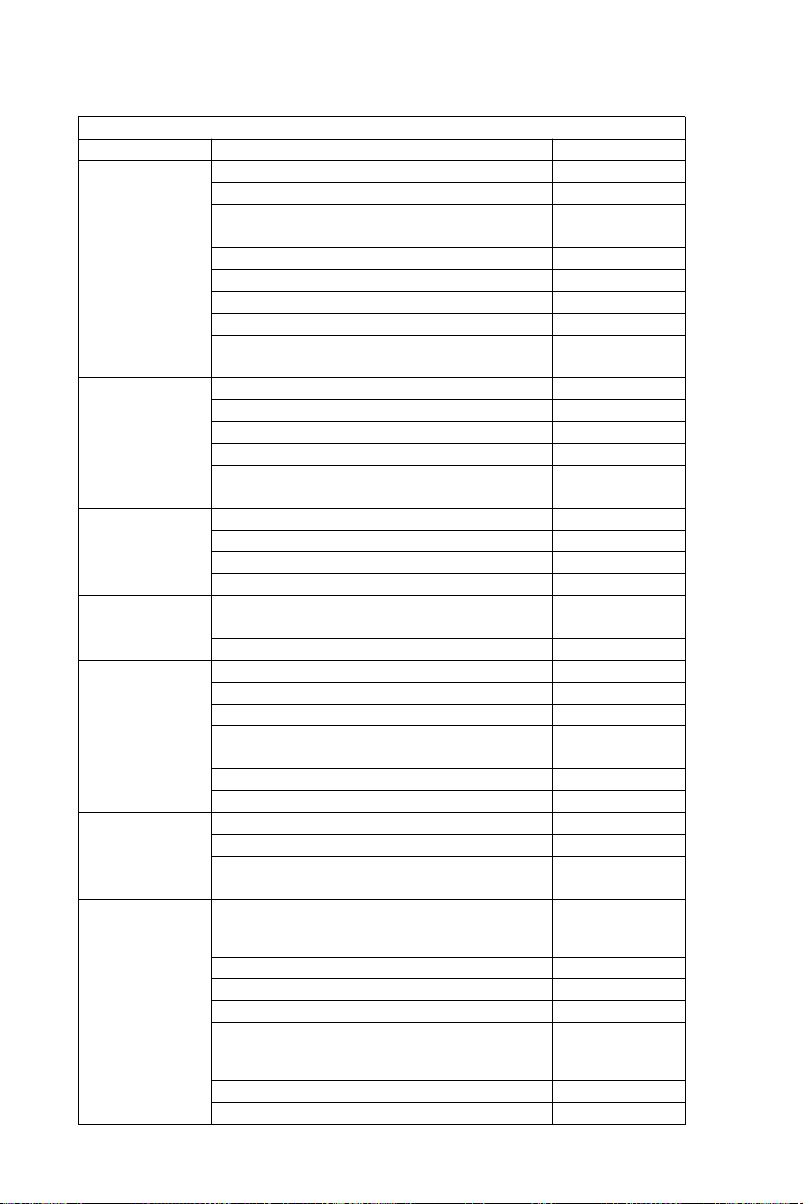
- 21 -
Mecz lista
HYDRAULICZNY UKŁAD KIEROWNICZY DO 150 KM
SILNIK
MOC
ROK
Yamaha
60-702 Udar
1990-2008
75C-902 Udar
1998-2008
F70 4-suwowy
2010-dzisiaj
115C-130B 2 Udar
1990-2008
150F
1996-2007
150 HPDI VMAX 2-suwowy
2000-2008
F75-F80 EFI 4Stroke
1999-2007
F100-F115-F150 EFI 4-suwowy
1999-2007
F80-F100 4-suwowy
2000-dzisiaj
F115-F150
2004-dzisiaj
Honda
BF80-BF90 4-suwowy
1995-dzisiaj
BF115D
1998-2009
BF115A
2009-dzisiaj
BF130A
1998-2005
BF135-BF1504 Skok
2005-dzisiaj
BF90-BF150V-TEC 4-suwowy
2008-dzisiaj
Suzuki
DF70-80-904 Skok
1998-dzisiaj
DF100-115-1404 Skok"
1998-2008
DF100-115-1404 Skok nowy model
2008-dzisiaj
DF 1504 Udar
2006-dzisiaj
Tohatsu
Nissan
70-902 Udar mózgu
2004-dzisiaj
115-120-1402 Udar mózgu
2004-dzisiaj
90-90-115TLD 4-suwowy
2004-2011
Rtęć
Marynarz
75-90 2 Udar
1990-2008
115-125-150 EFI 2-suwowy
1990-2007
90-115-125 Optimax 2 Udar
2004-dzisiaj
135-150 Optimax 2 Udar
1999-dzisiaj
80-90 EFI 4-suwowy
2000-dzisiaj
100-115 EFI 4-suwowy
2007-dzisiaj
150 Czterosuwowy 4-suwowy
2011-dzisiaj
Evinrude
E50-E55-E602 Skok
2004-dzisiaj
E75-E902 Udar mózgu
2004-dzisiaj
E115-E130-E1352 Skok V4
1995-dzisiaj
1995-dzisiaj
E1502 Skok V6
Selva
50-Madeira/Rekin tępogłowy-60
Rekin szary/ St.tropez-70 Mako
Shark 2 Stroke
1996-2008
80 Portofino Tigershark 2 Udar
1995-2008
150 Biały rekin 2 Udar
2001-2007
50-60 Dorado EFI 4-suwowy
2001-2007
100 EFI Marlin -115 EFI Narwhal-
150 EFI Orka 4-suwowa
2000-dzisiaj
Johnson
BJ60-704 Skok
2001-2007
BJ90-115-140 4-suwowy
2001-2007
J90-115V4 2-suwowy
1995-2007
- 22 -
Ostrzeżenie – Aby zmniejszyć ryzyko obrażeń, użytkownik
musieć Czytać instrukcje instrukcję obsługi uważnie.
Producent: Shanghaimuxinmuyeyouxiangongsi
Adres: Shuangchenglu 803nong11hao1602A-1609shi,
baoshanqu, szanghaj 200000 CN.
Importowane do Australii: SIHAO PTY LTD. 1 ROKEVA
STREETEASTWOODNSW 2122 Australia
Importowane do USA: Sanven Technology Ltd. Suite 250,
9166 AnaheimPlace, Rancho Cucamonga, CA 91730
REP
UK
YH CONSULTING LIMITED. C/O YH Consulting
Limited Office 147, Centurion House, London
Road, Staines-upon-Thames, Surrey, TW18 4AX
REP
EC
E-CrossStu GmbH
Mainzer Landstr.69,
60329 Frankfurt am Main.

- 23 -
Hydraulische besturing Voor
boten
Model : YSH -150 pk
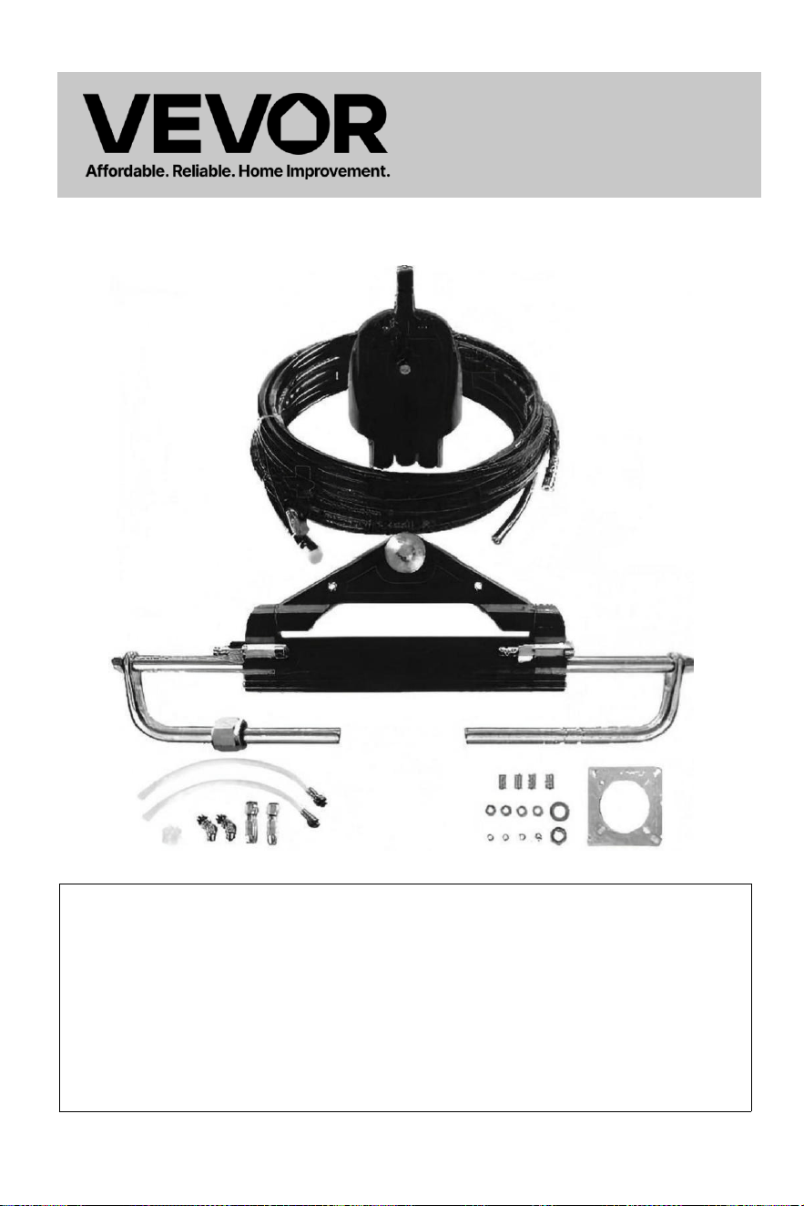
- 1 -
Hydraulische
besturing
Voor
Boten
Model : YSH -150 pk
Dit is het origineel instructie, lees alles alstublieft handmatig
instructies
zorgvuldig door voordat u gaat werken. VEVOR behoudt zich een
duidelijke interpretatie van onze gebruikershandleiding. Het uiterlijk
van het product zal zijn onderwerp naar het product dat u ontvangen
. Neem ons niet kwalijk dat we u niet meer op de hoogte stellen als
er problemen zijn met de technologie of software. updates over onze
product.
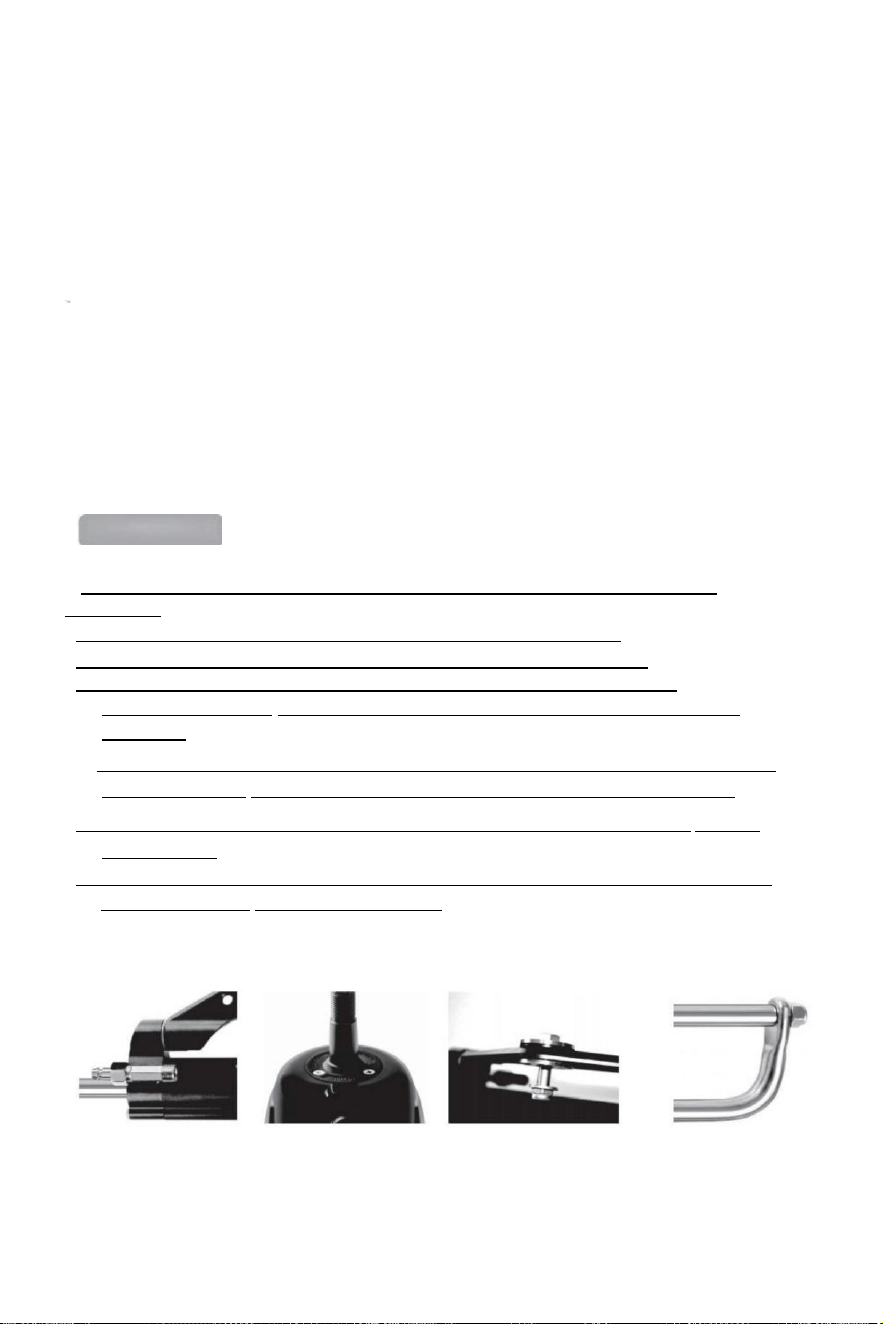
- 2 -
Hartelijk dank voor uw aankoop van het VEVOR hydraulische stuursysteem.
In deze handleiding worden de verschillende functies van dit systeem uitgebreid beschreven,
zodat u: kan Ervaar ten volle hoeveel optimaal plezier dit product u kan bieden.
VEVOR hydraulisch sturen systeem is gebaseerd op het concept van moderne industriële
ontwerp,de hoog efficiëntie, hoog overdragen stroom zuiger pomp technologie is
toegepast naar de ontwerp en de vervaardiging van stuurinrichting van een schip, die
uw sturen systeem stabieler, slimmer en meer betrouwbaar.
De belangrijkste componenten van de sturen versnelling Zijn hoog kracht
aluminium legering En roestvrij staal dat gebruikt kan worden in wreed maritieme
omstandigheden En verleng de
levensduur van stuurinrichting .
De sturen versnelling zullen verlichten Jij van de zwaar En onbuigzaam
mechanisch schacht sturen, wat uw pijnlijke armen kan redden. Het kan het plezier van
het rijden vergroten speedboot.
Main features:
● De besturing pomp is met compacte binnenstructuur en de modieuze En mooi
verschijning .
●Ingebouwde tweewegvergrendelingsklep elimineert het reboundkoppel.
● Gemakkelijk te vervangen de schacht t zegel,gebruiksvriendelijk ontwerp ;
●Stuuras met speciaal oppervlak behandeling niet alleen heeft kracht En
betrouwbaarheid,maar Ook heeft de kenmerken van slijtage weerstand, corrosie
weerstand.
● Hoge sterkte aluminium legering schelp En oppervlak behandeling proces kan ervoor
zorgen zijn slijtage en corrosiebestendigheid en watererosie voorkomen effectief.
● Bies: Hoogwaardig nylon snelkoppelingen 1/4-pijp maakt de installatie compact En Het
is herbruikbaar .
●De gebruik van aangepast hoog -standaard hydraulisch o il kan verbeteren de smering
van onderdelen En afdichtingsbescherming.

- 3 -
Algemene veiligheidsregels en garantie
Deze installatie- en onderhoudshandleiding is een integraal onderdeel een deel van
het product en moet zijn volledig begrepen worden door de gebruiker vóór de installatie .
De installatie, het onderhoud en de overdracht van hydraulisch richting systeem
componenten van VEVOR serie van producten moeten zijn klaar door de
geautoriseerd En gekwalificeerd professioneel
technici.VEVOR serie van producten implementeert de garantie voor twee jaren
aftersales service, wanneer met behulp van de product,Als er een is Heeft u een vraag
of probleem, neem dan contact op met de dealer op tijd.VEVOR zal de juiste begeleiding
bieden . VEVOR zal geen verantwoordelijk voor de gevolgen van ongeoorloofde
demontage of ontmanteling.
Zonder afbreuk te doen aan de aard van het product, heeft VEVOR het recht rechten
naar maken veranderingen naar de beschrijving informatie En illustraties bevatte in
dit handleiding,VEVOR aanvaardt geen enkele verantwoordelijkheid voor de nadelige
gevolgen die worden veroorzaakt door het omgaan met deze handleiding in welke vorm
dan ook andere illegale middelen wat maakt de gebruiker kan niet volgen de
standaard installatie- instructies.
Installatie Voorzorgsmaatregelen:
● Gebruik componenten mits door Alleen VEVOR,De onderdelen geleverd
door de ander fabrikanten kunnen oorzaak veiligheidsrisico's En
beïnvloeden de sturen functie;
●Aan alle pijpen verbinding alleen draden zeehonden zo een als Loctite PST of
equivalent
kit moet worden gebruikt. Niet gebruiken (banding) of soortgelijke afdichtingstapes, omdat
dit kan leiden tot brokstukken binnenkomen het lichaam van de pomp En oorzaak de
blokkade van de pijp.
●Gebruik 10# of 15# speciaal hydraulische olie die gekwalificeerd is en milieuvriendelijk is
vriendelijk. Gebruik in plaats daarvan andere olie (zoals remolie) kan onherstelbare schade
veroorzaken naar uw uitrusting, waardoor u de besturing verliest functie en geen garantie.
●De minimale buigradius van de De pijp is 1"18(30CM). Raak de scherp
voorwerpen. Voortdurend buigen, wrijven, krassen of verdraaien kan veroorzaken de pijp die
moet worden
beschadigd en breuk als gevolg van naar de normale stuurdruk , waardoor er verlies van
sturen functie.
●Laat de pijp niet vallen vrij bij gebruik, gebruik alstublieft draad of ander PVC-materiaal om
repareren,zodat naar mogelijke veiligheidsrisico's vermijden.
● Regelmatig onderhoud van systeemcomponenten en inspectie van leidingen En
uitrusting voor dragen of schade kan verlengen de gebruiksduur van jouw apparatuur.

- 4 -
Paklijst:
SKU
Model
Verpakkingsaccessoires
Hoog-
druk
olie pijp
lengte
YYZXDB150HP0
5UTKJ001V0
YSH-
150 pk
Hydraulische pomp*1
Montageplaat*1
Gebruiksaanwijzing*
1 Olieman pot*1
Olievulbuizen*2
135-graden elleboogconnector
*2 Montagebussen *4
1/4 wasmachine*4
1/4-20UNC noten*4
5/8-18UNF borgmoeren*2
5/8
wasmachine*2
0
YYZXXTTJ90HPI
VK97001V0
YSH-
90 pk
Hydraulische pomp *1
Hydraulische stuurcilinder *1
Montageplaat *1
135-graden
elleboogconnectoren *2 Snelle
connectoren *2
Montagebussen *4
1/4 wasmachine*4
1/4-20UNC noten*4
5/8-18UNF borgmoeren*2
5/8 wasmachine*2
Transparant slang met connector
*2 Kunststofvet tepel *1
Gebruiksaanwijzing *1
Oliekan *1
0
YYZXXTTJ90HP
DLO3P001V0
YSH-
90 pk
Hydraulische pomp*1
Hydraulische stuurcilinder*1
Hogedrukolieleidingen*2
Montageplaat*1
135 graden
ellebogen*2 Snelle
connectoren*2
Montagebussen*4 1/4
wasmachine*4
1/4-20UNC noten*4
5/8-18UNF borgmoeren*2
5/8
wasmachine*
2
Transparant slangen met
aansluitingen*2 Kunststofvet tepel
e*1
Instructies*1
Oliekan*1
20 voet
YYZXXTTJ90HP
WYCCR001V0
YSH-
90 pk
24 voet
YYZXXTTJ150HI
HNTU001V0
YSH-
150 pk
20 voet
YYZXXTTJ150H
3TSCX001V0
YSH-
150 pk
24 voet
YYZXXTTJ150H
3E857001V0
YSH-
150 pk
26 voet
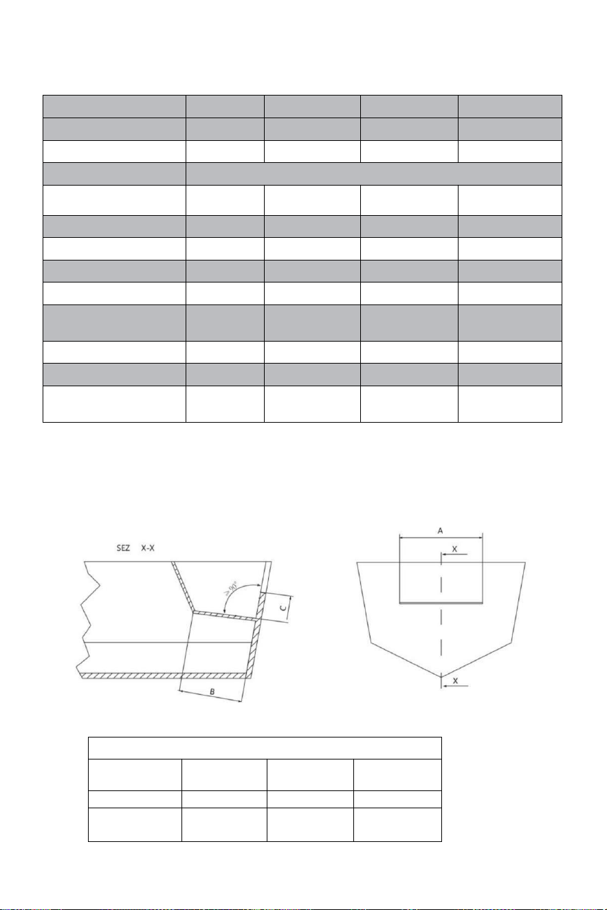
- 5 -
Technisch informatie:
TYPE
YSH-90HP
YSH-150HP
YSH-200HP
YSH-300HP-B
POMPEN
NR90
NR150
NR200
NR300
CAPACITEIT CM³
16
18
27
27
Wieldraad
5/8"-18UNF
MAXIMALE DRUK
STAVEN
69
69
69
69
WIELOMDRAAIEN
5
5.5
6
7
CILINDERS
MR90
MR150
MR200
MR300-B
BUIS ID[mm]
25
30
32
35
HENGEL ID[mm]
14
16
16
18
UITGANGSKRACHT/K
GF
232
400
470
470
SLAG [mm]
200
198
200
200
DEEL [cc]
67
101
125
142
SOLLICITATIE
Tot
90 pk
Omhoog naar
150 pk
Omhoog naar
200 pk
Omhoog naar
300 pk
Minimale afmetingen spatwaterput:
Voordat u het probeert installatie, zorg ervoor dat de spatwaterput van uw
boot heeft het volgende mini -moeder afmetingen.
MINIMALE SPLASHWELL-AFMETINGEN
Nummer van
motors
A
B
C
1
560 mm-21,25"
152 mm-5,98"
152 mm-5,98"
2
1110 mm-
21,55"
152 mm-5,99"
152 mm-5,99"
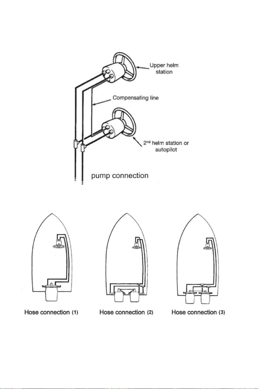
- 6 -
Slangen/fittingen installatie- pompaansluiting
Raadpleeg illustraties hieronder voor de juiste aansluiting van slangen van roer pomp naar cilinder.
Slangaansluiting
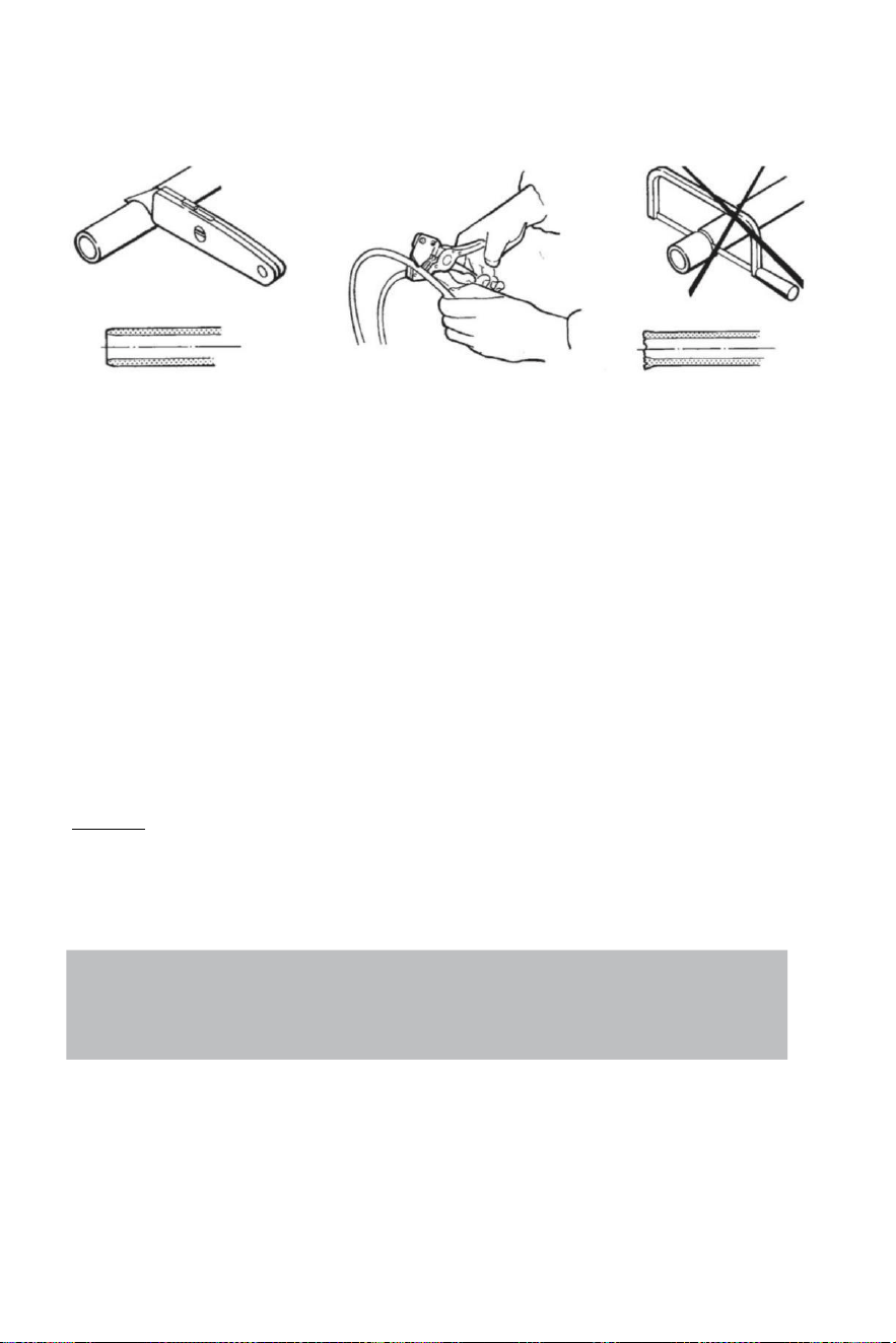
- 7 -
Slangaansluiting
Aanbevolen de gebruik van VEVOR sturen slangen alleen.
Altijd poging naar route de slangen via de kortste pad in volgorde naar voorkomen elk mogelijk
verlies van macht.In bestelling om te maken de lucht bloeden van de systeem gemakkelijker, het is
voorgesteld monteren de slangen
horizontaal met een helling van over 3 cm per meter;de pomp kant heeft naar zijn hoger dan
de cilinder kant.
Altijd beschermen de slangen Dat hebben naar doorgang door A verschillend compartiment t
of gebruik geschikt schotconnectoren of mouwen .
Slang hebben naar zijn geïnstalleerd in zo een A manier zij niet doen vertegenwoordigen een
obstakel voor ander componenten.
Doen niet verwijderen beschermend einde dekt tot de slangen hebben geweest gerouteerd
En Zijn klaar naar zijn aangesloten naar de roerpomp , slangaansluiting of stuurcilinder(s).
Voorzien voldoende slang lengtes naar toestaan voor cilinder beweging door de draaien
boog En omhoog/omlaag trim-/kantelinstellingen van de motor(en).
Door de slang installatie,zorg ervoor de beschermend doppen blijven geïnstalleerd op de einde
van de slangen.
Aandacht:
Doen niet installeren slangen in een gebied waar zij zullen zijn blootgesteld naar hoog hitte .
Extreem warmte vermindert de slangbarstdruk en kan ervoor zorgen dat de slang barst
smelten.Oefen grote netheid.Maak Zeker Dat pijpen en slangen Zijn perfect schoon En vrij van
spanen.
Note:
Flexible hoses have to be cut by means of a sharp knife;
never use a saw,as fragments of nylon in the hydraulic system cause serious problems.
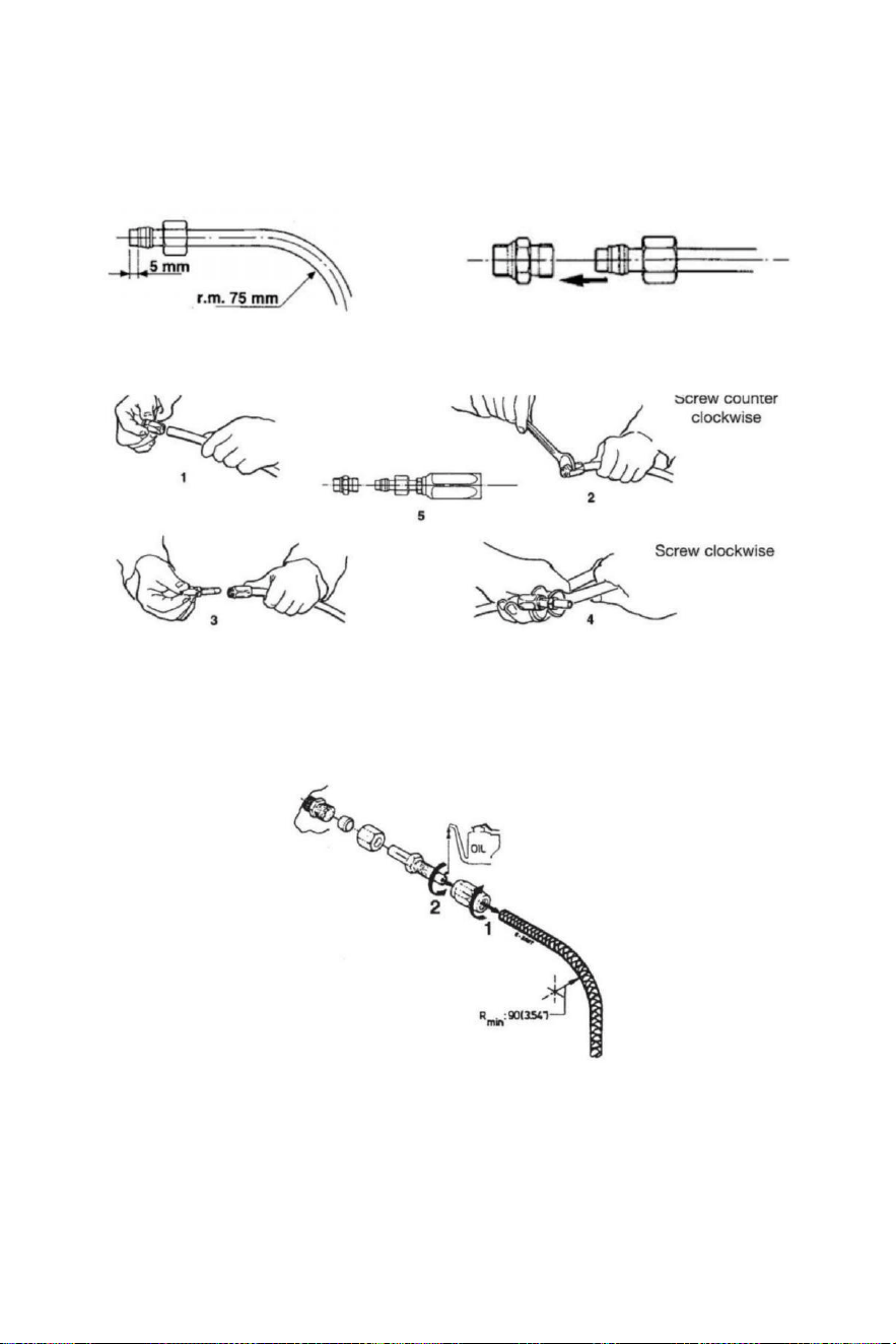
- 8 -
Installatie van hydraulische slangen
Na het knippen van het nylon slang,pas de koppeling moer en de steun mouw op de slang
(controleren) Het is goed in relatie tot de einde van de slang).Na de montage van de noot , jij
hebben naar nauw door middel van een moersleutel.
Anders , jij kan berg nylon flexibele slang met herstelbare fittingen . Doe zoals de illustraties
hieronder show.
Na de installatie schoon de binnen van de slangen door blazen door met behulp van
gecomprimeerd lucht , in volgorde naar voorkomen elk obstakels En naar verwijderen stof En
brokstukken van opslag.Voor de luchtverlies Het is Ook voorgesteld naar maken A spoelen
van de systeem . Doen niet gebruik water .
1 Schroef na het snijden de buiskoppeling mouw op de buis (linkshandig ) draad).
2 Olie de buiskoppeling En schroef het in de mouw.Maak Zeker Dat de interne omhulling van
de
slangdosis
niet volgen tijdens het aandraaien van de schroef! Zorg er ook voor Dat de interne
omhulsel van de buizen is niet uitgeknepen terwijl aanscherping de schroef .
3 Controleer daar is Nee intern interferentie zetten A klein schroevendraaier naar binnen de
buis koppeling voor doorgaan met de installatie van de slang aan het roer of cilinder
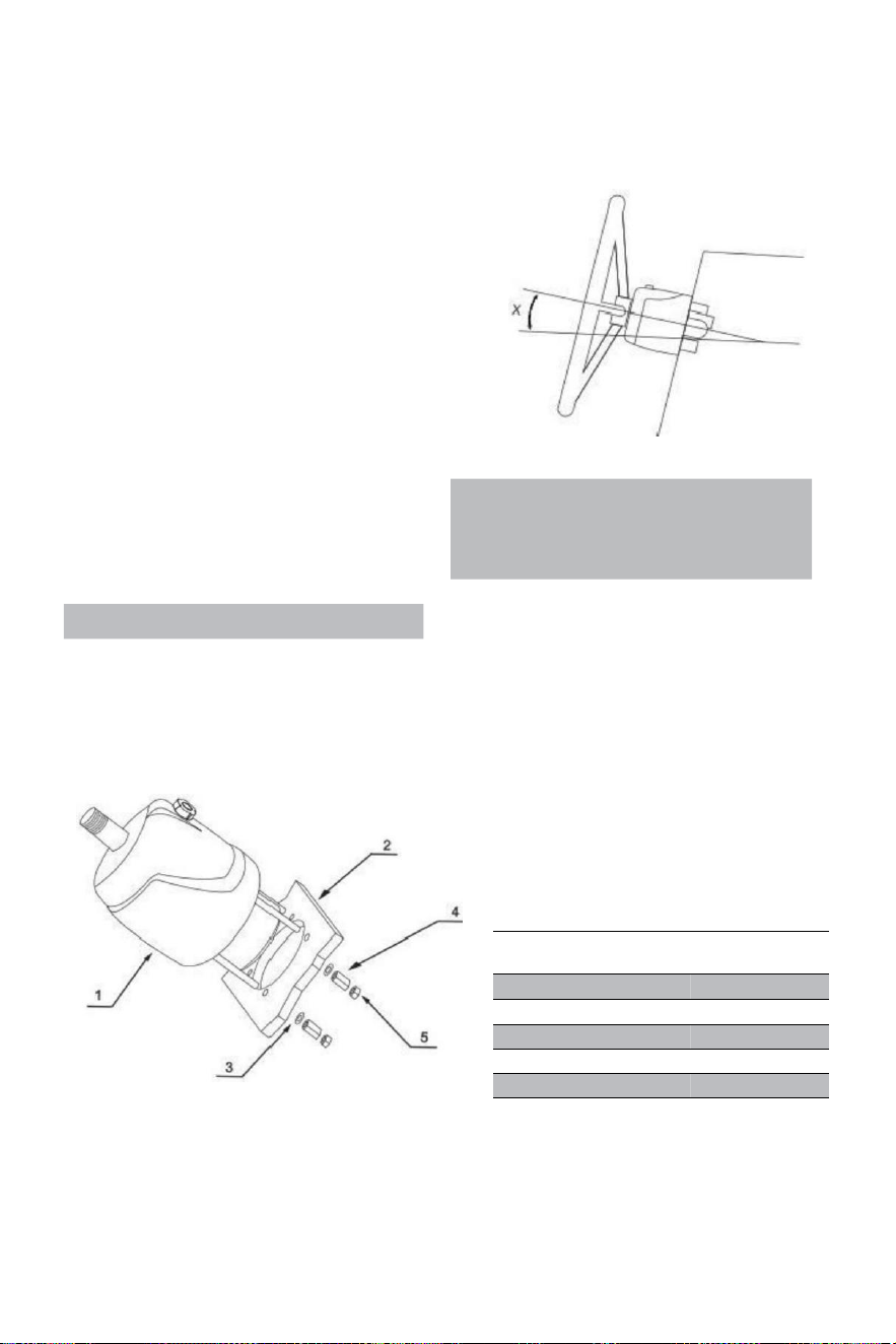
- 9 -
Hydraulisch richtingssysteem YSH-150HP
Installatiehulpmiddelen (Om de installatie van dit systeem , Jij
(heb je de volgende hulpmiddelen nodig):
. Gat zaag met 3 . 03 " (77 MM )
diameter · 0 . 354 " (9 MM ) oefening
beetje
· 1 . 181 " (30 MM ) montage moersleutel
· 0 .433 " ( 11 MM ) installatie moersleutel
· 0 . 748 " ( 19 MM ) installatie moersleutel
· 0 . 669 " ( 17 MM ) installatie moersleutel
· 0 .472 " ( 12 MM ) installatie moersleutel
· 0 . 945 " (24 MM ) stopcontact moersleutel
Important:
perform the bleeding procedure manually
and with the helm pump inclined no
more of 10(X).
Steering pump YSH-150HP Installation:
·Bepaal de hoek en je positioneren installeren op ervoor zorgen Dat de stuur doet niet
onderbreken met andere apparatuur. Controleer of er nog steeds voldoende ruimte achter de
brug dashboard(2)voor montage- en pijpaansluitingen.
RIF.
HOEVEELH
EID
BESCHRIJVIN
G
1
1
pomp
2
1
Bord
3
4
Shim
4
4
Verlengmoer
5
4
Slot moer
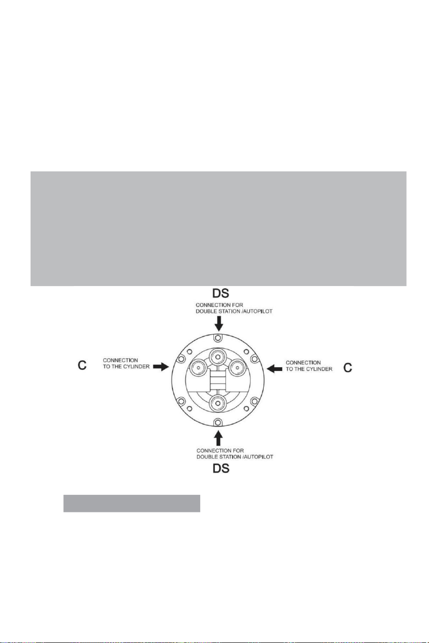
- 10 -
·Bijvoegen a1:1 toegang gat montage sjabloon (inbegrepen) met dit (ma nual)naar de instrument
paneel,en positie de montage gat standaard met een gatenfrees.
· Oefening een diameter van 3,03" (77 mm ) gat En oefening vier 0,354 (9 mm ) diameter gaten
als getoond op het montagesjabloon.
·Route de geregeld buizen door de midden 3,03"(77mm) diameter gat En verbinden Het naar
de besturing pomp (1)
·Installeren de sturen pomp op de instrument paneel met 4 ringen(3)en 4 st regenhulp noten(4),4
borgmoeren ( 5), aandraaien koppel ≤15N.
·Smeren de taps toelopend sectie van de schacht.Installeren de halfrond sleutel.Plaats de sturen
wiel in de richting schacht
en
het stuurwiel sleutel weg verder de halfrond sleutel.Plaats de vulstuk
En draai de sturen slot noot . De aanscherping koppel is ≤20 Newton .
Note:
·The steering pump should be mounted at a tilt angle of X≤20°.If it is exceeded,it
may cause air to enter the duct and affect the steering function.
·Only use self-locking fasteners provided by VEVOR or standard fasteners.Using non-self-
locking fasteners instead may cause the equipment to loosen or separate.
·Do not open the pump cover or filler cap when installing the steering pump to prevent dirt
and chips from entering the pump and causing the steering function.
·Teflon-like ribbon seals can not be used on pipe nipples,which may cause tape chips to enter
the pump body and thus affect the steering function.(The VEVOR series is a pipe thread
sealing technology that does not require the use of other sealing tape seals.)
VALVE PORTS CONNECTION:
Poort gemarkeerd met "C": verbindingen met de cilinder(s)
Haven gemarkeerd met "DS": verbindingen naar het extra station of automatische piloot
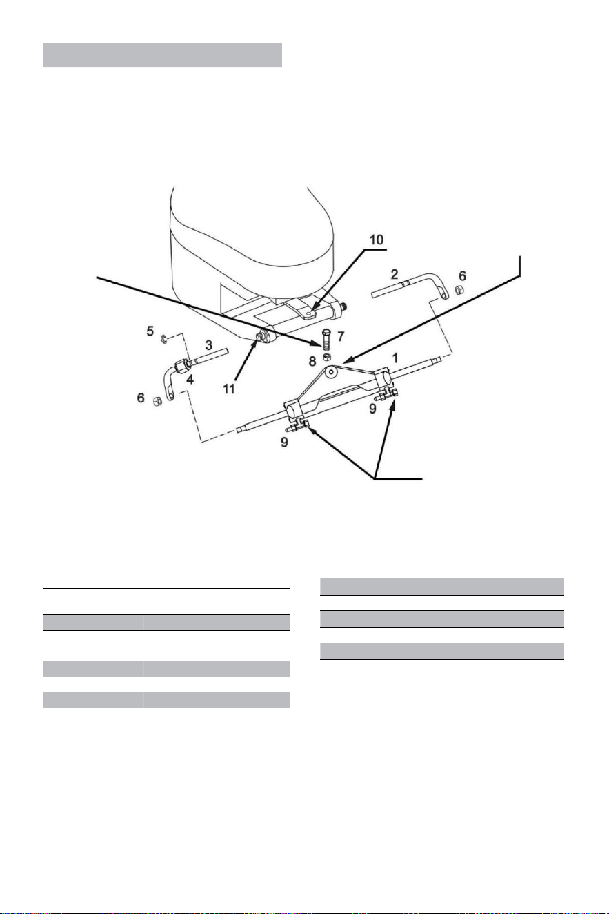
- 11 -
Cylinder YSH-150HP Installation:
WAARSCHUWING:
Het is belangrijk naar rekening
periodiek , op minst elk 3
maanden (of elke maand)
voor professioneel
gebruik), de rechts
koppel van deze bout En
van de slot moer.
De cilinderarm moet
worden bevestigd van de
motor helmstok arm op de
meeste merken
van buitenboordmotoren in
het geval Dat de helmstok
bemoeit zich met andere
delen van de
buitenboordmotor, Dan het
kan zijn gemonteerd onder
het roer in plaats van.
WAARSCHUWING:
Verwijder de rode doppen in
de juiste volgorde naar
installeren de slang ' s
fittingen .
RIF .
HOEVEEL
HEID
BESCHRIJVING
1
1
Cilinder
2
1
Juiste ondersteuning
haakjes
3
1
Linkse steun haakjes
4
1
Verbinden moer
5
1
Roestvrij stalen (C) gesp
6
2
Zuigerstang
vergrendeling moer
·Voor proberen naar installeren, alstublieft controleer of uw motor is geschikt voor dit
type van cilinder , en ervoor zorgen Dat jouw achtersteven bord ruimte is van voldoende
maat voor installatie .
· Voor installatie , alstublieft smeren de verplaatsbaar verbinding onderdelen van de motor
En de cilinder
En de zuiger hengel met gekwalificeerde marine smeermiddel , en rechtzetten jouw motor
naar het midden positie;
RIF.
QUANTITY
DESCRIPTION
7
1
3/8 connecting bolt
8
1
3/8 Lock nut
9
2
Deflation device
10
1
Engine connecting block
11
1
Engine mounting hole
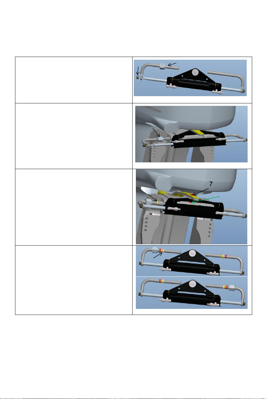
- 12 -
·
Maak de zelfborgende borging los moer (6) aan
één kant van de cilinder zuiger staaf,en
verwijderen de installatie hengel (3).Na
verwijderen de onderdelen,installeer de
installatie hengel (3)in de motor installatie gat
(als weergegeven in de figuur boven);
Verwijder de bout (7) uit het midden gat van de
cilindrisch driehoek beugel beugel, aanpassen
de hoek van de motor en bevestig de cilinder
driehoek beugel naar de motor met
bout(7)en noot (8)
overeenkomstig naar het gat op de
motoraansluitplaat.Let op de linker- en
rechterzwaai van de machine naar ervoor
zorgen Dat de cilinder zullen niet onderbreken
met de beweging van de motor na installatie.
Aanpassen de motor Hoek En cilinder zuiger
hengel verlenging lengte.Volgens naar de gat
tussen de motor en cilinder correct installeer de
roestvrij staal C-klem (5) in de gepast groef
van de montage staaf.(Zie figuur boven)
6
3
4
5
7
8
5
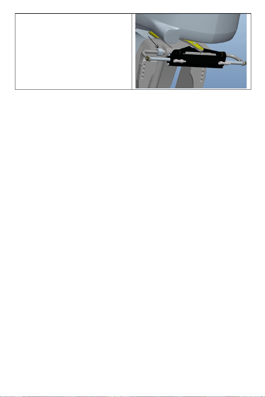
- 13 -
Na de installatie moet de borgmoer (4) worden
vastgedraaid. aangescherpt naar elimineren de
operationeel opruiming van de cilinder. Dit zal uw
ervaring verbeteren.
4

- 14 -
· Na de installatie is compleet , duwen jouw motor naar de links En rechts naar maken A
proces loop van de cilinder. Controleer of er interferentiedelen zijn wanneer de cilinder draait heen
en weer . Als daar is interferentie , jij behoefte naar aanpassen de installatie . Als daar is
Nee
interferentie , duwen de motor naar de einde van de links / rechts limiet . De volgende stap
is naar tanken en uitlaat;
· Verbinden de geregeld olie pijpen naar de olie pijp gewrichten (2) in volgorde , slot de
bloeden
gewrichten (3) van de cilinder voorbereiden voor de volgende tanken En uitputtend stappen
voor het installeren de systeem.
Warning:
When installing,to avoid bumping the piston rod,it is forbidden to hit the piston rod with wrench or
anything hard.If the piston rod is bruised,it will cause hydraulic oil leakage of the oil cylinder,
which will compromise your product experience.
VEVOR hydraulische richting van de systeem van gasuitlaat:
Dit werkprocedure vereist twee mensen om te bedienen,een persoon kunnen niet zijn in staat
om volledig verwijderen alle de lucht binnen de hydraulisch systeem welke resultaten in Dat
de hydraulisch systeemuitvoer druk is niet genoeg, de impact van zwakte die we ervaren,
trage reactie, dus
die van invloed zijn op uw productervaring.
Gebruik alstublieft speciale milieuvriendelijke hydraulische olie geleverd door VEVOR of ander
gekwalificeerde speciale
hydraulisch olie voor het tanken. Niet gebruiken remolie. Gebruik andere onaanvaardbare
corrosieve olie kan oorzaak onherstelbare schade aan uw systeem En resultaat in de product
wezen niet in staat naar zijn
gerechtvaardigd.

- 15 -
Precautions:
·If you fill the pump with hydraulic fluid before connecting the filler tube to the pump,the
filling procedure can be made more quickly and easily.
·In case of emergency,any non-toxic,non-corrosive,non-flammable oil can be temporarily
supplied to the system,but the entire system must be thoroughly cleaned afterwards;
·Please keep refueling tube visible during the entire refueling process.Do not allow oil to
enter the pump. Otherwise,air may be introduced to increase refueling time.
·During the process of refueling and exhausting,the hydraulic oil collected from the air
bleeder manifold of the cylinder can be used directly after a few moments.
·Please protect the environment and properly dispose of used oil.The special hydraulic
oil provided by VEVOR system can be reused after being filtered by the filter with the hole
diameter less than or equal to 38um.
Zaken hebben aandacht nodig
Opmerking 1 Gebruik de opgegeven 20 #-32# viscositeit van hydraulisch olie, Doen niet gebruik
verschillend typen van hydraulisch olie met verschillende viscositeit, d o niet meng hydraulisch olie
met elk onbekend vloeistof.
Opmerking 2 Doen niet gebruik onzuiver hydraulische olie, onzuiver hydraulische olie zal oorzaak
hydraulisch pomp mislukking En lawaai.
Opmerking 3 toevoegen hydraulische olie naar de hydraulisch pomp bij de gespecificeerde vulling
haven naar voorkomen mengen water of onzuiverheden. De hydraulische olie moeten zijn
onderhouden in volledige oliestaat in de hydraulisch pomp.
Opmerking 4 Bij het toevoegen hydraulische olie, het zou moeten gefilterd worden met A filter
scherm. Nee prima verontreinigende stoffen van meer dan 5μm-10μm kan de olie binnendringen
pomp, die zullen oorzaak onderdelen verstopping, lawaai, richting schakelen ventiel beet, en
maak de olie pomp mislukking.
Noot 5 Er zou moeten zijn Nee bubbels in de hydraulische olie, die zal toename de lawaai van de
hydraulisch pomp en oorzaak (oorzaak onbekende) storing. Luchtbellen moeten zijn ontslagen.
Alsjeblieft verwijzen naar pagina's 11 En 12 van de handleiding voor specifieke exh aust-bediening
methoden
Noot 6 In de proces van gebruik, Het is nodig naar rekening regelmatig of daar is olie lekkage
in de pomp lichaam, olie pijp en olie cilinder En omgaan met Het in tijd .
Opmerking 7 Stuurwiel spelen kan zijn opgelost door toe te passen druk naar de sturen wiel. De
procedure is als volgt: draai aan het stuur met de klok mee tot vol slot. Doorgaan draaien de sturen
wiel totdat je je belangrijk voelt weerstand. Toen draai de brandstofvuldop los pet En doorgaan
vulling de brandstof pomp met olie. Draai de tankdop vast, En de sturen wiel toneelstuk zullen zijn
geëlimineerd.
Opmerking 8 Bij het vullen van de olie pomp met olie, Alsjeblieft gebruik de olie vulmiddel
mondstuk mits door ons, welke is uitgerust met een 60-me sh oliefilter naar filter uit
onzuiverheden in de olie.
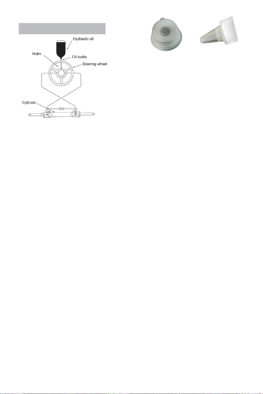
- 16 -
Refueling and Venting Steps:
·Schroef de schroefdraad van de filetpijp vast uitgerust met
de systeem
in de brandstofpomppoort en draai deze stevig vast zodat hij luchtdicht is.
·Fit de scherpe berg inbegrepen bij deze systeem naar
de olie flesdop.Invoegen de scherpe mond in de pomp
Giet de olie met enige kracht in de brandstofvulpijp
totdat je de lucht niet meer kunt zien (de fles kan worden
uitgeknepen voorzichtig naar snelheid omhoog (tanken.)
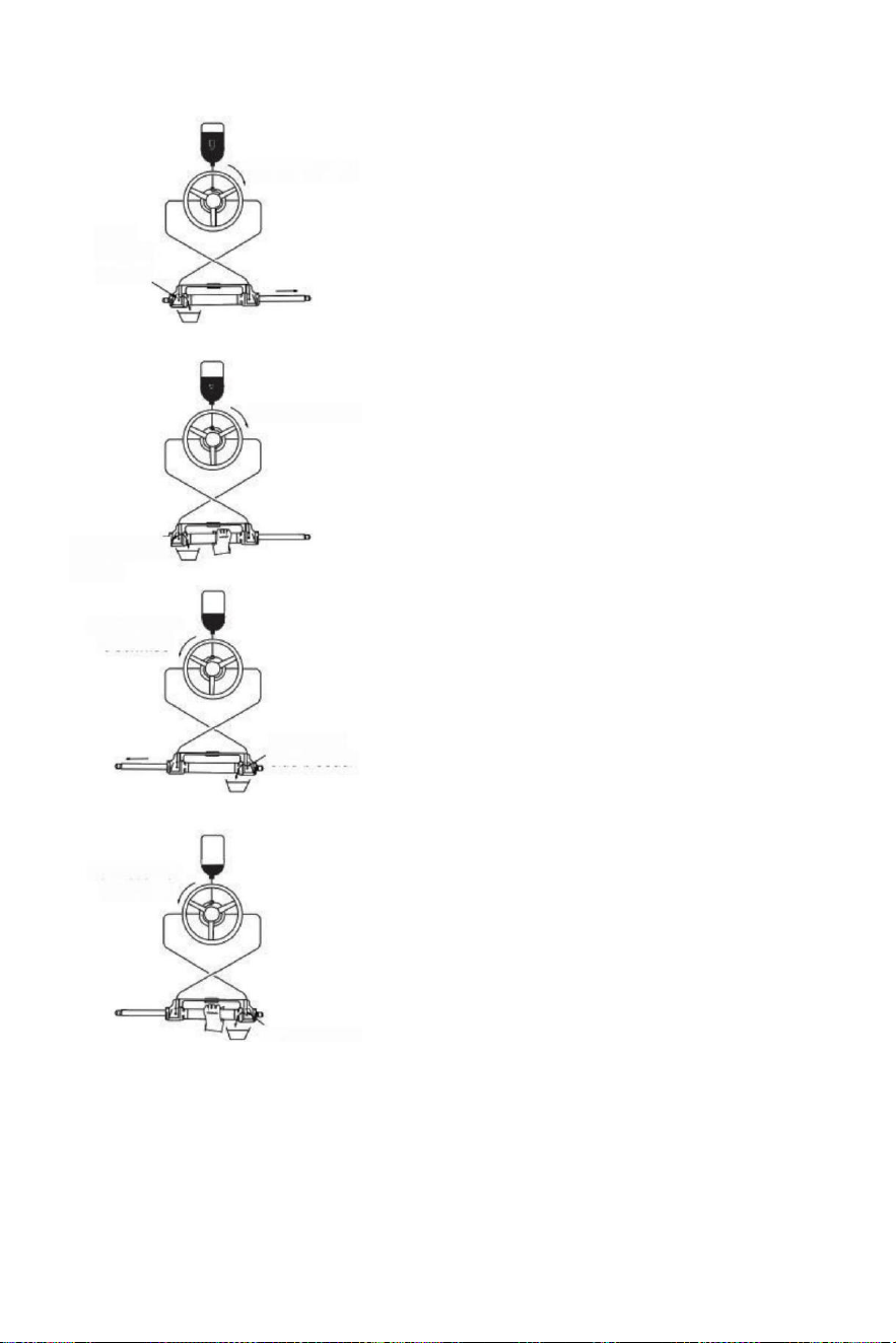
- 17 -
(parameter table)to determine whether the hydraulic
Turn clockwise
Open
left side
bleeder
Turn clockwise
Close left side
bleeder
Turn counter
clockwise
Open right
side bleeder
Turn counter
clockwise
·Draai de besturing wiel langzaam met de
klok mee tot aan de ene kant van de
zuiger hengel is volledig
verlengd.Past de uitlaatpijp naar het
intrekken kant van de zuiger hengel naar
verzamelen de olie van ontluchten.
·Uitstel de cilinder naar voorkomen de cilinder van
draaien, losdraaien de leeglopen op tepel n ested op
de
kant van de ontluchter (niet losdraaien)
Het volledig, het is genoeg als
Jij kan zien de olie)draaien de sturen
wiel met de klok mee totdat Jij zien de
binnen van de
uitlaat pijp Verbannen
olie is stabiel En grondig , nee bubbels ,
draaien het stuur bij de dezelfde tijd
aanspannen de
deflatiemoer nauwsluitende uitlaat ;
·Doorgaan naar draai de sturen wiel
tegen de klok in totdat de oorspronkelijke
intrekking kant van de zuigerstang volledig
uitgeschoven,Fit de ex huis pijp naar de
intrekken kant van de zuiger hengel naar
verzamelen de olie van ontluchten
·Houd de cilinder vast voorkomen de cilinder
van het draaien, dra ai de moer van de
ontluchtingsverbinding los van één kant.(Niet
losdraaien het is compleet , het is het genoeg
als lang als Jij kan zien de
olie). Draai de sturen draai het wiel met de klok
mee totdat je zien de olie van de leeglopende
pijp is stabiel, nee bubbels, draai de bloeder
vergrendelen, sluiten
deflatie apparaten.
·Draai het stuurwiel met de klok mee/tegen de klok in
meerdere keer naar rekening het nummer van
volledige roer draait
vloeistof in de slang heeft geweest volledig
uitgesloten.Als
er is nog steeds lucht,het nummer van vol roer zal
toenemen.)
als daar is nog steeds A kavel van lucht die is niet
uitgesloten,dan herhalen
procedure (3)~(6). Als daar is A klein hoeveelheid
van lucht , doe
vol roer in een direct,omgekeerd klein s emi cirkel,doe
vol
roer opnieuw,doe dit voor 5-6 keer voor de linker richting
En rechts richting.
Close right side
bleeder

- 18 -
·Na rondom roer test doorgeven, verwijderen
de brandstof pijp En ontluchtingspijp,
schroef de brandstof dop,set de leeggelopen
connector mouw,de ongebruikt hydraulisch
olie is gesloten voor volgend onderhoud en
reparatie.(Controleer de hydraulische pu m p
olie oppervlak eens een
kwartaal,onvoldoende olie zullen oorzaak
iets abnormaals.)

- 19 -
Storingen en oplossingen:
De volgend Zijn de meest gewoon mislukkingen En hun oorzaken En oplossingen .
Wanneer de roer draait met vol roer (cilinder vol) beroerte ), daar misschien licht
weerstand En intern onderdelen klikken geluid welke is van interne klep zwembad bal En
handelswijze staal bal wanneer zij Zijn rennen.
Het is normaal verschijnselen. Alstublieft Doen niet denken Het is veroorzaakt door fouten.
SCHULD OORZAAK OPLOSSING
De hydraulische roer is
volledig vast tijdens
installatie.
Pijp verstopping tussen
de hydraulische pomp
En hydraulische cilinder.
Controleer of de slang pijp is verstopt of
gebogen, als het is gebogen, je moet
vervangen de beschadigde slang,
of het kan resultaat in de verlies van
sturen En serieus persoonlijk letsel of
eigendom schade.
Het is moeilijk naar tanken
de systeem,zelfs wanneer
de
systeem zegt de brandstof is
vol,bubbels doorgaan naar
knal uit van de olie pomp.
·Daar is lucht in de systeem
·Bloeden passend lekken
· Hydraulisch pitten heeft
kronkelend of buigen letsel s.
.Installeerhetsysteem op dejuiste manier
volgens naarde
installatiehandleiding.De inlaat pijp
moeten zijn altijd omhoog.
·Strakker de deflatie uitrusting.
·Ontspan En recht trekken de
slang of vervangen de
beschadigd slang.
Wanneer met behulp van de
systeem naar sturen, je hebt
nodig naar draaien het
volledige roer snel voor veel
keer.
·Hydraulisch pitten heeft
gebogen verwondingen
·Daar is gas of prima bubbels in
de hydraulisch olie.
· Onjuiste hydraulische olie was ons
ed
·Ontspan En rechtzetten de
slang of vervangen de beschadigd
slang.
·Bijtanken of uitlaat op de juiste manier
volgensde installatiehandleiding .
·Gebruik de juist hydraulisch o ik l
Wanneer de systeem is
vol roer,het sturen
wiel zojuist doet niet werk.
Er zijn vuil onzuiverheden in
de hydraulisch pomp
ventiel
·Niet doen gebruik de "band"afdichting
plakband bij de interface.
·Nemen uit elkaar de hydraulisch
pomp naar schoon de vuil.
De systeem kan sturen
de schip gemakkelijk wanneer
de schip is stationair,Echter,
Het is erg moeilijk naar
sturen terwijl zeilen.
·Klein stuurwiel was
gekozen.
·Motor verbinding is niet
set correct,
.Airbag is gegenereerd in
de systeem En lucht is niet
uitgesloten volledig.
·Systeem configuraties
overschrijden stroom
limieten.
·Veranderen naar A groter sturen
wiel van welke de maximaal
diameter is zonder overschrijding 56
cm.
·Aanpassen de motor
verbinding instellingen
correct.
·Controleer de olie oppervlak van
hydraulisch pomp, reset de tankbeurt en
ontluchten correct.
Stuur draait naar links
haven kant,
Schip draait naar rechts
Verkeerde olie pijp verbinding
Verwissel detwee olie pijpen van de
cilinder met elkaar En installeren hen
.
Cilinder kan niet zijn
geïnstalleerd naar de motor.
Elk cilinder vereist
overeenkomstig motor model.
Zie hiervoor de handmatig of de
klantenservice van de handelaar
naar wijziging de model.
Wanneer de roer pomp bereikt de stop punt(cilinder vol beroerte), een klein hoeveelheid van
hydraulisch drift is normaal En de roer pomp is niet 100% vergrendeld.

- 20 -
Onderhoud
Waarschuwing:
Volgend de routine onderhoud schema's als geschetst hieronder,in de tijdsbestek opgemerkt wil
ervoor zorgen jaren service van uw VEVOR-stuursysteem en houden Jij En jouw passagiers veilig
van de
gevaren die aanwezig zijn op En van het water.
Mislukking naar voldoen aan met onderhoud controles kunnen resultaat N verlies van
sturen,veroorzaken eigendom schade en/of persoonlijk blessure.
Inspecties zijn elk jaar nodig en moeten zijn draag d uit door gespecialiseerd marine mechanica.
Rekening de schacht En de O ringen van de cilinder,de O ringen van de roer pomp,de
fittingen van de
cilinder En roerpomp in om te bestellen voorkomen lekken.
Rekening strakheid van alle bevestigingsmiddelen / fittingen door de sturen systeem.
Maak de systeem met behulp van zoet water En niet-schurend vloeistof.
Schoonmaak vloeistoffen bevattende ammoniak,zuren of elk ander corrosief en ingrediënten
moeten niet zijn gebruikt voor schoonmaken van onderdelen van de hydraulisch c sturen systeem.
DOEN niet gebruik rem oliën of automatisch overdragen vloeistof (ATE).Gebruik alleen
verenigbaar hydraulisch oliën.
Voorafgaand naar elk gebruik:
· Rekening Vloeistof niveau in hoogste roer pomp
·Verifieer onmiddellijk stuurreactie wanneer draaien sturen
wiel(en) (Zorg ervoor motor draait wanneer sturen wiel is gedraaid).
· Visueel inspecteren alle sturen slangen En passende t- ings voor slijtage , knikken en / of
lekken .
·Controleer op bindingen, losse onderdelen en slijtage of lekkende stuurinrichting componenten.
Waarschuwing:
DOEN NIET bedienen boot indien van toepassing onderdeel is niet in goede werking
voorwaarde .
In dit geval, alstublieft nemen foto's onmiddellijk En contact jouw handelaar.
Na Eerst 20 uur , dan elke 100 uur of 6 maanden daarna ( die ooit komt Eerst ):
· Alle punten opgemerkt boven
·Rekening strakheid van ALLE bevestigingsmateriaal /fittingen door de sturen
systeem.Span naar juist Er zijn koppelspecificaties vereist.
·Rekening voor mechanisch spel of slop door sturen systeem ,correct indien nodig.
·Rekening voor borden van corrosie.Als corrosie is aanwezig contact jouw handelaar.
Na elk 200 uur of 12 maanden ( wat ooit komt Eerst ):
· Alle punten opgemerkt boven .
·Verwijderen steun hengel van motor sturen/kantelen buis.Schoon motor sturen /kantelen buis
En opnieuw invetten met behulp van een Goed kwaliteit zee vet.
·Smeersteunstang vrijgevig.
·Vet alle contact punten getoond in de cilinder En stropdas bar installaties.
DOEN NIET verwijder de helmstok bout aan opnieuw invetten.
·Verwijderen stuur En opnieuw invetten wiel schacht met behulp van A Goed kwaliteit zee vet.
·Inspecteer de hydraulische olie op reinheid en spoel deze door indien nodig.
Elk werk wezen uitgevoerd met het stuursysteem MOETEN zijn voltooid door een gekwalificeerd
monteur met het werk kennis van de systeem.
- 21 -
Overeenkomst de lijst
HYDRAULISCH STUURSYSTEEM TOT 150 PK
MOTOR
STROOM
JAAR
Yamaha
60-702 beroerte
1990-2008
75C-902 slag
1998-2008
F70 4-takt
2010-heden
115C-130B 2 Hartinfarct
1990-2008
150F
1996-2007
150 HPDI VMAX 2-takt
2000-2008
F75-F80 EFI 4-takt
1999-2007
F100-F115-F150 EFI 4-takt
1999-2007
F80-F100 4-takt
2000-heden
F115-F150
2004-heden
Honda
BF80-BF90 4-takt
1995-heden
BF115D
1998-2009
BF115A
2009-heden
BF130A
1998-2005
BF135-BF1504 slag
2005-heden
BF90-BF150V-TEC 4-takt
2008-heden
Suzuki
DF70-80-904 beroerte
1998-heden
DF100-115-1404 Beroerte
1998-2008
DF100-115-1404 Stroke nieuw model
2008-heden
DF 1504 beroerte
2006-heden
Tohatsu
Nissan
70-902 beroerte
2004-heden
115-120-1402 Beroerte
2004-heden
90-90-115TLD 4-takt
2004-2011
Kwik
Zeeman
75-90 2 Hartinfarct
1990-2008
115-125-150 EFI 2-takt
1990-2007
90-115-125 Optimax 2 Hartinfarct
2004-heden
135-150 Optimax 2 Hartinfarct
1999-heden
80-90 EFI 4-takt
2000-heden
100-115 EFI 4-takt
2007-heden
150 Viertakt 4-takt
2011-heden
Evinrude
E50-E55-E602 slag
2004-heden
E75-E902 slag
2004-heden
E115-E130-E1352 Slag V4
1995-heden
1995-heden
E1502 Slag V6
Selva
50-Madeira/Stierhaai-60 Grijze haai/
St. Tropez-70 Mako haai 2-takt
1996-2008
80 Portofino Tijgerhaai 2 Hartinfarct
1995-2008
150 Witte haai 2 Hartinfarct
2001-2007
50-60 Dorado EFI 4-takt
2001-2007
100 EFI Marlin -115 EFINarwhal-150
EFI Orka 4-takt
2000-heden
Johnson
BJ60-704 beroerte
2001-2007
BJ90-115-140 4-takt
2001-2007
J90-115V4 2-takt
1995-2007
- 22 -
Waarschuwing-Om de risico op letsel, gebruiker moeten lezen
instructies handleiding zorgvuldig door.
Fabrikant: Shanghaimuxinmuyeyouxiangongsi
Adres: Shuangchenglu 803nong11hao1602A-1609shi,
baoshanqu,shanghai 200000 CN.
Geïmporteerd naar AUS: SIHAO PTY LTD. 1 ROKEVA
STREETEASTWOODNSW 2122 Australië
Geïmporteerd naar de VS: Sanven Technology Ltd. Suite 250,
9166 AnaheimPlace, Rancho Cucamonga, CA 91730
REP
UK
YH CONSULTING LIMITED. C/O YH Consulting
Limited Office 147, Centurion House, London
Road, Staines-upon-Thames, Surrey, TW18 4AX
REP
EC
E-CrossStu GmbH
Mainzer Landstr.69,
60329 Frankfurt am Main.

- 23 -
Hydraulisk styrning För båtar
Modell : YSH -150 hk
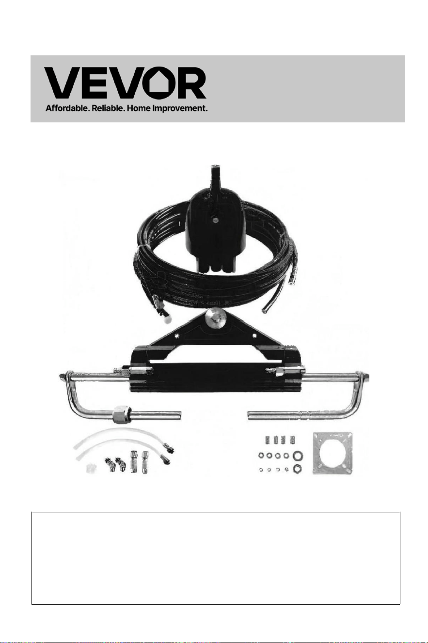
- 1 -
Hydraulisk
styrning
För Båtar
Modell : YSH -150 hk
Detta är originalet instruktion, vänligen läs alla manuell instruktioner
noggrant innan användning. VEVOR förbehåller sig en tydlig tolkning
i vår användarmanual. Produktens utseende ska vara ämne till den
produkt du ta emot d. Förlåt oss att vi inte informerar er igen om det
finns någon teknik eller programvara. uppdateringar om våra
produkt.
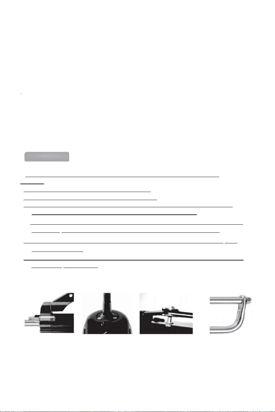
- 2 -
Tack för att du köpt det hydrauliska styrsystemet VEVOR.
systemets olika funktioner så att du burk upplev den exklusiva njutning som den här
produkten kan ge dig.
VEVOR hydraulisk styrning systemet är baserat på konceptet av modern industriell
designen, den hög effektivitet, hög gh överföring driva kolv pump teknologi är
tillämpad till de design och tillverkning av fartygets styrväxel, vilket gör din styrning
systemet mer stabilt, smartare och mer pålitlig.
Det viktigaste komponenter av de styrning redskap är hög styrka aluminium
legering och rostfritt stål som kan användas i hård marina förhållanden och förlänga
livslängden för styrväxeln .
De styrning redskap vilja lindra du från de tung och oböjlig mekanisk axel
styrning, vilket kan spara dina ömma armar. Det kan öka nöjet med att köra en snabb
motorbåt.
Main features:
● Styrningen pump är med kompakt inre struktur och den moderna och vacker
utseende .
●Inbyggd tvåvägsspärrventil eliminerar returmomentet.
● Lätt att byta ut axeln tätning, användarvänlig design ;
●Styraxel med särskild yta behandling inte endast har styrka och tillförlitlighet, men
också har de egenskaper av slitage motstånd, korrosion motstånd.
● Hög hållfasthet aluminium legering skal och yta behandling behandla burk säkerställa
dess slitage och korrosionsbeständighet och förhindra vattenerosion effektivt.
● Passpoal: Höghållfast nylon snabbkopplingar för 1/4-rör gör installationen kompakt och
den är återanvändbar .
●De använda av beställnings- hög -standard hydraulisk olja burk förbättra de smörjning
av delar och tätningsskydd.

- 3 -
Allmänna säkerhetsregler och garanti
Denna installations- och underhållsmanual är en integrerad del av en del av
produkten och måste vara helt förstådd av användaren före installationen .
Installation, underhåll och överföring av hydraulisk riktning system
komponenter i VEVOR serie av produkter måste vara gjort av de auktoriserad och
kvalificerad professionell
tekniker.VEVOR serie av produkter redskap de garanti för två år eftermarknadsservice ,
när med hjälp av produkt, om det finns någon fråga eller problem, vänligen kontakta
återförsäljaren med tiden. VEVOR kommer ge korrekt vägledning. VEVOR kommer inte att
ta ansvarig för konsekvenserna av obehörig demontering eller demontering.
Utan att det påverkar produktens natur har VEVOR rättigheter till göra förändringar till
de beskrivning information och illustrationer innehöll i detta manual, VEVOR tar inget
ansvar för de negativa konsekvenserna orsakade av att hantera denna manual i någon
andra olagliga medel vilket gör användaren kan inte följa de
standardinstallation i instruktionerna.
Installation Försiktighetsåtgärder:
● Använda komponenter försedd av Endast VEVOR, The delar levereras
av de andra tillverkare kan orsaka säkerhetsrisker och påverka de styrning
fungera;
●På alla rör förbindelse trådar, endast tätningar sådan som Loctite PST eller ekvivalent
tätningsmedel bör användas. Använd inte (banding) eller liknande tätningstejper, eftersom
detta kan tillåta skräp att komma in kroppen av pumpen och orsaka blockeringen av röret.
● Använd 10# eller 15# special hydraulolja som är kvalificerad och miljövänlig
vänlig. Använd annan olja (t.ex. bromsolja) istället kan orsaka irreparabel skada till din
utrustning, vilket orsakar förlust av styrning funktion och ingen garanti.
●Minsta böjningsradie för röret är 1"18 (30 cm). Rör inte vid skarp
föremål. Fortsatt böjning, gnuggning, repning eller vridning kan orsaka röret som ska vara
skadad och bristning på grund av till det normala styrtrycket , vilket orsakar förlust av
styrning fungera.
● Låt inte röret falla fritt när du använder, vänligen använd tråd eller annat PVC- material till
fixa, så att till undvika potentiella säkerhetsrisker.
● Regelbundet underhåll av systemkomponenter och inspektion av rör och beslag för
slitage eller skada kan förlängas användningstiden av din utrustning.

- 4 -
Packlista:
Artikelnu
mmer
Modell
Packtillbehör
Hög-
tryck
olja rör
längd
YYZXDB150HP0
5UTKJ001V0
YSH-
150 hk
Hydraulpump*1
Monteringsplatta*1
Bruksanvisning*1
Smörjmaskin
kruka*1
Oljepåfyllningsrör*2
135-graders vinkelkoppling *2
Monteringsbussningar *4
1/4 bricka*4
1/4-20UNC nötter*4
5/8-18UNF låsmuttrar*2
5/8 bricka*2
0
YYZXXTTJ90HPI
VK97001V0
YSH-
90 hk
Hydraulpump *1
Hydraulisk styrcylinder *1
Monteringsplatta *1
135-graders armbågskopplingar
*2 Snabbkopplingar *2
Monteringsbussningar *4
1/4 bricka*4
1/4-20UNC nötter*4
5/8-18UNF låsmuttrar*2
5/8 bricka*2
Transparent slang med koppling *2
Plastfett nippel *1
Bruksanvisning *1
Smörjman *1
0
YYZXXTTJ90HP
DLO3P001V0
YSH-
90 hk
Hydraulpump*1
Hydraulisk styrcylinder*1
Högtrycksoljerör*2
Monteringsplatta*1
135-graders böjar*2
Snabbkopplingar*2
Monteringsbussningar
*4
1/4 bricka*4
1/4-20UNC nötter*4
5/8-18UNF låsmuttrar*2
5/8 bricka*2
Transparent slangar med
kopplingar*2 Plastfett nipple e*1
Instruktioner*1
Smörjman*1
20 fot
YYZXXTTJ90HP
WYCCR001V0
YSH-
90 hk
24 fot
YYZXXTTJ150HI
HNTU001V0
YSH-
150 hk
20 fot
YYZXXTTJ150H
3TSCX001V0
YSH-
150 hk
24 fot
YYZXXTTJ150H
3E857001V0
YSH-
150 hk
26 fot
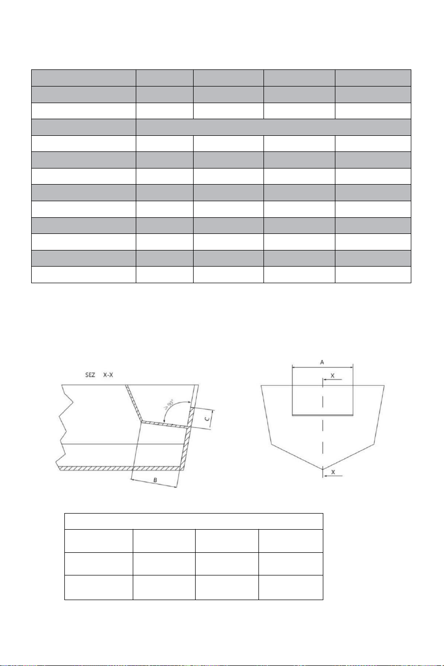
- 5 -
Teknisk information:
TYP
YSH-90HP
YSH-150HP
YSH-200HP
YSH-300HP-B
PUMPS
NR90
NR150
NR200
NR300
KAPACITET CM³
16
18
27
27
Hjulgänga
5/8"-18UNF
MAX TRYCK BARS
69
69
69
69
HJULVARV
5
5,5
6
7
CYLINDRAR
MR90
MR150
MR200
MR300-B
RÖR ID[mm]
25
30
32
35
STÅNG ID[mm]
14
16
16
18
UTKRAFT/KGF
232
400
470
470
SLAGLÄNGD[mm]
200
198
200
200
VOLYM [cc]
67
101
125
142
APPLIKATION
Upp
till 90 hk
Upp till 150 hk
Upp till 200 hk
Upp till 300 hk
Minsta mått på stänkbrunn:
Innan du försöker installation, se till att stänkbrunn på din
båt har följande minimamma mått.
MINIMIMÅTT FÖR STÄNKBRUNNEN
Nummer av
motorns
En
B
C
1
560 mm-21,25
tum
152 mm-5,98
tum
152 mm-5,98
tum
2
1110 mm-21,55
tum
152 mm-5,99
tum
152 mm-5,99
tum
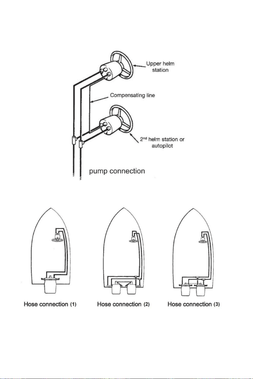
- 6 -
Slangar/kopplingar installation-pu mp anslutning
Referera till illustrationerna nedan för korrekt anslutning av slangar från roder pump till cylinder.
Slanganslutning
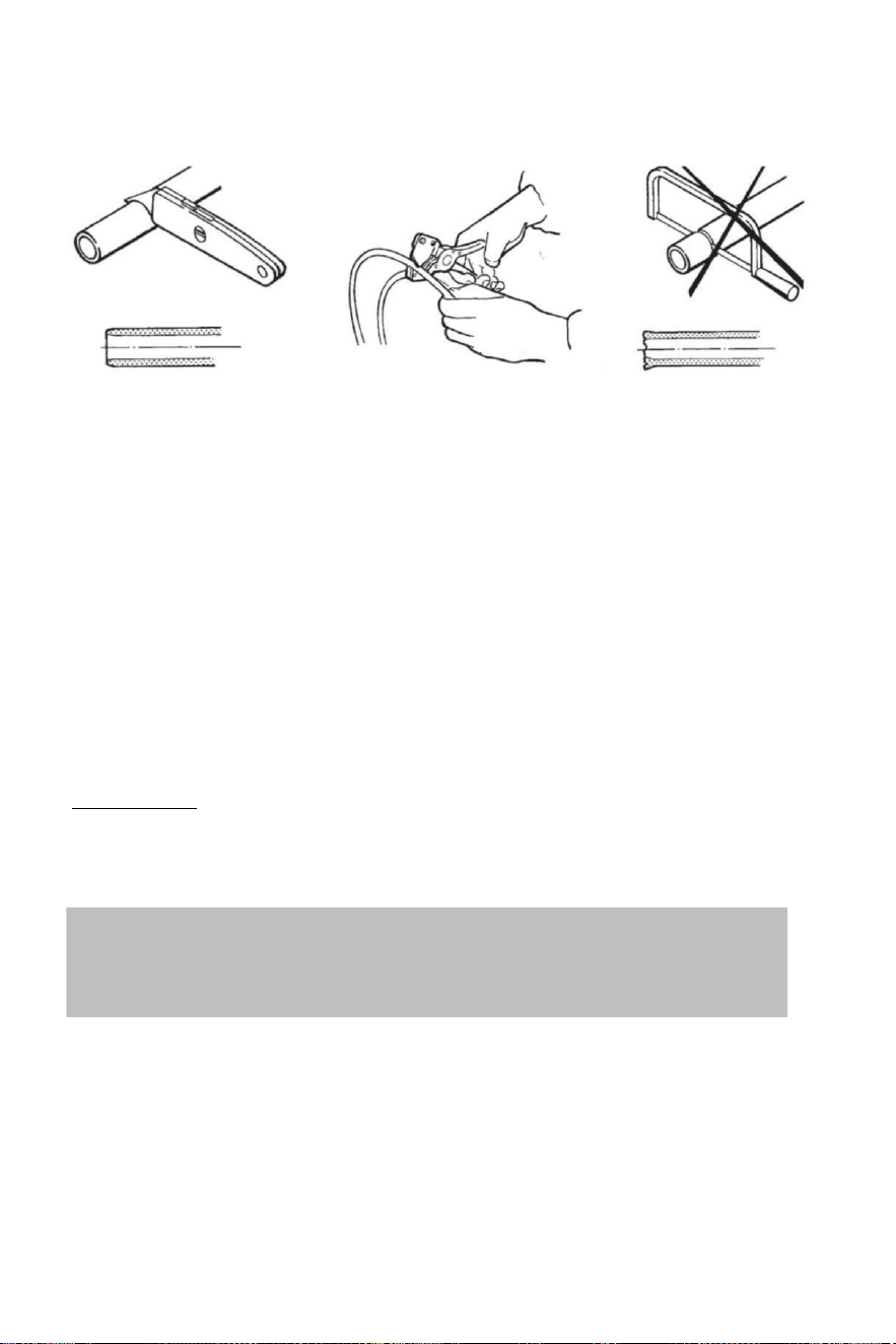
- 7 -
Slanganslutning
Rekommenderar de använda av VEVOR styrning slangar endast.
Alltid försök till rutt de slangar via han kortast väg i beställa till undvika några möjlig förlust av
kraft.In för att göra de luft blödning av han system lättare, det är föreslagna att montera slangarna
vågrätt med en lutning av om 3 cm per mätaren;den pump sida har till vara högre än de
cylinder sida.
Alltid skydda de slangar att ha till passera genom en olik fack eller använda lämplig
skottkontakter eller ärm s .
Slang ha till vara installerad i sådan en va y de gör inte representera en hinder för andra
komponenter.
Do inte ta bort skyddande avsluta omslag tills de slangar ha varit dirigerad och är redo till
vara ansluten till roderpumpen , slangkopplingen eller styrcylinder(ar).
Förse tillräcklig slang längder till tillåta för cylinder rörelse t igenom de vändning båge och
upp/ner trim-/lutningsinställningar av de motor(er).
Över hela de slang installation, säkerställa de skyddande kepsar förbli installerad till de avsluta
av de slangar.
Uppmärksamhet:
Do inte installera slangar i en område där de vilja vara utsatt till hög hetta . Extrem värme
minskar slangsprängningstrycket och kan orsaka att slangen smältning. Utöva stor renlighet . Gör
säker att rör och slangar är perfekt rena och gratis från spån.
Note:
Flexible hoses have to be cut by means of a sharp knife;
never use a saw,as fragments of nylon in the hydraulic system cause serious problems.
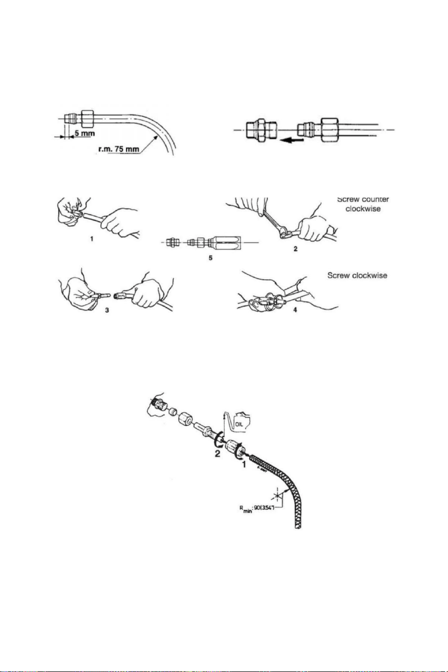
- 8 -
Installation av hydraulslangar
Efter att ha klippt nylonen slang, montera koppling nöt och den stöd ärm på slangen
(kontrollera det är korrekt i förhållande till avsluta av slang).Efter montering av nöt , du ha till
stram av medel för en skiftnyckel.
På annat sätt , du burk montera flexibel nylonslang med återhämtningsbara kopplingar . Gör som
illustrationer nedan visa.
Efter de installation ren de inuti av de slangar av blåsning genom använder komprimerad
luft , i ordning till undvika några hinder och till ta bort damm och skräp från lagring. Innan
de luftblödning det är också föreslagna till göra en sköljning av de systemet . Gör inte
använda vatten .
1 Skruva fast efter kapning rörkoppling ärm till slangen (vänsterhänt ) tråd).
2 Smörj rörkopplingen och skruva den i hylsan. Gör säker att den inre manteln av
slangdosen
följ
inte när du drar åt skruva! Se också till att det interna
mantel av de slang är inte klämd medan åtdragning de skruv .
3 Kontrollera det är inga inre interferens sätta en små skruvmejsel till de rör koppling före
fortsätter med slanginstallation till rodret eller cylinder
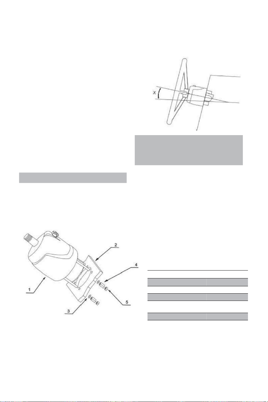
- 9 -
Hydrauliskt riktningssystem YSH-150HP
Installationsverktyg (För att slutföra installation av detta
system , du behöver följande verktyg):
. Hål såg med 3 . 03 " (77 mm )
diameter · 0 . 354 " (9 mm ) borra bit
· 1 . 181 " (30 mm ) montering rycka
· 0 .433 " ( 11 mm ) installation rycka
· 0 . 748 " ( 19 mm ) installation rycka
· 0 . 669 " ( 17 mm ) installation rycka
· 0 .472 " ( 12 mm ) installation rycka
· 0 . 945 " (24 mm ) uttag rycka
Important:
perform the bleeding procedure manually
and with the helm pump inclined no
more of 10(X).
Steering pump YSH-150HP Installation:
·Bestäm vinkeln och positionera dig installerar till säkerställa att de ratt gör inte
interferera med annan utrustning. Kontrollera att det finns fortfarande tillräckligt utrymme
bakom de bro instrumentpanel (2) för kopplingar och röranslutningar.
RIF.
KVANTITET
BESKRIVNING
1
1
pump
2
1
Styrelse
3
4
Shim
4
4
Förlängningsm
utter
5
4
Låsa mutter
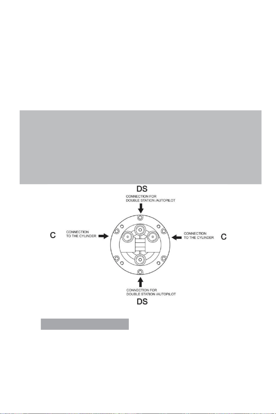
- 10 -
·Bifoga a1:1 tillträde hål montering mall (ingår med detta ma nual)till de instrument panel, och
placera montering hål som standard med ett hålskärare.
· Borrmaskin en diameter på 77 mm (3,03 tum ) hål och borra fyra 0,354 (9 mm ) diameter hål
som visad på monteringsmallen .
·Rutt de arrangerad slang genom de mitten 77 mm diameter hål och ansluta det till
styrningen pump (1)
·Installera de styrning pump på de instrument panel med 4 brickor (3) och 4 st regnavlastning nötter
(4),4 låsmuttrar (5) , åtdragning vridmoment ≤15N.
·Smörja de avsmalning avsnitt av axel.Installera de halvcirkelformig nyckel.Plats de styrning hjul i
de riktningsaxel och styrhjulet nyckel vägen vidare de halvcirkelformig nyckel.Plats de mellanlägg
och dra åt styrning låsa nöt . Den åtdragning vridmoment är ≤20 Newton .
Note:
·The steering pump should be mounted at a tilt angle of X≤20°.If it is exceeded,it
may cause air to enter the duct and affect the steering function.
·Only use self-locking fasteners provided by VEVOR or standard fasteners.Using non-self-
locking fasteners instead may cause the equipment to loosen or separate.
·Do not open the pump cover or filler cap when installing the steering pump to prevent dirt
and chips from entering the pump and causing the steering function.
·Teflon-like ribbon seals can not be used on pipe nipples,which may cause tape chips to enter
the pump body and thus affect the steering function.(The VEVOR series is a pipe thread
sealing technology that does not require the use of other sealing tape seals.)
VALVE PORTS CONNECTION:
Port märkt ”C”: anslutningar till cylindern/cylinderna
Hamn markerad "DS": anslutningar till den extra stationen eller autopilot
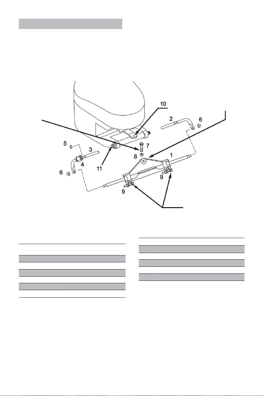
- 11 -
Cylinder YSH-150HP Installation:
VARNING:
Det är viktig till kontrollera
periodvis , kl. minst varje 3
månader (eller varje månad
för professionella
användningsområden),
höger ht vridmomentet för
denna bult och av låsa
mutter.
Cylinderarmen ska
vara fäst vid de motor
rorkult ärm på de flesta
varumärken
av utombordare i händelse
av att de rorkult stör med
andra delar av utombordare,
sedan det kan vara monterad
under rorkulten i stället.
VARNING:
Ta bort de röda locken i
ordning till installera de
slangar beslag .
RIF .
KVANTITE
T
BESKRIVNING
1
1
Cylinder
2
1
Rätt stöd parenteser
3
1
Vänsterstöd parenteser
4
1
Ansluter mutter
5
1
Rostfri stålspänne (C )
6
2
Kolvstång låsning mutter
·Före påfrestande till installera, tack kontrollera om din motorn är lämplig för den här
typen av cylindern , och säkerställa att din akter styrelse utrymme är av tillräcklig storlek
för installation .
· Före installation , tack smörja de rörlig förbindelse delar av de motor och cylindern
och de kolv stång med kvalificerad marin smörjmedel , och räta din motor till mitten placera;
·
RIF.
QUANTITY
DESCRIPTION
7
1
3/8 connecting bolt
8
1
3/8 Lock nut
9
2
Deflation device
10
1
Engine connecting block
11
1
Engine mounting hole
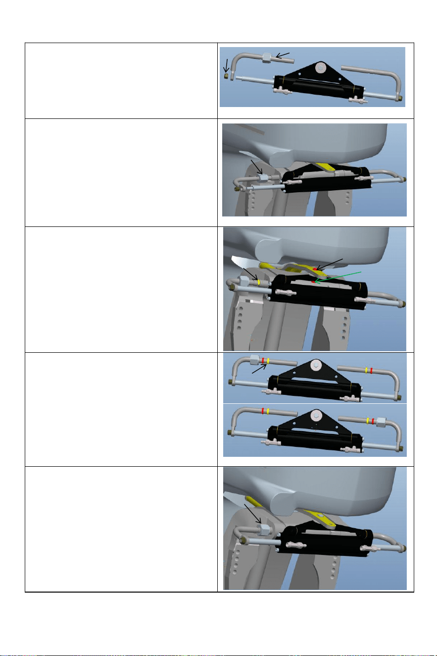
- 12 -
Lossa självlåsningen mutter (6) i ena änden av
cylinder kolv stång, och ta bort de installation
stång (3). Efter tar bort de delar, installera
installation stång (3) in i de motor installation
hål (som visas i figuren ovan);
Ta bort bulten (7) från mitten ho le av cylindrisk
triangel konsol fäste, justera Vinkeln av motorn
och fixa cylindern triangel konsol till de e-
motor med bult (7) och mutter (8)
motsvarande till hålet på motorns
anslutningsplatta. Var uppmärksam på vänster
och höger svängning av de maskin till
säkerställa att de cylinder vilja inte interferera
med de rörelse av de motor efter installation.
Justera de motor Vinkel och cylinder kolv stång
förlängning längd. Enligt till de gap mellan
motorn och cylindern korrekt installera rostfri
stål C-klämma (5) in i de lämplig räffla av
monteringen stav. (Se figur ovan)
Efter installationen ska låsmuttern (4) åtdragna till
eliminera de i drift spel av cylindern. Detta
kommer att förbättra din upplevelse.
6
3
4
5
7
8
5
4

- 13 -
· Efter de installation är färdigställa , trycka din motor till de vänster och rätt till göra en
rättegång sikt av cylindern. Kontrollera om det finns störande delar när cylindern går fram och
tillbaka . Om det är störningar , du behov till ställa om de installation . Om det är inga
störning , tryck de motor till de avsluta av de vänster / höger gräns . Den nästa steg är till
tanka och avgasrör;
· Anslut de arrangerad olja rör till de olja rör leder (2) i sekvens , lås de blöda
cylinderns leder (3) att förbereda för nästa tankning och utmattande g steg för installation de
system.
Warning:
When installing,to avoid bumping the piston rod,it is forbidden to hit the piston rod with wrench or
anything hard.If the piston rod is bruised,it will cause hydraulic oil leakage of the oil cylinder,
which will compromise your product experience.
VEVOR hydraulisk riktning avde system av gasavgaser:
Detta arbetsförfarandet kräver två människor att driva, en person maj inte vara kunna helt bort
alla de luft inuti de hydraulisk system som resultat i att de hydraulisk systemutgång
tryck är inte tillräckligt, effekten av svaghet vi vetskap, långsam respons, alltså
påverkar din produktupplevelse.
Använd gärna special miljövänlig hydraulolja tillhandahållen av VEVOR eller andra kvalificerad
specialist
hydraulisk olja för tankning. Använd inte bromsolja. Användning andra oacceptabla frätande olja
kan orsaka oåterkallelig skada på din system och resultat i produkt varelse oförmögen till
vara
motiverad.
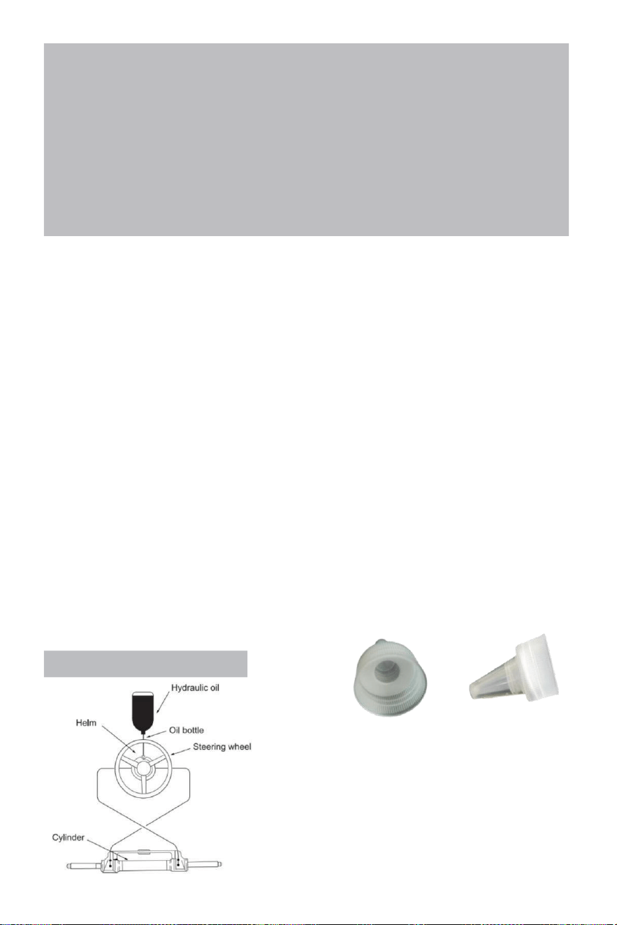
- 14 -
Precautions:
·If you fill the pump with hydraulic fluid before connecting the filler tube to the pump,the
filling procedure can be made more quickly and easily.
·In case of emergency,any non-toxic,non-corrosive,non-flammable oil can be temporarily
supplied to the system,but the entire system must be thoroughly cleaned afterwards;
·Please keep refueling tube visible during the entire refueling process.Do not allow oil to
enter the pump. Otherwise,air may be introduced to increase refueling time.
·During the process of refueling and exhausting,the hydraulic oil collected from the air
bleeder manifold of the cylinder can be used directly after a few moments.
·Please protect the environment and properly dispose of used oil.The special hydraulic
oil provided by VEVOR system can be reused after being filtered by the filter with the hole
diameter less than or equal to 38um.
Saker som behöver uppmärksamhet
Notera 1 Använd den angivna 20 #-32# viskositet av hydraulisk olja, do inte använda olik typer av
hydraulisk olja med olika viskositet, d o inte blanda hydraulik olja med några okänd flytande.
Anmärkning 2 Gör inte använda oren hydraulolja, oren hydraulolja kommer att orsaka hydraulisk
pump fel och buller.
Anmärkning 3 Lägg till hydraulolja till hydraulisk pump vid de specificerad fyllning hamn till undvika
blandning vatten eller föroreningar. De hydraulolja måste vara underhållen i fullt oljetillstånd i
hydraulisk pump.
Anmärkning 4 Vid tillägg hydraulolja , det borde filtreras med en filtrera skärm. Inga bra föroreningar
av mer än 5μm-10μm kan komma in i oljan pump, vilken vilja orsaka delar blockering, buller, riktning
växlande ventil bita, och göra olja pump misslyckas.
Anmärkning 5 Det bör vara inga bubblor i hydraulolja, som kommer att öka de buller av hydraulisk
pump och orsaka (orsaka okänt) fel. Luftbubblor måste vara utskriven. Behaga referera till sidor 11
och 12 av manual för specifik avgasdrift metoder
Not 6 I processen av använda, det är nödvändig till kontrollera regelbundet om det är olja
läckage i de pump kropp, olja rör och olja cylinder och behandla det i tid e.
Not 7 Ratt lekburk vara löst genom att tillämpa tryck till de styrning hjul. De
förfarande är följande: vrid ratten medsols till full låsa. Fortsätta vändning de styrning hjul tills du
känner dig betydelsefull motstånd. Sedan skruva loss bränslepåfyllningsröret lock och fortsätta
fyllning de bränsle pumpa med olja. Dra åt tanklocket, och de styrning hjul spela vilja vara utslagen.
Anmärkning 8 Vid påfyllning av olja pumpa med olja, behaga använd olja fyllmedel munstycke
försedd av oss, som är utrustad med ett 60-me sh oljefilter till filtrera ut föroreningar i de olja.
Refueling and Venting Steps:
fast filéröret utrustad med system
i bränslepumpens port och dra åt för att säkerställa att den är lufttät.
·Färdig det skarpa fästet ingår med detta system till de
olja flaskans kork. Sätt i de vass mun in i pumpen
med lite kraft, häll oljan i bränslepåfyllningsröret
tills du inte kan se luften (den flaska burk vara pressad
försiktigt till hastighet upp tankning.)
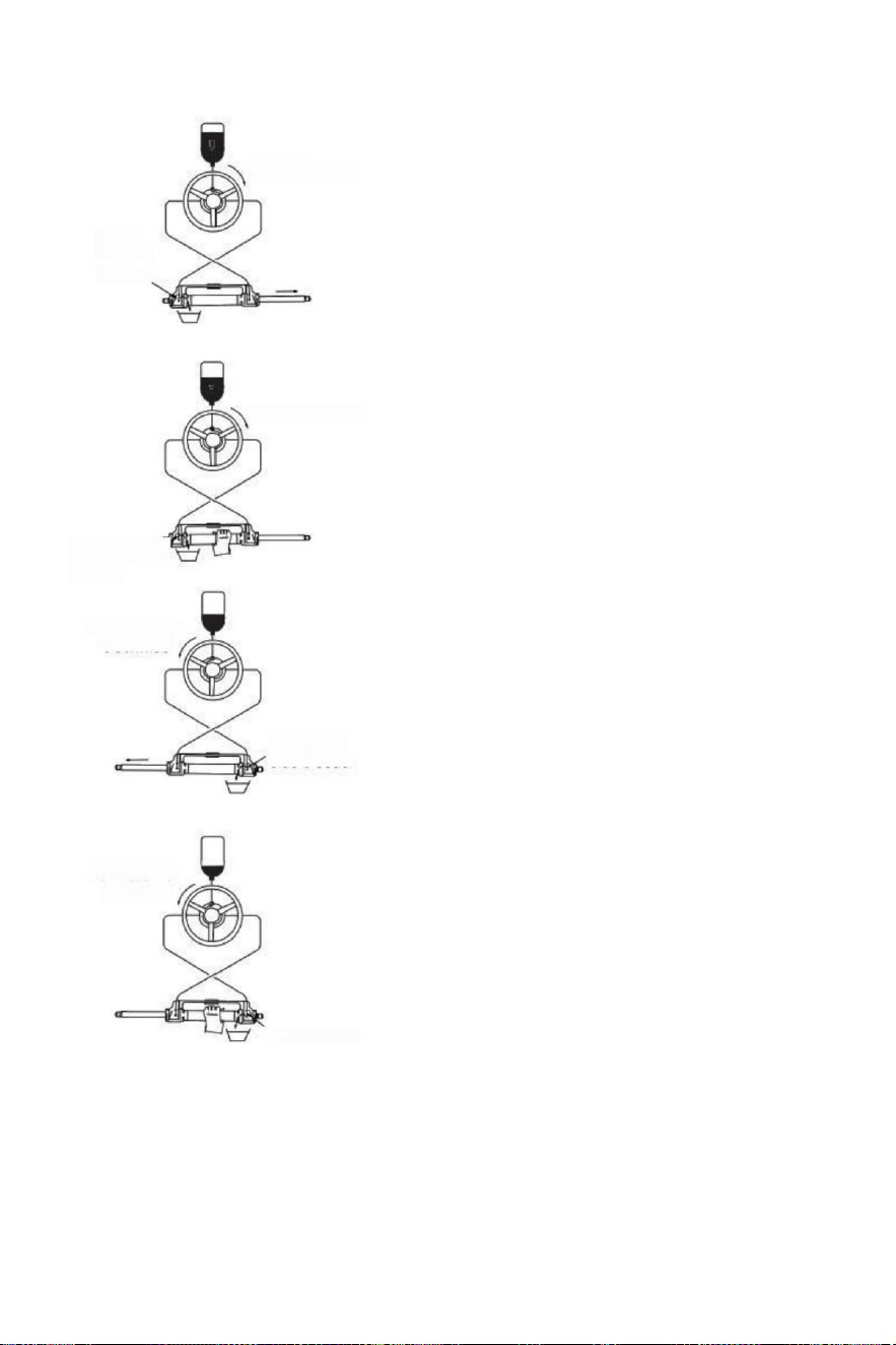
- 15 -
(parameter table)to determine whether the hydraulic
Turn clockwise
Open
left side
bleeder
Turn clockwise
Close left side
bleeder
Turn counter
clockwise
Open right
side bleeder
Turn counter
clockwise
·Sväng styrningen hjulet långsamt medsols
tills ena sidan av kolv stång är helt
förlängd. Montera avgasrör till
indragningen sida av kolv stång till samla
oljan från ventilation.
·Hålla de cylinder till förhindra de cylinder från om
vändning, skruva loss de tömning på nippeln nästad
på de
sida av luftningsröret (skruva inte loss
det) det helt, det är tillräckligt om
du burk se de olja)sväng de styrning
hjul medsols tills du se de inuti av han
uttömma rör Utvisad
olja är stabil och grundlig , nej bubblor , vänd
ratten vid samma tid spänna de
deflationsmutter täta avgasrör ;
·Fortsätta till sväng de styrning hjul
moturs tills ursprunglig återkallelse sida av
kolvstången helt utfälld, passa de ex h aust
rör till de dra tillbaka sida e av kolv stång
till samla de olja från om ventilation
· Håll i cylindern att förhindra de cylinder
från att vända, skruva lo ss muttern på
tömningskopplingen av en sidan. (Gör inte
skruva loss det helt, det det tillräckligt som lång
som du burk se de
olja). Vänd de styrning hjulet medsols tills du se
de olja från de avluftningsröret är stabilt, nej
bubblor, dra åt blödare lås, stäng
deflation enheter.
· Vrid ratten medurs /moturs
flera gånger till kontrollera numret av fulla rodrets
svängar
vätska i slangen har varit helt utesluten. Om
det finns fortfarande luft, antalet av fullt roder kommer
att öka.)
om det är fortfarande en massa av luft som är inte
utesluten, då upprepa
procedur (3)~(6). Om det är en små belopp av luft ,
gör
full roder i en direkt, omvänd små s emi cirkel, gör full
roder igen, gör detta för 5-6 gånger för vänster riktning
och rätt riktning.
·Efter runt roder testa passera, ta bort de bränsle rör och
avluftningsrör, skruv bränslet mössa, set de tömd
kontakt ärmen, den oanvänd hydraulisk olja är stängd
för senare underhåll och reparation. (Kontrollera
hydrauliken pumpa olja yta en gång kvartal,
otillräcklig olja vilja orsaka
något onormalt.)
Close right side
bleeder

- 16 -
Fel och lösningar:
De följande är de mest gemensam misslyckanden och deras orsaker och lösningar .
När de roder roterar med full roder (cylinder full stroke ),där kan vara lätt motstånd och
inre klickande ljud från delar som är från intern ventil poolen boll och lager stål boll när
de är spring.
Det är normal fenomen. Snälla do inte tänka det är orsakade av fel.
FEL ORSAKA LÖSNING
Det hydrauliska roder är
helt fast under
installation.
Rör blockering mellan
det hydrauliska pump
och hydraulcylinder.
Kontrollera om de slang rör är igensatt
eller böjd, jag f det är böjd, du måste
återplacera den skadade slangen,
eller det kan resultat i förlust av
styrning och allvarlig personskada eller
egendom skada.
Det är svårt till tanka de
systemet, även när de
system säger de bränsle är
fulla bubblor fortsätta till
pop ut från de olja pump.
·Det är luft i de system
·Blöda montering läckor
· Hydraulisk piping har
lindning eller böjning skada
Installera systemet ordentligt enligt till
installationsmanual. Den inlopp rör
måste vara alltid uppåt.
·Spänna de deflation beslag.
·Koppla av och stra i ljuset de
slang eller ersätta de skadad
slang.
När använder de system
till styra, du behöver till
rotera det fulla rodret snabbt
för många gånger.
·Hydraulisk piping har
böjd skador
·Det är gas eller bra bubblor i de
hydraulisk olja.
· Felaktighydraulik olja var vi ed
·Koppla av och räta de
slang eller ersätta de skadad slang.
·Tanka eller uttömma ordentligt
enligt installationsmanual .
·Använda de rätta hydraulisk IC olja
När de system är full
roder, den styrning
hjul precis gör inte arbete.
Det finns smuts
föroreningar i de hydraulisk
pump
ventil
·Gör inte använda de "band"-tätning
tejpa på de gränssnitt.
·Ta isär de hydraulisk pump till rena
de smuts.
De systemet kan styra
de fartyg lätt när de fartyg är
stationär, dock, det är väldigt
svår kult till styra medan
segling.
· Liten ratt var vald.
·Motor förbindelse är
inte uppsättning
korrekt,
.Krockkudde är genererad i
de system och luft är inte
utesluten helt.
·System konfigurationer
överstiga driva
gränser.
·Ändra till en större styrning hjul av
som de maximal diameter är utan
överskrider 56 cm.
·Justera de motor anslut jon
inställningar korrekt.
· Kontrollera olja yta av hydraulik pump,
återställ tankningen och ventilation
korrekt.
Ratt varv till vänster
hamn sida,
Fartyg svänger höger
Fel olja rör förbindelse
Bytdetvå olja rör av de cylinder med
varandra och installera m :et
Cylinderburk inte vara
installerad till de motor.
Varje cylinder kräver
motsvarande motor modell.
Vänligen hänvisa till de manuell eller
han kundservice av de -handlare
till ändra de modell.
När de roder pump når de stopp punkt(cylinder full stroke), en små belopp av hydraulisk IC drift är
normal och de roder pump är inte 100 % låst.

- 17 -
Underhåll
Varning:
Följande de rutin underhåll scheman som skisserad nedan, i de tidsram noterade vilja säkerställa
års användning från ditt VEVOR-styrsystem samt hålla du och din vår passagerare säker från de
faror som finns på och av vattnet.
Fel till följa med underhåll checkar maj resultat n loss oss av styrning, orsakar egendom
skada och/eller personlig skada.
Inspektioner är nödvändiga varje år och måste vara Carrie D ut av specialiserad marin mekanik.
Kontrollera de axel och de o ringar av cylindern, den o ringar av roder pumpen beslag av
cylinder och roderpump i för att förebygga läckor.
Kontrollera åtdragning av alla fästelement / beslag över hela de styrning system.
Rengör system med färskvatten och icke-slipande flytande.
Rengöring vätskor innehållande ammoniak, syror eller några andra korrosiv ingredienser
måste inte vara begagnad för rengöring av någon delar av hydraulisk c styrning system.
DO inte använda broms oljor eller automatisk överföring vätska (ATE). Använd endast
kompatibel hydraulisk oljor.
Tidigare till varje använda:
· Kontrollera Vätska nivå i högsta roder pump
·Verifiera omedelbart styrrespons när n vändning styrning
hjul(en) (Se till motor varv när styrning hjulet är vände).
· Visuellt inspektera alla styrning slangar och passformskläder för slitage , böjning och /
eller läckor .
· Kontrollera om det finns bindningar, lösa eller slitna delar eller läckande styrning komponenter.
Varning:
DO INTE fungera båt om någon komponent är inte i korrekt arbete skick .
I detta fall, tack ta foton omedelbart och kontakta din handlare.
Efter första 20 timmar , sedan v a r 100: e timme eller 6 månader därefter ( vilket någonsin kommer
först ):
· Alla poäng noterade ovan
·Kontrollera åtdragning av ALLA fästelement /beslag över hela de styra i ng system. Dra åt
till rätta vridmomentspecifikationer krävs.
·Kontrollera för mekaniskt spel eller slask över hela styrning system , korrekt allt efter behov.
·Kontrollera för tecken av korrosion. Om korrosion finns kontakta din handlare.
Efter varje 200 timmar eller 12 månader ( vilket någonsin kommer först ):
· Alla poäng noterade ovanför .
·Ta bort stöd stång från motor styrning/tilt rör.Rengör motor styrning /tiltning rör och smörj om
med hjälp av en bra kvalitet marin fett.
·Smörj stödstången frikostigt.
·Fett alla kontakta poäng visad i de cylinder och slips bar installationer.
DO INTE ta bort rorkulten bult till smörj in igen.
·Ta bort ratt och smörj om hjul axel använder en bra kvalitet marin fett.
· Kontrollera hydrauloljan för renlighet, spola den om det behövs.
Allt arbete varelse utförs med styrsystemet MÅSTE vara avslutad av en kvalificerad mekaniker
med arbetet kunskapsnivå av system.
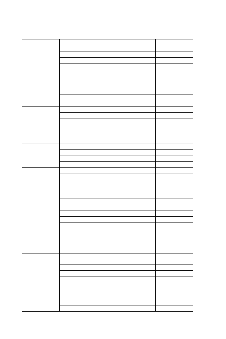
- 18 -
Match listan
HYDRAULISK STYRNING UPP TILL 150 HK
MOTOR
DRIVA
ÅR
Yamaha
60-702 slag
1990-2008
75C-902 Slaglängd
1998-2008
F70 4-taktare
2010-idag
115C-130B 2 Stroke
1990-2008
150F
1996-2007
150 HPDI VMAX 2-taktare
2000-2008
F75–F80 EFI 4-taktare
1999-2007
F100–F115–F150 EFI 4-taktare
1999-2007
F80-F100 4-taktare
2000-idag
F115–F150
2004-idag
Honda
BF80-BF90 4-taktare
1995-idag
BF115D
1998-2009
BF115A
2009-idag
BF130A
1998-2005
BF135-BF1504 Slaglängd
2005-idag
BF90-BF150V-TEC 4-taktare
2008-idag
Suzuki
DF70-80-904 Slaglängd
1998-idag
DF100-115-1404 Slaglängd
1998-2008
DF100-115-1404 Slaglängd ny modell
2008-idag
DF 1504 slag
2006-idag
Tohatsu
Nissan
70-902 slag
2004-idag
115-120-1402 Slaglängd
2004-idag
90-90-115TLD 4-taktare
2004-2011
Merkurius
Sjöman
75-90 2 Stroke
1990-2008
115-125-150 EFI 2-taktare
1990-2007
90-115-125 Optimax 2 Stroke
2004-idag
135-150 Optimax 2 Sträck okej
1999-idag
80-90 EFI 4-taktare
2000-idag
100-115 EFI 4-taktare
2007-idag
150 Fyrtaktare 4-taktare
2011-idag
Evinrude
E50-E55-E602 Slaglängd
2004-idag
E75-E902 Slaglängd
2004-idag
E115-E130-E1352 Slaglängd V4
1995-idag
1995-idag
E1502 Slaglängd V6
Selva
50-Madeira/Tjurhaj-60 Gråhaj / St.
Tropez-70 Mako Shark 2-taktare
1996-2008
80 Portofino Tigerhaj 2 Stroke
1995-2008
150 Vithaj 2 Stroke
2001-2007
50-60 Dorado EFI 4-taktare
2001-2007
100 EFI Marlin -115 EFINarwhal-150
EFI Späckhuggare 4-taktare
2000-idag
Johnson
BJ60-704 Slaglängd
2001-2007
BJ90-115-140 4-taktare
2001-2007
J90-115V4 2-taktare
1995-2007
Varning – För att minska risk för skada, användare måste läsa
instruktioner manualen noggrant.
Tillverkare: Shanghaimuxinmuyeyouxiangongsi
Adress: Shuangchenglu 803nong11hao1602A-1609shi,
baoshanqu, shanghai 200000 CN.
Importerad till Australien: SIHAO PTY LTD. 1 ROKEVA
STREETEASTWOODNSW 2122 Australien
Importerad till USA: Sanven Technology Ltd. Suite 250, 9166
AnaheimPlace, Rancho Cucamonga, CA 91730
REP
UK
YH CONSULTING LIMITED. C/O YH Consulting
Limited Office 147, Centurion House, London
Road, Staines-upon-Thames, Surrey, TW18 4AX
REP
EC
E-CrossStu GmbH
Mainzer Landstr.69,
60329 Frankfurt am Main.