
1
AS22684
Questions, problems, missing parts? Before returning to your retailer, call our
customer service department at 888-3KOBALT (888-356-2258), 8 a.m. - 8 p.m., EST,
Monday - Sunday. You could also contact us at [email protected].
MODEL #SC2502LW
ITEM #5202571
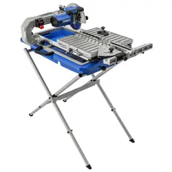
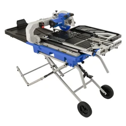
10-IN FOLDING WET TILE SAW
WITH STAND
Español p. 49
Serial Number MFG Date Purchase Date
ATTACH YOUR RECEIPT HERE
KOBALT and logo design are trademarks or
registered trademarks of LF, LLC. All Rights Reserved.

2
TABLE OF CONTENTS
PRODUCT SPECIFICATIONS
Product Specications.............................................................................................................. 2
Package Contents..................................................................................................................... 3
Know Your Tile Saw.................................................................................................................. 6
Important Safety Information..................................................................................................... 8
Electrical Safety Information..................................................................................................... 11
Preparation............................................................................................................................... 14
Assembly Instructions.................................................................................
......
........................ 15
Adjustment Instructions............................................................................................................. 32
Operating Instructions............................................................................................................... 35
Care And Maintenance.............................................................................................................. 42
Troubleshooting........................................................................................................................ 45
Replacement Parts List............................................................................................................ 46
Warranty.................................................................................................................................... 48
DESCRIPTION SPECIFICATIONS
Power Supply 120 V, 60 Hz
Motor 15 A
No Load Speed 4,000 RPM
Wheel 10 in.
x
5/8 in. (arbor)
Maximum Depth of Cut 3-3/4 in.
Rip Capacity (tile size) 40 in.
Diagonal Capacity (tile size) 24 in.
Bevel Angles 0°, 22.5°, 45°
3
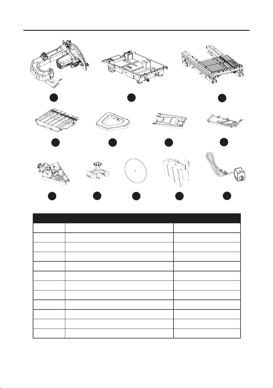
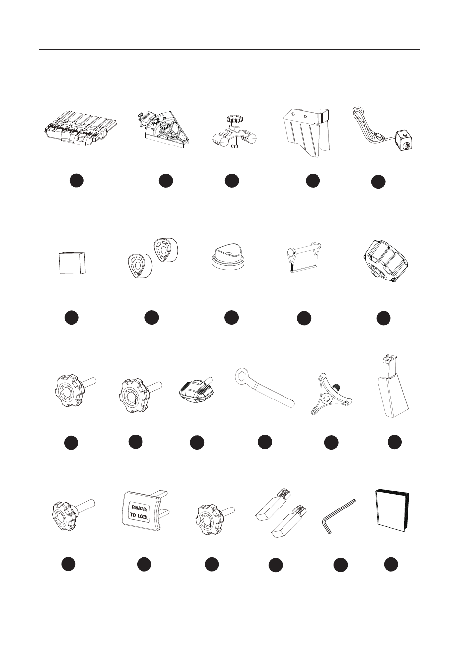
PACKAGE CONTENTS
PART DESCRIPTION QUANTITY
A Cutting head assembly 1
B Water tray 1
C Table frame 1
D Rear table extension 1
E Side table extension 1
F Rear water catch tray 1
G Side water catch tray 1
H Rip/Angle guide 1
I Tile clamp 1
J Cutting wheel 1
K Side splash guard 1
L Water pump 1
A
G
H
I
J K
L
C
D
B
FE
MAX
MIN
4
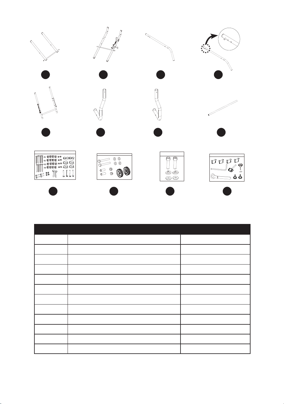
Q R S T
U V
OM N P
W
X
PART DESCRIPTION QUANTITY
M Center brace 1
N Inner leg assembly 1
O Left handle 1
P Right handle 1
Q Upper outer tube assembly 1
R Left lower outer tube 1
S Right lower outer tube 1
T Lower brace support 1
U Stand hardware bag 1
V Wheel hardware bag 1
W Cutting head assembly locking hardware bag 1
X Wheel wrench hardware bag 1
5
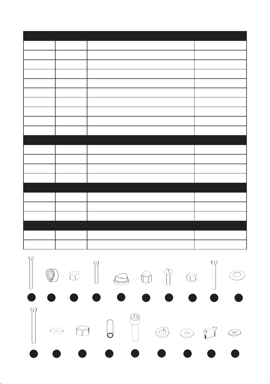
HARDWARE CONTENTS (not shown to actual size)
BAG PART DESCRIPTION QUANTITY
U aa M8*1.25-95 Bolt 8
bb Spacer 16
cc M8*1.25 T=8 Nut 8
dd M6*1.0-40 Bolt 4
ee Foot pad 4
M6*1.0 T=13 Crown nut 4
gg M5*0.8-40 Screw 4
hh M5*0.8 T=5 Nut 4
ii M8*1.25-45 Bolt 2
jj φ8.2*16-0.35 Spring washer 4
BAG PART DESCRIPTION QUANTITY
V kk M10*1.5-95 Hex head bolt 2
mm φ10*20-3 Washer 4
nn M10-1.5 T=10 Lock nut 2
oooo Sleeve 2
BAG PART DESCRIPTION QUANTITY
W pp M12*1.75-45 Bolt 2
qq φ12 Spring washer 2
rr φ12*21-2 Flat washer 2
BAG PART DESCRIPTION QUANTITY
X ss Hitch pin 4
tt 1/4*3/4-1/16 Flat washer 1
aa
bb cc
dd
ee
gg
hh ii jj
kk mm
nn oo
pp qq
rr ss
tt
6
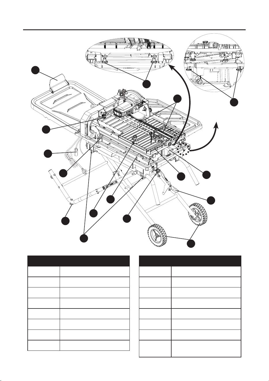
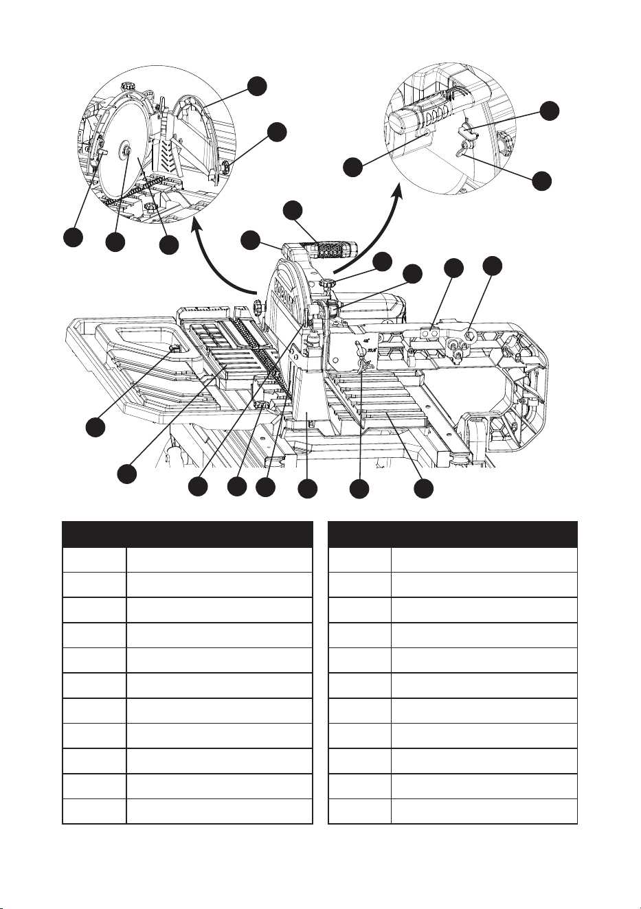
PART DESCRIPTION
ee Foot pads
ss Hitch pins
I Tile clamp
Y Table inserts
Z Filter
AA Sliding T-fence extension
BB Foot release lever
CC Wheels
PART DESCRIPTION
DD Drain plug
EE Frame locking lever
FF Arm folding lock knob
GG
Power cord receptacle
HH ON/OFF switch
II Small rear ap
JJ Water tray lock knobs
Ee
Sliding T-fence extension
lock knobs
KNOW YOUR TILE SAW
JJ
HH
EE
ee
II
AA
Z
BB
Y
CC
GG
I
FF
DD
FRONT OF SAW
ss
Ee
7
YY
ZZ
PART DESCRIPTION
D Rear table extension
J Cutting wheel
K Side splash guard
KK Motor handle
LL Cutting depth stop knob
MM Cutting head lock knob
NN Wheel wrench storage
OO Wheel wrench
PP Bevel lock knob
QQ Rear splash guard
RR Rear table extension lock knob
PART DESCRIPTION
SS Hold-down latch
TT Sliding table
UU Side table extension lock knob
VV LED light ON/OFF switch
WW Water nozzles
XX Arbor bolt
YY Wheel guard lock knob
ZZ Upper wheel guard
Aa Arbor lock button
Bb Water angle control
Cc Water volume control
LL
MM
OO
XX
PP
QQ
K
KK
SS
UU
NN
RR
WW
V V
J
Bb
Cc
Aa
D
TT

8
WARNING
To reduce risk of injury:
● Before any use, be sure everyone using this tool reads and understands all safety instructions
and other information contained in this manual.
● Save these instructions and review frequently prior to use and in instructing others.
● Keep guards in place and in working order.
● Remove adjusting keys and wrenches. Form habit of checking to see that keys and
adjusting wrenches are removed from tool before turning it on.
● Keep work area clean. Cluttered areas and benches invite accidents.
● Don't use in dangerous environment. Don’t use power tools in damp or wet locations,
or expose them to rain. Keep work area well lighted.
● Keep children away. All visitors should be kept safe distance from work area.
● Make workshop kid proof with padlocks, master switches, or by removing starter keys.
● Don't force tool. It will do the job better and safer at the rate for which it was designed.
● Use right tool. Don’t force tool or attachment to do a job for which it was not designed.
● Use proper extension cord. Make sure your extension cord is in good condition. When
using an extension cord, be sure to use one heavy enough to carry the current your product
will draw. An undersized cord will cause a drop in line voltage resulting in loss of power and
overheating. Minimum Gauge for Cord Sets shows the correct size to use depending on cord
length and nameplate ampere rating. If in doubt, use the next heavier gauge. The smaller the
gauge number, the heavier the cord.
● Wear proper apparel. Do not wear loose clothing, gloves, neckties, rings, bracelets, or other
jewelry which may get caught in moving parts. Nonslip footwear is recommended. Wear
protective hair covering to contain long hair.
● Always use safety glasses. Also use face or dust mask if cutting operation is dusty. Everyday
eyeglasses only have impact resistant lenses, they are NOT safety glasses.
● Secure work. Use clamps or a vise to hold work when practical. It’s safer than using your
hand and it frees both hands to operate tool.
● Don't overreach. Keep proper footing and balance at all times.
● Maintain tools with care. Keep tools sharp and clean for best and safest performance.
Follow instructions for lubricating and changing accessories.
● Disconnect tools before servicing; when changing accessories, such as wheels, bits, cutters,
and the like.
● Reduce the risk of unintentional starting. Make sure switch is in o position before
plugging in.
● Use recommended accessories. Consult the owner’s manual for recommended accessories.
The use of improper accessories may cause risk of injury to persons.
● Never stand on tool. Serious injury could occur if the tool is tipped or if the cutting tool is
unintentionally contacted.
● Check damaged parts. Before further use of the tool, a guard or other part that is damaged
should be carefully checked to determine that it will operate properly and perform its intended
function – check for alignment of moving parts, binding of moving parts, breakage of parts,
mounting, and any other conditions that may aect its operation. A guard or other part that is
damaged should be properly repaired or replaced.
● Direction of feed. Feed work into a wheel or cutter against the direction of rotation of the
wheel or cutter only.
● Never leave tool running unattended. Turn power o. Don’t leave tool until it comes to a
complete stop.
IMPORTANT SAFETY INFORMATION

9
SAFETY INSTRUCTIONS FOR TILE SAWS
CAUTION
● Wear appropriate hearing protection during use. Under some conditions and duration of use,
noise from this product may contribute to hearing loss.
● Do not connect unit to electrical power source until complete instructions are read and understood.
● Don't operate saw without the cutting wheel cover in place.
● Clean tile saw after each use for optimal operation.
● Use safety equipment. Always wear eye protection. Dust mask, non-skid safety shoes, hard
hat, or hearing protection must be used for appropriate conditions.
● Keep hands out of path of the cutting wheel. Never cut a piece where hand would be
3" (76 mm) or less from the cutting wheel.
● Do not perform any operation freehand, that is without holding the workpiece rmly against the
fence or edge guide.
● Never reach in back of the cutting wheel.
● Don't - Cut dry. If the cutting wheel is not cooled with water, serious damage will occur. Dry
cutting will increase exposure to harmful airborne dust.
● Turn o the tool and wait for the cutting wheel to stop before moving the workpiece or
changing settings.
● To reduce risk of injury, return the table to it's forward position after each cut.
● Do - Use rear and side table extensions to support large tile.
● Do - Make certain the cutting wheel rotates in the correct direction as indicated by the arrow
on the cutting wheel.
● Do - Be sure all clamp handles and knobs are tight before starting any operation.
● Do - Be sure all cutting wheel and clamp washers are clean and recessed sides of collars are
against the cutting wheel. Tighten arbor nut securely.
● Do - Keep the cutting wheel properly aligned.
● Do - Keep the motor air slots free of chips and dirt.
● Do – Always empty water from the reservoir and disconnect from the power source before
transporting. Water can splash into electrical components.
● Do - Keep hands out of the path of the cutting wheel.
● Do - Shut o power, disconnect cord from power source and wait for the cutting wheel to stop
before servicing, adjusting tool or changing cutting wheel.
● Don't - Attempt to operate on anything but designated voltage. Incorrect voltage may result in
shock, re, or unpredictable operation.
● Don't - Operate unless all knobs and clamps are tight.
● Don't - Use cutting wheels larger or smaller than those which are recommended.
● Don't - Force cutting action. Allow motor to reach full speed before cutting. Stalling or partial
stalling of motor can cause major damage.
● Don't - Use metal cutting abrasive wheels. The excessive heat and abrasive particles
generated by them will damage the saw.
● Do - Use continuous rim wheels only, no serrated edges or toothed cutting wheels.
● Don't - Allow anyone to stand behind saw.
● Don't - Place either hand in the cutting wheel area when the saw is connected to the power source.
● Don't - Use cutting wheels rated less than 4000 R.P.M.
● Don't - Place hands closer than 3" (76 mm) from the cutting wheel.
● Don't - Reach behind or underneath the saw unless it is turned o and unplugged.
● Don't - Move either hand from saw or workpiece until the cutting wheel has stopped.
● Secure work. Always place tile at on table and securely against fence.
● Never use a pan heater or other heat source for heating water. Damage to the tool, re or
personal injury could result.
● If the plug or receptacle does get wet, Don't unplug the cord. Disconnect the fuse or circuit
breaker that supplies power to the tool. Then unplug and examine for presence of water in the
receptacle.

10
PROPOSITION 65 WARNING
WARNING: Some dust created by power sanding, sawing, grinding, drilling, and other
construction activities contains chemicals known to the State of California to cause cancer, birth
defects or other reproductive harm. Some examples of these chemicals are:
● Lead from lead-based paints,
● Crystalline silica from bricks and cement and other masonry products, and
● Arsenic and chromium from chemically treated lumber.
Your risk from these exposures varies depending on how often you do this type of work. To reduce
your exposure to these chemicals: work in a well-ventilated area and work with approved safety
equipment, such as those dust masks that are specially designed to lter out microscopic particles.
Handling the power cord on this product may expose you to chemicals known to the state of
California to cause cancer and birth defects or other reproductive harm. Wash hands after handling.
For more information go to: www.P65Warnings.ca.gov
READ INSTRUCTION MANUAL: To reduce the risk of injury, user and all bystanders
must read instruction manual before using this product.

11
ELECTRICAL SAFETY INFORMATION
POWER SUPPLY AND MOTOR SPECIFICATIONS
WARNING: To avoid electrical hazards, re hazards, or damage to the tool, use proper circuit
protection. Use a separate electrical circuit for your tool. Your tile saw is wired at the factory
for 120 V operation. Connect to a 120 V, 15 Amp circuit and use a 15 Amp time delay fuse or
circuit breaker. To avoid shock or re, if power cord is worn, cut, or damaged in any way, have
it replaced immediately.
GROUNDING INSTRUCTIONS
WARNING: This tool must be grounded while in use to protect the operator from electrical shock.
IN THE EVENT OF A MALFUNCTION OR BREAKDOWN, grounding provides a path of least
resistance for electric currents and reduces the risk of electric shock. This tool is equipped with an
electrical cord that has an equipment-grounding conductor and a grounding plug. The plug must
be plugged into a matching receptacle that is properly installed and grounded in accordance with
all local codes and ordinances.
DO NOT MODIFY THE PLUG PROVIDED. If it will not t the receptacle, have the proper
receptacle installed by a qualied electrician.
IMPROPER CONNECTION of the equipment grounding conductor can result in risk of electric
shock. The conductor with the green insulation (with or without yellow stripes) is the equipment
grounding conductor. If repair or replacement of the electrical cord or plug is necessary, do not
connect the equipment grounding conductor to a live terminal.
CHECK with a qualied electrician or service person if you do not completely understand the
grounding instructions, or if you are not certain the tool is properly grounded.
USE only 3-wire extension cords that have three-pronged grounding plugs with three-pole
receptacles that accept the tool’s plug. Repair or replace damaged or worn cords immediately.
Use a separate electrical circuit for your tool. This circuit must not be less than #14 wire and
should be protected with a 15 Amp time delay fuse. Before connecting the motor to the power line,
make sure the switch is in the o position and the electric current is rated the same as the current
stamped on the motor nameplate. Running at a lower voltage will damage the motor.
GUIDELINES FOR EXTENSION CORDS
USE THE PR OPER EXTENSION CORD. Make sure your extension cord is in good condition.
Use an extension cord heavy enough to carry the current your product will draw. An undersized
cord will cause a drop in line voltage resulting in loss of power, overheating and burning out of the
motor. The table below shows the correct size to use depending on cord length and nameplate
ampere rating. If in doubt, use the next heavier gauge. The smaller the gauge number, the
heavier the cord.
Make sure your extension cord is properly wired and in good condition. Always replace a damaged
extension cord or have it repaired by a qualied technician before using it. Protect your extension
cords from sharp objects, excessive heat and damp or wet areas.
12
MINIMUM GAUGE FOR EXTENSION CORDS (AWG)
(When using 120 volts only)
Ampere Rating Total length of Cord
More Than Not More Than 25 ft. 50 ft. 100 ft. 150 ft.
0 6 18 16 16 14
6 10 18 16 14 12
10 12 16 16 14 12
12 16 14 12
Not Recommended
WARNING: Do not expose to rain or use in damp locations.
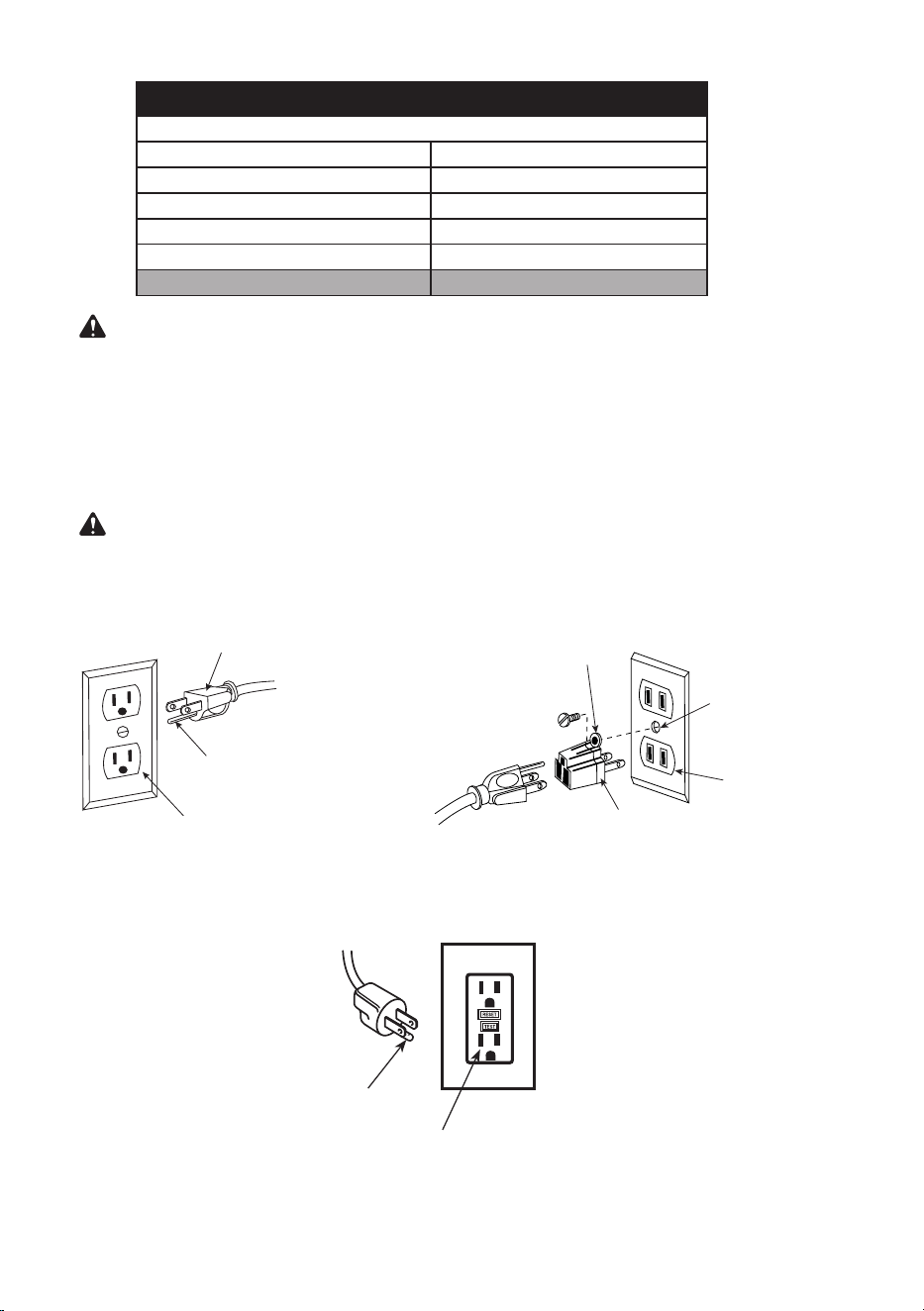
This tool is intended for use on a circuit that has a receptacle like the one illustrated in Fig. A.
Fig. A shows a three-pronged electrical plug and receptacle that has a grounding conductor. If
a properly grounded receptacle is not available, an adapter (Fig. B) can be used to temporarily
connect this plug to a two-contact grounded receptacle.
The adapter (Fig. B) has a rigid lug extending from it that MUST be connected to a permanent
earth ground, such as a properly grounded receptacle box.
CAUTION: In all cases, make certain the receptacle is properly grounded. If you are not sure,
have a qualied electrician check the receptacle.
Fig. B
Make sure this
is connected
to a known
ground.
Two-Pronged
Receptacle
Adapter
Grounding Lug
Fig. A
Three-Pronged Plug
Grounding Prong
Properly Grounded
Three-Pronged Receptacle
Fig. C
Grounding Prong
Grounding Fault Outlet
13
Fig. D
Drip
Loop
Power
cord
EXTENSION CORDS
1. Use only extension cords that are intended for outdoor use. These extension cords are
identied by a marking “Acceptable for use with outdoor appliances; store indoors while not in
use.” Use only extension cords having an electrical rating not less than the rating of the product.
Do not use damaged extension cords. Examine extension cord before using and replace if
damaged.
Do not abuse extension cords and do not yank on any cord to disconnect. Keep cord away
from heat and sharp edges.
Always disconnect the extension cord from the receptacle before disconnecting the product
from the extension cord.
2. WARNING: To reduce the risk of electrocution, keep all connections dry and o the
ground. Do not touch plug with wet hands.
3. Ground Fault Circuit Interrupter (GFCI) (not included) protection should be provided on the
circuit(s) or Fig. C outlet(s) to be used for the tile saw. Receptacles are available having
built-in GFCI protection and may be used for this measure of safety.
POSITION OF TILE SAW
To avoid the possibility of the appliance plug or
receptacle getting wet, position the tile saw to
one side of a wall-mounted receptacle to prevent
water from dripping onto the receptacle or plug.
The user should arrange a “drip loop” in the cord
connecting the saw to a receptacle (see Fig. D).
The “drip loop” is that part of the cord below
the level of the receptacle, or connector if an
extension cord is used, to prevent water traveling
along the cord and coming in contact with the
receptacle.
If the plug or receptacle does get wet, DO NOT
unplug the cord. Disconnect the fuse or circuit
breaker that supplies power to the tool. Then,
unplug and examine for presence of water in the
receptacle.

14
Before beginning assembly or operation of the product, make sure all parts are present. Compare
parts with package contents list and hardware contents list on pages 3 to 5. If any part is missing
or damaged, do not attempt to assemble, install or operate the product.
Estimated Assembly Time: 60 minutes.
Tools needed for assembly (included): Wheel Wrench, 10 mm Hex Wrench.
Tools required for assembly and adjustment (not included): Adjustable Wrench, 3 mm Hex Key,
13 mm Wrench, 17 mm Wrench, Framing Square, Combination Square, Phillips Screwdriver.
PREPARATION
15
ASSEMBLY INSTRUCTIONS
WARNING: To avoid injury, do not connect this tile saw to a power source until it is completely
assembled and you have read and understood the instruction manual.
ASSEMBLING THE STAND (FIG. 1, 2, 3, 4, 5, 6)
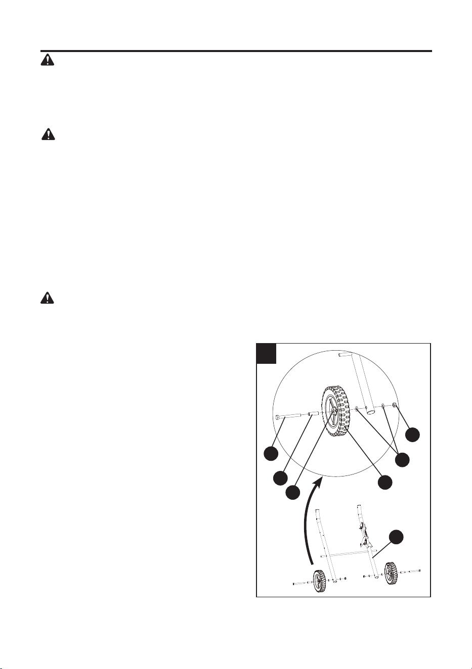
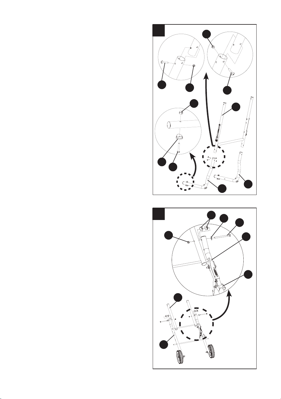
Assembling the wheels (Fig. 1) - BAG V
NOTE: Verify that the side of the wheel that has
more spokes is facing inward toward the stand.
● Place the inner leg assembly (N) on the
ground. Insert the sleeve (oo) into the
hole (1) of the wheel (CC). Attach one
wheel (CC) to one side of the inner leg
assembly (N) using a hex bolt (kk), two at
washers (mm) and a lock nut (nn), as shown.
● Tighten using the adjustable wrench (not
included) for the lock nut (nn) and the 17 mm
wrench (not included) for the hex bolt (kk).
NOTE: Do not overtighten, because doing so
will not allow the wheel to turn.
● Repeat the above steps for assembling the
other wheel to the other side of the inner leg
assembly (N).
1
mm
CC
N
nn
kk
oo
1
UNPACKING YOUR TILE SAW
Carefully unpack the tile saw and all its parts, and compare against the list and illustration on pages
3 to 5. With the help of an assistant, place the saw on a secure surface and examine it carefully.
● To avoid injury from unexpected starting or electrical shock, do not plug the power cord into a
source of power during unpacking and assembly. The cord must remain unplugged whenever
you are adjusting/assembling the tile saw.
● The tile saw is heavy and should be lifted with care. If needed, get the assistance of someone
to lift and move the tile saw.
● If any part is missing or damaged, do not attempt to assemble the tile saw, or plug in the
power cord until the missing or damaged part is correctly replaced.
● DO NOT use this product if any loose parts on the Package Contents or Hardware Contents
sections are already assembled to your product when you unpack it. Parts on this list are not
assembled to the product by the manufacturer and require customer installation. Use of a
product that may have been improperly assembled could result in serious injury.
If any parts are damaged or missing, please call 888-3Kobalt (888-356-2258) for assistance.
WARNING: Do not attempt to modify this tool or create accessories for use with this tool. Any
such alteration or modication is misuse and could result in a hazardous condition leading to
serious personal injury.
WARNING
16
2
gg
Q
R
S
hh
gg
hh
ee
dd
Assembling the left and right outer tubes
(Fig. 2) - BAG U
● Attach the left lower outer tube (R) to one
side of the upper outer tube assembly (Q)
using two screws (gg) and two lock nuts (hh),
as shown.
●
Tighten using the
adjustable
wrench (not
included) for the nuts (hh) and the Phillips
screwdriver (not included) for the screws (gg).
● Repeat the above steps to assemble the
right lower outer tube
.
Assembling the foot pads (Fig. 2) - BAG U
● Attach one foot pad (ee) to the left lower
outer tube (R) using one hex bolt (dd) and
one crown nut (), as shown.
● Tighten using the adjustable wrench (not
included) for the crown nut () and the 10 mm
wrench (not included) for the hex bolt (dd).
● Repeat the above steps to assemble the
other three foot pads
.
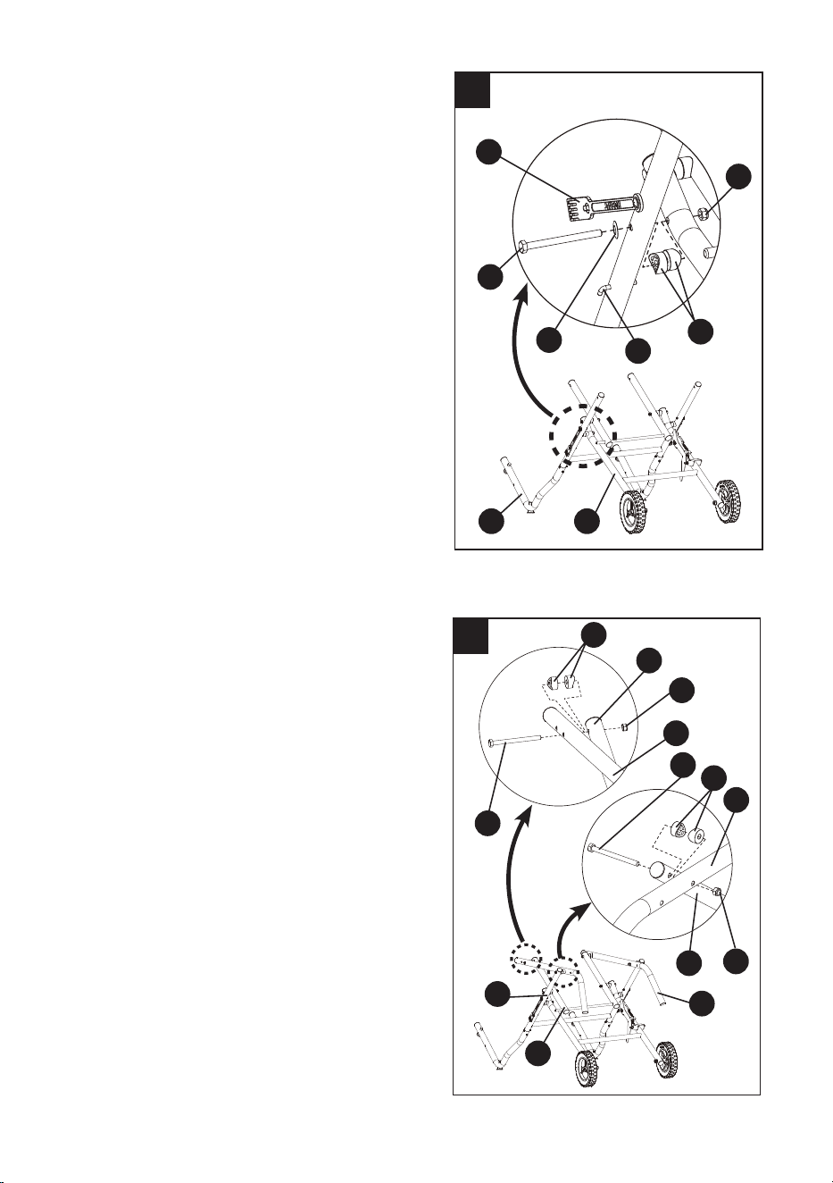
Assembling the center brace to the inner leg
assembly (Fig. 3) - BAG U
● Place the center brace (M) on top of the inner
leg assembly (N) (curve side up) with the
stop pin (1) under the foot release lever (BB).
NOTE: The stop pins rest on top of the inner
leg assembly.
● Attach the center brace (M) to the inner leg
assembly (N) using two hex bolts (aa), two
spring washers (jj), four small spacers (bb)
and two nuts (cc), as shown.
NOTE: The at sides of two spacers should
be placed against each other.
● Tighten with the adjustable wrench (not
included) for the nuts (cc) and the 13 mm
wrench (not included) for the hex bolts (aa).
NOTE: Do not overtighten, because doing so
will not allow the leg assembly to move.
3
aa
cc
M
1
BB
N
bb
jj
17
4
Assembling the left and right outer tubes to
the inner leg assembly (Fig. 4) - BAG U
● Pull the rubber strip (1) o the locking
hook (2). This will expose the center hole on
the outer tube.
● Position the inner leg assembly (N) and left
outer tube (3) so that they resemble an “X”.
● Attach the left outer tube (3) to the inner leg
assembly (N) using a hex bolt (aa), a spring
washer (jj), two small spacers (bb) and a
nut (cc), as shown.
● Tighten with the adjustable wrench (not
included) for the nut (cc) and the 13 mm
wrench (not included) for the hex bolt (aa).
NOTE: Do not overtighten, because doing so
will not allow the leg assembly to move.
● Repeat the above steps to assemble the
right outer tube to the inner leg assembly.
Assembling the left and right handles
(Fig. 5) - BAG U
NOTE: The handle with the tab should be
installed on the right.
● Attach the left handle (O) to the left outer
tube (1) and the center brace (M) using two
hex bolts (aa), four small spacers (bb) and
two nuts (cc), as shown.
● Tighten with the adjustable wrench (not
included) for the nut (cc) and the 13 mm
wrench (not included) for the hex bolt (aa).
NOTE: Do not overtighten, because doing so
will not allow the leg assembly to move.
● Repeat above steps for the right handle (P).
aa
jj
2
N3
cc
bb
1
5
aa
aa
O
O
M
1
cc
cc
1
M
bb
bb
P
18
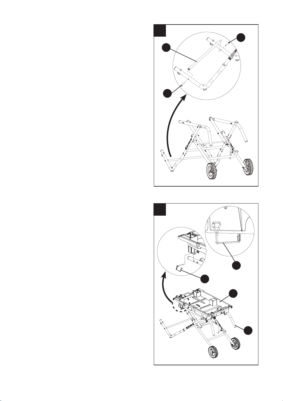
6
Assembling the lower brace support
(Fig. 6) - BAG U
● Attach the lower brace support (T) to the left
and right outer tubes using two hex bolts (ii),
as shown.
● Tighten the hex bolts (ii) with the adjustable
wrench (not included).
INSTALLING THE WATER TRAY TO STAND
(FIG. 7) - BAG X
● Place the water tray (B) on the stand. Align
the four holes in the water tray (B) with the
holes in the stand handles.
● Secure the water tray (B) to the stand using
four hitch pins (ss).
● Insert the pin from the outside and then
lock in place by inserting the end of the pin
into the hook on the hitch pin, as shown in
drawing.
ii
T
ii
7
ss
ss
B
P
FRONT
OF SAW
19
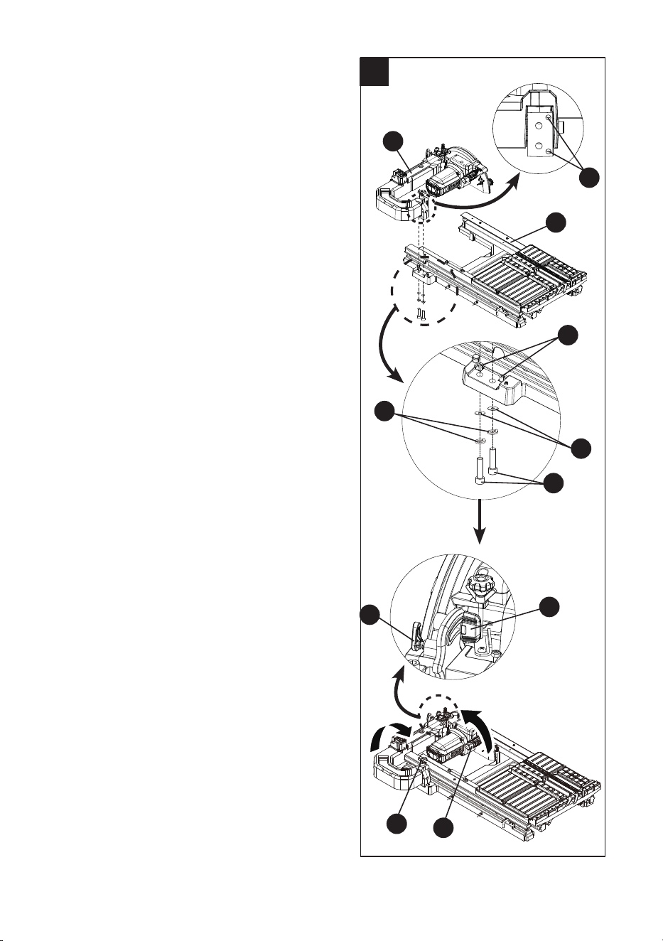
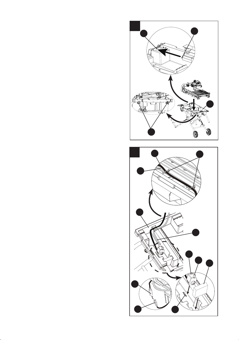
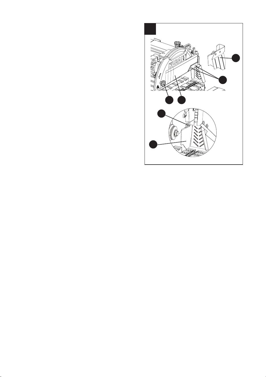
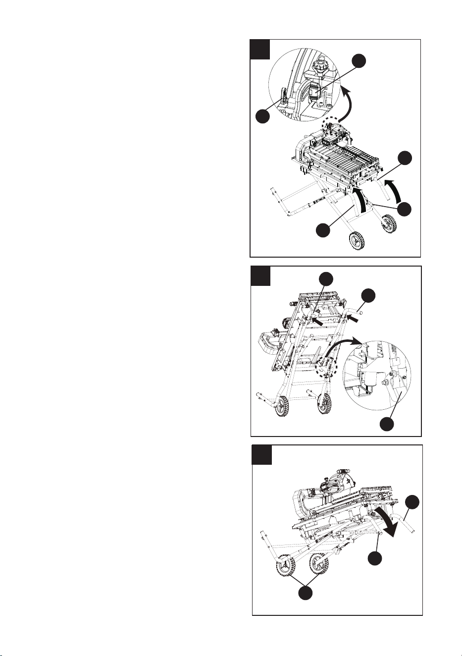
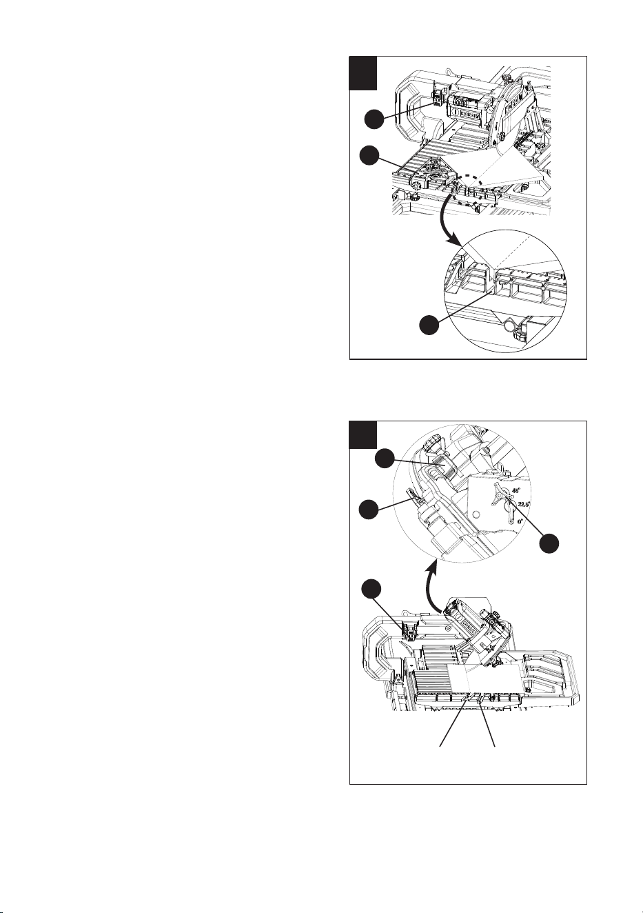
INSTALLING THE CUTTING HEAD ASSEMBLY
TO TABLE FRAME (FIG. 8) - BAG W
NOTE: The cutting head assembly and table frame
are heavy and it is recommended to be transported
with the help of 2 people, to safely move it.
● Place the table frame (C) and cutting head
assembly (A) on a at, secure surface.
● Align the holes in the cutting head
assembly (A) with the holes on the table
frame (C).
NOTE: Make sure that two location pins (1)
are fully engaged with two holes (2) in the
cutting head assembly (A).
● Thread two bolts (pp) through two spring
washers (qq) and two at washers (rr) into
the holes under the table frame and into the
cutting head assembly.
● Tighten the bolts using the provided 10 mm
hex wrench (Gg).
● On the cutting head assembly, pull out the
hold-down latch (SS) and grasp the motor
handle (KK) to raise up the cutting head.
● Release the hold-down latch (SS) to lock
into place and tighten the cutting head lock
knob (MM) to secure the cutting head.
NOTE: Make sure the cutting head locking
knob (MM
)
is fully engaged with the channel
before locking.
● Pull out the arm folding lock knob (FF) and
grasp the motor handle (KK) to raise the
cutting head assembly up. Push in the arm
folding lock knob (FF) and tighten it.
8
SS
MM
C
A
pp
qq
rr
1
Bottom view
2
FF
KK
20
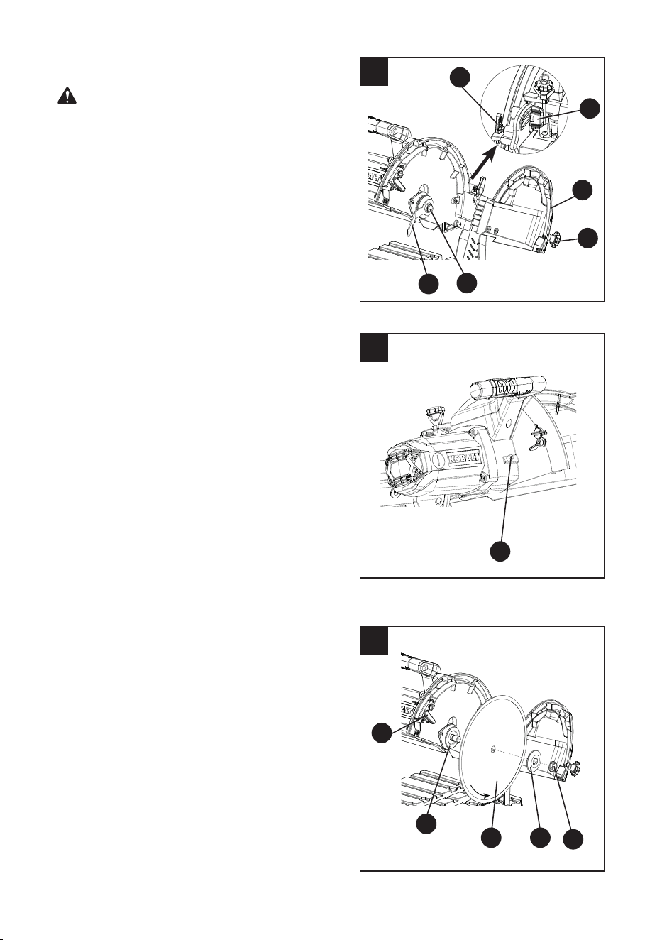
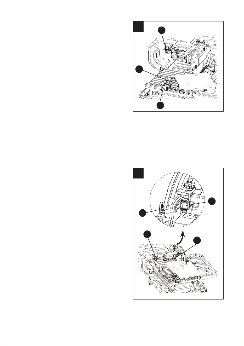
INSTALLING THE CUTTING HEAD ASSEMBLY
AND TABLE FRAME TO WATER TRAY (FIG. 9)
- BAG X
● Carefully lift the cutting head assembly
and table frame over the water tray (B), as
shown.
NOTE: The cutting head assembly and table
frame are heavy and it is recommended to
be transported with the help of 2 people, to
safely move it.
● Tilt the frame and insert heavy duty tabs (1)
into the slot (2) on water tray (B) at the back
of the unit.
● Secure the frame in place with two
water tray
lock
knobs (JJ) at the front of the unit.
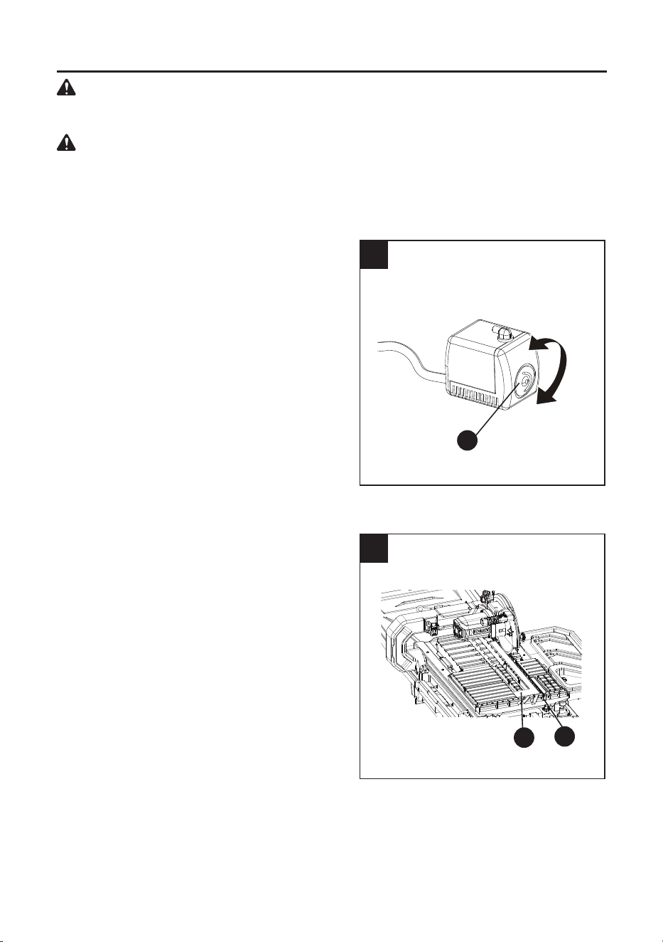
INSTALLING THE WATER PUMP (FIG. 10)
The water pump recirculates water from the
water tray to the cutting wheel.
● Place the lter (Z) in the water tray (B) as
shown.
● The water pump (L) is equipped with suction
feet to secure in place. Press down rmly
on the pump to attach the feet to the bottom
of the water tray (B), which is marked
"pump" (1).
● Connect the clear water tube (2) to the
barbed end of the 90° tting (3).
NOTE: Make sure the tube is placed under
the sliding table frame before installing onto
the pump tting.
● Secure the water pump power cord (4) and
clear water tube (2) by placing them into the
two cord clamps (5) on the left side of the
table frame and twisting the ends closed.
● Insert the water pump power cord plug (6)
into the power cord receptacle (GG) as
shown in Fig. 10. The water pump will start
when the tile saw is turned on.
NOTE: Do not use pump when not
submersed in water as it may damage the
pump. If the pump does not push water out
of the clear water tube onto the blade after
starting the saw, unplug the saw from the
electrical outlet, disconnect the clear water
tube from the pump. Submerse the pump in
water, reconnect the clear water tube to the
pump, plug the saw back into the electrical
outlet and start the saw to get the water
owing through the tube to the blade.
10
6
GG
4
5
9
2
1
JJ
B
B
2
2
1
L
3
Z
21
un
11
INSTALLING/REMOVING THE REAR TABLE
EXTENSION (FIG. 11) - BAG X
Move the sliding table to its most forward position
and lock in place.
To install the rear table extension:
●
Insert the tab (1) on the front of the rear
table extension (D) under the sliding table
and insert the slot (2) on the front of the
rear table extension (D) into the tab on the
sliding table
.
●
Insert the side tab (3) on the left side of the
rear table extension (D) into the slot (4).
● Align the hole (5) of the rear table
extension (D) with the hole (6) on sliding
table.
● Secure by
threading the rear table extension
lock knob (RR) through the washer (tt) into
the hole (6) located on right side of table.
NOTE: Make sure that the table insert on the
rear table extension is aligned with the table
insert on the sliding table.
To remove the rear table extension:
● Loosen the rear table extension lock
knob (RR) and then remove the knob and
the washer (tt).
● Pull the tab (3) out of the slot (4)
and pull
the tab (1) and slot (2) out of
the sliding
table, and
then remove the the rear table
extension (D).
3
4
2
1
D
6
5
tt
RR
Front
22
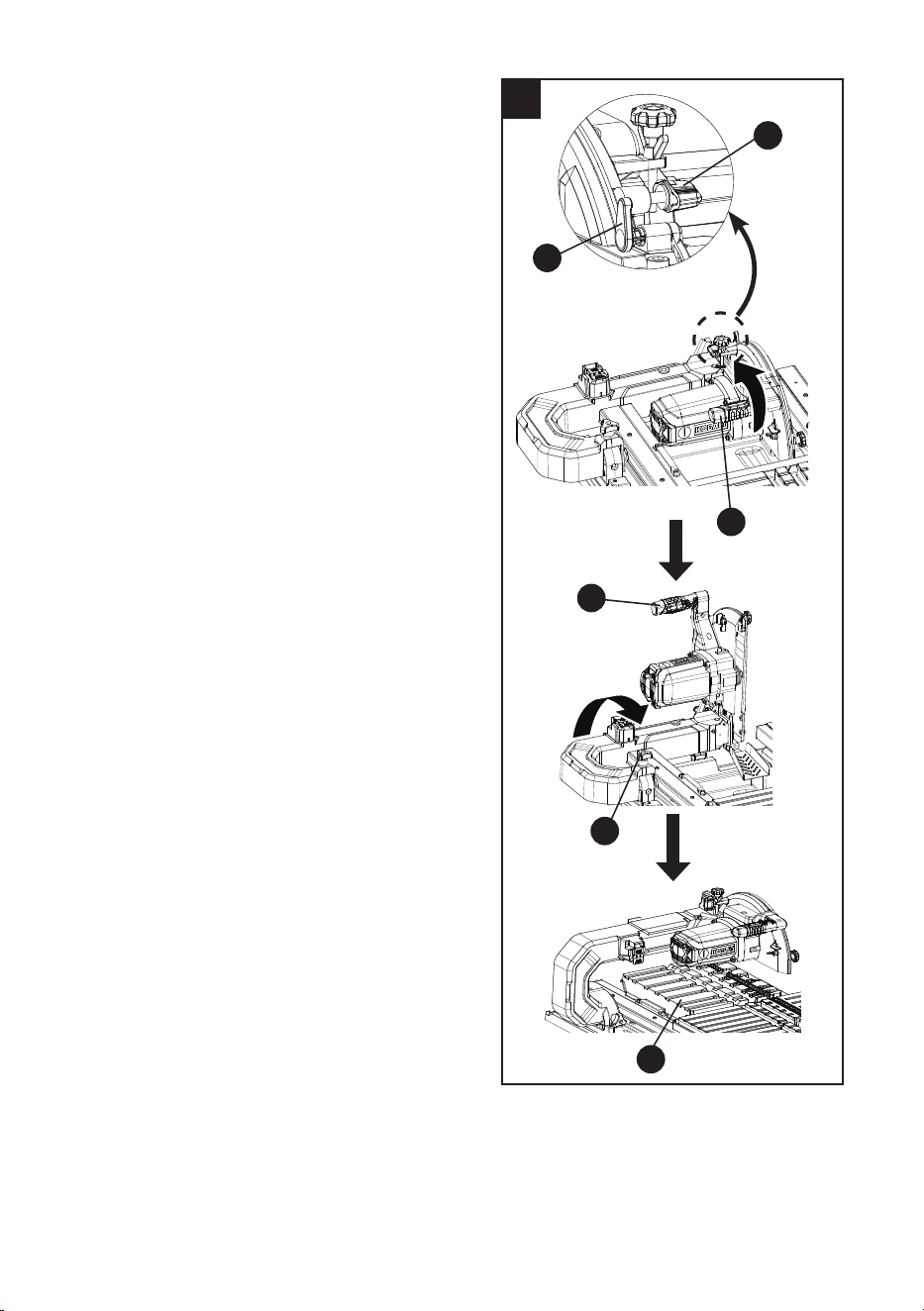
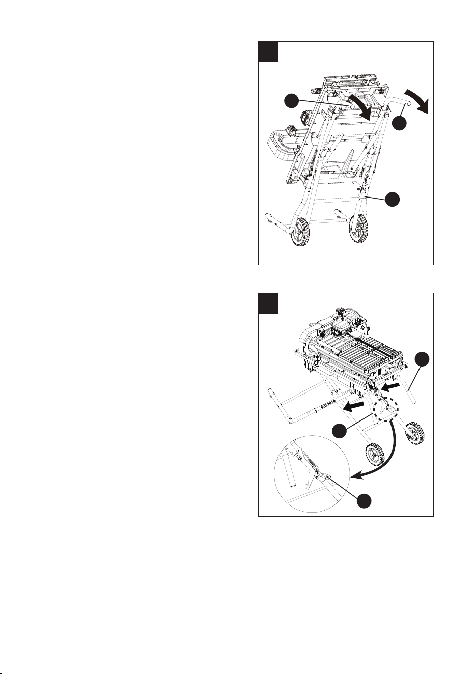
RAISING AND LOWERING THE CUTTING
HEAD ASSEMBLY (FIG. 12, 13)
Raising the cutting head assembly (Fig. 12)
● Pull out the hold-down latch (SS).
● Grasp the motor handle (KK) to raise up the
cutting head to a vertical position, and then
release the hold-down latch (SS). Tighten
the cutting head lock knob (MM).
● Pull out the arm folding lock knob (FF) and
hold the motor handle (KK) to raise up the
cutting head assembly. Push in the arm
folding lock knob (FF) and rotate clockwise
to tighten it.
● Install the rear table extension (D).
12
KK
FF
KK
D
SS
MM
23
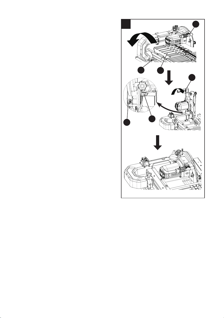
Lowering the cutting head assembly (Fig. 13)
● Remove the rear table extension (D).
● Loosen the arm folding lock knob (FF) and
pull it out.
● Grasp the motor handle (KK) to lower the
cutting head assembly backward.
● Release the arm folding lock knob (FF) and
it will lock into the hole automatically to lock
the arm.
● Loosen the cutting head lock knob (MM) and
pull out the hold-down latch (SS). Grasp the
motor handle (KK) to lower the cutting head
clockwise and then release the hold-down
latch (SS) to put it into the locking hole.
NOTE: When storing the saw, the cutting
head assembly should always be folded.
13
KK
MM
SS
FF
KK
D
24
14
INSTALLING THE SIDE SPLASH GUARD
(FIG. 14)
● Place the side splash guard (K) over the rear
guard.
● Insert the two holes on the outside of the side
splash guard over the two screws (1) located
on the side of the upper wheel guard (ZZ).
NOTE: It is not necessary to loosen or
remove the screws (1) on the wheel guard to
install the side splash guard.
● Loosen the wheel guard lock knob (YY) to
open the upper wheel guard (ZZ). Place the
hole on the inside of the side splash guard
and insert onto the screw (2).
2
K
K
1
YY ZZ
25
● Disconnect the saw from the power source.
● Move the sliding table to the front of the saw.
● Loosen the cutting head lock knob (MM) and
pull out the hold-down latch (SS) to raise the
cutting head to its upmost position. Release
the hold-down latch (SS) and tighten the
cutting head lock knob (MM). (Fig. 15)
● Loosen the wheel guard lock knob (YY) to
open the upper wheel guard (ZZ).
● Place the wheel wrench (OO) on the arbor
nut (XX).
● Press the arbor lock button (Aa), holding
it in rmly while turning the wheel wrench
counterclockwise to loosen. (Fig. 16)
● Remove the arbor nut (XX) and outer
ange (1). (Fig. 17)
NOTICE: Do not remove the inner ange (2).
● Place the 10 in. wheel (J) onto arbor. Make
sure that the wheel’s rotation arrow points in
the same direction as the rotation arrow on
the front of wheel guard.
NOTICE: The tile saw is equipped with two
water nozzles (WW) to wet the wheel during
operation. Make sure holes in nozzles face
the wheel and that wheel is positioned
between the two nozzles.
● Place outer ange (1) onto the arbor. The
ats on the outer ange align with the ats
on the arbor. Install with the cupped side of
the outer ange facing the tile saw wheel.
INSTALLING THE CUTTING WHEEL
(FIG.15, 16, 17)
WARNING
● DO NOT use cutting wheels rated less than
the no load speed of this tool. Failure to heed
this warning could result in personal injury.
DO NOT use a wheel with cracks, gaps, or
teeth.
● A 10 in. tile saw wheel is the maximum wheel
capacity of the saw. NEVER use a wheel
that is too thick. Larger wheels will come
in contact with the anti-splash guard, while
thicker wheels will prevent the wheel bolt
from securing the wheel on the arbor. Either
of these situations could result in serious
accidents and can cause serious personal
injury.
15
OO
XX
YY
ZZ
MM
SS
16
Aa
17
XX
1J
2
WW
Do not remove
inner ange
26
●
Place arbor nut (XX) on arbor. Press and hold the arbor lock button (Aa-Fig. 16) in. Using the
wheel wrench (OO) turning clockwise to tighten arbor nut (XX) securely. Release the arbor lock
button. (Fig. 15)
● Close the upper wheel guard (ZZ) and tighten the wheel guard lock knob (YY).
REMOVING THE CUTTING WHEEL (FIG. 15, 16, 17)
WARNING: To avoid injury from an accidental start, make sure the switch is in the OFF
position and the plug is not connected to the power source outlet.
● Disconnect the saw from the power source.
● Move the sliding table to the front of the saw.
● Loosen the cutting head lock knob (MM) and pull out the hold-down latch (SS) to raise the
cutting head to its upmost position. Release the hold-down latch (SS) and tighten the cutting
head lock knob (MM). (Fig. 15)
● Loosen the wheel guard lock knob (YY) to open the upper wheel guard (ZZ).
● Place the wheel wrench (OO) on the arbor nut (XX).
● Press the arbor lock button (Aa), holding it in rmly while turning the wheel wrench
counterclockwise to loosen. (Fig. 16)
● Remove the arbor nut (XX), outer ange (1) and cutting wheel (J). (Fig. 17)
NOTE: Do not remove the inner ange (2).
WHEEL WRENCH STORAGE (FIG. 18)
For convenient storage and prevention of loss,
there is a clip (NN) behind the arm (1) for storing
the wheel wrench (OO) when not in use.
18
NN
OO
1
27
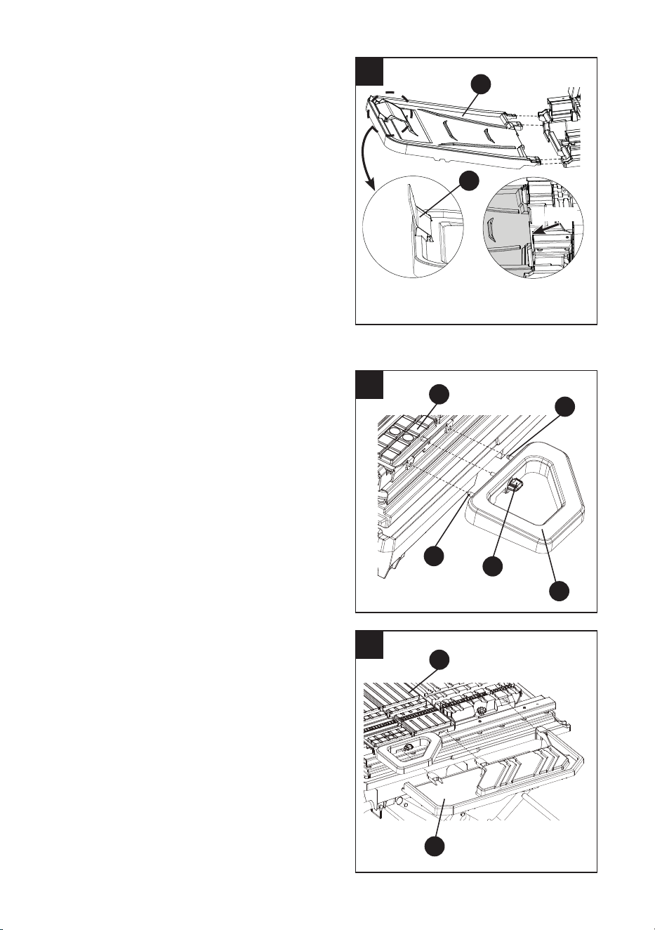
19
II
20
21
INSTALLING AND REMOVING THE REAR
WATER CATCH TRAY (FIG. 19)
Installing the rear water catch tray
● Align four slots located on the rear left and
right ends of the water pan with the arms of
the rear water catch tray (F).
● Tilt the rear water catch tray (F) up slightly
and then insert it into the slots of the water
pan as shown in Fig. 19.
NOTE: Make sure that the rear water catch
tray (F) is correctly installed before use as
shown in Fig. 19-1.
● The small rear ap (II) is installed and folded
over the rear water catch tray at the factory,
and should be unfolded when in use.
Removing the rear water catch tray
● Tilt the rear water catch tray (F) up slightly
and then pull it out of the slots of the water
pan.
INSTALLING THE SIDE TABLE EXTENSION
(FIG. 20) - BAG X
● From the right side of the saw, align the
pins (1) on the side table extension (E) with
the holes of the sliding table (TT).
● Secure in place by turning the side table
extension lock knob (UU) clockwise.
INSTALLING THE SIDE WATER CATCH TRAY
(FIG. 21)
● From the right side of the saw, slide the
side water catch tray (G) into the three slots
located on the sliding table (TT).
G
1
1
TT
E
UU
TT
Correct
Fig. 19-1
Flush
F
28
CLOSING/EXTENDING THE STAND
(FIG. 22, 23, 24, 25, 26)
● Remove water catch trays and any
workpieces from the tool.
● Lower the wheel and secure by locking the
cutting head in place using the cutting head
lock knob (MM) and hold-down latch (SS).
(Fig. 22)
To close the stand (Fig. 22, 23):
● Step on the foot release lever (BB) and grasp
left and right handles (O & P) simultaneously to
lift them up and away from the body. (Fig. 22)
● Push the saw until the foot release lever (BB)
clicks and locks into place. (Fig. 23)
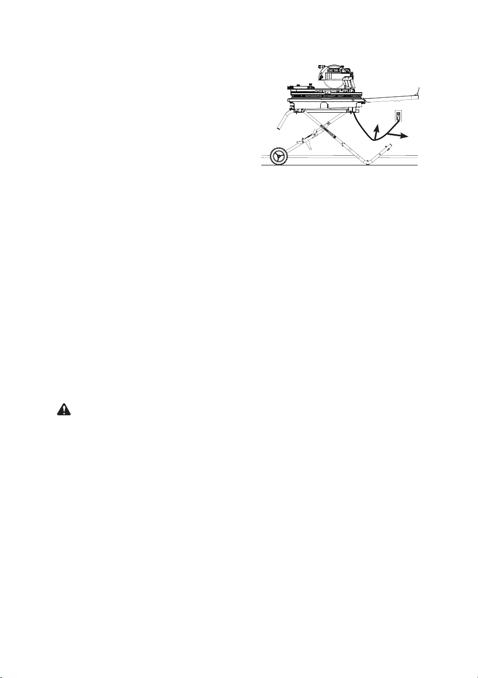
To move the stand (Fig. 24):
● Holding the left and right handles (O & P)
rmly, pull the handles toward you until
the stand and saw are balanced on the
wheels (CC).
● Push the saw to the desired location then
either open the stand for saw operation or
store the saw in a dry environment.
22
23
BB
MM
SS
BB
P
O
O
P
24
CC
O
P
29
To extend the stand (Fig. 25, 26):
● Step on the release lever (1) and pull the
left and right handles (O & P) toward you
simultaneously. (Fig. 25)
● Once the stand is released from the foot
release lever (BB), ease the stand toward the
oor by pushing the handles toward the oor.
● With your hands on the left and right
handles (O & P), push the stand towards
the ground until the saw is in an extended
position. (Fig. 26)
NOTE: The foot release lever will close over
the pin locking the stand in an extended
position.
25
BB
P
O
26
P
O
BB
30
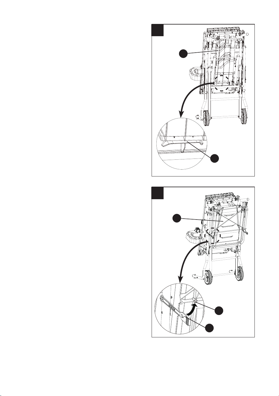
SIDE WATER CATCH TRAY STORAGE (FIG. 27)
When the stand is folded, the side water catch
tray (G) can be stored between the water tray
and center brace.
NOTE: The bottom of the side water catch tray
should be placed against the stop tab (1).
REAR WATER CATCH TRAY STORAGE (FIG. 28)
When the stand is folded, the rear water catch
tray (F) can be stored under the stand. Secure
by buckling the hole of the rubber strip (1) on the
screws (2) on both side of the rear water catch
tray.
27
G
1
28
F
1
2
31
INSTALLING THE RIP/ANGLE GUIDE (FIG. 29)
The Rip/Angle guide can be used from either the
left or right side of the tile saw wheel.
● Place the slot underside of the Rip/Angle
guide (H) on sliding T-fence extension (AA).
Lock the Rip/Angle guide (H) securely to
table by turning the lock knob (1) clockwise.
INSTALLING THE TILE CLAMP (FIG. 30)
NOTE: The tile clamp is designed to be used for
small or narrow pieces of tile. Use this clamp for
all cuts that cannot be held rmly by the miter/
angle guide and would require your hands to be
closer than 3” from the cutting wheel. The sliding
table has a channel for the tile clamp to be
located into position and tighten.
● For tile 3” and less in width: Insert the tile
clamp (I) into the T-shaped slot (1) from the
right side of the sliding table (TT).
NOTE: Make sure the clamp will not contact
the cutting wheel before starting the cut.
● For tile larger than 3” in width: Insert the tile
clamp (I) into the T-shaped slot (1) from the
left side of the sliding table (TT).
NOTE: Make sure the openings on the sliding
table for the 22.5 and 45 bevel angles do not
interfere with the tightening of the clamp.
29
1
AA
H
30
1
TT
I
Left Side of Table
Right Side of Table
1
TT I
Left
Side of
Saw
Right
Side of
Saw
Front of Saw
Slot for Tile Clamp
32
WARNING: This saw was adjusted for accuracy at the factory. During shipping the
components may have been moved out of alignment. In addition, usage and time will
necessitate adjustments to be made.
WARNING
To prevent personal injury:
● Always disconnect plug from the power source when making any adjustments.
● This adjustment must be correct or accurate cuts can not be made. Also inaccurate adjustment
can result serious personal injury.
32
1
2
ADJUSTMENT INSTRUCTIONS
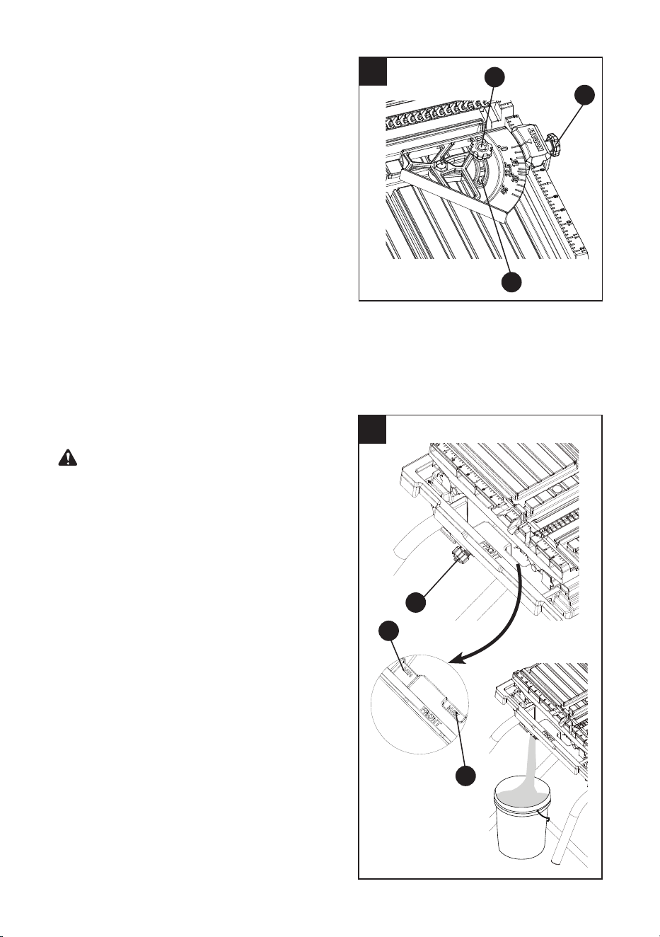
ADJUSTING THE FLOW OF WATER ON THE
PUMP (FIG. 31)
● Fill the water pan with clean water as
described below.
● Locate the “Max/Min” water ow selector (1)
on the pump. For best performance, set the
ow to “Max” to control the ow of water over
the wheel.
● The pump turns on when the motor is
turned on. Let the cutting wheel build up to
full speed and wait for the wheel to get wet
before moving the tile into the wheel.
NOTE: The ow of water can also be adjusted
using the external water volume control. See
page 37 for instructions.
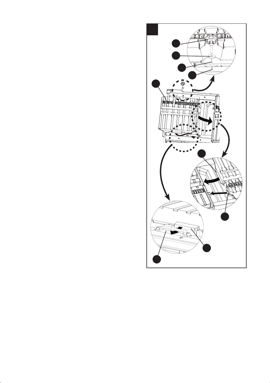
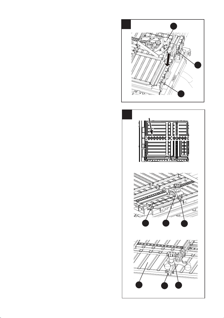
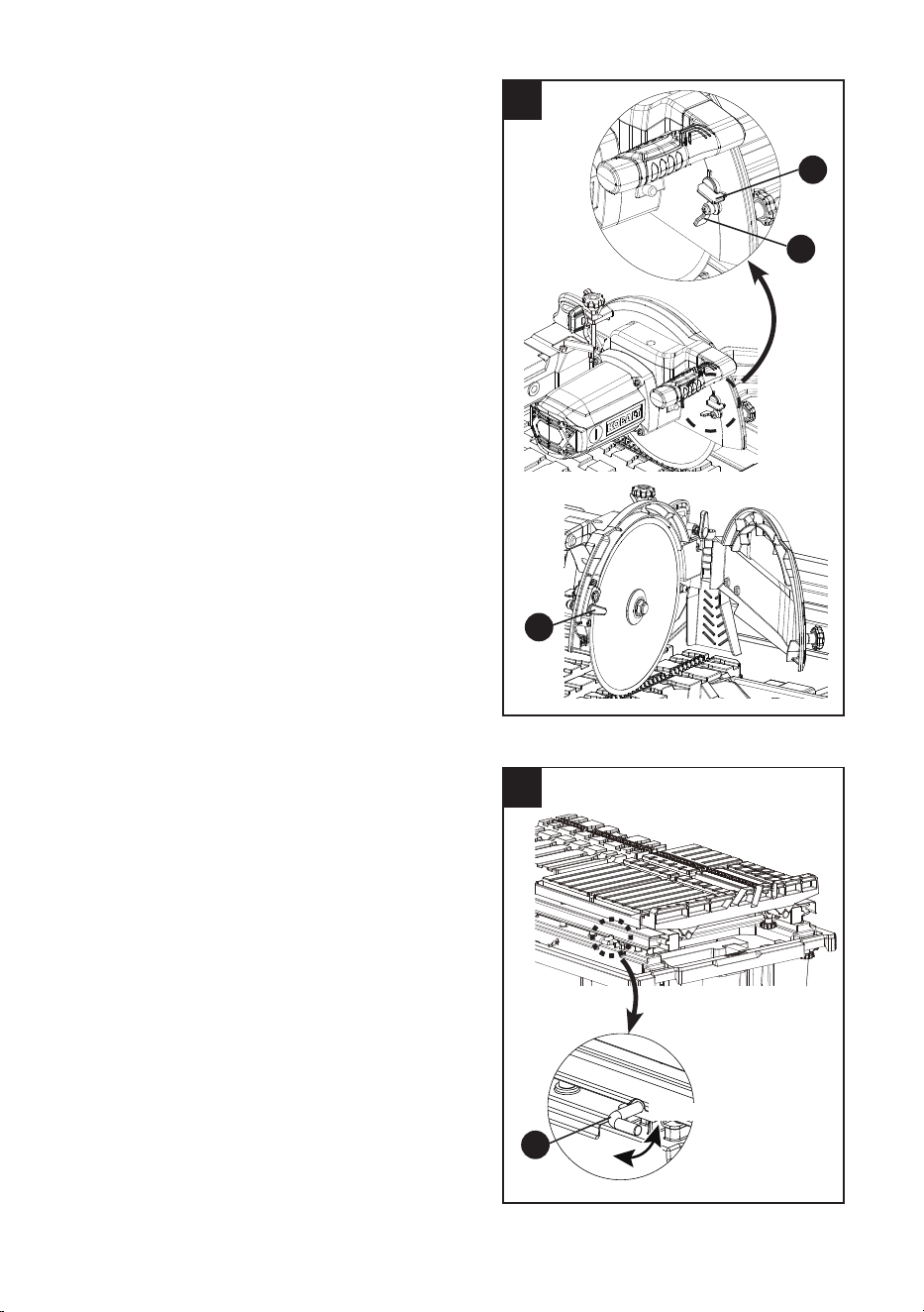
SQUARING THE CUTTING WHEEL
(FIG. 32, 33, 34)
Checking the cutting wheel alignment (Fig. 32)
● Place a 90° framing square (1) at on the
sliding table surface with one end against the
sliding T-fence extension.
● Push the sliding table along the cutting
wheel to determine if the groove along the
90° framing square is consistently ush
against the wheel throughout the length of
the stroke.
● If the groove is not consistent, see the next
steps.
31
1
MAX
MIN
Max
Min
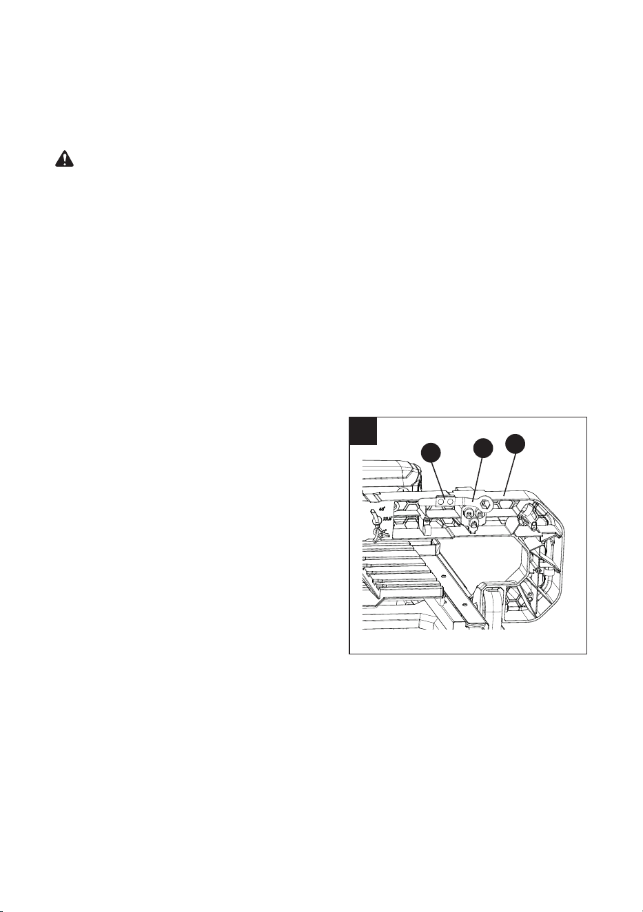
33
33
PP
4
BOTTOM VIEW
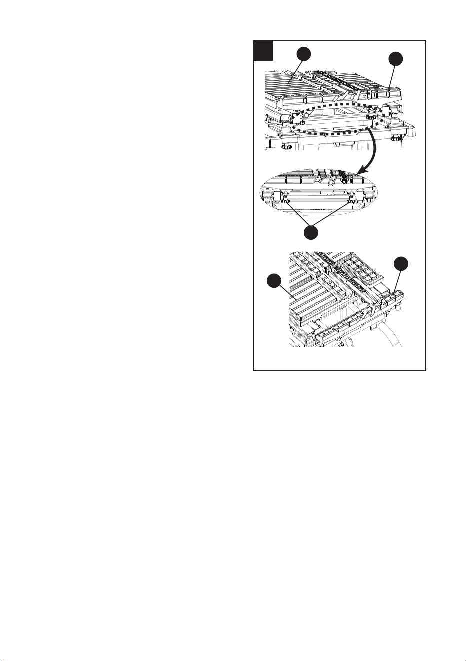
34
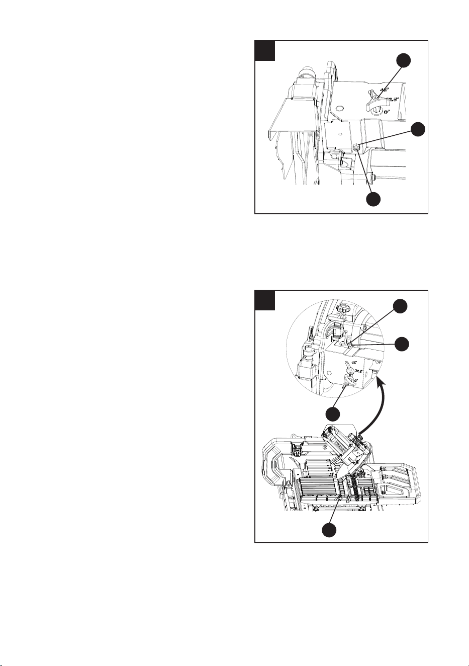
Adjusting the cutting wheel 90° to sliding
table (Fig. 32, 33)
● Disconnect the saw from the power source.
● Loosen the bevel lock knob (PP) and make
sure the cutting wheel is in the maximum
vertical position. Tighten the bevel lock
knob (PP).
● Place a 90° framing square on the sliding
table surface.
● If the cutting wheel is not 90° to the
groove (2-Fig. 32), loosen the lock
nut (3) with a adjustable wrench and turn
the hex bolt (4) (located under the cutting
arm assembly as shown in Fig. 33) in or
out accordingly with a 3 mm hex key until
the wheel is ush with the framing square
while moving down the center of the groove.
Tighten the lock nut (3).
● Make sure that the cutting wheel does not
touch either side of the groove (2-Fig. 32) in
the sliding table by pushing the table past
the cutting wheel.
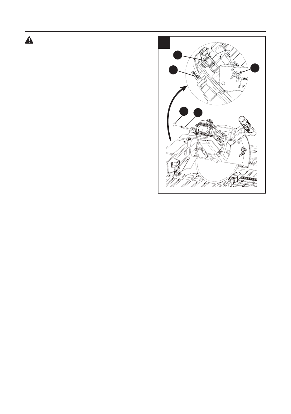
Adjusting the cutting wheel 45° to sliding
table (Fig. 34)
● Disconnect the saw from the power source.
● Loosen the bevel lock knob (PP) and move
the cutting wheel to the maximum bevel
position.
● Place the combination square to the sliding
table surface.
● If the cutting wheel is not 45° to the
groove (5), loosen the lock nut (6)
with a adjustable wrench and turn the
45° hex bolt (7) (located on top of the
cutting arm assembly as shown in
Fig. 34) in or out accordingly by using a
3 mm hex key until it is 45° to the sliding
table surface and tighten the bevel lock
knob (PP). Tighten the lock nut (6).
● Make sure that the cutting wheel does not
touch either side of the groove (5) in the
sliding table by pushing the table past the
cutting wheel.
7
6
PP
5
3
34
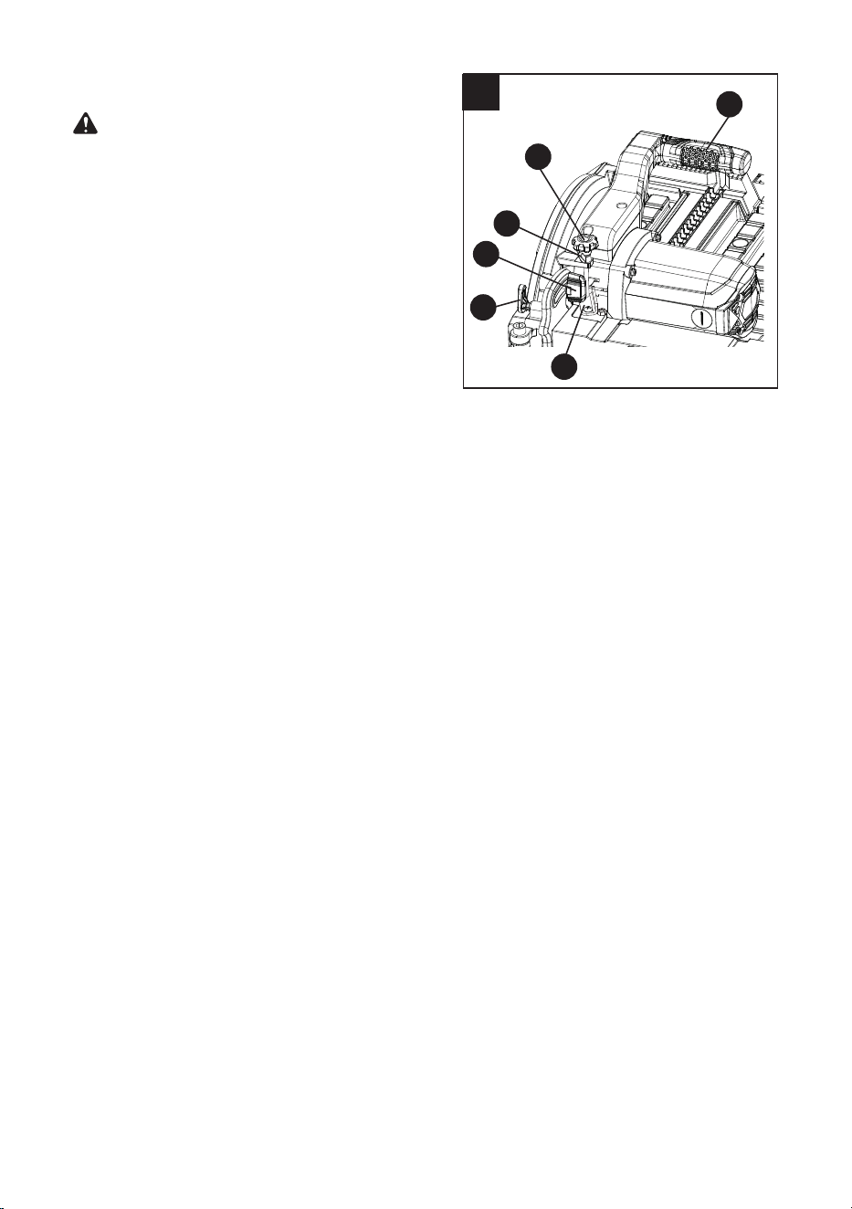
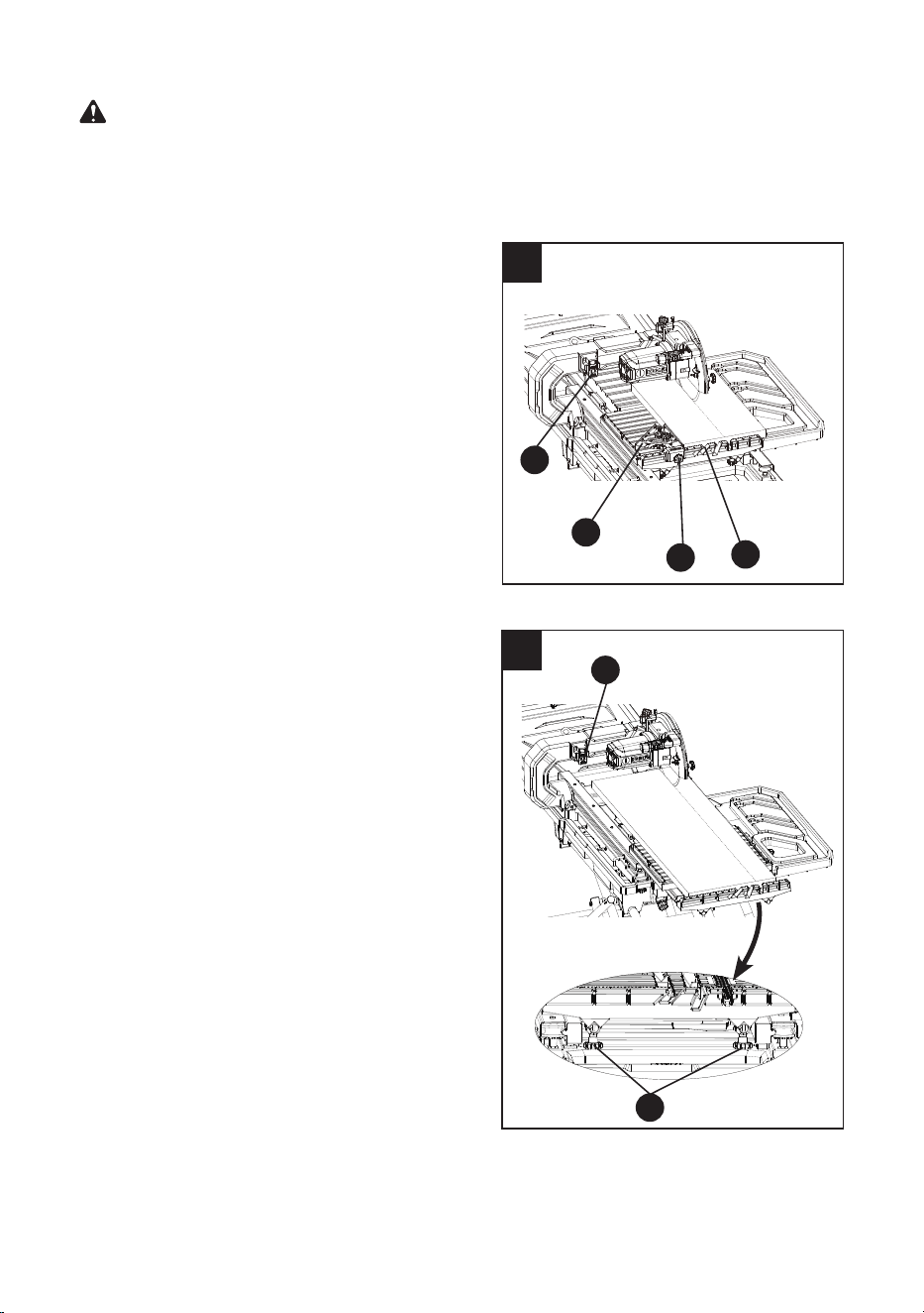
CUTTING WHEEL DEPTH ADJUSTMENT
(FIG. 35)
WARNING: Improperly adjusting the cutting
wheel depth could cause the cutting wheel
to come in contact with the sliding table
resulting in damage to the unit and/or
possible serious injury.
The depth stop is factory set to provide
maximum cutting capacity for the wheel provided
with the saw. Make adjustments if desired.
Adjusting the cutting depth
The depth of cut can be preset for even and
repetitive shallow cuts.
● Disconnect the saw from the power source.
● To adjust the depth, loosen the cutting head
lock knob (MM) and pull out the hold-down
latch (SS). Grasp the motor handle (KK) to
adjust the cutting head down until the cutting
wheel is at the desired depth.
● While holding the cutting head in the desired
position, loosen the wing nut (1) and turn the
cutting depth stop knob (LL) until it touches
the stop plate (2). Tighten the wing nut (1)
and then release the hold-down latch (SS)
and tighten the cutting head lock knob (MM).
● Recheck the cutting wheel depth by pushing
the sliding table front to back past the cutting
wheel and make sure the cutting wheel does
not touch the grooves of the sliding table.
Maximum cutting depth
The maximum depth travel of the cutting head
was set at the factory.
● Disconnect the saw from the power source.
● Loosen the cutting head lock knob (MM) and
pull out the hold-down latch (SS). Grasp the
motor handle (KK) to adjust the cutting head
to a 0° angle. Make sure the wheel sits in the
groove in the sliding table.
NOTICE: Do not lock the cutting head lock
knob while making this adjustment.
● After adjustment is complete, tigthen the
cutting head lock knob (MM).
● Recheck the cutting wheel depth by pushing
the sliding table front to back.
35
KK
LL
1
MM
SS
2
35
BEFORE USING THE TILE SAW
WARNING: To avoid mistakes that could cause serious, permanent injury, do not plug the tool
in until the following steps are completed:
● Completely assemble and adjust the tile saw, following the instructions (SEE ASSEMBLY AND
ADJUSTMENTS SECTIONS).
● Review the entire manual and understand all safety instructions and operating procedures in
this Instruction Manual (SEE IMPORTANT SAFETY & OPERATIONS SECTIONS).
● To avoid injury or possible death from electrical shock, make sure your ngers do not touch
the plug’s metal prongs when plugging or unplugging your tile saw (SEE ELECTRICAL
REQUIREMENTS AND IMPORTANT SAFETY SECTIONS).
BASIC SAW OPERATIONS
● Overlling the water tray can lead to water entering the motor compartment and potential
electric shock.
● When lling/draining water tray, make sure wet tile saw is unplugged from wall outlet.
OPERATING INSTRUCTIONS
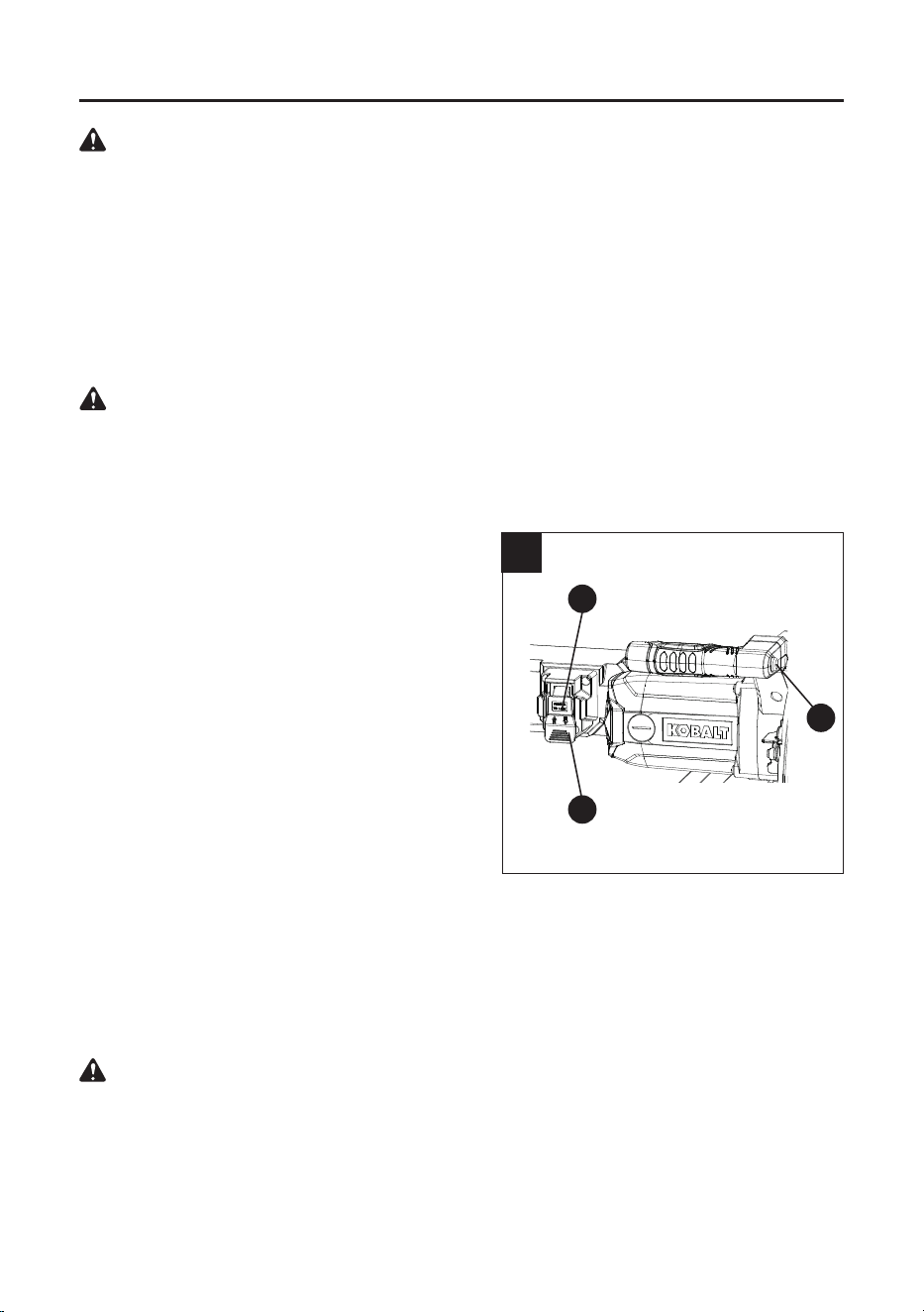
LED LIGHT ON/OFF SWITCH (FIG. 36)
Turn the LED light on and o by pressing the
LED light ON/OFF switch (VV) located on the
side of the motor handle.
NOTE: The saw must be plugged in for the LED
light to operate.
ON/OFF SWITCH (FIG. 36)
The ON/OFF switch has a removable safety
key (Dd). With the key removed from the switch,
unauthorized and hazardous use by children and
others is minimized and the saw will not turn on.
● To turn the saw “ON”, insert the safety
key (Dd) into the slot of the ON/OFF
switch (HH), and move the switch upward to
the “ON” position.
● To turn the saw “OFF”, move the ON/OFF
switch (HH) downward.
● To lock the switch in the OFF position, grasp
the sides of the safety key (Dd), and pull it
out.
● With the switch key removed, the switch will
not operate to power the saw on.
WARNING: ALWAYS lock the switch “OFF”
when the tile saw is not in use. Remove the
key and keep it in a safe place. In the event
of a power failure, blown fuse, or tripped
circuit breaker, turn the switch “OFF” and
remove the key, preventing an accidental
startup when power comes on.
WARNING
36
Dd
VV
HH
36
37
USING THE RIP/ANGLE GUIDE (FIG. 37)
This guide can be placed on either side of the
cutting wheel.
● Loosen the lock knob (1) to move the guide
along the front rail to the desired position and
tighten the lock knob (1).
● Loosen the Rip/Angle guide adjust lock
knob (2) to turn the guide to the desired
angle along the arc slot (3) and then tighten
the Rip/Angle guide adjust lock knob (2).
NOTE: Please make sure the cutting wheel
will not make contact with this guide during the
cutting operation.
2
3
1
FILLING/CHANGING THE WATER RESERVOIR
(FIG. 38)
WARNING:
When lling/draining water tray,
make sure wet tile saw is unplugged from
wall outlet.
To ll the reservoir with water
● Make sure the drain plug (DD) on the water
tray is tight.
● Fill the water tray (B) with clean water.
Ensure the water level is between "MAX" (1)
and "MIN" (2) ll lines. Do not overll.
To change the reservoir water
● Disconnect the saw from the power source.
● Place a bucket under the drain plug (DD).
● Remove the drain plug (DD) and empty
waste water into a bucket. Do not allow the
water to splash onto the ground or around
the saw.
● Rinse the water reservoir thoroughly.
● Discard the waste water in accordance with
local regulations.
● Replace the drain plug (DD) and rell water
tray with clean water.
38
DD
2
1
37
EXTERNAL WATER CONTROLS (FIG. 39)
Water nozzles are adjustable to provide
maximum water for cutting and change water
spray direction.
● The water volume control (Cc) allows easy
adjustment of nozzles (WW) to provide water
volume. To provide maximum water volume,
turn the water volume control (Cc) clockwise.
To provide minimum water volume, turn the
water volume control (Cc) counterclockwise.
● The water angle control (Bb) allows easy
adjustment of nozzles (WW) to desired angle.
LOCKING AND UNLOCKING THE SLIDING
TABLE (FIG. 40)
To unlock the sliding table
● Pull the frame locking lever (EE) out and
turn 90˚ counterclockwise to the “unlocked
position” to unlock the sliding table
.
To lock the sliding table
● Pull the frame locking lever (EE) out and turn
90˚ clockwise to the “locked position”.
● Release the lever.
NOTE: When you push the sliding table, it
will “click” into place. This is the frame locking
lever snapping into a hole in the sliding table
locking it in place.
39
Cc
WW
Bb
un
40
EE
unlock
lock
38
un
41
LOCKING AND UNLOCKING THE SLIDING
T-FENCE EXTENSION (FIG. 41)
● Lock the sliding table (TT).
● Loosen the two sliding T-fence extension
lock knobs (Ee) to unlock the sliding T-fence
extension (AA).
● To lock the sliding fence (AA), tighten two
sliding T-fence lock knobs (Ee).
Ee
AA
AA
TT
TT
Fold
Extend
39
42
STRAIGHT CUT (FIG. 42)
● Fill the water tray with clean water.
● Using a pencil or marker mark the area to be
cut on tile.
● Loosen the lock knob (1) and move the Rip/
Angle guide (H) to the desired position.
Tighen the lock knob (1).
● Place the tile on the sliding table and rmly
against the Rip/Angle guide (H) and sliding
T-fence extension (AA).
● Pull the ON/OFF switch (HH) upward to turn
on the tile saw. Allow the cutting wheel to
reach full speed and wait until the stream
of water from the water nozzle completely
covers the cutting wheel.
● Using both hands to slowly push the sliding
table assembly toward the cutting wheel to
feed the tile into the cutting wheel (Never
force the material through the wheel. Move at
a slow consistent pace.).
● Turn the tile saw o once cut is performed.
CUTTING LONG TILE (UP TO 40”) (FIG. 43)
● Move the sliding table to the front of the saw.
● Loosen the two sliding T-fence extension
lock knobs (Ee) and pull the sliding T-fence
extension to the front position.
NOTE: Do not lock the sliding T-fence
extension lock knobs.
● Using a pencil or marker mark the area to be
cut on tile.
● Place up to 40” tile on the sliding table and
against the sliding T-fence extension.
● Pull the ON/OFF switch (HH) upward to turn
on the tile saw. Allow the cutting wheel to
reach full speed and wait until the stream
of water from the water nozzle completely
covers the cutting wheel.
● Using both hands to slowly push the sliding
table toward the cutting wheel. As the cutting
proceeds, simultaneously push the sliding
T-fence extension forward to feed the tile into
CUTTING OPERATION
WARNING: Before making any adjustments or removing or installing attachments or
accessories, make sure the switch is in the OFF position to avoid injury from an accidental start.
Before turning the tile saw on, verify the alignment of the sliding table and the cutting wheel.
Always center the cutting wheel in one of the sliding table grooves before cutting. Make sure the
cutting wheel does not contact the tile or table before turning saw on.
1
AA
H
HH
43
Ee
HH
the cutting wheel (Never force the material through the wheel. Move at a slow consistent pace).
● Turn the tile saw o once cut is performed.
NOTE: For cutting small/narrow tile, see the section of “INSTALLING THE TILE CLAMP” on page 31.
40
44
45
DIAGONAL CUT (FIG. 44)
NOTE: Diagonal cuts are also referred to as
“long point to point cuts.”
● Fill the water tray with clean water.
● Using a pencil or marker mark the area to be
cut on tile.
● Align one point of the tile against the cut
indicator (1) of the sliding table. The cut
indicator means the exact location where the
cutting wheel will pass through the sliding
table.
● Align the front of the tile to the cutting wheel
and hold against the Rip/Angle guide (H),
which should be adjusted to proper angle.
● Pull the ON/OFF switch (HH) upward to turn
the tile saw on to allow the cutting wheel at
the full speed and wait until the stream of
water from the water nozzle completely cover
the cutting wheel.
● Using both hands to slowly push the sliding
table toward the cutting wheel to feed the tile
into the cutting wheel.
● Turn the tile saw o once cut is performed.
BEVEL CUT (FIG. 45)
NOTE: Bevel cuts can be made at 22.5 and 45
angles.
● Fill the water tray with clean water.
● Using a pencil or marker marks the area to
be cut on tile.
● Loosen the cutting head lock knob (MM) and
pull out the hold-down latch (SS) to raise the
cutting head up. And then tighten the cutting
head lock knob (MM).
● Loosen the bevel lock knob (PP) to tilt the
cutting head to 22.5° or 45° clockwise.
Tighten the bevel lock knob (PP).
● Loosen the cutting head lock knob (MM) to
lower the cutting head in one of the two miter
slots in the table. Tighten the cutting head
lock knob (MM).
NOTICE: Check to insure the cutting wheel
does not contact the table before turning the
saw on.
● Pull the ON/OFF switch (HH) upward to turn
the tile saw on to allow the cutting wheel at
the full speed and wait until the stream of
water from the water nozzle completely cover
the cutting wheel.
● Using both hands to slowly push the sliding
table toward the cutting wheel to feed the tile
into the cutting wheel.
● Turn the tile saw o once cut is performed.
MM
PP
SS
HH
For 45°
bevel cut
For 22.5°
bevel cut
1
H
HH
41
46
1
HH
2
MITER CUT (FIG. 46)
NOTE: Miter cuts are used for cutting outside
and inside corners on material, decorative chair
rail and base moulding with the material at any
angle to the cutting wheel other than 90°.
● Fill the water tray with clean water.
● Using a pencil or marker, mark the area to
be cut on tile.
● Loosen the lock knob (1) to move the Rip/
Angle guide along the front rail to the desired
position and then tighten the lock knob (1).
● Loosen the Rip/Angle guide adjust lock
knob (2) to turn the guide to the desired
angle along the arc slot and then tighten the
Rip/Angle guide adjust lock knob (2).
● Pull the ON/OFF switch (HH) upward to turn
the tile saw on to allow the cutting wheel
at the full speed and wait until the stream
of water from the water nozzle completely
cover the cutting wheel.
● Using both hands to slowly push the sliding
table toward the cutting wheel to feed the tile
into the cutting wheel.
● Turn the tile saw o once cut is performed.
PLUNGE CUT (FIG. 47)
NOTE: Plunge cuts mean to position the tile
under the cutting wheel directly and lower the
cutting head to make cuts onto the interior of the
tile, such as electrical outlets or air conditioner
registers.
● Fill the water reservoir with clean water.
● Using a pencil or marker, mark the area to
be cut on tile.
● Loosen the cutting head lock knob (MM) and
pull out the hold-down latch (SS) to raise the
cutting head upward to the maximum height.
● Pull the ON/OFF switch (HH) upward to turn
the tile saw on to allow the cutting wheel
at the full speed and wait until the stream
of water from the water nozzle completely
cover the cutting wheel.
● Hold the cutting head rmly by the motor
handle (KK).
● Move the tile on the sliding table underneath
the cutting wheel.
● Slowly lower the cutting head to make a cut
on the tile. And then raise the cutting head.
● Turn the tile saw o once cut is performed.
● Withdraw the sliding table from the cutting
head and then adjust the tile position for the
next cut.
47
MM
KK
SS
HH
42
CARE AND MAINTENANCE
WARNING: Do not service, clean or maintain
the saw without rst turning o the motor
and unplugging the saw from the power
source. Failure to do so may result in serious
personal injury.
REPLACING CARBON BRUSHES (FIG. 48)
NOTICE: Replace both carbon brushes when
either has less than 1/4 in. length of carbon
remaining, or if the spring or wire is damaged or
burned.
● To inspect or replace brushes, rst unplug
the saw.
● Loosen the cutting head lock knob (MM) and
pull out the hold-down latch (SS) to raise the
cutting head at the maximum height. Release
the hold-down latch (SS) and tighten the
cutting head lock knob (MM).
● Loosen the bevel lock knob (PP) to tilt the
cutting head at 45° clockwise. Tighten the
bevel lock knob (PP).
● Remove the black plastic cap (1) on the side
of the motor. Remove the cap cautiously,
because it is springloaded. Pull out the
carbon brush (Ff) and replace.
48
1
Ff
● The ears on the metal end of the assembly go in the same hole the carbon part ts into.
Tighten the cap snugly, but do not overtighten.
● Repeat for the carbon brush located on the other side of motor.
NOTICE: To reinstall the same brushes, rst make sure the brushes go back in the way they came
out. This will avoid a break-in period that reduces motor performance and increases wear.
CLEANING
● Insert the water pump into a bucket with clean water and pump the water through the clear
water tube allowing the tube to be cleaned.
● Turn o and unplug the saw from the power source.
● Place a bucket under the drain plug. Remove the drain plug and allow the water to empty into
the bucket.
● Slide the edge guide o the rail system. Spray the Rip/Angle guide with a hose or wipe with a
grout sponge or clean cloth.
● Wipe the sliding table, motor housing, and motor support arm with a grout sponge or clean
cloth. Spray lubricants are not required on the rail or cutting wheel.
● Remove all water catch trays and clean the water trays by spraying with a hose or wiping with
a grout sponge.
Use clean cloth to remove dirt, dust, oil, grease, etc. Do not use gasoline, turpentine, lacquer or
paint thinner, dry cleaning uids or similar products. Chemicals can damage, weaken or destroy
plastic which may result in personal injury.
Try not to let any liquid get inside the motor; never immerse any part of the tool into a liquid.
MM
PP
SS
43
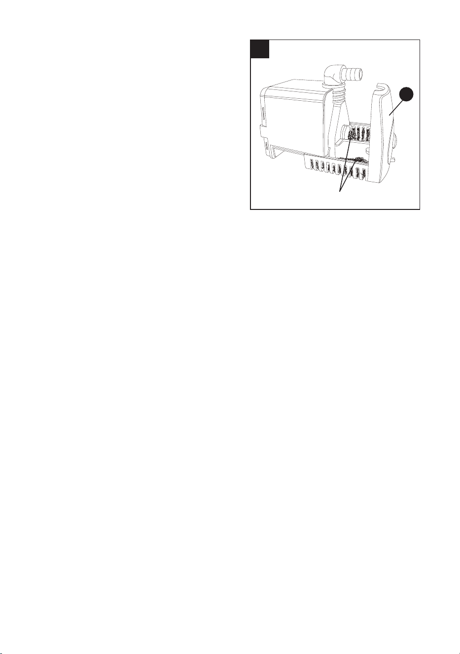
CLEANING THE PUMP (FIG. 49)
For best performance, the pump may be cleaned
periodically.
● Unplug pump before handling or cleaning the
pump.
● Pull out to remove the front cover (1).
● Using a small brush and/or water, clean any
debris or trash that is trapped on the inside
of the pump.
● Replace the front cover (1).
NOTE: To maintain eciency and extend the
life of the pump, check intake screen before
use to make sure it is clean.
CLEANING THE FILTER
For best performance, the lter should be
cleaned periodically.
● Remove the lter from the water tray and
using a water hose run clean water thru the
lter on both sides to remove any debris on
the lter's surface.
● Place lter back into the water tray.
49
1
Pump Filters
44
WARNING
FREE WARNING LABEL REPLACEMENT:
If your warning labels become illegible or are missing, call 803-980-7740 for a free replacement.
DO NOT replace the power cord. If you have any problem or questions concerning the power
cord, call the Customer Service Department at 888-356-2258.

45
Do not service, clean or maintain the saw without rst turning o the motor and unplugging the
saw from the power source. Failure to do so may result in serious personal injury.
PROBLEM POSSIBLE CAUSE CORRECTIVE ACTION
Motor does not
start.
1. Power cord is not plugged into
the outlet.
2. Switch failure.
3. Brush worn.
4. Fuse blown or circuit breaker
tripped on home panel.
1. Plug in properly.
2. Replace switch.
3.
Replace brushes. See MAINTENANCE
section.
4. Verify there is electrical power at the
outlet.
Saw is
overheating.
1. The saw continues to operate too
long under pressure.
2. Blockage or dirt jams the
ventilation slots of the motor.
1. Turn the saw o and let it rest until the
motor is cool to touch.
2.
Check and clean the ventilation slots of
the motor, removing blockage or dirt.
Brush spark
when switch
released.
1. Brush worn. 1. Replace brushes. See
MAINTENANCE section.
The pump is
not owing
water.
1. Water amount is not enough.
2. Water tube is jammed by dirt.
1. Add water until the pump is
submerged completely.
2. Clean the water tube, lter and pump
lter.
Sliding table
is not sliding
smoothly.
1. Dirt or tile dust is jammed too
much on the guide rails or sliding
table rollers.
1. Clean the dirt.
Saw vibrates
or shakes.
1. Saw wheel not round / damaged
/ loose.
2. Wheel not tightened on saw,
arbor nut loose.
1. Replace wheel.
2. Tighten arbor nut.
TROUBLESHOOTING
WARNING
46
REPLACEMENT PARTS LIST
For replacement parts, call our customer service department at 888-3KOBALT (888-356-2258),
8 a.m. - 8 p.m., EST, Monday - Sunday. You could also contact us at [email protected].
H I
Z
MAX
MIN
L
ss
PP
ee
OO
MM
LL
bb
QQ
Ee
K
Gg
DD
Ff
Hh
RR
JJ
Dd
D

47
PART DESCRIPTION PART#
D Rear table extension 530N
H Rip/Angle guide 50L6
I Tile clamp 50KG
K Side splash guard 507Q
L Water pump 528E
Z Filter 50KW
bb Spacers (set of 2) 2FUD
ee Foot pad 2FUH
ss Hitch pin 50KV
DD Drain plug 530P
JJ Water tray lock knob 50P2
LL
Cutting depth stop knob
50K5
MM
Cutting head lock knob
52X3
OO
Wheel wrench
3ZYE
PP
Bevel lock knob
53KY
QQ Rear splash guard 507P
RR Rear table extension lock knob 505H
Dd Safety key 2X21
Ee Sliding T-fence extension lock knob 505H
Ff Carbon brushes (set of 2) 0QQT
Gg 10 mm Hex wrench 531S
Hh Manual 52ZD
DISTRIBUTED BY:
Lowe’s Home Centers LLC
1000 Lowe’s Blvd., Mooresville, NC 28117

48
Printed in Taiwan
The manufacturer will oer replacement parts for this product which under normal usage have
proven to be defective in their manufacture or workmanship for a period of THREE (3) years from
the date of initial retail purchase. This warranty is valid only to the original purchaser. This warranty
is not transferable and does not cover any parts that have been subjected to misuse, abuse,
alteration, overload, accident or normal wear of moving parts. Tools that have been sold “as is,”
sold reconditioned or used as rental equipment are not covered.
Warranty replacement parts can be obtained by contacting the manufacturer at 888-3KOBALT.
Only the manufacturer is authorized to perform warranty service on this product. This warranty
does not apply to accessories or damage caused where repairs have been made or attempted
by others.
The manufacturer is not responsible for direct, indirect, incidental or consequential damages.
Some states do not allow limitations on how long an implied warranty lasts and/or do not allow the
exclusion or limitation of incidental damages, so the above limitations may not apply to you. This
warranty gives you specic legal rights, and you may also have other rights, which vary from state
to state.
The manufacturer makes no warranties, representations or promises as to the quality of its power
tools other than those specially stated in this warranty.
WARRANTY VOID IF PRODUCT USED FOR COMMERICAL PURPOSES.
For replacement parts, call our customer service department at 888-3KOBALT (888-356-2258).
WARRANTY