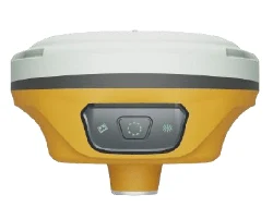
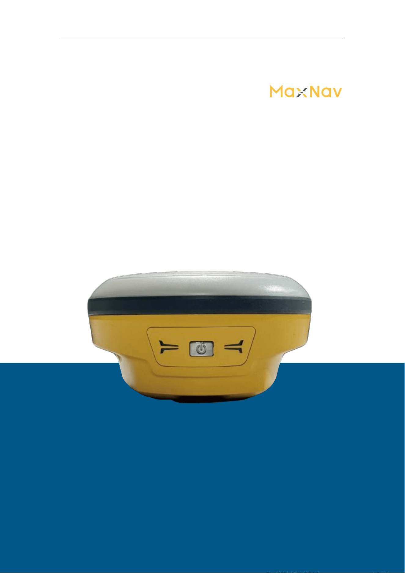
M8 Laser GNSS Receiver
User Guide
1
M8 Laser
GNSS Receiver
User Guide

M8 Laser GNSS Receiver
User Guide
2
Corporate office
MaxNav Technology Ltd.
Ad: 3F, Building 1, No. 400 Fangchun Road, China (Shanghai) Pilot Free Trade Zone, 201203,
Shanghai, China
Tel: +86 21 64056796
Fax: +86 21 54309582
Website:http://www.maxnav.com
E-mail:info@maxnav.com
Trademark notice
© 2026 MaxNav Technology Ltd. All rights reserved.
Copyright Notice
This is the V1.0 (February, 2026) revision of the M8 User Guide. It cannot be copied or
translated into any language without the written permission of MaxNav Technology Ltd.
Technical Assistance
If you have any question and can't find the answer in this manual, please contact your local dealer
from which you purchased the
M 8
. Alternatively, request technical support from MaxNav
Technology Website: www.maxnav.com or technical support email:
info@maxnav.com
. Your
feedback about this Guide will help us to improve it with future revisions.
Safety Information
Before using the receiver, please make sure that you have read and understood this User Guide, as
well as the safety requirements.
⚫
Connect your devices strictly based on this User Guide
⚫ Install the GNSS receiver in a location that minimizes vibration and moisture
⚫
Avoid falling to ground, or colliding with other items

M8 Laser GNSS Receiver
User Guide
3
⚫
Keep a sound ventilation environment
⚫
Change the cable if damaged
Related Regulations
The receiver contains integral Bluetooth® wireless technology. Regulations regarding the use
of the datalink vary greatly from country to country. In some countries, the unit can be used
without obtaining an end-user license. But in some countries the administrative permissions are
required. For license information, please consult your local dealer.
Use and Care
The receiver can withstand the rough treatment that typically occurs in the field. However, the
receiver is high-precision electronic equipment and should be treated with reasonable care.
Warning and Caution
An absence of specific alerts does not mean that there are no safety risks involved. A Warning or
Caution information is intended to minimize the risk of personal injury and/or damage to the
equipment.
WARNING- A Warning alerts you to a potential risk of serious injury to your person and/or damage to
the equipment, because of improper operations or wrong settings of the equipment.
CAUTION- A Caution alerts you to a possible risk of damage to the equipment and/or data loss.
Warranty Notice
MaxNav Technology does not warranty devices damage because of force majeure (lighting, high
voltage or collision).
MaxNav Technology does not warranty the disassembled devices.

M8 Laser GNSS Receiver
User Guide
4
FCC Warning
This device complies with part 15 of the FCC rules. Operation is subject to the
following two conditions: (1) this device may not cause harmful interference, and
(2) this device must accept any interference received, including interference that
may cause undesired operation.
Changes or modifications not expressly approved by the party responsible for
compliance could void the user's authority to operate the equipment.
NOTE: This equipment has been tested and found to comply with the limits for a
Class B digital device, pursuant to part 15 of the FCC Rules. These limits are
designed to provide reasonable protection against harmful interference in a
residential installation. This equipment generates uses and can radiate radio
frequency energy and, if not installed and used in accordance with the instructions,
may cause harmful interference to radio communications. However, there is no
guarantee that interference will not occur in a particular installation. If this
equipment does cause harmful interference to radio or television reception, which
can be determined by turning the equipment off and on, the user is encouraged to
try to correct the interference by one or more of the following measures:
• Reorient or relocate the receiving antenna.
• Increase the separation between the equipment and receiver.
• Connect the equipment into an outlet on a circuit different from that to which
the receiver is connected.
• Consult the dealer or an experienced radio/TV technician for help
RF Exposure Information
This equipment complies with FCC radiation exposure limits set forth for an
uncontrolled environment. This equipment should be installed and operated with
minimum distance 20cm between the radiator and your body.

M8 Laser GNSS Receiver
User Guide
5
Contents
1. Introduction
..............................................................................................................................1
1.1. About the receiver ...............................................................................................................1
1.2. Receiver features .................................................................................................................1
1.3. M8 parts list ........................................................................................................................1
1.3.1 Basic Supply kit .............................................................................................................2
2. Setting up the receiver ............................................................................................................. 3
2.1. Environmental requirements
................................................................................................3
2.2. Laser & Cameras Specification ..............................................................................................4
2.3. Front panel
......................................................................................................................... 4
2.4. Lower housing .....................................................................................................................5
2.5. Power supply
...................................................................................................................... 5
2.5.1 Internal battery .............................................................................................................. 5
2.5.2 External Power Supply ...................................................................................................5
2.5.3 Charge Battery via M8 ................................................................................................... 6
2.6 Pole-mounted setup .............................................................................................................7
3. General Operation
....................................................................................................................7
3.1 Button functions
....................................................................................................................7
3.2 LED behavior........................................................................................................................ 7
3.3 Receiver Web GUI interface.................................................................................................... 9
3.3.1 Checking the receiver status ......................................................................................... 10
3.3.2 Configuration .............................................................................................................. 12
3.3.3 Receiver Management ..................................................................................................15
4. Static survey ........................................................................................................................... 21
4.1 Receiver Configuration
....................................................................................................... 21
4.2 Static Data Collection ..........................................................................................................22
4.3 Static Data Download ......................................................................................................... 22
4.4 Rinex Convert .....................................................................................................................22
5. Real-Time Kinematic Survey (RTK)
..........................................................................................25
5.1 Installation of Mfield .......................................................................................................... 25
5.2 Wizard function in Mfield ................................................................................................... 25
5.3 Start a New Project .............................................................................................................27
5.4 Connection
........................................................................................................................ 29
5.5 Work Mode
........................................................................................................................31
5.5.1 Start Rover with internal radio mode .......................................................................... 31
5.5.2 PDA CORS mode ........................................................................................................ 33
6. Basic Survey Functions
........................................................................................................... 35
6.1 Topo survey ....................................................................................................................... 35
6.1.1 Survey settings ............................................................................................................ 37

M8 Laser GNSS Receiver
User Guide
6
6.1.2 IMU Measurement .......................................................................................................38
6.1.3 Laser Measurement ......................................................................................................39
6.1.4 Visual Measurement .................................................................................................... 41
6.2 Auto survey/Area survey
.....................................................................................................42
6.3 Stake Points/Lines .............................................................................................................. 43
6.3.1 Stakeout Points ............................................................................................................43
6.3.2 Visual Stakeout ............................................................................................................44
6.3.3 Stake line .................................................................................................................... 44
7. CAD ........................................................................................................................................45
7.1 CAD Menu
......................................................................................................................... 48
7.2 CAD Drawing ......................................................................................................................48
7.2.1 Point
........................................................................................................................... 49
7.2.2 Line ............................................................................................................................. 50
7.2.3 Polyline
........................................................................................................................51
7.2.4 Curve .......................................................................................................................... 53
7.2.5 Arc
.............................................................................................................................. 54
7.2.6 Square .........................................................................................................................56
7.2.7 Square-c
...................................................................................................................... 57
7.2.8 Rectangle .....................................................................................................................59
7.2.9 Rectangle-c
..................................................................................................................60
7.2.10 Polygon ..................................................................................................................... 62
7.2.11 Circle 2p .................................................................................................................... 63
7.2.12 Circle 3p .................................................................................................................... 65
7.2.13 Note
..........................................................................................................................67
7.3 CAD Survey
........................................................................................................................ 68
7.3.1 Int 4 point
....................................................................................................................68
7.3.2 Int 2 dist ...................................................................................................................... 70
7.3.3 Int entity ......................................................................................................................73
7.3.4 Single offset intersection .............................................................................................. 75
7.3.5 Double offset intersection .............................................................................................79
7.3.6 Number equal parts
..................................................................................................... 82
7.3.7 Distance equal parts .....................................................................................................84
7.3.8 Rectangle corner
..........................................................................................................86
7.3.9 Area ............................................................................................................................ 89
7.3.10 Area Division
..............................................................................................................91
7.3.11 Angle calculate ...........................................................................................................94
7.3.12Two-Point Distance
..................................................................................................... 97
7.3.13 Point to Line ...............................................................................................................98
7.4 CAD Stake
........................................................................................................................ 101
7.5 CAD Setting ......................................................................................................................104

M8 Laser GNSS Receiver
User Guide
7
7.6 CAD Align
.........................................................................................................................104
8. Stake Surface ........................................................................................................................105
9. PPK .......................................................................................................................................106
10.Site Calibration/Grid Shift
....................................................................................................107
10.1 Site calibration
............................................................................................................... 107
10.2 Grid Shift ........................................................................................................................109
10.3 COGO
............................................................................................................................ 109
11.Data Export/Import ............................................................................................................. 110
11.1 Import ........................................................................................................................... 110
11.2 Export
............................................................................................................................112
12.Export Result ....................................................................................................................... 113
12.1 NMEA 0183 output
.........................................................................................................113
12.2 Register M8 via Mfield
....................................................................................................114
➢ Register function..............................................................................................................114
13.Firmware Upgrade ...............................................................................................................115
Appendix: Physical Parameter of Modules inside of M8 ...............................................................117

M8 Laser GNSS Receiver
User Guide
1
1. Introduction
The MaxNav M8 User Guide is aimed to help you get familiar with the M8 laser GNSS
receiver and start your project effectively. We highly recommend you to read this
manual before surveying, even you have used other GNSS receivers before.
1.1. About the receiver
M8 can be applied in RTK mode with all GNSS constellations. It has ultra-small size and
strong anti-interference ability to make it possible to work even in harsh environments.
It is the ideal RTK/GNSS product for surveyors.
1.2. Receiver features
The M8 laser key features:
• Utra small and super light
- Size: ≤11cm
- Weight:≤500g with internal battery
• 1668 channels of simultaneously tracked satellite signals
• Increased measurement traceability with ® Quantum™ algorithm
technology
• Cable-free Bluetooth wireless technology
• 2 LEDs, indicating Satellites Tracking and RTK Corrections data
• IP68 Dust- and waterproof for harsh environments
• Calibration-free IMU integrated for Tilt Survey
• Up to 60° tilt with 2.5 cm accuracy
• With two camera, surveyors gain a 3D visual view in topo survey and stake work.
• Support SBAS and PPP service
• Support NFC Fast Connection
• Support super datalink, supports a number of protocols,
including Transparent /TT450S/South/Mac/Maxlink/Maxlink+.
With Maxlink and Maxlink+, 5-15km working range is achievable under ideal
conditions.(Note: Internal Radio mode can only be used for the rover station.)
• Support long baseline E-RTK™ (Beidou B3 signal is included in RTK
calculate engine)
1.3. M8 parts list
This section provides overall M8 parts list, including basic supplies and customized kits
based on your requirements.
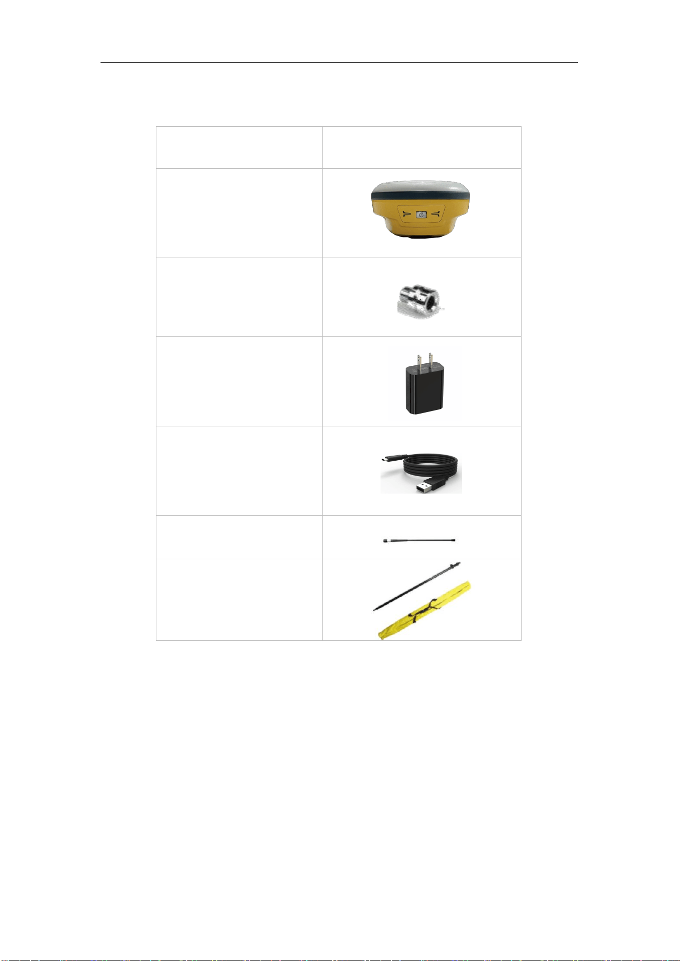
M8 Laser GNSS Receiver
User Guide
2
1.3.1 Basic Supply kit
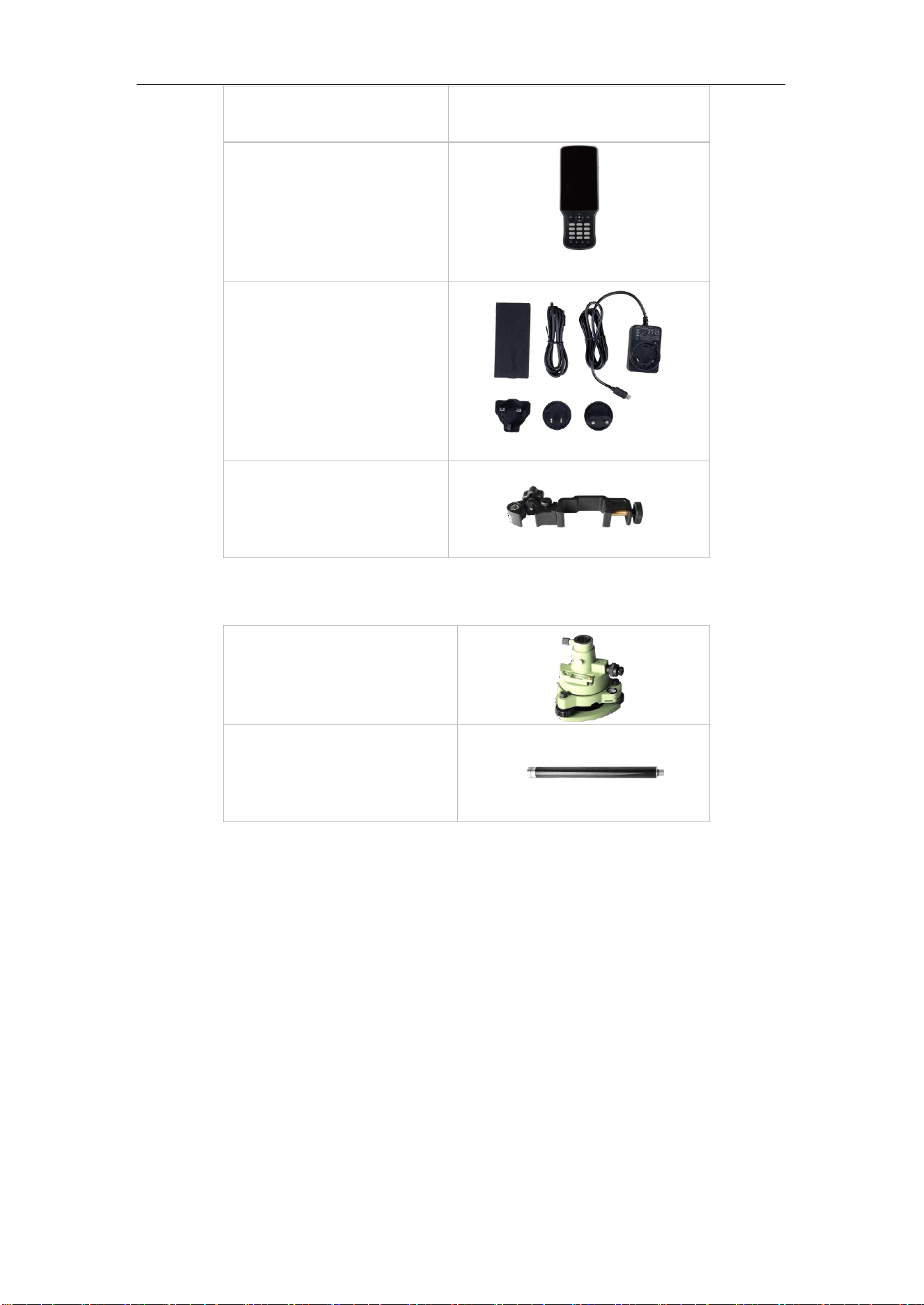
The M8 Basic Supply kit contains one receivers and related accessories
Item
Picture
1* Kits M8 Receivers
1*GNSS Connector
1*Charger adapter
(EU/USA/UK)
1*USB—Type-C cable
2* Whip Antenna (UHF)
1*2m-Range Pole with yellow
bag
M8 Laser GNSS Receiver
User Guide
3
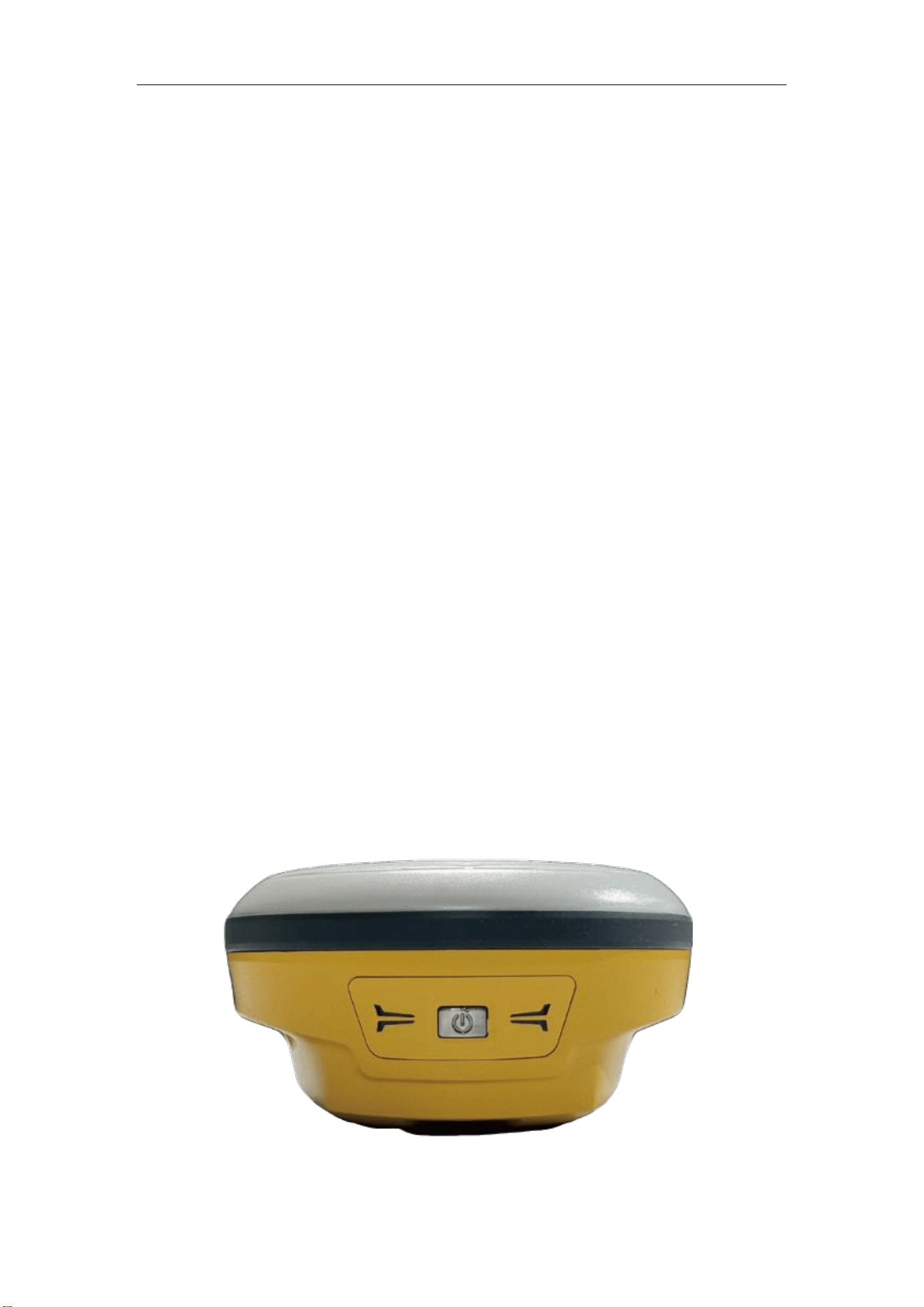
Item
Picture
C50 Controller
Controller Battery, Charger
and Cable
Controller Bracket
Optional accessories:
Double Bubbles Tribrach with
High Adapter
1* 30cm Extension bar
2. Setting up the receiver
This chapter provides general information on environmental requirements, setup,
power supply and connection of the M8.
2.1. Environmental requirements
To keep the receiver with a reliable performance, it is better to use the receiver in safe
environmental conditions:
• Operating temperature: -20°C to 65°C
• Storage temperature: -40°C to 85°C
• Out of corrosive fluids and gases
• With a clear view of sky
M8 Laser GNSS Receiver
User Guide
4
2.2. Laser & Cameras Specification
To keep the laser with a reliable performance, It is better to use M8 in the conditions
that meet the specifications:
Laser specification
• Range: 50m
• Accuracy(room temperature): (3-5)mm + 1ppm
• Measuring Frequency: Classic Value: 3Hz
• Maximum Value: 5Hz
• Laser Injection Power: 0.9mW to 1.5mW
• Working Temperature: -20°C to +50°C
• Storage Temperature: -30°C to +60°C
Cameras specification
•Sensor pixels: 2 cameras with 2 MP global shutter
•Field of view: 75°
•Video frame rate: 30 fps
Image group capture:
•Rate: typically 2 Hz, up to 25Hz
•Max capture time: 60s with an image group size of 60MB
2.3. Front panel
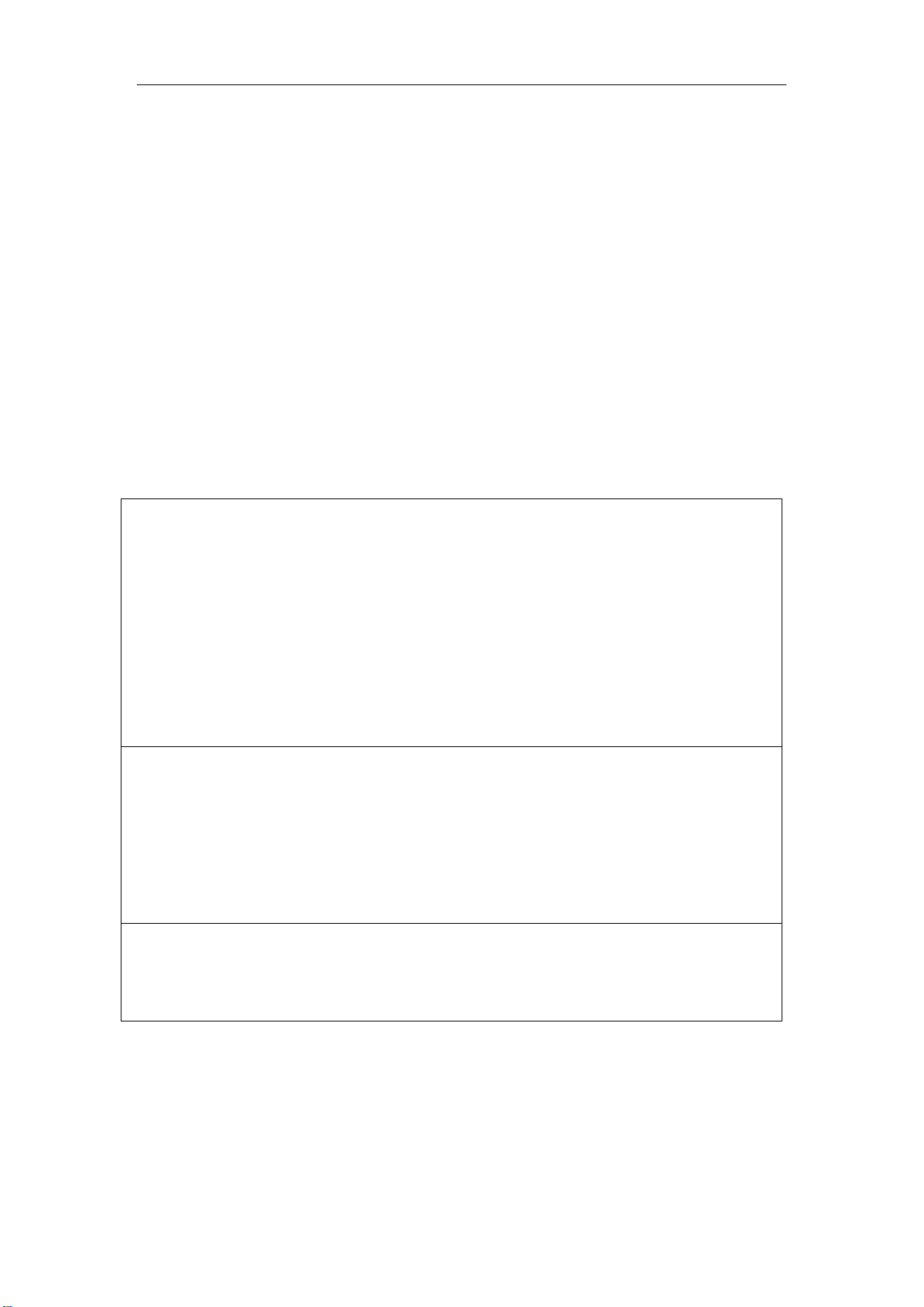
Receiver front panel contains 2 buttons, Power button and Record button. The LEDs
display shows the status of differential, satellite tracking and charge indicator. For
detailed information, see 3.2.
M8 Laser GNSS Receiver
User Guide
5
2.4. Lower housing
Receiver lower housing contains a type-c port, UHF radio antenna connector and a
threaded insert.
2.5. Power supply
M8 supports internal battery and external power input.
2.5.1 Internal battery
The M8 receiver adopts the rechargeable Lithium-ion battery design that provides you
an effective survey workflow. The internal battery typically provide about 16-hour
operating time as a rover. However, this operating time varies based on environmental
conditions
Battery Safety
Charge and use the battery only in strict accordance with the instructions below:
– Do not use or charge the battery if it appears to be damaged. Signs of damage
include, but are not limited to, discoloration, warping, and leaking battery
fluid.
– Do not expose the battery to fire, high temperature, or direct sunlight.
– Do not immerse the battery in water.
– Do not use or store the battery inside a vehicle during hot weather.
– Do not drop or puncture the battery.
– Do not open the battery or short-circuit its contacts.
Charging the Lithium-ion Battery
Please obey the following instructions when charging your batteries:
– Charge the battery completely before using it for the first time.
– Fully charge takes approximately 6 hours per battery at room temperature.
– If the battery has been stored for a long time, charge it before your field work.
– Re-charge the battery at least every three months if it is to be stored for long
time.
Dispose of the Lithium-ion Battery
– Discharge a Lithium-ion battery before dispose of it.
– Dispose of batteries is an environmentally sensitive manner, and adhere to any
local and national regulations concerning battery disposing or recycling.
WARNING – Do not damage the rechargeable Lithium-ion battery. A damaged battery can cause an
explosion or fire, and can result in personal injury and/or property damage.
2.5.2 External Power Supply
The receiver is connected to an external power supply through a Type-C cable, and
make sure that use an external power supply with the correct voltage of M8, such as a
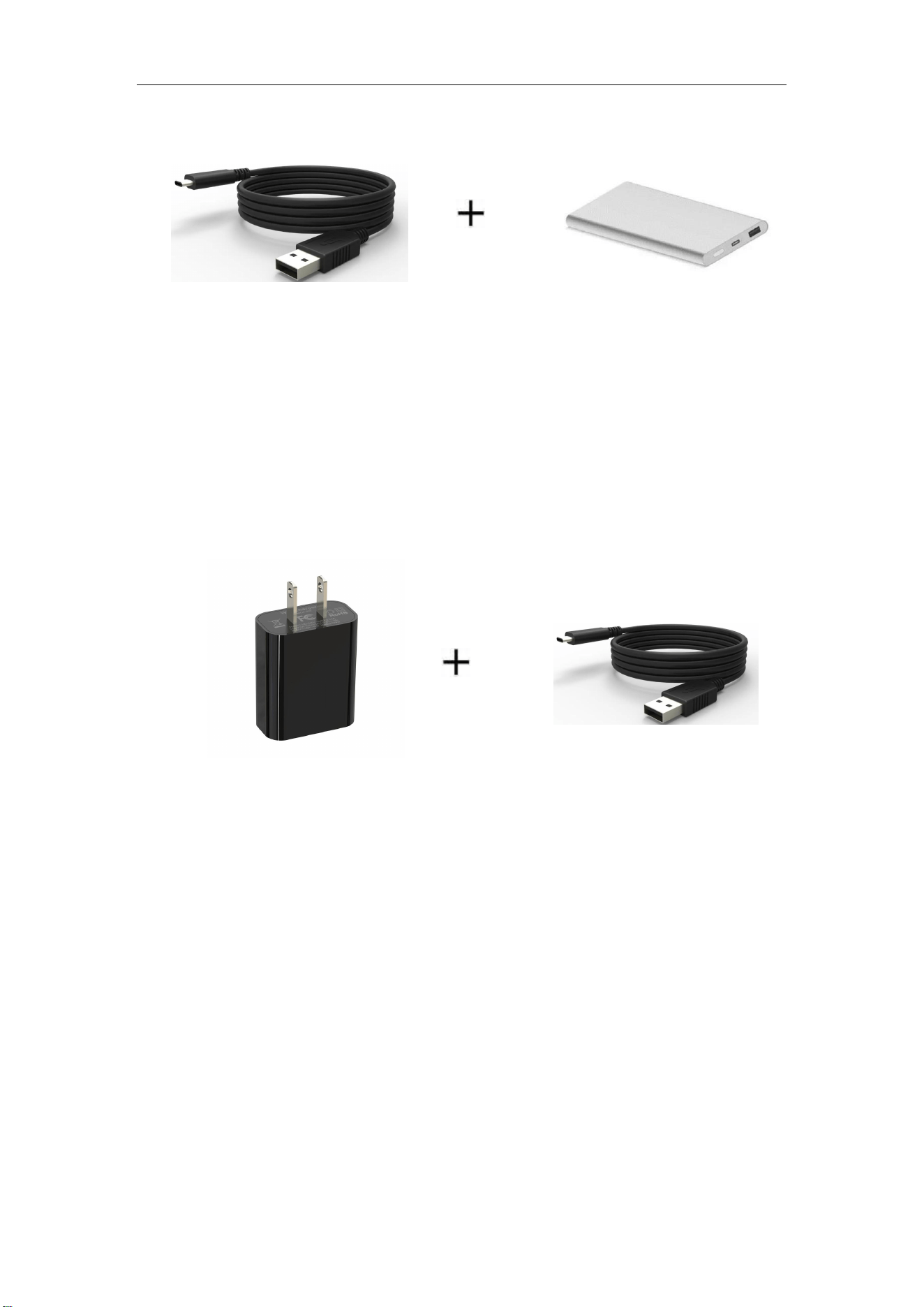
M8 Laser GNSS Receiver
User Guide
6
5-9V power bank. Over-voltage function cannot protect your M8 if reverse connection.
2.5.3 Charge Battery via M8
M8 GNSS Receiver can work with a Type-C charger, it means you can charge batteries
directly.
• Power off M8 receiver with batteries inside;
• Connect M8 receiver to Adaptive charger with type-c cable;
• Receiver charge the battery, the red power led will flashing during charging and will
off when battery full
M8 Laser GNSS Receiver
User Guide
7
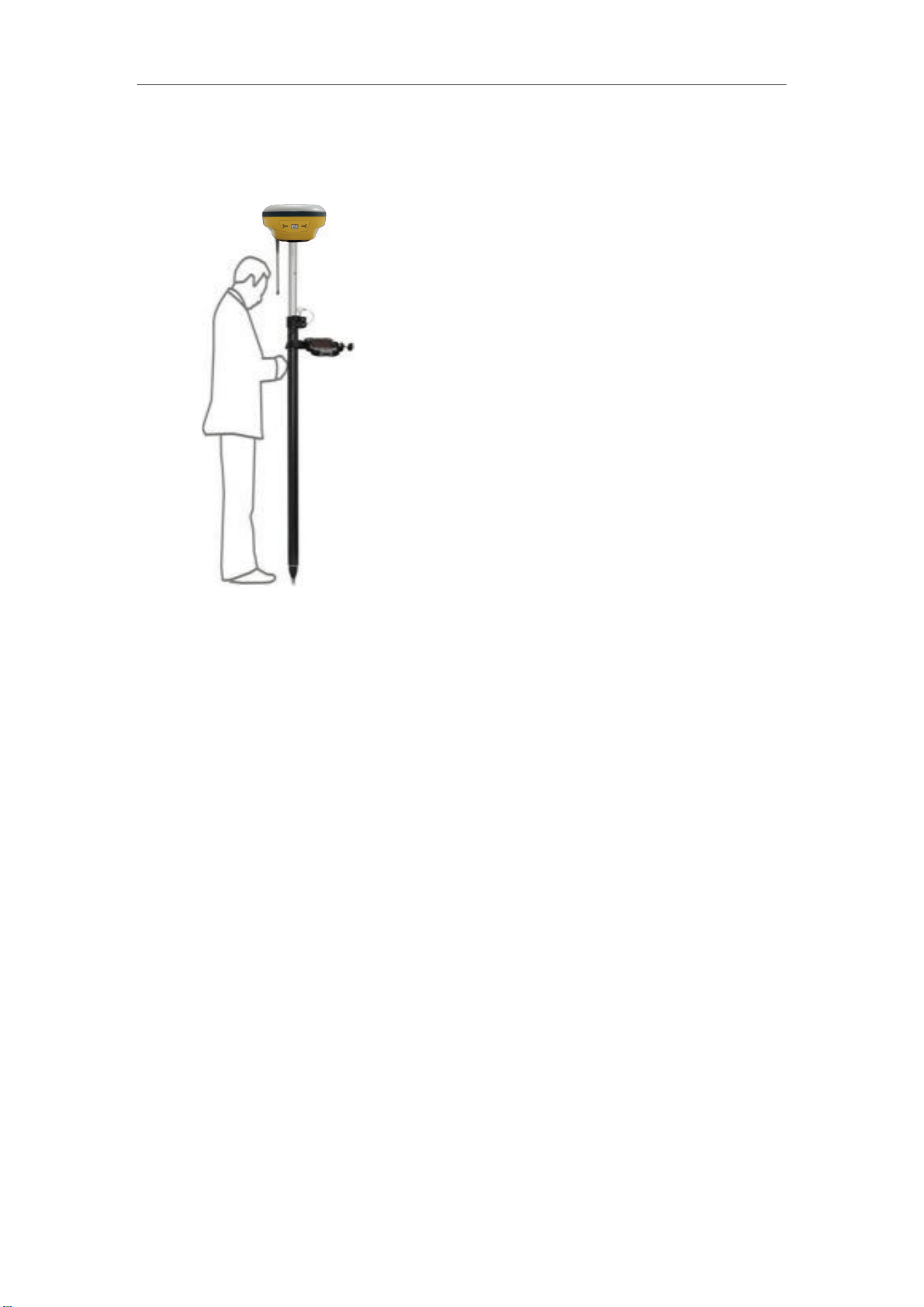
2.6 Pole -mounted setup
To mount the receiver on a range pole as the figure shown below:
Tip: Do not tightly clamp the controller on the Range Pole.
3. General Operation
This chapter introduces all controls for the general operation, including button
functions and all LED behaviors on the front panel.
3.1 Button functions
To turn off the receiver, long press the button for 3-4 seconds until all LEDs off.
There are one power button on the front panel.
• Power button:
Press the power button for about 1 second to turn on the receiver, the orange indicator
lights up fully then turns off. The satellite indicator and differential indicator flash green
twice in sequence. The buzzer sounds continuously, then the device powers on.
To turn off the receiver, long press the button for 3-4 seconds until all LEDs off.
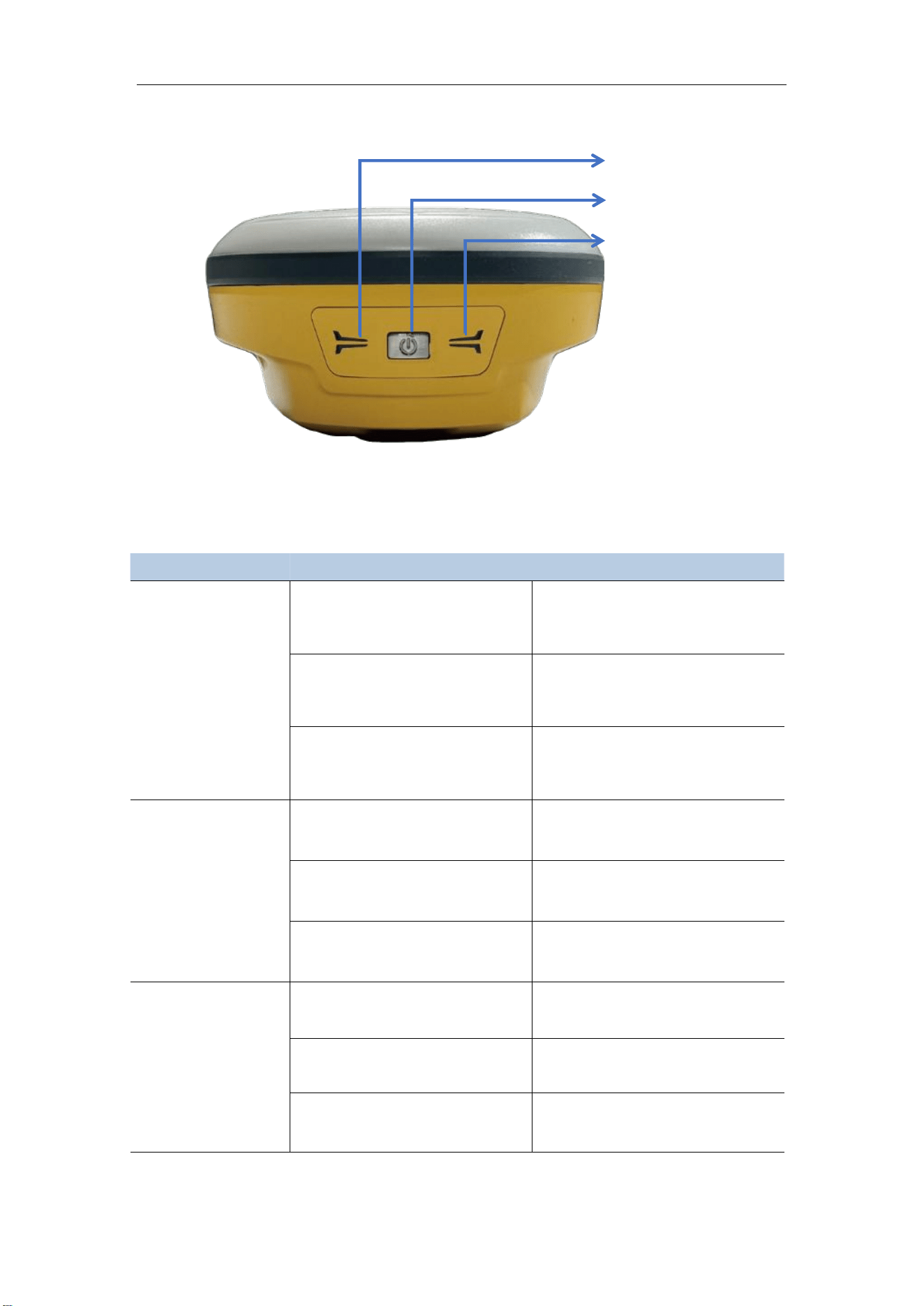
3.2 LED behavior
The LEDs on the front panel indicate receiver working status. Generally, a lit or slowly
flashing indicates normal operation, and an unlit LED indicates that no operation is
Thread the receiver onto the range pole
Mount the controller bracket to the pole
Install the controller into the bracket
M8 Laser GNSS Receiver
User Guide
8
occurring. The following table define each possible LED state:
LEDs
States
Description
Power
Satellite Tracking indicator
flashing green, differential
data indicator off.
Battery is blew 50%
Satellite Tracking indicator
solid green, differential data
indicator flashing green.
Battery is above 50% and
below 100%.
Both satellite Tracking
indicator and differential data
indicator solid green.
Battery is 100%.
Differential
Data(right side)
Green light flashes once every
2 seconds.
No satellite received
Green light flashes twice
quickly.
Single Point
Green light flashes rapidly.
Fixed
Satellite
Tracking(left side)
Green light flashes once every
2 seconds.
No satellite received
Green light flashes twice
quickly.
Single Point
Green light flashes rapidly.
Fixed
Satellite Tracking
Power
Differential Data
M8 Laser GNSS Receiver
User Guide
9
3.3 Receiver Web GUI interface
Step 1: Connect Wi-Fi of M8 receiver
Turn on the M8 GNSS receiver and wait for the M8 serial number to appear under the
available Wi-Fi networks on your smart phone or office computer.
For example, M8-M81LXXXXX (where xxxxx represents the last five digits of the receiver
serial number).
Enter password: 12345678
Step 2: Login the Web
Select the receiver, open a web browser and then enter the following IP address:
http://192.168.1.8
Tip: Most web browsers for computers / laptops and smart phones / PDAs
support the receiver Web GUI
Step 3: Enter the default login settings to access the main page
Username: admin
Password: admin
After accessing the main page, configuration menus are listed on the left, and receiver’s
settings on the right. Each configuration menu will be demonstrated in the following
sections.
M8 Laser GNSS Receiver
User Guide
10
3.3.1 Checking the receiver status
In the section, you can check System information, Status, 4G Network, Bluetooth, Wifi,
Position info, satellite info.
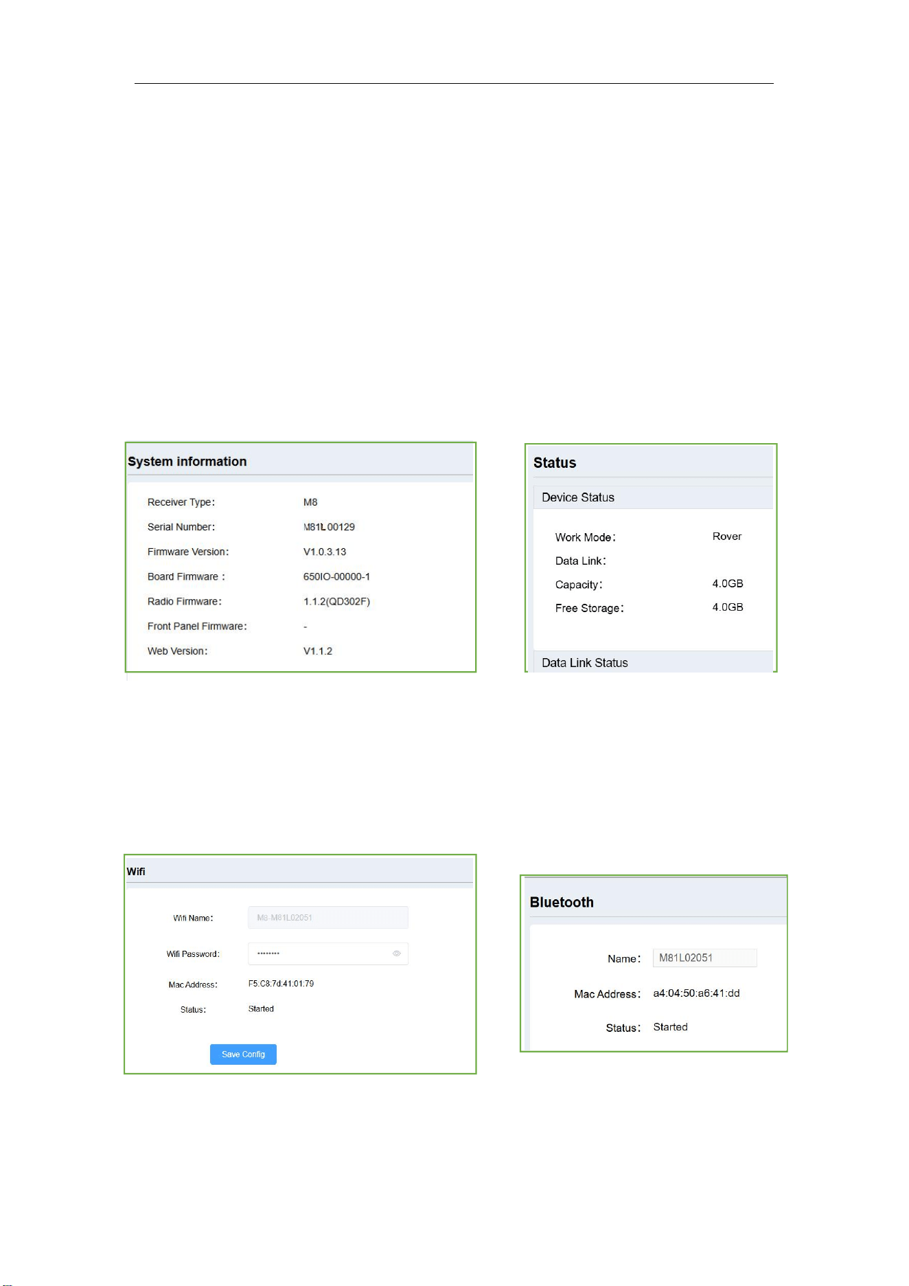
(1) System information, includes the basic information includes receiver type, serial
number, system firmware version, board firmware version, radio firmware (radio type),
front panel firmware (M8 doesn’t have front LCD panel), Web version.
(2) Status: Show the device status and data link status, includes work mode, data link,
internal storage capacity and current free storage. The default work mode is rover with
the new device. Data link status will vary from different work mode, the default is null.
(3) WIFI information, shows WIFI name, current Wifi password and Mac address. The
Wifi password is 12345678, the client can change the password, click Save config to
save configuration; Bluetooth information, shows Bluetooth name and Mac address,
Bluetooth name cannot be changed
M8 Laser GNSS Receiver
User Guide
11
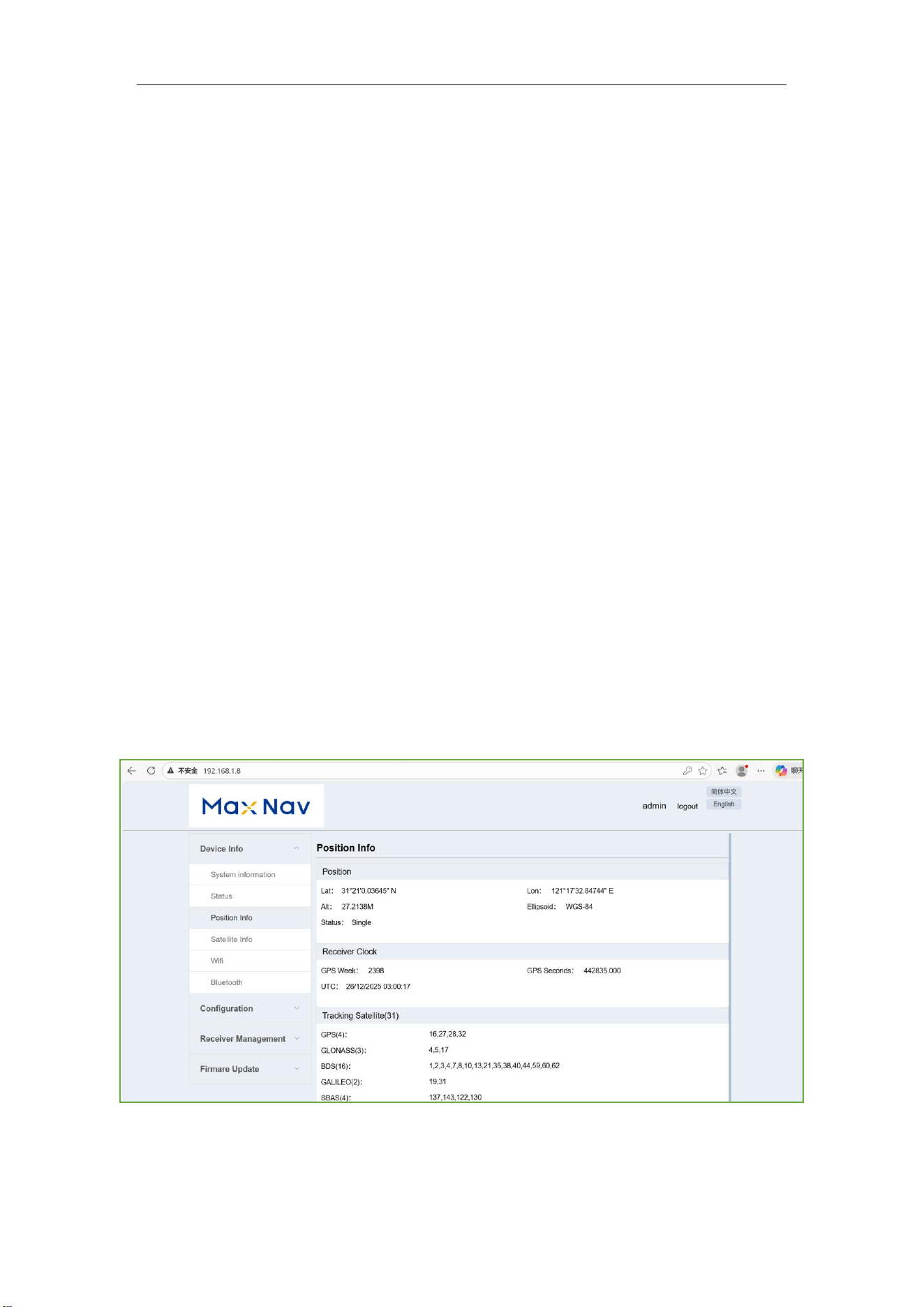
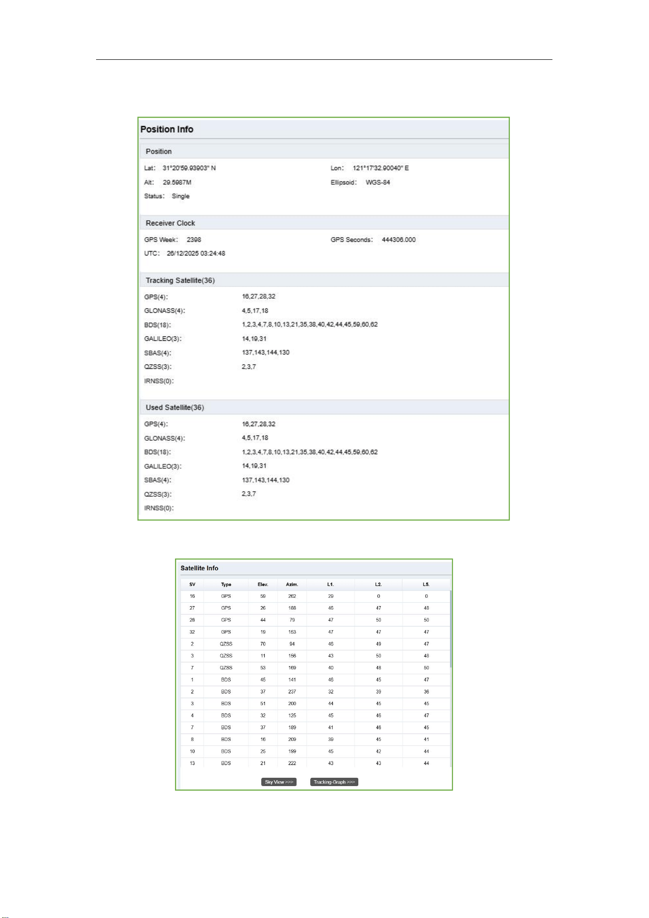
(4) Position info, shows position status, clock status, tracking satellites, used satellites
and DOP status.
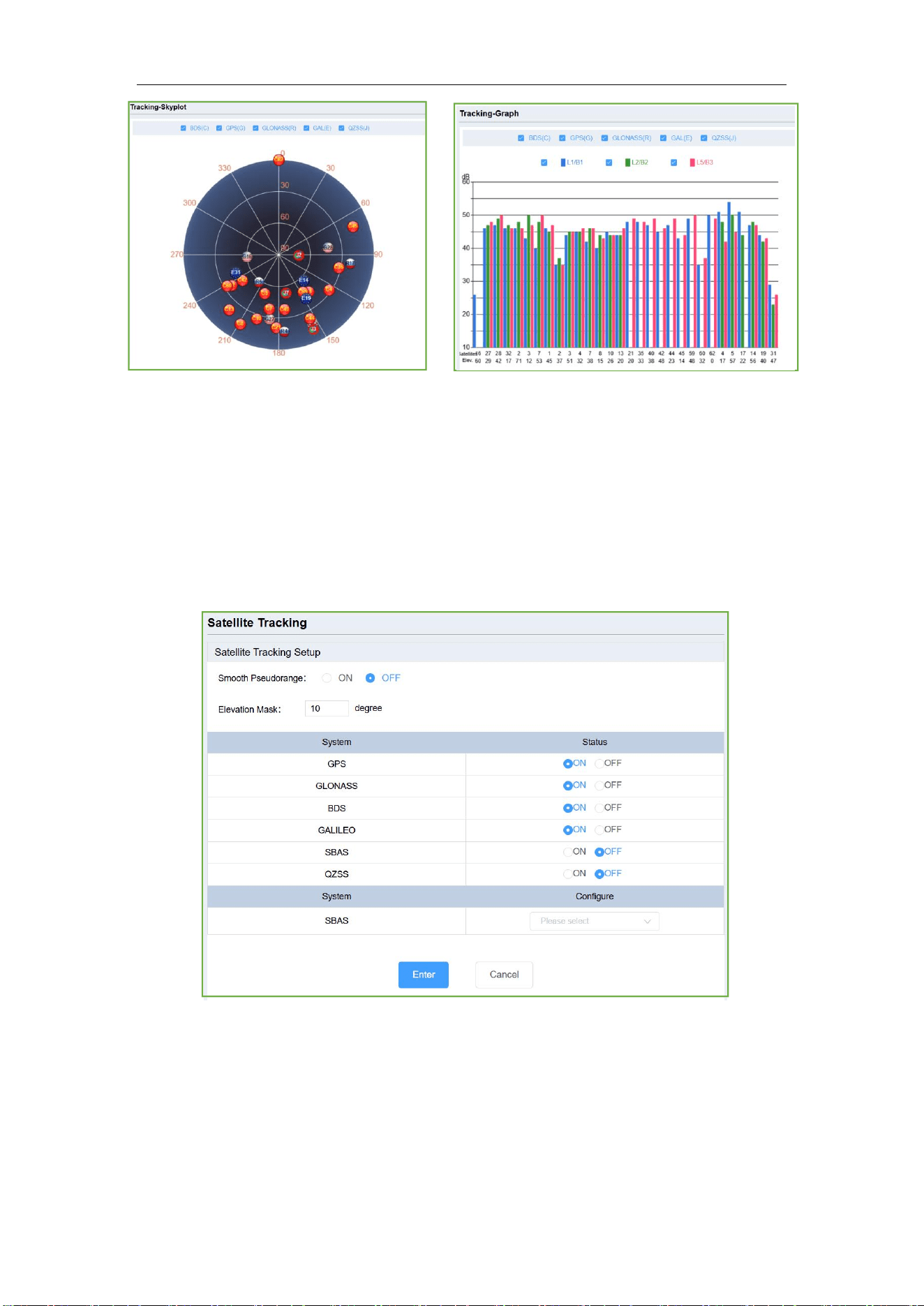
(5) Satellites Info, includes Tracking graph, Tracking skyplot.
M8 Laser GNSS Receiver
User Guide
12
3.3.2 Configuration
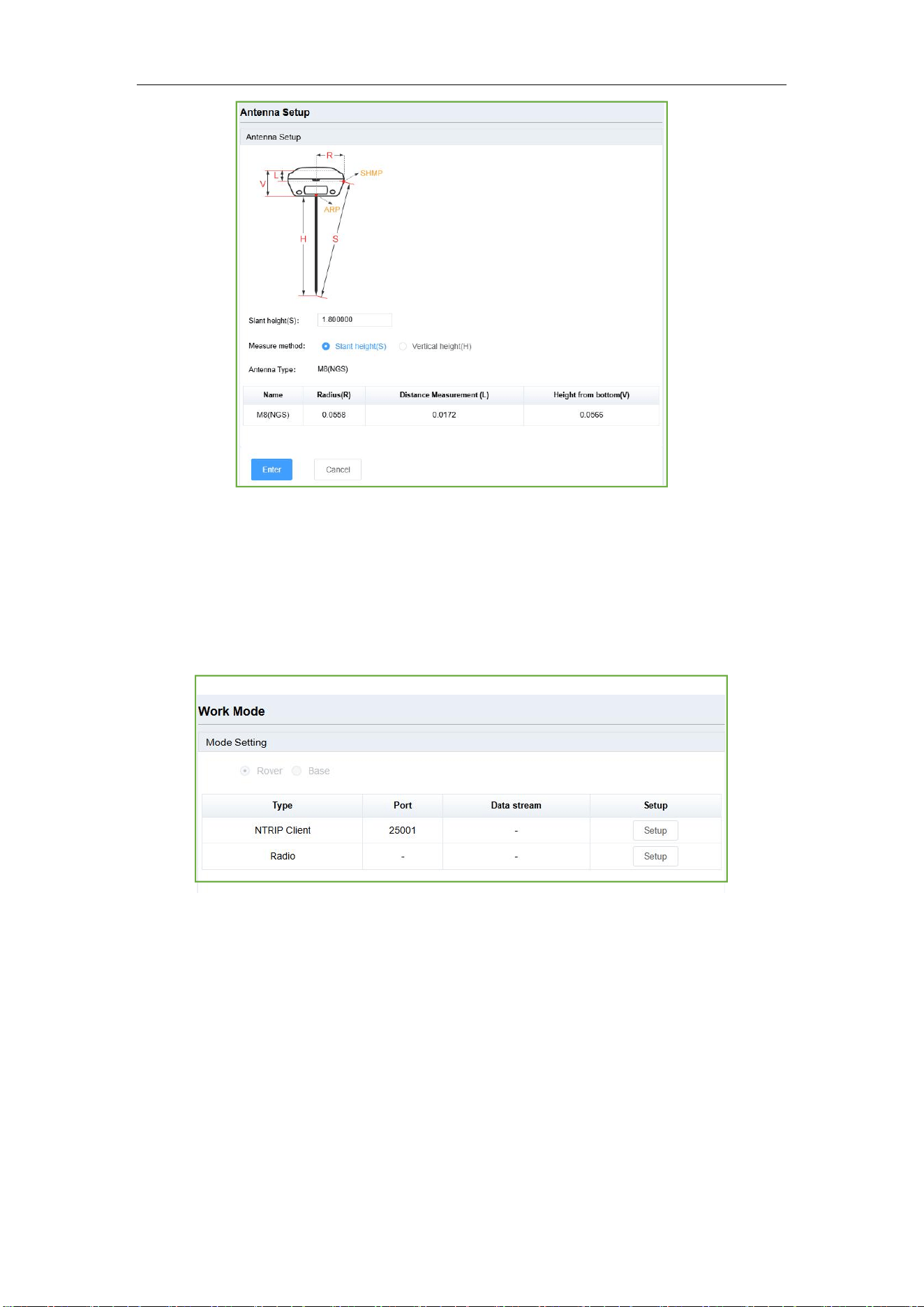
This section includes Satellite tracking, work mode and Antenna setup configuration.
• Satellite tracking, includes Smooth Pseudorange, default is OFF; Elevation mask:
default is 10 degrees; and every system status, supports to change by customers, click
Enter to save settings, click Cancel to cancel the settings.
• Antenna setup: measure method supports Slant height and vertical height, choose
Antenna type, and setup antenna height, click Enter to save configuration.
M8 Laser GNSS Receiver
User Guide
13
•
Work mode, includes rover settings.
Rover settings include Ntrip Client (Same with PDA CORS in Mfield) and Radio (Same
with internal radio in Mfield).
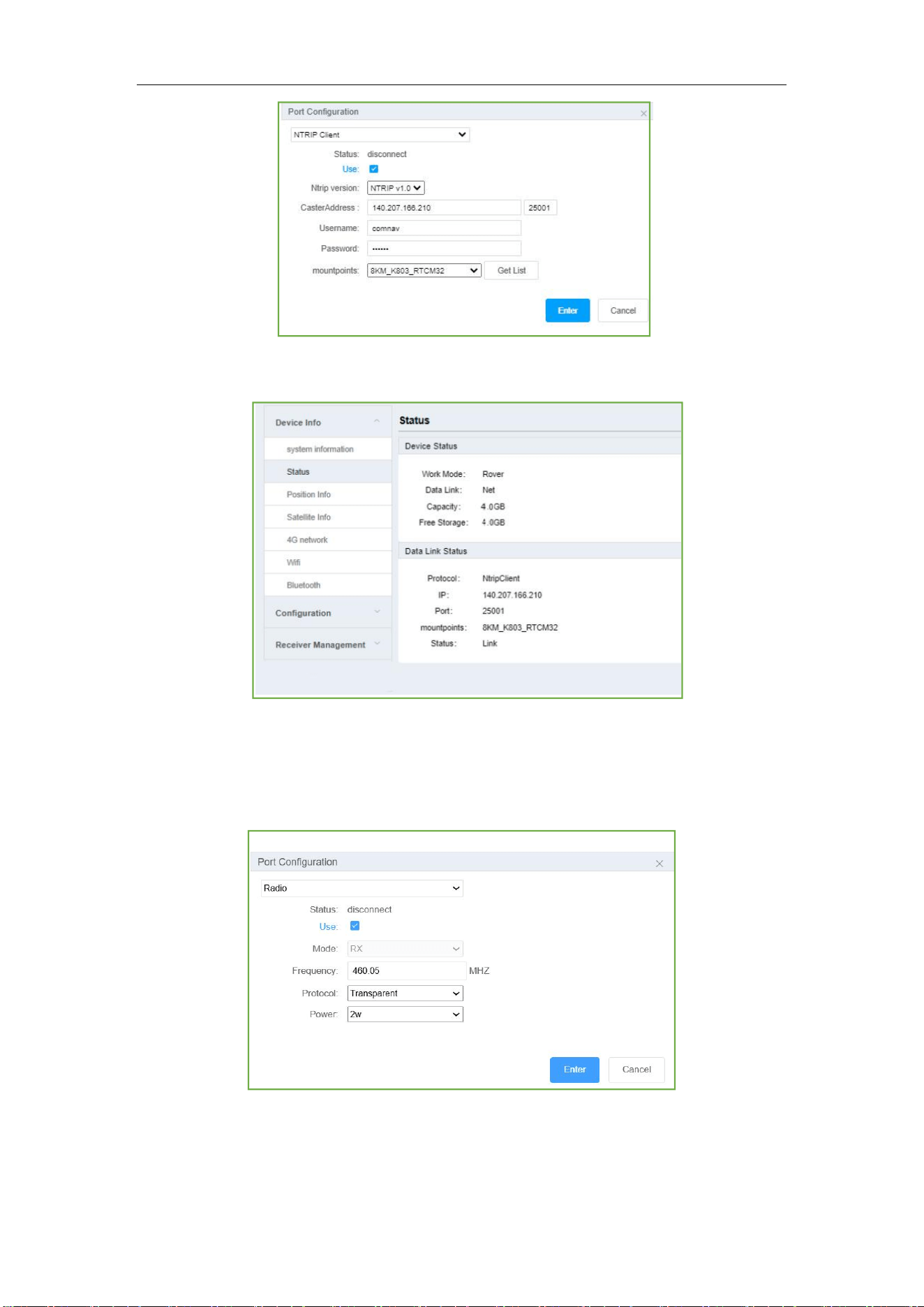
(1) Ntrip Client: Set Ntrip version, includes NTRIP v1.0 and NTRIP v2.0, IP, port,
username, password, then click Get List and select mountpoint, check on Use, click
Enter to apply the Ntrip Client; Check off Use, click Enter to cancel the work mode.
M8 Laser GNSS Receiver
User Guide
14
When setup the Ntrip Client, you can go to Device Info->Status to check current device
status and datalink status.
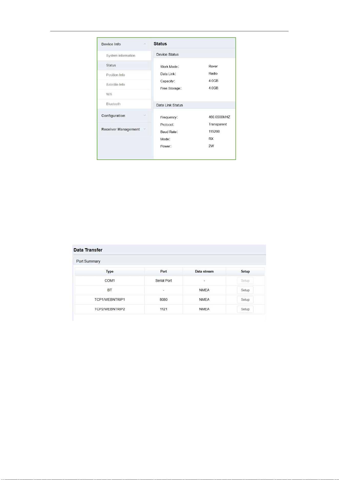
(2) Radio: The model is RX, set the frequency, minimum interval is 12.5 KHz; the
protocol is Transparent; set the power, supports 0.5w, 1w and 2w; check on Use, click
Enter to apply the internal radio; Check off Use, click Enter to cancel the work mode.
After setup, you can go to Device Info->Status to check device status.
M8 Laser GNSS Receiver
User Guide
15
3.3.3 Receiver Management
This section includes Data Transfer, Data record, Data Download and Receiver Utility.
3.3.3.1 Data Transfer
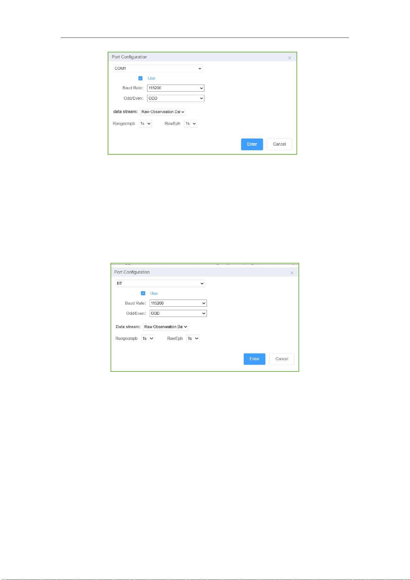
Data transfer has four types: Com1, BT, TCP1/WEBNTRIP1, TCP2/WEBNTRIP2.
•
Com1: This is setup to transfer the data through com1 port of the OEM board inside.
You can use serial port cable to check the data transmission (the lemo port is connected
to Com1 of the OEM board inside).
(1) Baud rate supports 115200, 57600, 38400, 19200, 9600, the default is 115200.
(2) The supported file formats include raw observation data, NEMA, RTCM3.2,
RTCM3.2(MSM5), RTCM3.0, RTD, CMR.
(3) Observation and ephemeris output frequency support 1s, 2s, 5s, 10s and 15s.
M8 Laser GNSS Receiver
User Guide
16
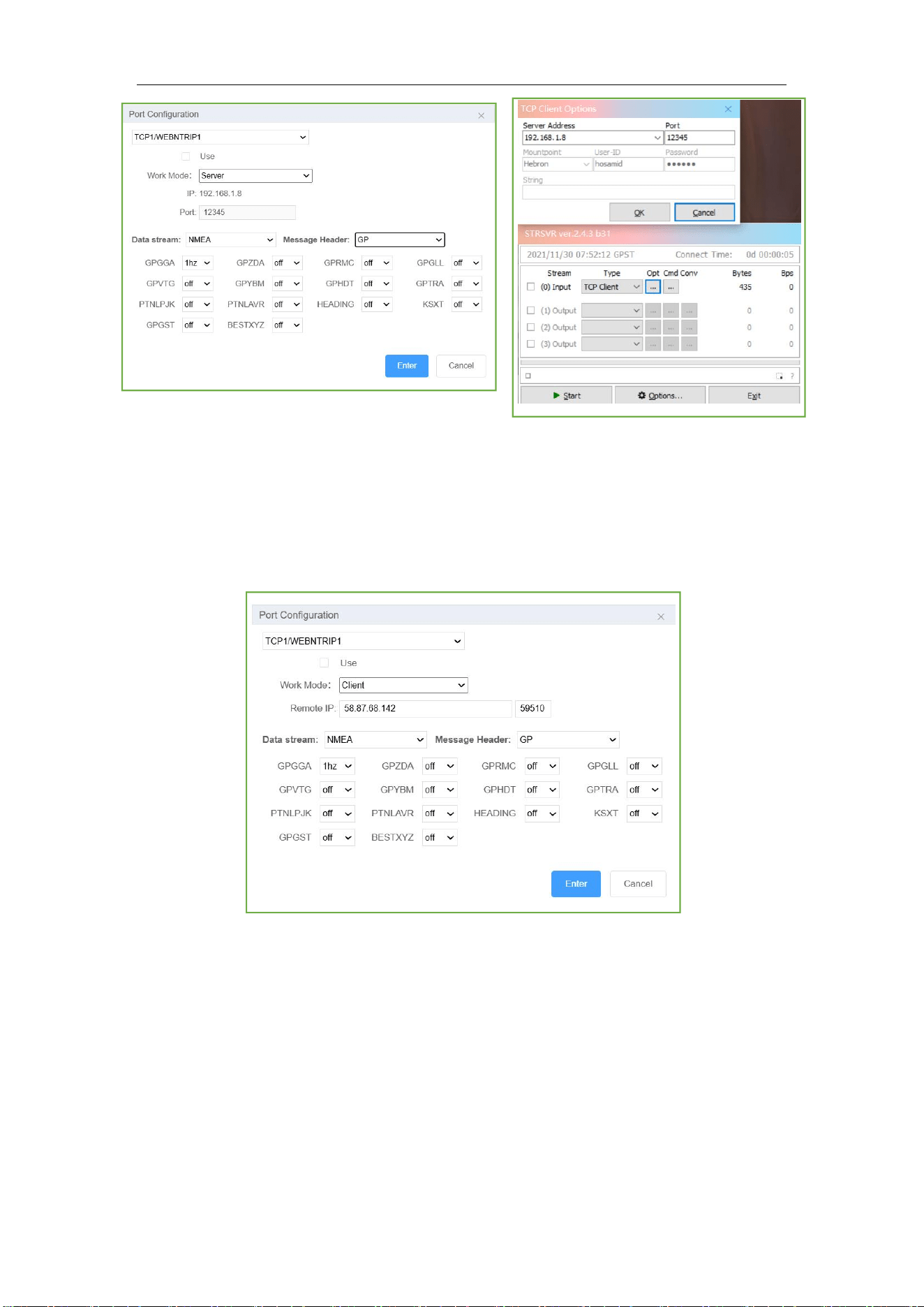
• BT: This is used to output data through the OEM board (connected to the Bluetooth
modem), you can output NMEA data via this port, it is the important step to connect
the receiver to other brand software.
(1) Baud rate supports 115200, 57600, 38400, 19200, 9600, the default is 115200.
(2) The supported file formats include raw observation data, NEMA, RTCM3.2,
RTCM3.2(MSM5), RTCM3.0, RTD, CMR.
•
TCP1/WEBNTRIP1: You can output data through TCP server, then use TCP client to
get data. For example, connect your rover or computer and M8 receiver in the same
LAN, setup M8 to output RTCM data via TCP server, and rover receives via TCP client.
The supported file formats include raw observation data, NEMA, RTCM3.2,
RTCM3.2(MSM5), RTCM3.0, RTD, CMR.
M8 Laser GNSS Receiver
User Guide
17
• TCP Client: If you have a TCP server with a static IP, you can output the data via TCP
Client, then the data will be transmitted to your TCP server. The IP is your PC IP, the
port should be mapped. For example, you can output the NMEA data to your TCP
Server, then you can check the status of the rover in the office while the rover works in
the field.
•
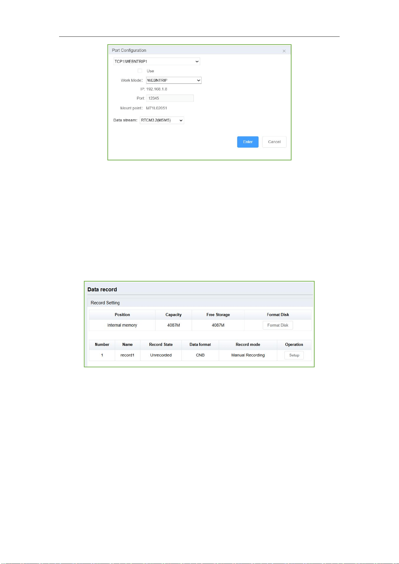
WEBNTRIP:
WEB configuration: setup the IP 192.168.1.8, port 12345, mountpoint M81L0XXXX, and
choose RTCM3.2(MSM5), then check on Use, click Enter, it will transfer data through
WIFI
M8 Laser GNSS Receiver
User Guide
18
3.3.3.2 Data record
This is used to log static data, the data will be saved in the receive, you can download
data via web interface, go to chapter 3.3.3.3 for more information, or you can use USB
cable to connect PC and download static data.
In recording setting interface, you can get following information:
•
Current internal memory capacity and free storage; you can click Format Disk to
format the receiver internal memory;
•
Current record state, data format, record mode.
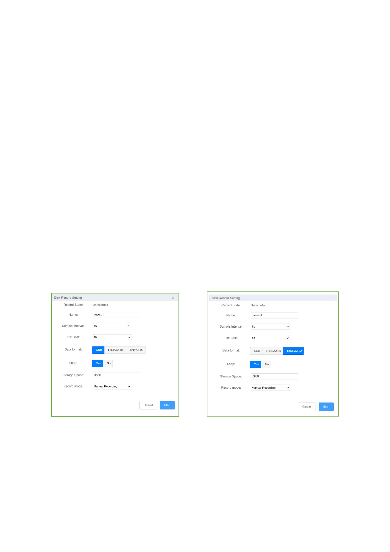
Click Setup to configure the static settings:
• Name: You can choose record1, then the file will be saved in record1 folder.
•
Sample Interval: change the sample interval of observations, the maximum data rate
is 20 Hz, the minimum is one observation per minute, it supports
0.05/0.1/0.2/0.5/1/2/5/15/30/60 S
•
File Split: supports every 15 minutes or 1\2\4\24 hours to save a file, or you can
M8 Laser GNSS Receiver
User Guide
19
choose Manual mode, then it will save a one file when you manually stop the record by
pressing on the static button, or click the Stop button. If you select 24 as file split, it will
create two data files when it occurs to 24 o'clock (UTC Time). One is from start time to
24 o’clock, another is from 0 o’clock to end time.
•
Data format: Supports CNB, RINEX 2.10, RINEX 3.02
•
Loop: When storage is full, Yes means delete earliest data and store continually, No
means stop recording
• Storage Space: Separate storage space in internal memory
•
Record mode: logging data manual recording or auto recording.
•
Auto recording: when you set automatically, it will record static data automatically
when the receiver tracks satellites, and you can stop recording by pressing the static
button on the receiver;
• Manual recording: when you set manually, then it will not record data automatically
when the receiver tracks satellites, need to press the static button on the receiver. Click
Enter to start the recording, and it will save the configuration, you can stop the
recording by pressing the static button or click Stop on the interface.
3.3.3.3 Data Download
• Firstly, select record Name, File type (CNB\Rinex3.02\Rinex2.10) and the date.
•
Then click Get Data, you will see data files.
M8 Laser GNSS Receiver
User Guide
20
• Click Download icon to download the data file you need; or click Delete icon to
delete this file; click Select All, you can select all the data in the current interface,
download and delete them in batches. Rinex files include observations and ephemeris
and not are zip files.
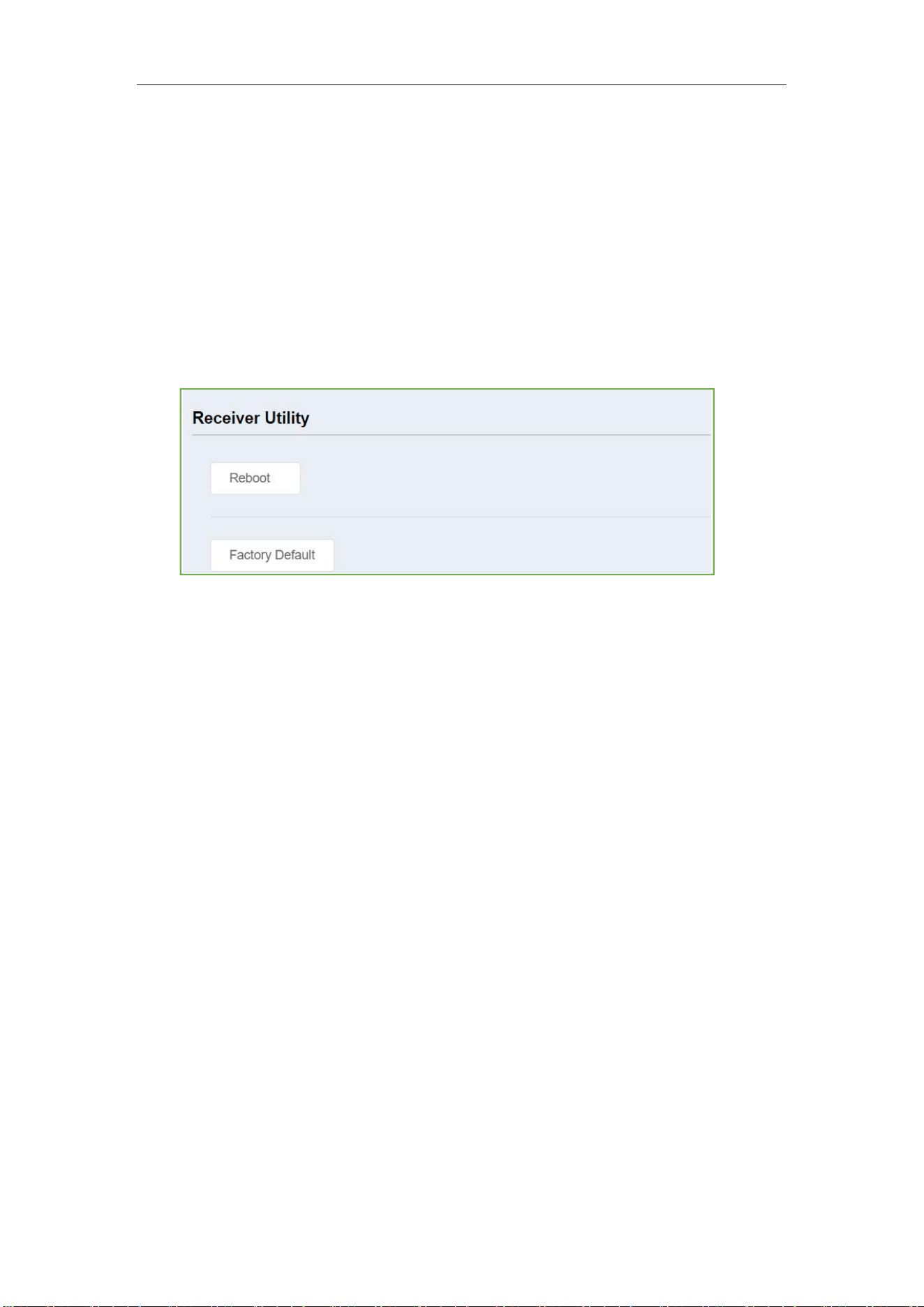
3.3.3.4 Receiver Utility
In this section, you can control M8 remotely, including:
•
Reboot: Restart the receiver
• Factory Default: recover the receiver to factory default setting
M8 Laser GNSS Receiver
User Guide
21
4. Static survey
This chapter describes static survey through M8 receiver and CRU software. For static
survey, you cannot change settings through front panel, you can configure it via
Compass Receiver Utility (CRU): 1) Receiver configuration; 2) check receiver settings
and status; 3) convert data to Rinex format.
4.1 Receiver Configuration
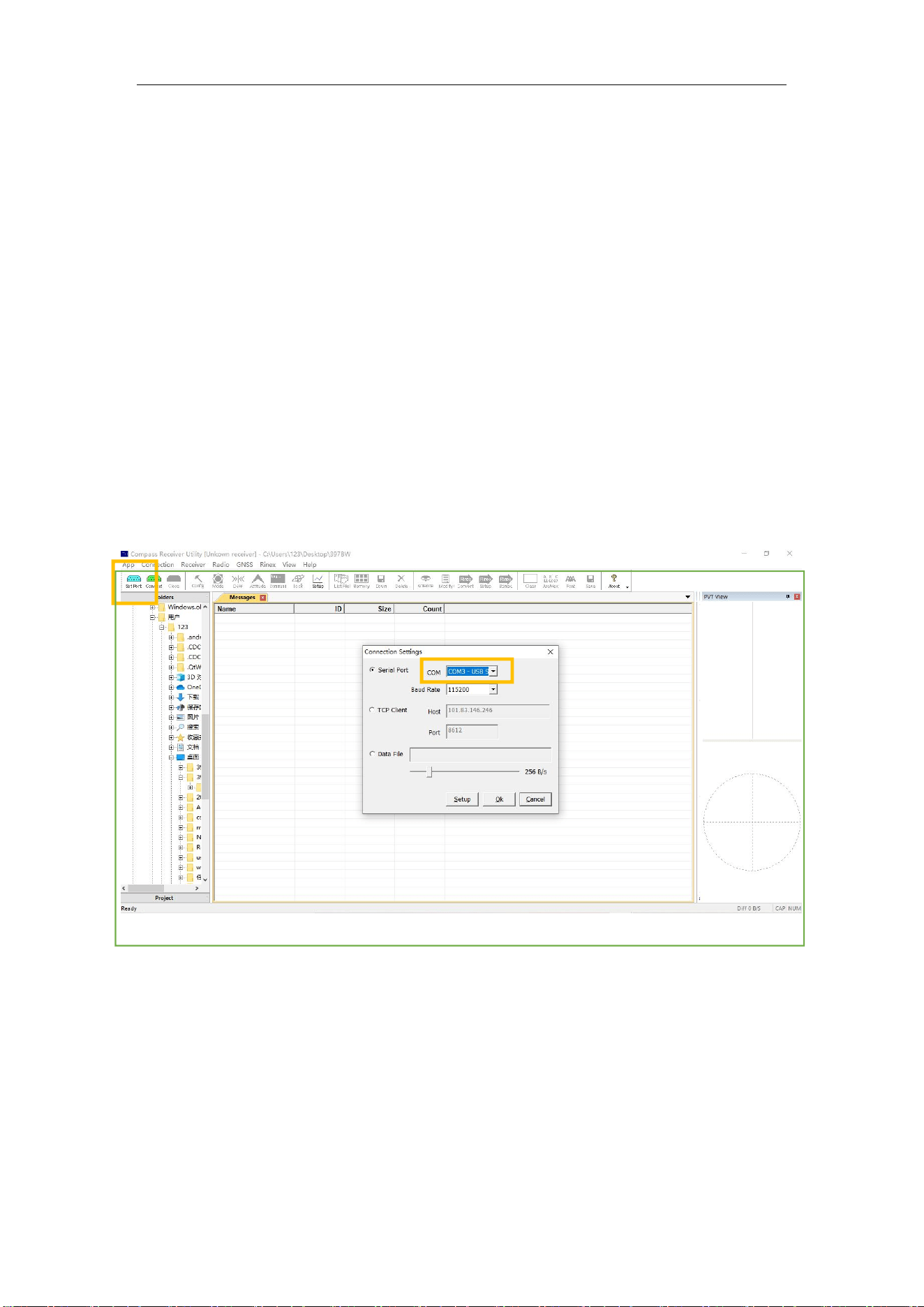
1. Download and install CRU software (ensure the driver is properly installed in your
PC):
2. Put a battery in the M8 receiver and turn it on.
3. Connect the receiver with your PC through type-c cable.
4. Click set port in CRU -> select proper serial port in the serial port option-> enter
proper baud rate -> click Ok to complete receiver connection.
M8 Laser GNSS Receiver
User Guide
22
4.2 Static Data Collection
Static survey is mainly used for the control survey. To reach millimeter accuracy, follow
as below:
• At least 3 GNSS receivers are required to form a stable triangulation network.
•
It is better to set Data Log Session as manual on the known point.
•
Power off the receiver before moving to other observation site.
• To quickly post-process static observation raw data, write down the station name,
receiver SN, antenna height, start and end time for each observation site.
Tip: You can start recording static data in the front panel, it’s convenient for you.
4.3 Static Data Download
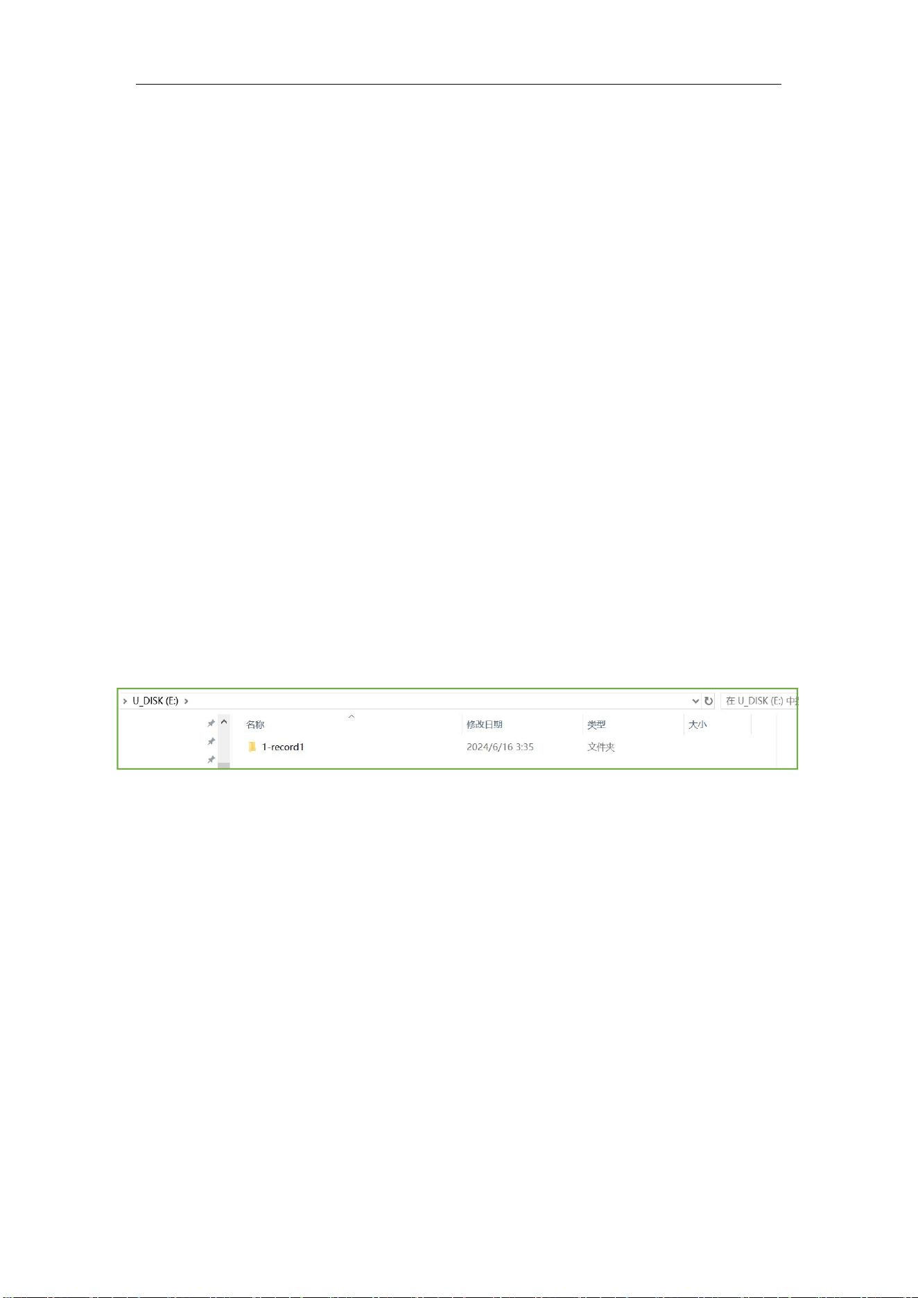
The raw observation data is saved in internal memory of M8 receiver, when connected
with PC via USB cable, the M8 receiver can work as a USB Flash Disk, which means you
can copy or cut static data to PC directly.
Tips:
1. Default memory for M8 receiver is 8GB, and 16GB, 32GB optional.
2. The receiver will stop recording raw data if the internal memory runs out.
4.4 RINEX Convert
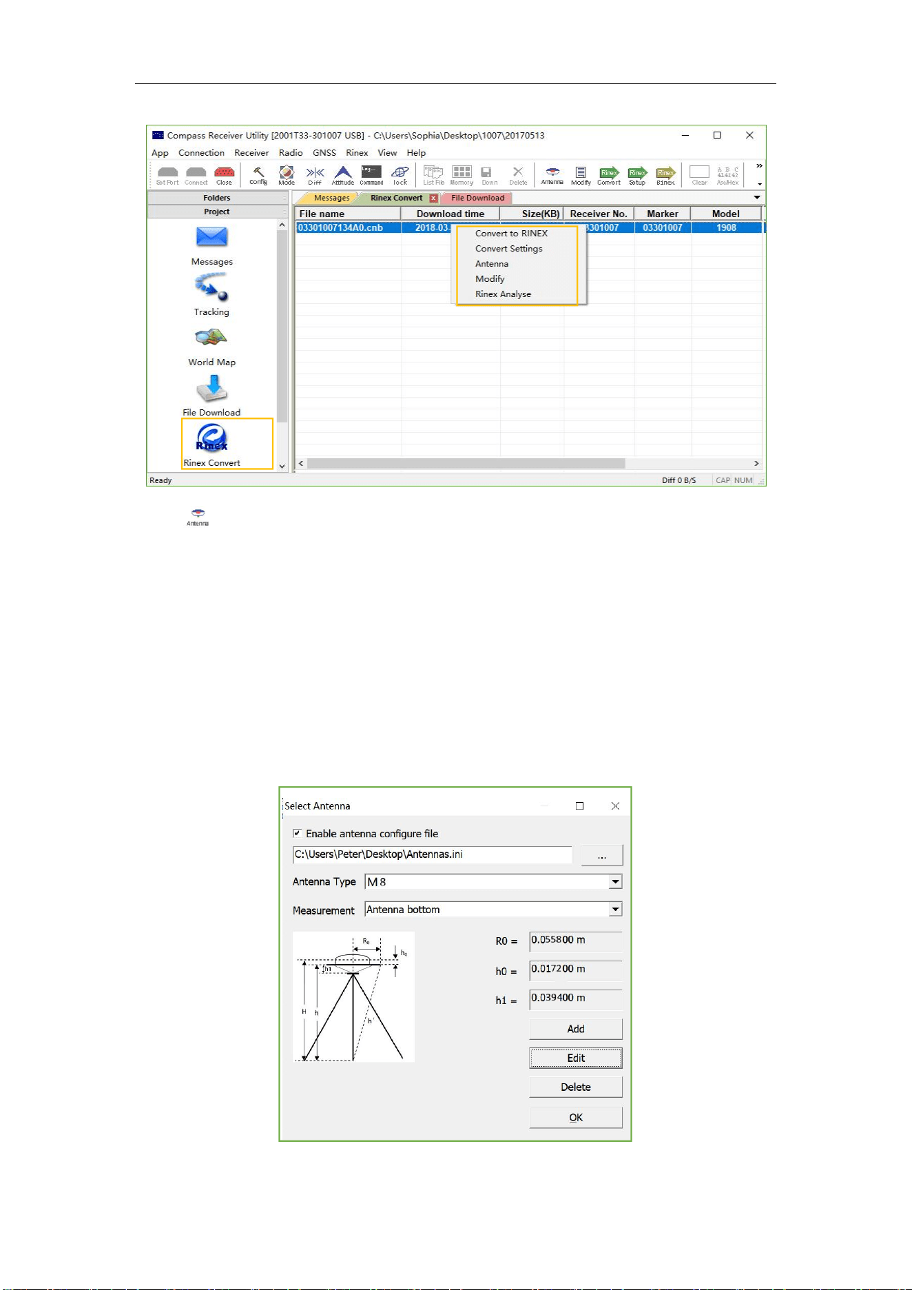
After copy raw observation data to PC, you can convert the data from MaxNav binary
format (*.cnb) to RINEX in CRU software.
1. Start CRU software;
2. Click Folders and select the path of your CNB data;
3. Click Rinex Convert to check all raw data on main window. Right click on the file to
M8 Laser GNSS Receiver
User Guide
23
modify antenna, Convert Settings and Convert to RENIX, or use fast icon in standard bar.
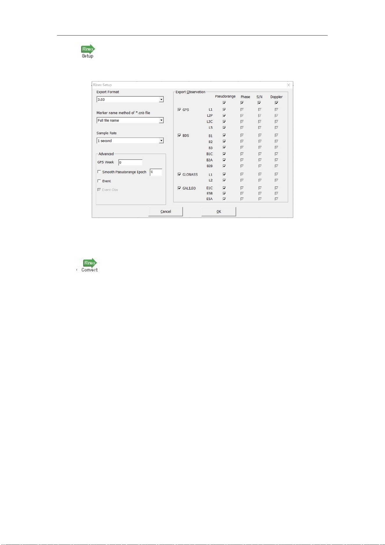
4. Click to select the Antenna Type and Measurement. If you cannot find M8
antenna.
1) Input the value of R0 (horizontal offset from measurement mark to phase center), h0
(vertical offset from measurement mark to phase center) and h1 (vertical offset from
measurement mark to receiver bottom). R0 is 0.062m, h0 is
0.016
m and h1 is 0.054m
respectively for M8 receiver;
2) Or check Enable antenna configure file to select Antennas.ini file to select Antenna
type again. You can also add, edit and delete antenna types based on your requirement.
M8 Laser GNSS Receiver
User Guide
24
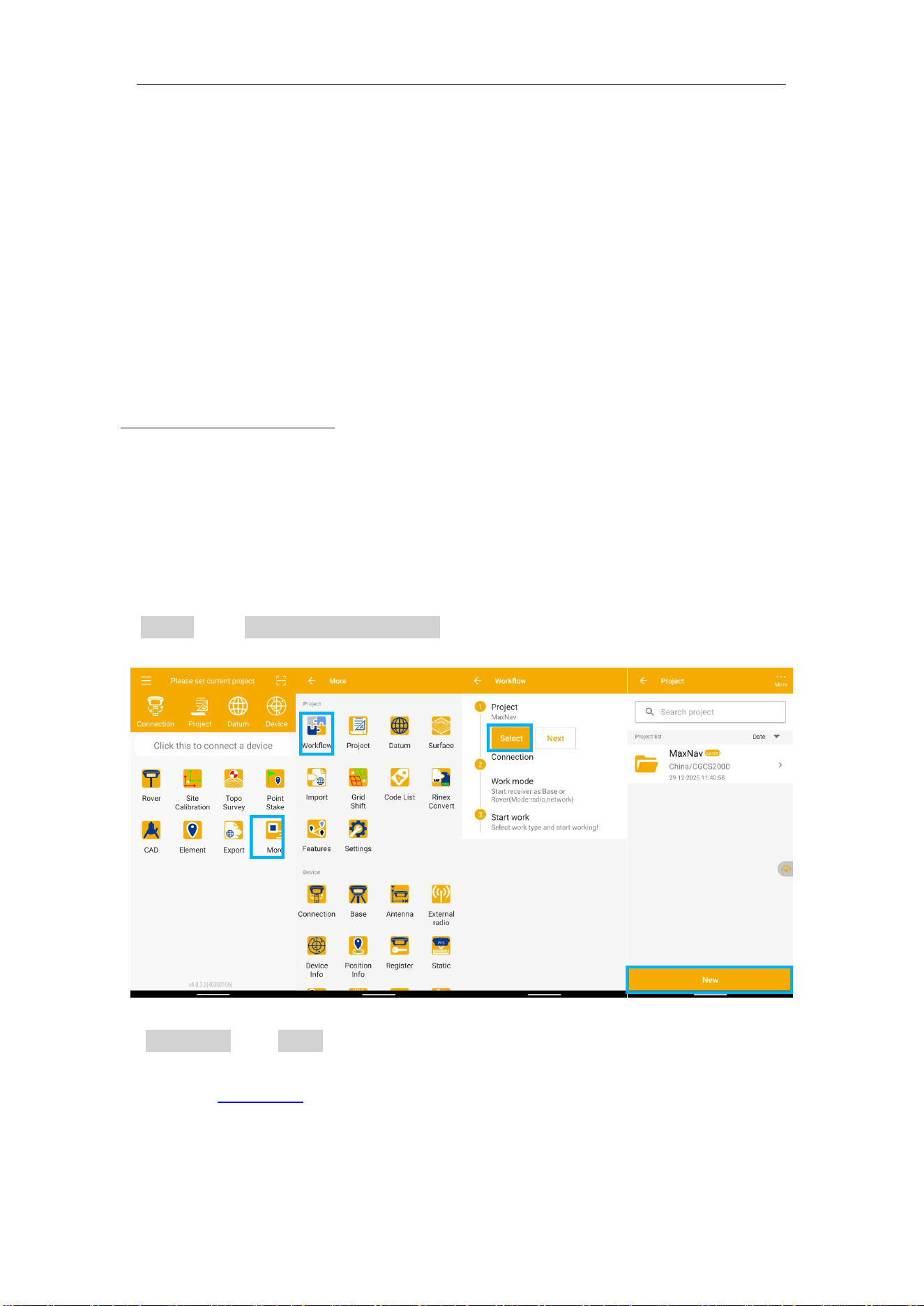
• Click to change Convert Settings, mainly export format and export observation
information.
Tip: In some Post Processing software, the BeiDou observations cannot be processed, you can uncheck
the BeiDou B1,B2,B3 observations.
• Click to Convert to RINEX, the RINEX data will be save in the same path as raw
observation data.
M8 Laser GNSS Receiver
User Guide
25
5. Real-Time Kinematic Survey (RTK)
This chapter introduces how to conduct RTK Survey with Mfield Software, including
software installation, start a new project, receiver connection and RTK working modes
(CORS).
5.1 Installation of Mfield
Mfield is available on Google play, you can download for free and install the software to
MaxNav controller C50.
Also you can download the latest version from our website:
https://www.maxnav.com/
5.2 Wizard function in Mfield
Follow the Wizard, you can quickly learn the general workflow of Mfield , also you can
quick start your survey by this function no matter you are experienced one or new user.
In Project menu, tap Wizard.
1. Project: Click More->Workflow->Select, go into Project interface to create or select a
project. For detailed information, you can refer to chapter 5.3.
2. Connection: Click Select to go into connection interface. Because M8 has one
camera,You can choose connect M8 with Mfield via WiFi, For detailed information, you
can refer to chapter 5.4.
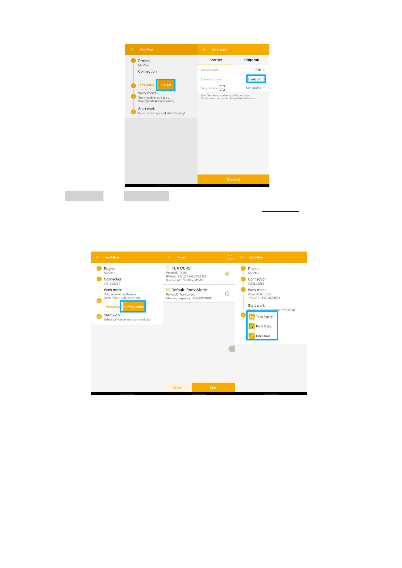
M8 Laser GNSS Receiver
User Guide
26
3. Work mode: Click Configuration to go into Quick Setup interface to start your
receiver as Rover. For detailed information, you can refer from chapter 5.5.
You start your receiver as Rover, then you can start work directly of topo survey or
stakeout
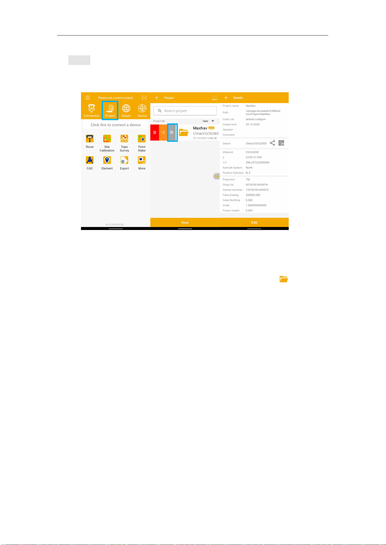
M8 Laser GNSS Receiver
User Guide
27
5.3 Start a New Project
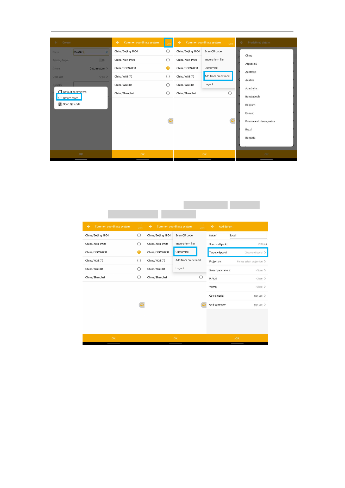
Click Project, you can use the same Datum with last project, choose a datum in store and
scan QR code from other controller to add Datum, even sharing project with cloud.
If you want to start work with receiver, you should select one project with datum
information.
In Project interface, you can click New to add a new project or click k to open the
previous project. It also supports to backup your project file by uploading your Cloud
account, and download from it. If you delete the projects accidently, you can recover
them from Recycle Bin.
Mfield supports to order the project by date and name, in order or reverse order.
If you have added one project, you can click View or click the project name in the main
interface to check the current project details, including Project name, store path, and
datum parameters. Click the QR to share your datum information to others. Besides,
click Edit to change the datum parameters, also, you can change in the Datum interface.
You can select a code list when you create a project, for more information, pls refer to
Chapter 5.3.
To edit datum parameters, Mfield supports three methods: Use last project, Datum store,
Scan QR code.
⚫ Select a Predefined datum: You can select datum directly from the list. Mfield
currently has 49 countries datum and will add more afterwards.
M8 Laser GNSS Receiver
User Guide
28
⚫ Create a User defined datum: If you cannot find datum you want in the list,
follow instructions below to add one: select Target Ellipsoid, Projection for your
datum, and even seven parameters, geoid model based on your request.
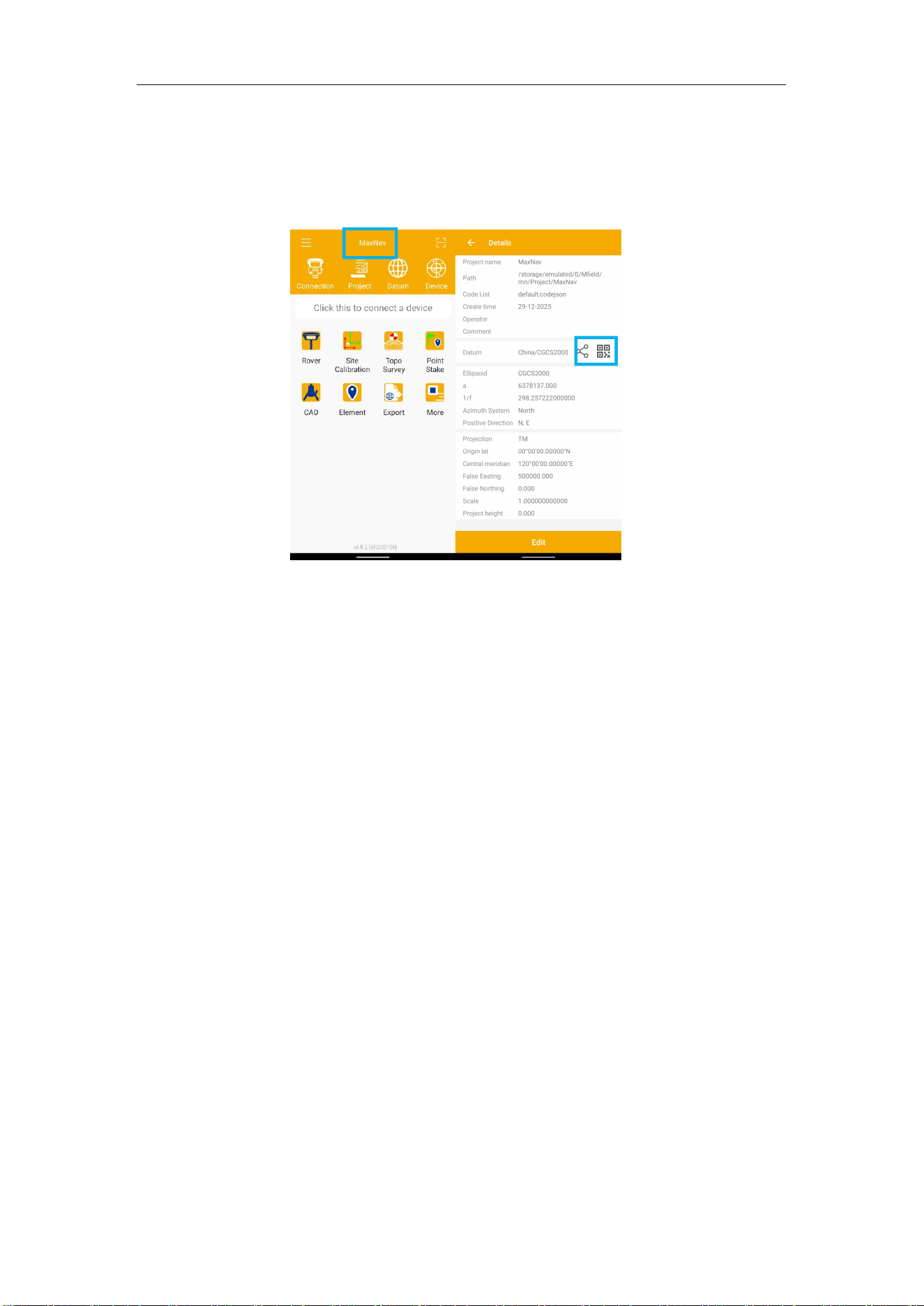
M8 Laser GNSS Receiver
User Guide
29
⚫ Share Datum via QR code.
⚫ After you build a project, press the project name, it will generate a QR code.
Users can use the Scan function in the main interface to access the coordinate
system.
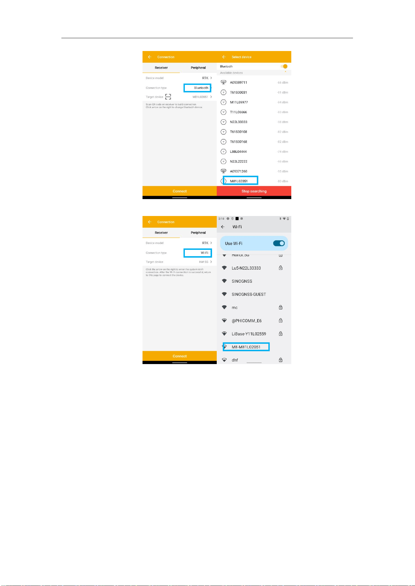
5.4 Connection
To connect Mfield with M8, click More, tap Connection to go into WiFi or Bluetooth
connection interface.
⚫ Make sure device WiFi
or Bluetooth
turned on;
⚫ Click Find device—select SN of your M8 —allow pair. If you use Bluetooth, you
need to pair. If you use WiFi, the password is 12345678.
After connect MaxNav receiver, you can check the device version in Device Info.
M8 Laser GNSS Receiver
User Guide
30
After connected successfully, the top will show the positioning status.
Tip: If you are failed to connect with receiver through Mfield, you can just follow prompt
info to go into the device Bluetooth setting interface to make sure Bluetooth paired
successfully. Sometimes you need restart the receiver or Mfield Software.
M8 Laser GNSS Receiver
User Guide
31
5.5 Work Mode
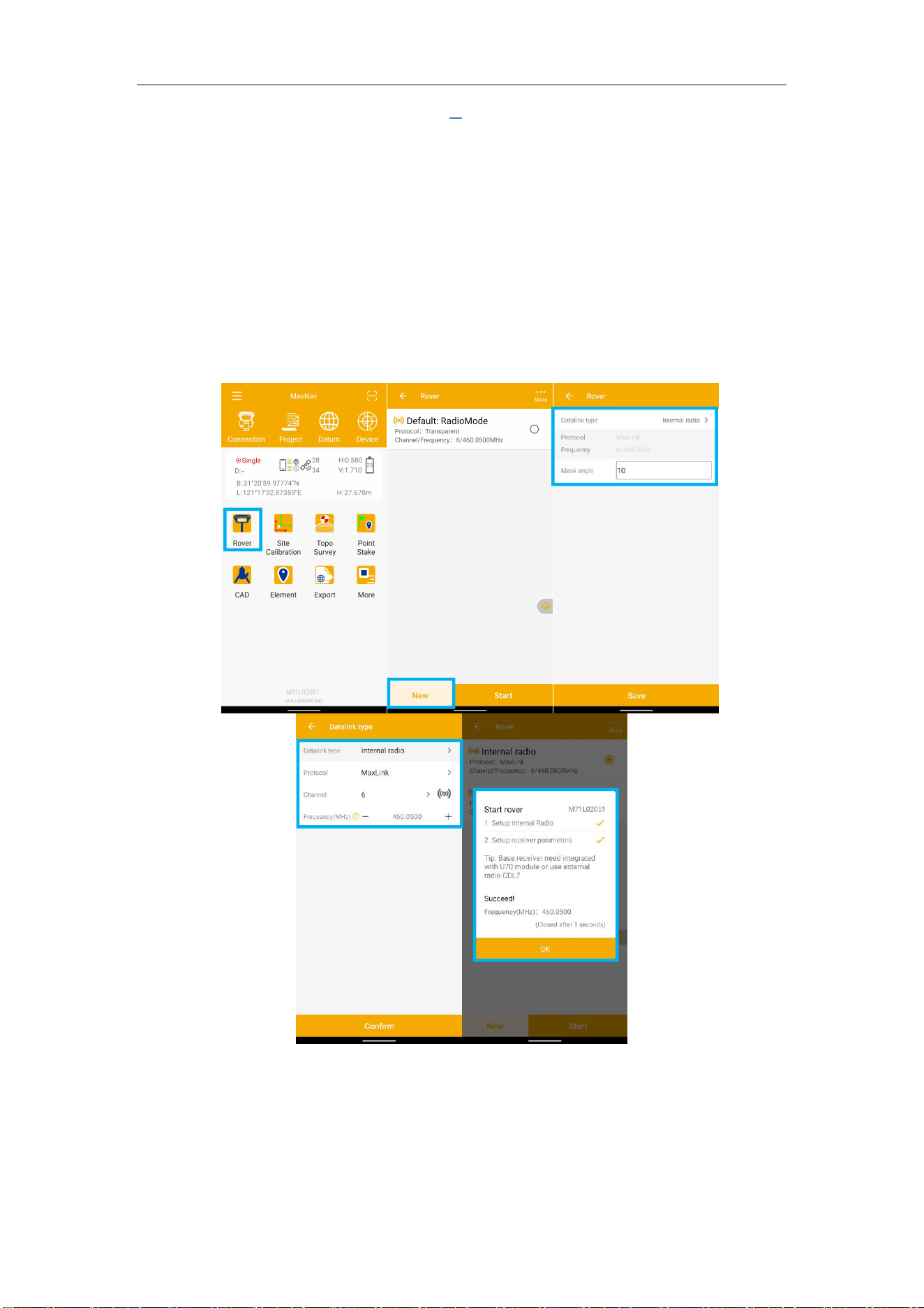
5.5.1 Start Rover with internal radio mode
⚫ Connect Mfield with M8 receiver via WiFi or Bluetooth based on Chapter 5.4.
⚫ Set same protocol and frequency with Base receiver.
⚫ The current status on the bottom will change from Single to Fixed.
M8 Laser GNSS Receiver
User Guide
32
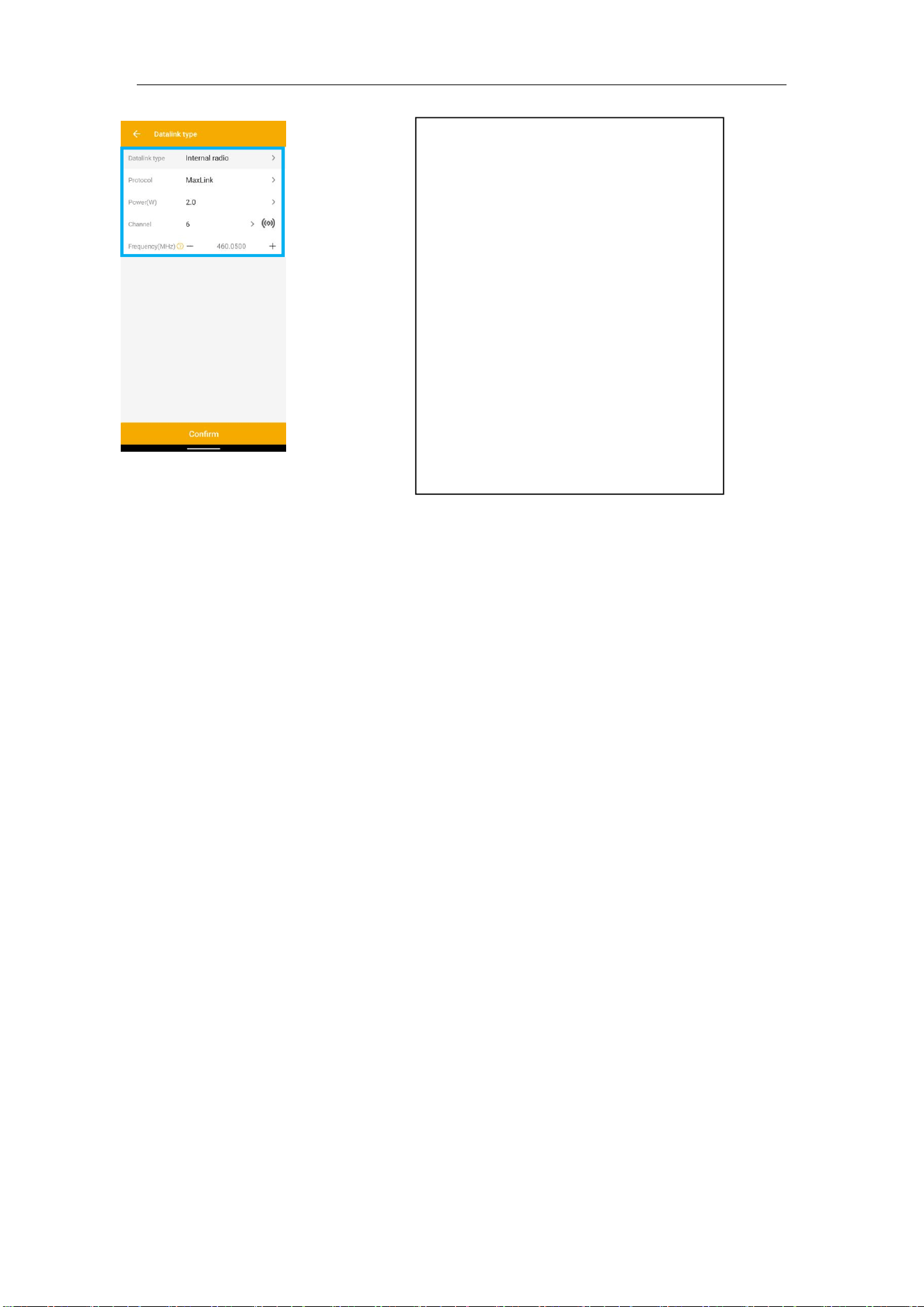
⚫ Protocol and channel: Set
protocol and frequency for the
radio; M8 supports Transparent
/TT450S/South/Mac/Maxlink/
Maxlink+ protocol, It can work with
some other brands’ RTK.
Tips: M8 need to work with latest
OS firmware 1.0.3, and Mfield 4.0.3,
Please confirm with us if you have
problems
M8 Laser GNSS Receiver
User Guide
33
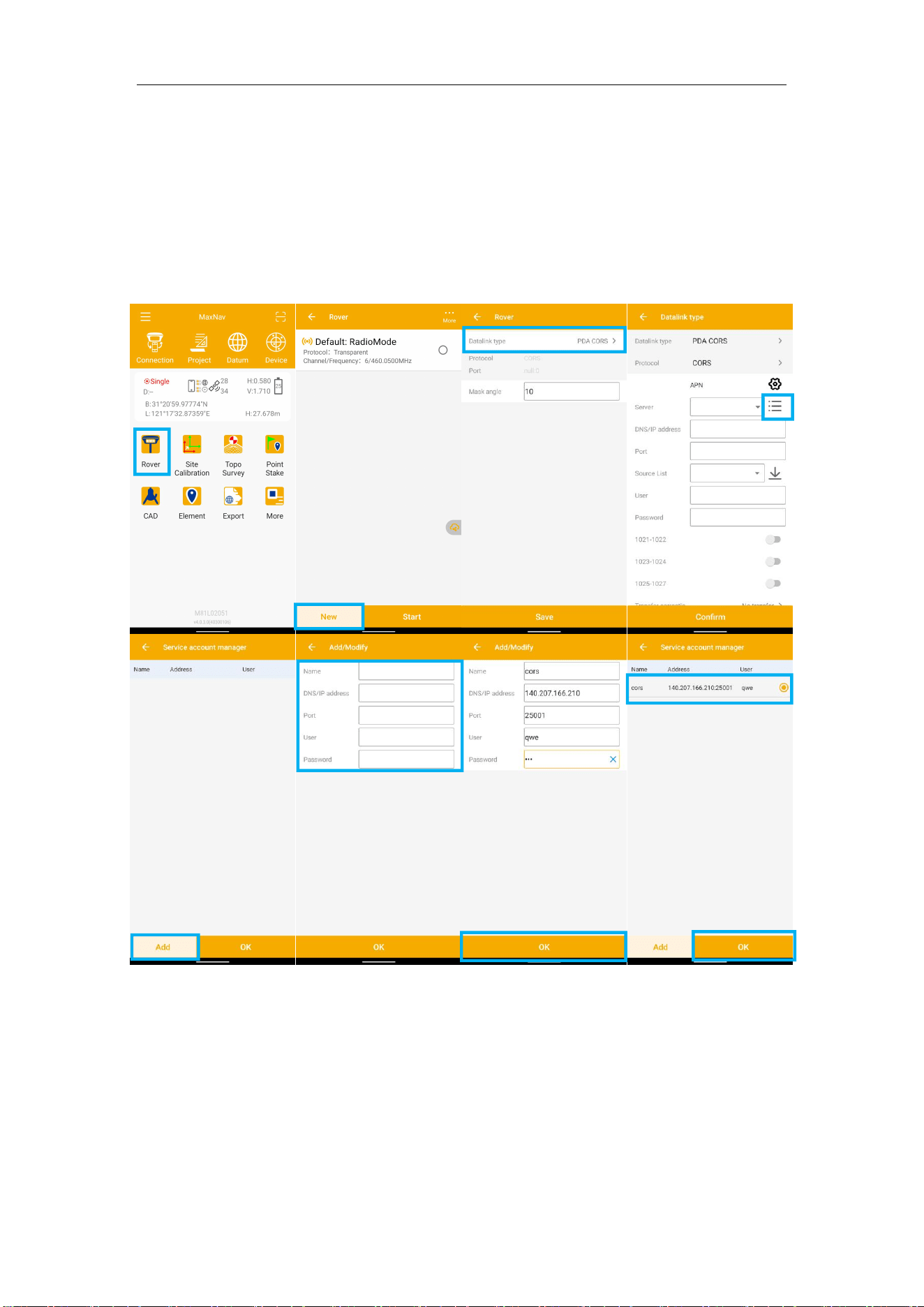
5.5.2 PDA CORS mode
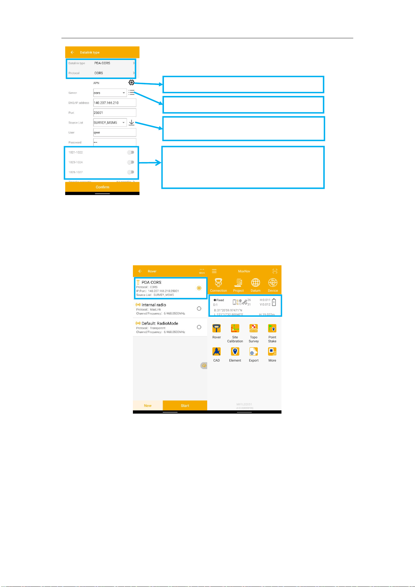
For internal GSM need insert a SIM card to receiver, for PDA CORS need make sure
controller can access to Internet.
You should enter the server IP and Port. In addition, enter User (login name) and
Password to get Source List.
M8 Laser GNSS Receiver
User Guide
34
Enter CORS Name 、DNS/IP address and port -> enter User and password.
Click Source List and select the proper source
After Confirm succeed, the diff LED on receiver will flash, and software can get a
fixed result.
It also provides TCP protocol.
Tip: L-Band is only for PPP function, using PPP function can get the station coordinates
directly, and there is no limit with the distance of stations, the accuracy can be up to 3-5cm.
Press to get source list and select mount point
Press to modify the APN for SIM card
Add your CORS info to list, press to select
1021-1027 message is only available for PDA
CORS mode, the message is used for datum
correction for CORS.
M8 Laser GNSS Receiver
User Guide
35
6. Basic Survey Functions
This section describes the basic survey functions of Mfield, including point
measurement, Topo survey, Auto survey, Area survey, Static, PPK,
staking, site calibration, import and export measured points. You should make sure
your Mfield version supports to connect M8.
6.1 Topo survey
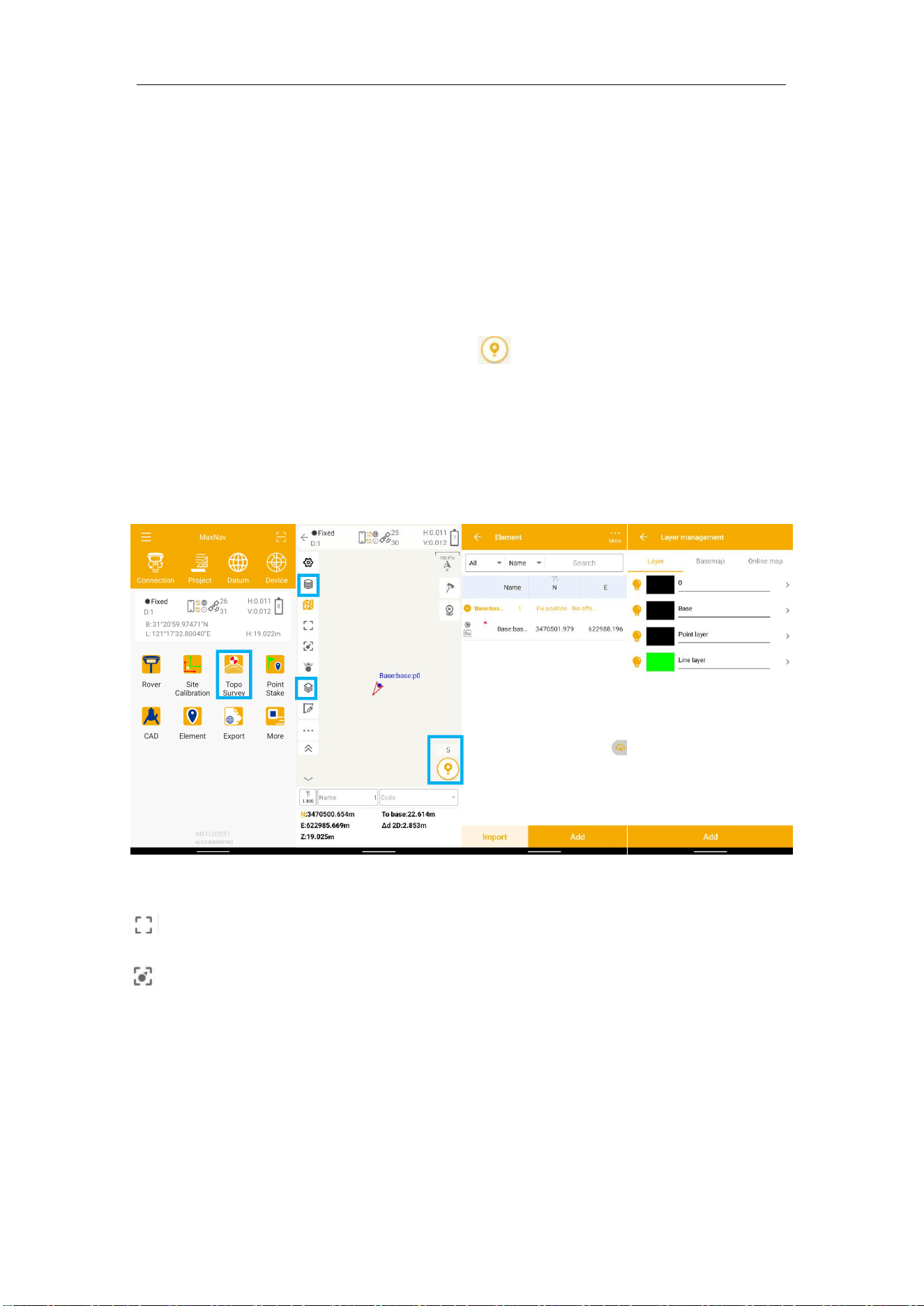
Click Topo Survey-> enter point name, ->click to start or stop collecting data.
⚫ You can quickly change antenna height in the survey interface.
⚫ Tap Elem to check point coordinates.
⚫ Tap Layer to show the layers you want display on map
: Click this to show the whole points on the interface.
: If the arrow is out of sight on the interface, you can click this to locate the receiver
position, then the arrow will be shown on the interface.
M8 Laser GNSS Receiver
User Guide
36
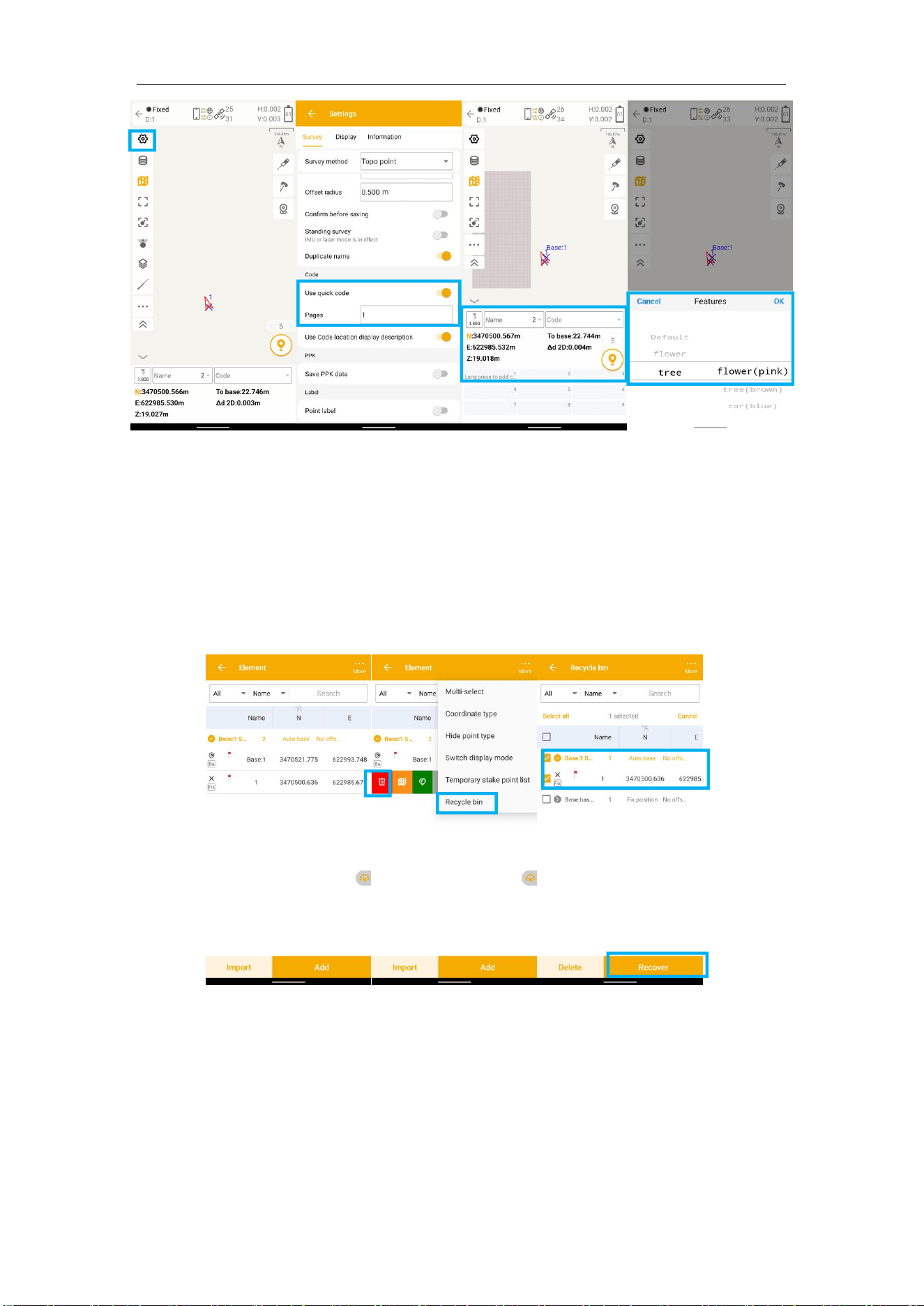
⚫ Fast survey by pressing Code: Tap the code in nine panels, will survey the point
directly.
⚫ Go into code management interface to modify code list, then you can choose code
to use in nine panels.
⚫ Recover deleted points in Recycle Bin.
M8 Laser GNSS Receiver
User Guide
37
6.1.1 Survey settings
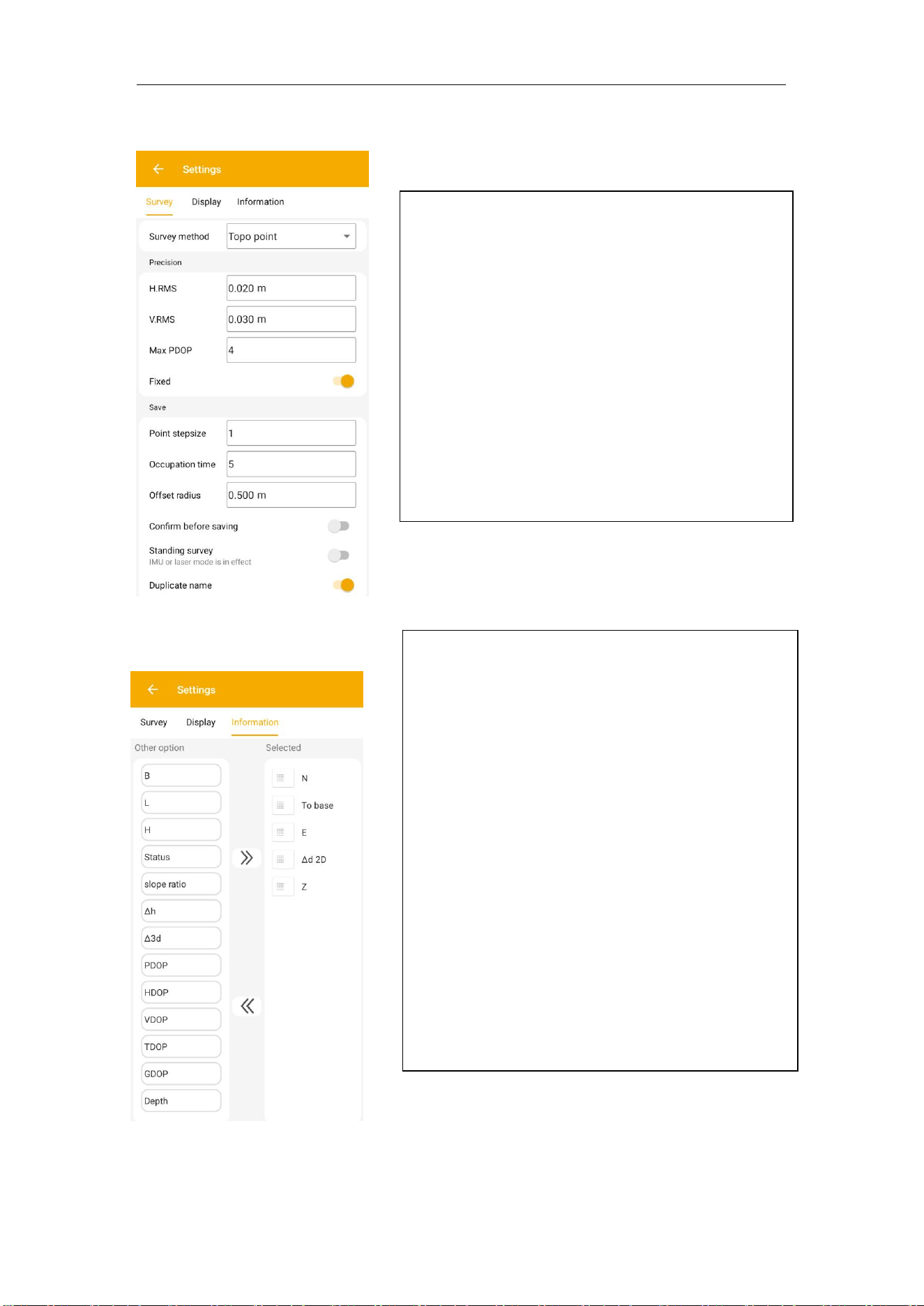
⚫ H.RMS\V.RMS: point accuracy need higher
than the value;
⚫ Fixed: only fixed result can be saved;
⚫ Point stepsize: for point name;
⚫ Occupation time: measure times for one
point;
⚫ Offset radius: point cannot offset bigger
than the value during measure;
⚫ Stake range: show circle when close to target
point;
⚫ Duplicate name: allow point name same;
⚫ Display option: Items which can be shown in the
survey interface, 8 items are the most.
⚫N, E, Z: plane coordinates, displayed in a vertical
column by default
⚫B, L, H: latitude, longitude, ellipsoid height.
⚫Status: receiver RTK solution status, includes
searching, single, float, fixed.
⚫To base: Distance from receiver current position
to the base.
⚫Δd: Distance from receiver current position to last
surveyed point.
⚫Δh: Height difference from current position to last
surveyed point.
M8 Laser GNSS Receiver
User Guide
38
6.1.2 IMU Measurement
Tilt survey option will appear when receiver supports for tilt survey, it is available for
MaxNav Technology M8 laser RTK, use IMU sensor.
According to the IMU sensor, M8 can meet the requirement of high precision
measurement. When the tilts within 60 ° , the built-in sensor based IMU precisely
calculates the actual offset, which accuracy can up to 2.5 cm.
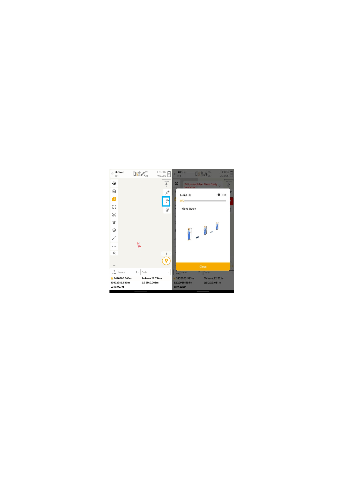
Initialization
If you power off the receiver or freset it, need to initialize again. After open IMU button,
you can follow the guidance in interface to complete it. During operation, make
receiver can search the satellites and get a fixed solution.
Keep the receiver stationary move freely with receiver
In survey interface, you can find the bubble and angle value shows the pole you tilt. For
more accuracy, angle less than 60°will be better.
Tip: Do not shake or rotate the receiver violently, otherwise you need to re-initialize
Jupiter Laser User Guide
39
6.1.3 Laser Measurement
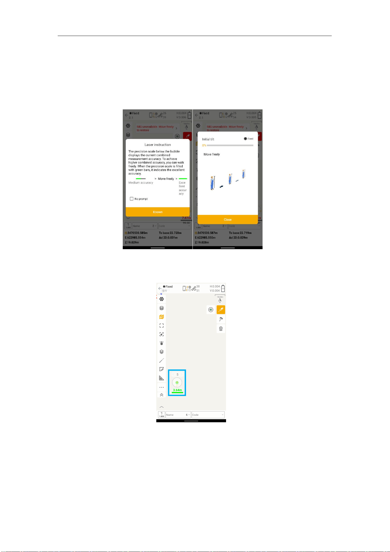
When you first time or long time no use, It may need to you initialize the laser. Go to
topo survey, you will find laser button turn red. Make the receiver get fix and click it
and do the Initialization.
When you finish the Initialization, it will turn green. You can go to point stake to
stake point B out to check laser accuracy.
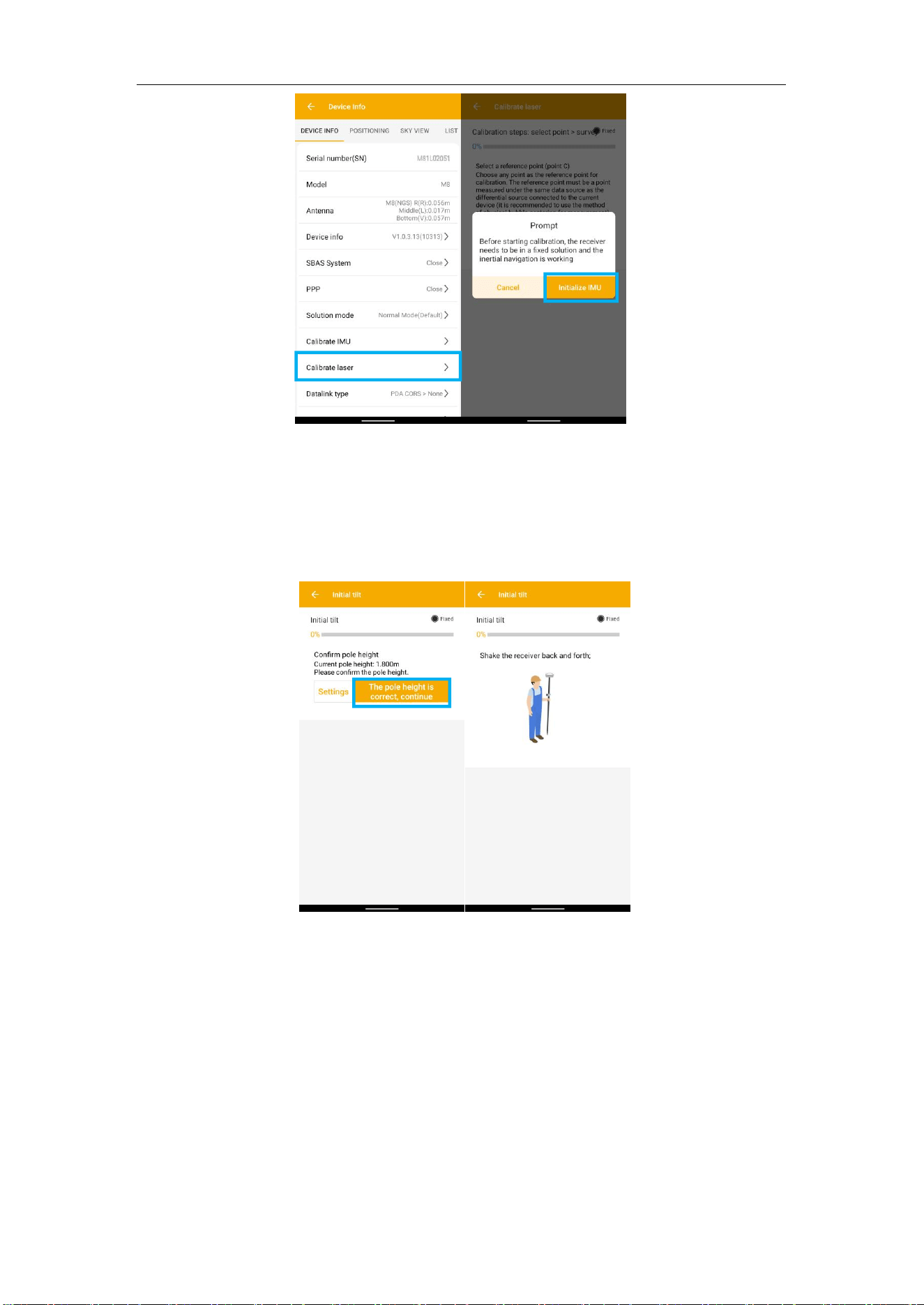
If you feel the accuracy of laser is not good, you need to go to Device >> Device
info >>Calibrate Laser, start tile mode in survey interface and follow the steps to
initialize the IMU. During operation, make receiver can search the satellites and get
a fixed solution.
Jupiter Laser User Guide
40
a) Making sure it gets fixed status
b) Because laser measurement is based on IMU module, you need to initialize IMU
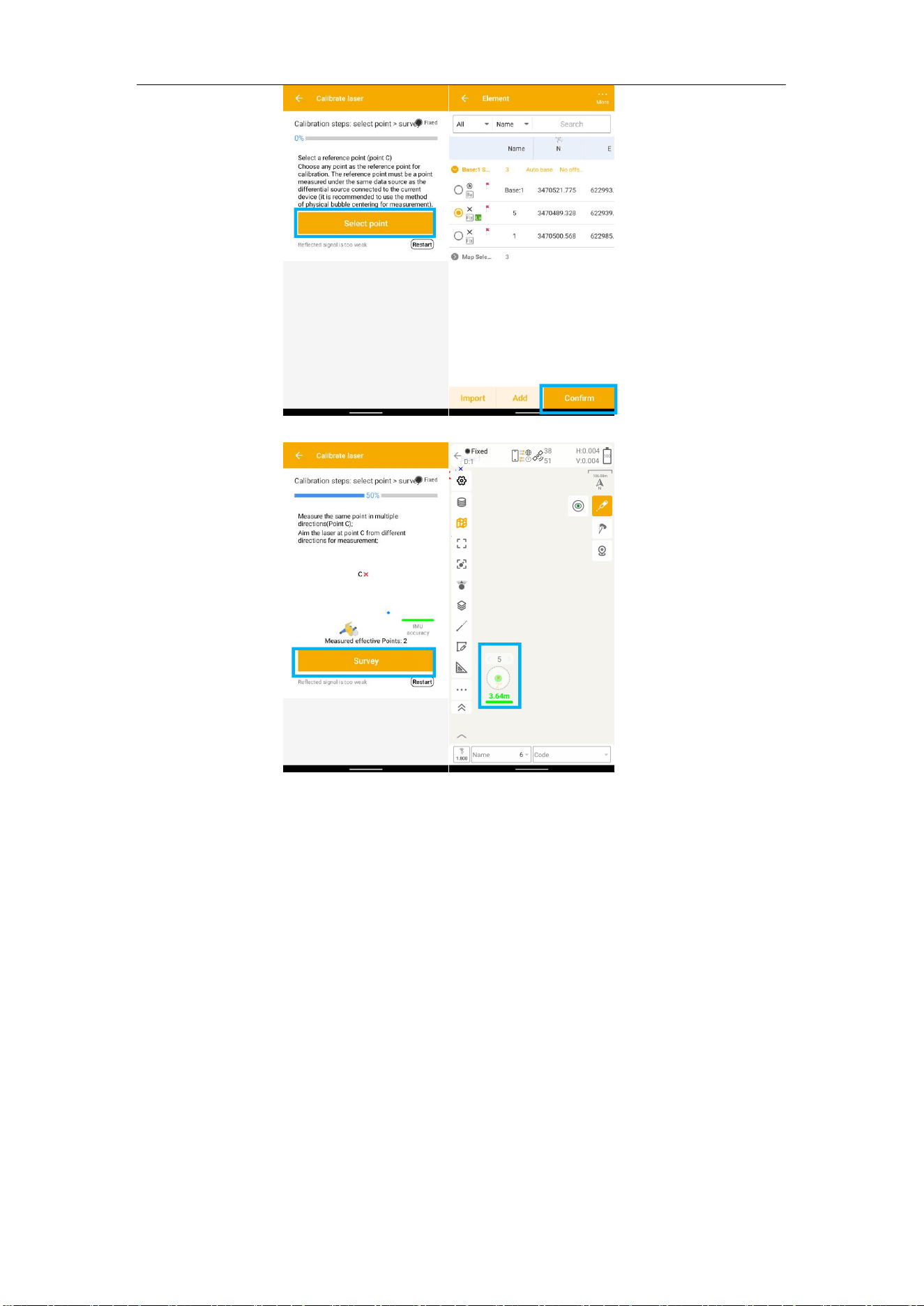
first, shake the receiver back and forth and finish IMU initialization.
c)
Then choose a base point B, handle the Laser receiver to measure the same
point B 5 times from different directions. You’d better do laser initialization within 3
meters to decrease laser offset.
Jupiter Laser User Guide
41
d) When you finish laser initialization, you can go to point stake to stake point B out to
check laser accuracy.
In survey interface, you can find the bubble and angle value shows the pole you tilt, also
laser distance. For more accuracy, angle should less than 60°, it will be better. And the
laser icon will turn green, it means laser is ready to work.
Tip: Do not shake or rotate the receiver violently, otherwise you need to re-initialize IMU.
6.1.4 Visual Measurement
When you finish IMU and laser calibration, you can click camera button to start visual
measurement. Camera can be switched on to help during measurement.
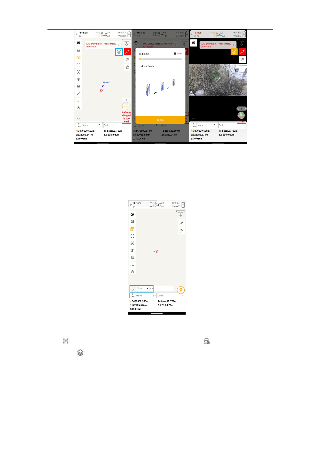
M8 Laser GNSS Receiver User Guide
42
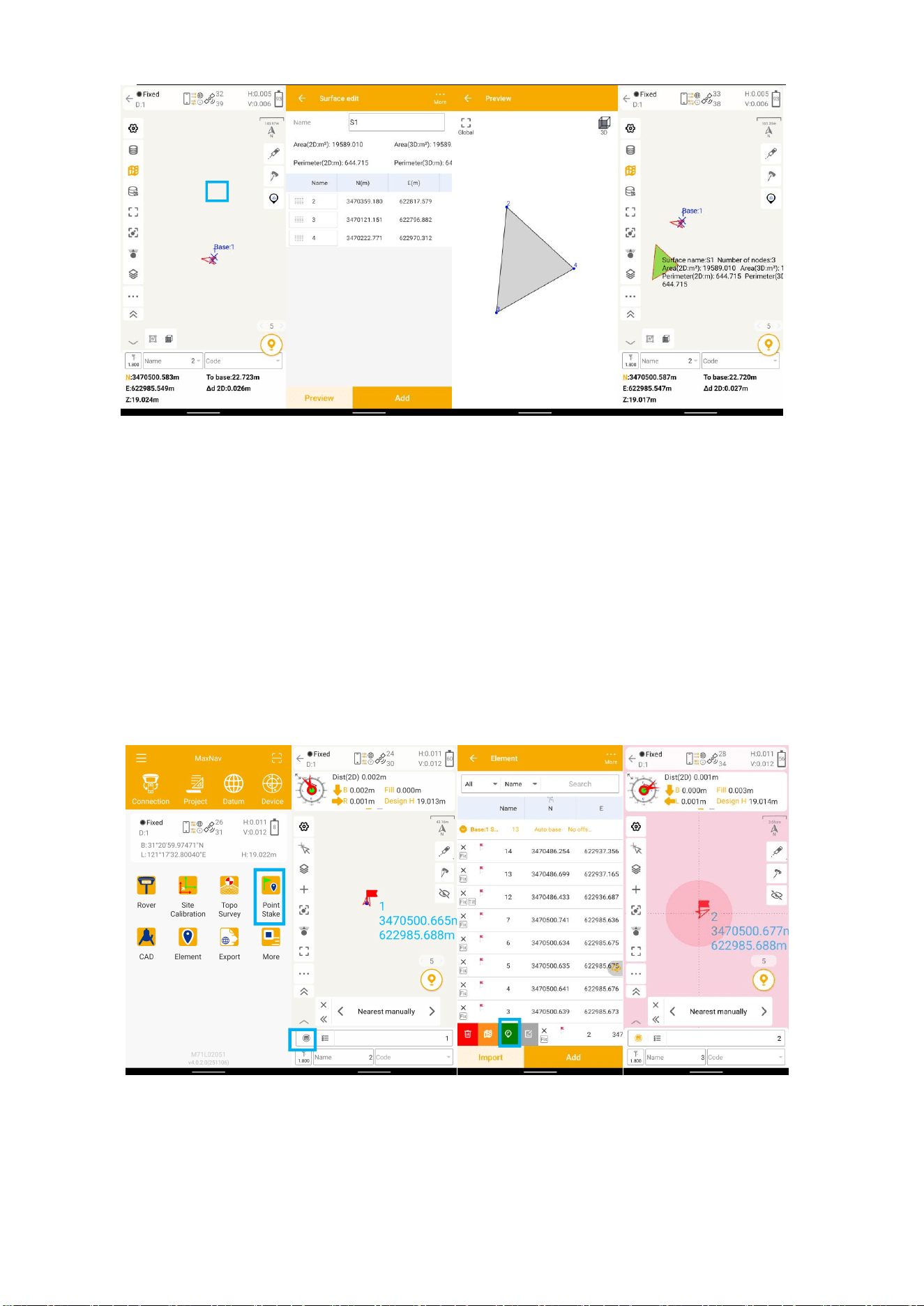
6.2 Auto survey/Area survey
For Auto survey, it supports automatic and continuous survey according to Time or
Distance.
For Area survey, it can compute area directly after getting points.
Press , it will show the coordinate information, press , it will show the area
result, press , it will show the shape on map.
M8 Laser GNSS Receiver User Guide
43
6.3 Stake Points/Lines
6.3.1 Stakeout Points
Go into Stake point interface, click to choose a point and tap Stake. Mfield provides a
navigation map when staking point. If you are close to the target point enough, it will
alarm you based on the alarm range you set.
Various navigation info choices
Tip: Mfield supports to select the point on the screen directly, including the surveyed points
and points from the background layer, when you click the point on the map, it will change to
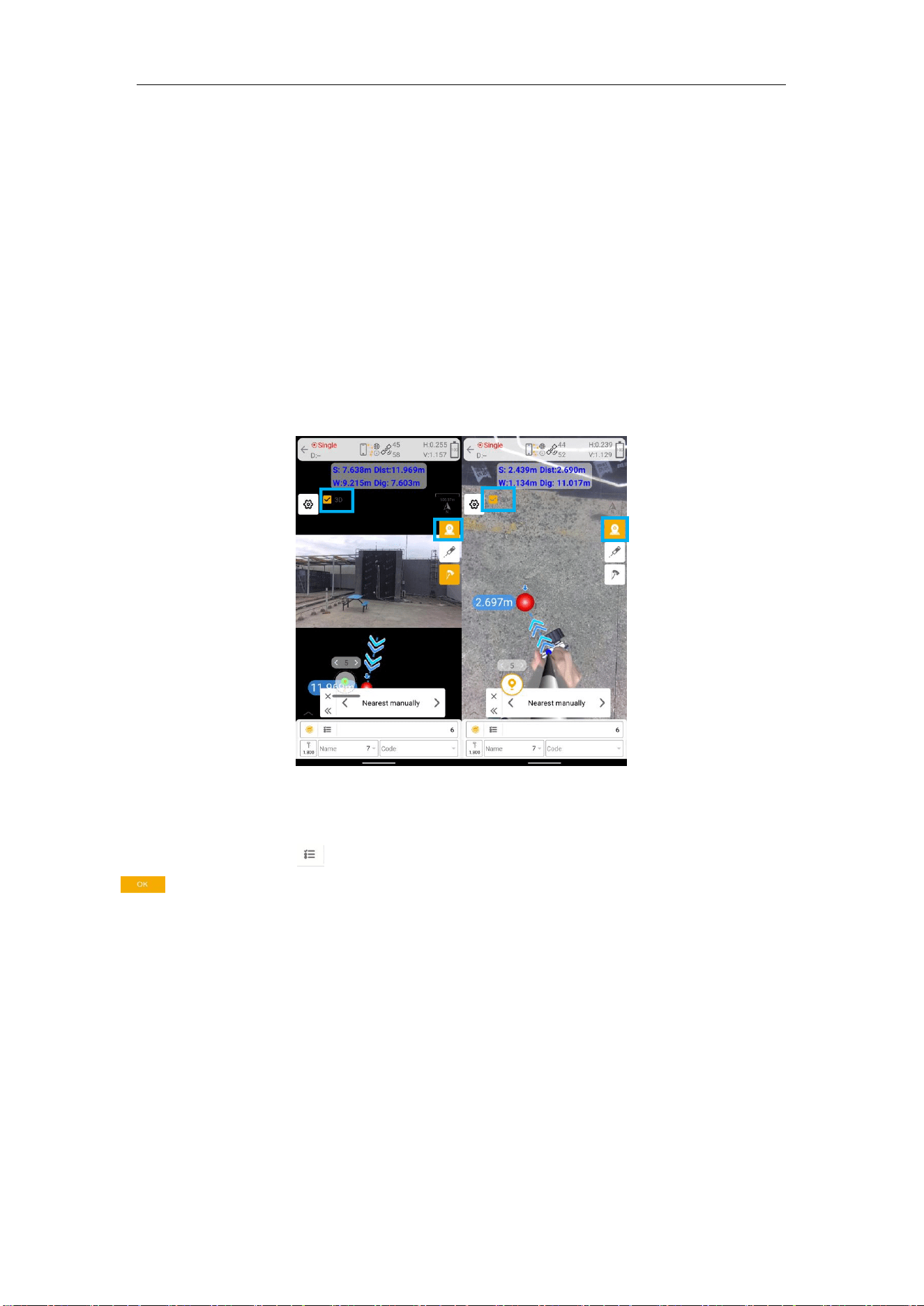
M8 Laser GNSS Receiver User Guide
44
this point automatically, so you can stake it. For the points selected from background layer,
they will be saved to the Element as the Map Selected Point type
Tip: keep your receiver vertical to the ground.
In the IMU staking, you can open IMU function, and don’t need to keep the receiver
vertical to the ground, and the tilt angle supports maximum to 60 degrees.
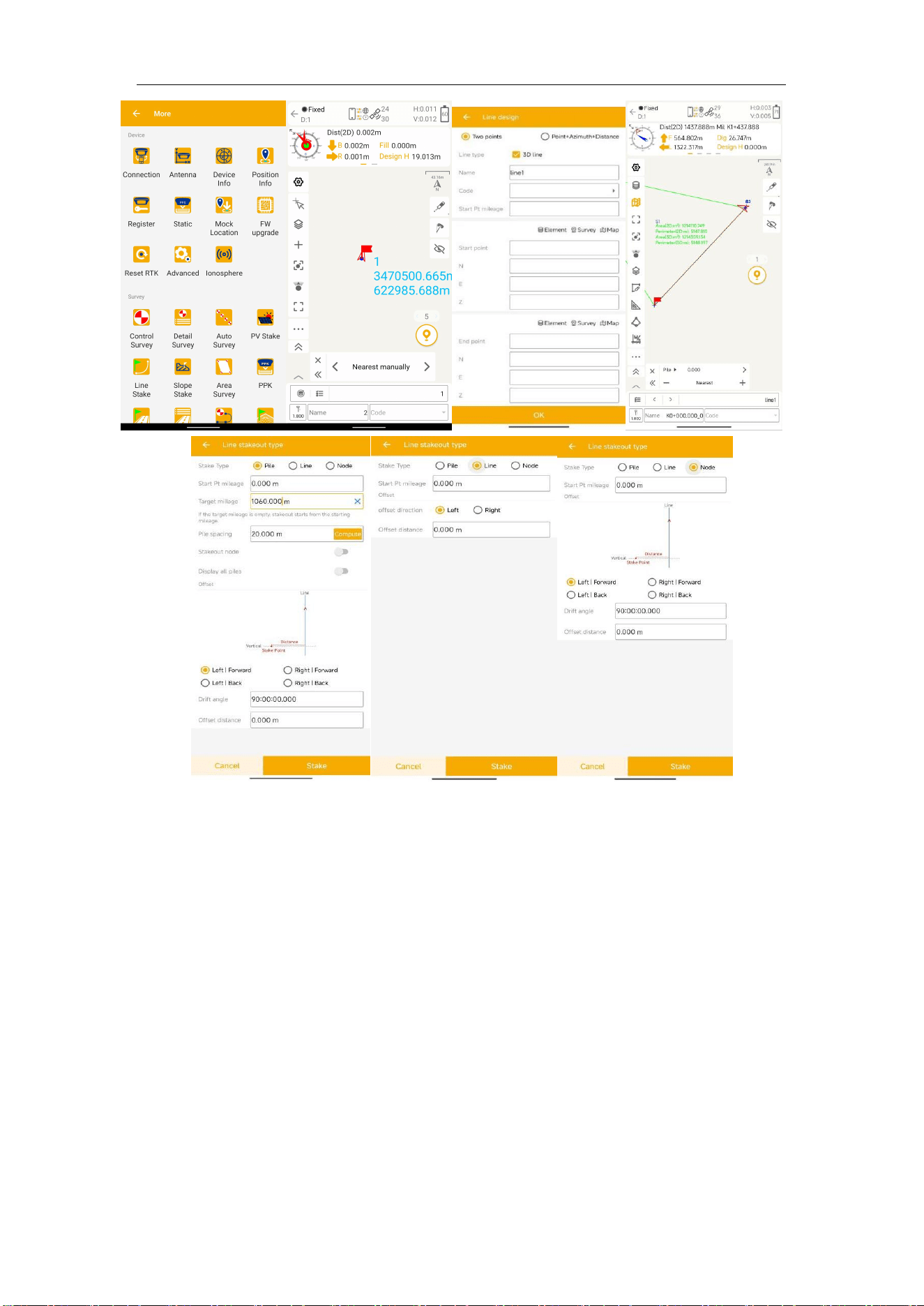
6.3.2 Visual Stakeout
Visual Stake: Connect the M8 and click on the Visual icon to enter visual stake mode. It
support 2D/3D stake. And it will switch bottom camera according to the distance to target
coordinate.
6.3.3 Stake line
For staking lines, click -> add line (Two points or Point + Azimuth + Distance) -> click
-> Choose one line and click Stake. The default method to stake is ‘To line’, press method
to choose a method you want.
M8 Laser GNSS Receiver User Guide
45
7. CAD
In Mfield , we can import CAD file to do survey and stake out work.
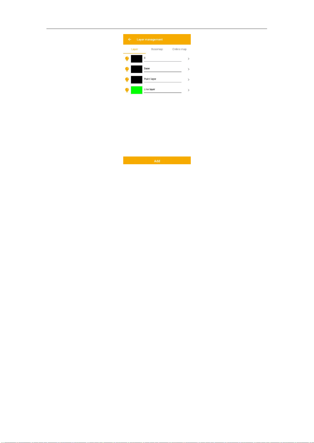
Survey layer:Modify the colour and font size of measured points, release points, map
points, visible status of the input points layer, point symbols, point names, elevation and
code labels in the measurement layer.
M8 Laser GNSS Receiver User Guide
46
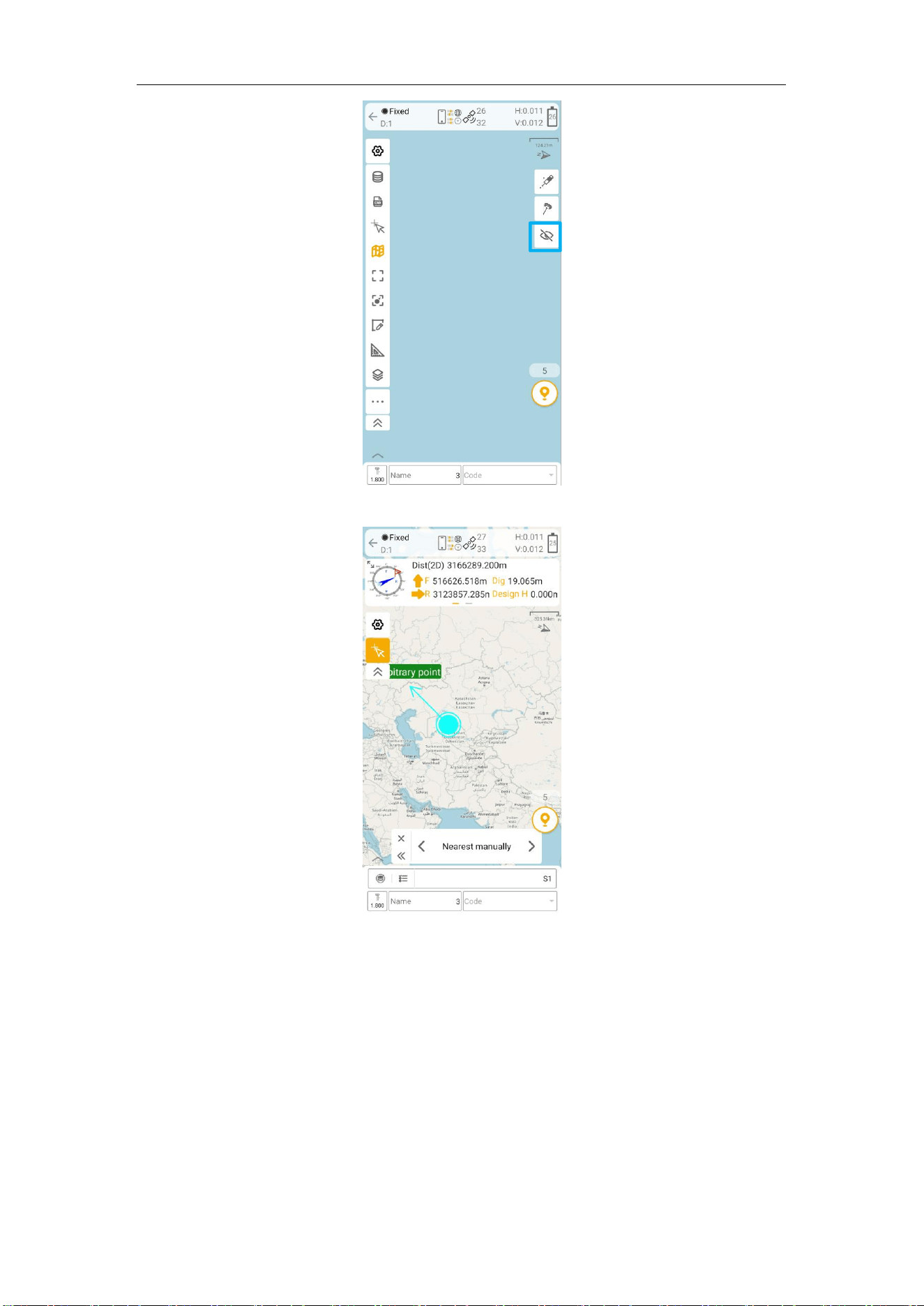
Global: All elements on the diagram are centred.
Center: Click to turn on real-time centering, and the current position is centred in the
middle of the CAD interface.
Follow: Click to turn on the view mode, the CAD drawing orientation changes according to
the handbook orientation.
Settings: Go to Setup Options for Measurement, Sampling, Road, PPK, CAD, and
Information Fields.
Elem: Access to the point library to view measured point information.
Invisible point: There are two modes: visible point mode and hidden point mode. In
visible point mode, all the points in the CAD interface will be displayed, while in hidden
point mode, all the points in the CAD interface will not be displayed.
M8 Laser GNSS Receiver User Guide
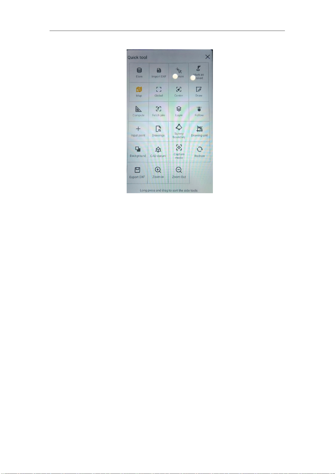
47
Capture:Click the Snap button to display the type of point currently being snapped.
Fetch: Extract feature points from CAD drawings, providing: points, centers, nodes.
Vision: After connecting the vision receiver and the CAD enters the release mode, after
selecting the release target on the CAD, the vision image is switched on and the virtual
points are displayed on the image.
CAD function support measure and stakeout.
Stake points: Use arrow to select points
Measure point:Click measure icon to save current coordinate
M8 Laser GNSS Receiver User Guide
48
7.1 CAD Menu
Background: Edit background color, supports white, black, gray, black is by default, after
you change the color, it will not change when you restart the software or switch project;
CAD Datum: In most cases, the user uses the world coordinate system by default. If the
user coordinate system is set, for example, for the convenience of drawing, the
coordinate system is moved to the plan view of an object. In this case, the user should
select User coordinate system in Mfield.
Capture mode: After you check on these items, when the selection tool approached you
can capture them easily.
Redraw: When the CAD file is not refreshed at the real time, you can click Redraw to
refresh file.
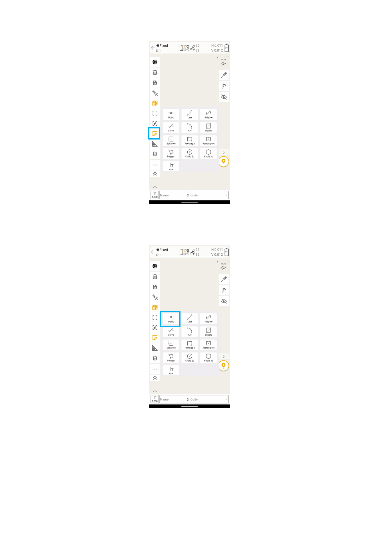
7.2 CAD Drawing
M8 Laser GNSS Receiver User Guide
49
7.2.1 Point
Points can be drawn by clicking on the map, selecting points with the Capture tool, or
selecting points from Element, and entering the point name.
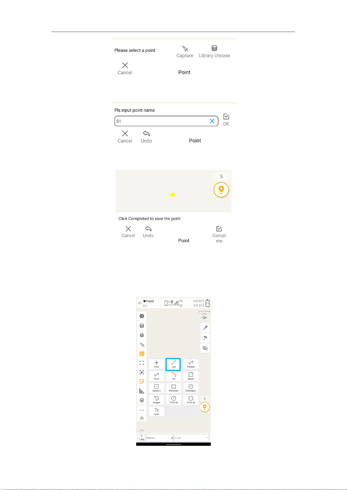
The drawing steps are as follows:
1) You can select points by clicking on the map, selecting points with the Capture tool, or
selecting points from Element. The selected points will be displayed in yellow. Click Cancel
can exit the point drawing operation.
M8 Laser GNSS Receiver User Guide
50
2) The bottom prompts "Pls input point name". Enter the name of the drawing point.
Click Undo to return to the previous step.
3) Click OK, a red point name will appear on the selected point, and the bottom of the
interface will prompt "Click Completed to save the point".
4) Click Completed to complete the point drawing operation.
7.2.2 Line
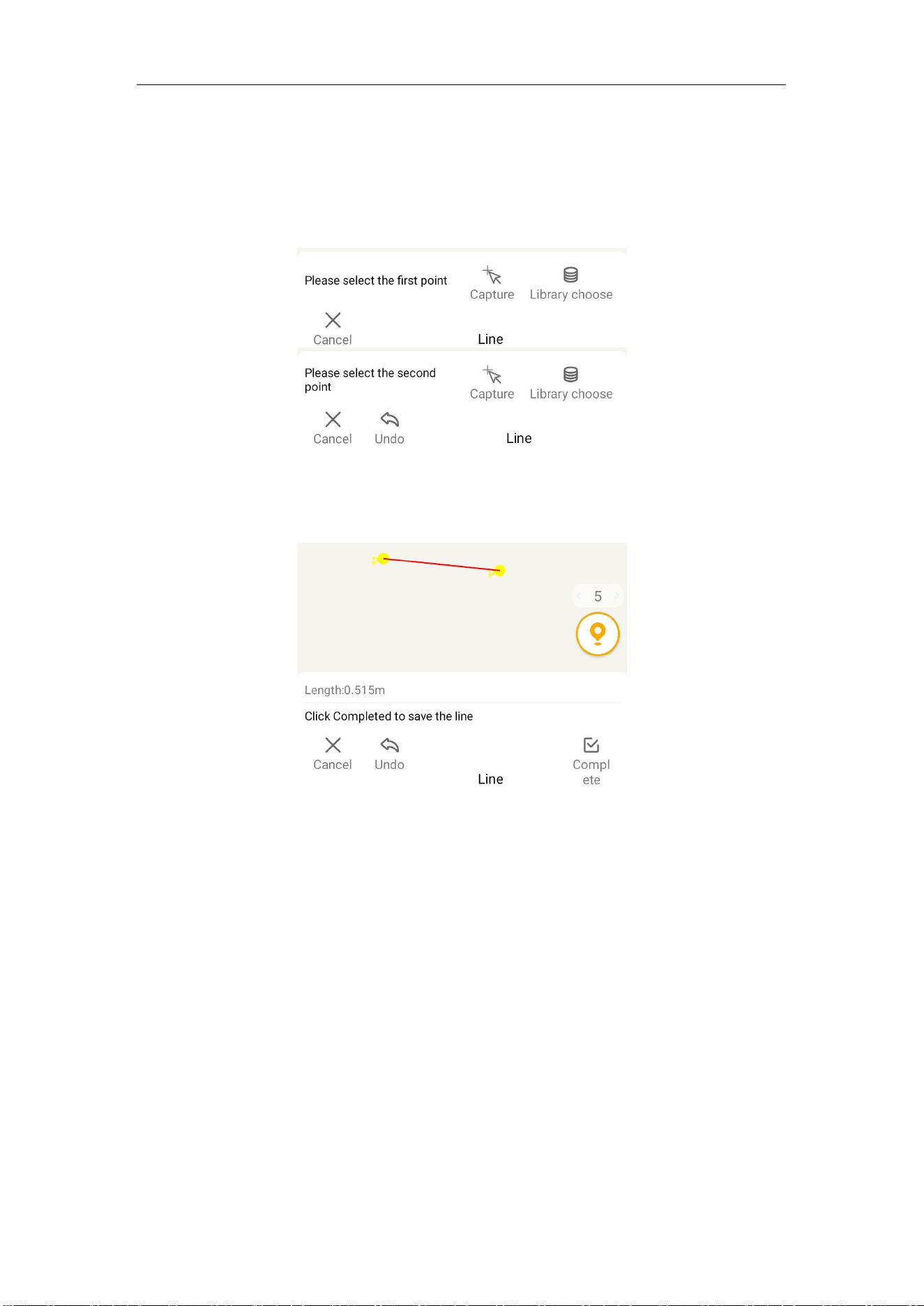
You can select two points by clicking on the map, selecting 2 points with the Capture tool,
or selecting 2 points from Element, and automatically connect them to draw a line.
M8 Laser GNSS Receiver User Guide
51
The drawing steps are as follows:
1) Select the first point by clicking on the map, selecting points with the Capture tool, or
selecting points from Element. The selected point will be displayed in yellow and will not
be saved to Element. You can click Cancel, which will exit the drawing mode. Clicking
Undo will cancel the selected point.
2) After completing the first point, you will be prompted to select the second point, which
is the same as the first point. After completing the point selection, you will be prompted
below to click Completed to save the line.
3) After clicking Completed, the line is successfully created.
7.2.3 Polyline
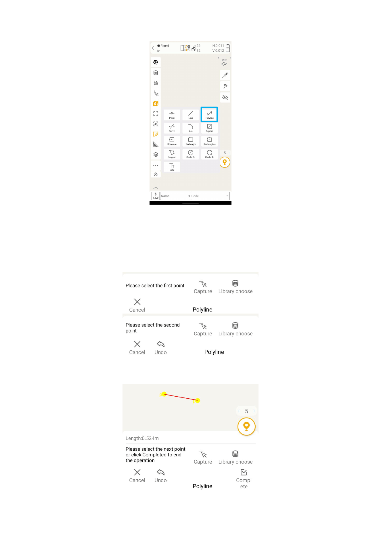
You can select multiple points by clicking on the map, selecting points with the Capture
tool, or selecting points from Element. They will be automatically connected into polyline
in the order of selection.
M8 Laser GNSS Receiver User Guide
52
The drawing steps are as follows:
1) Select the first point by clicking on the map, selecting points with the Capture tool, or
selecting points from Element. The selected point will be displayed in yellow and will not
be saved to Element. You can click Cancel, which will exit the drawing mode. Clicking
Undo will cancel the selected point.
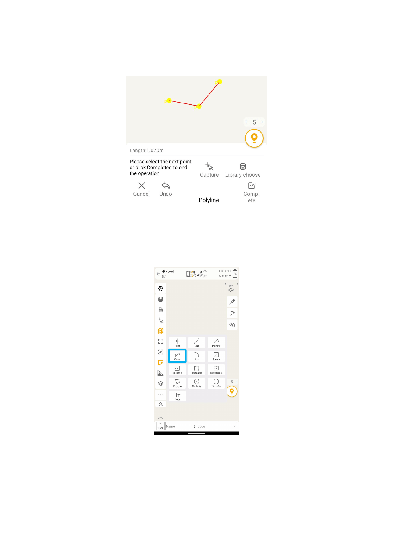
2) After completing the first point, you will be prompted to select the second point, which
is the same as the first point and will automatically form a connection with the first point.
M8 Laser GNSS Receiver User Guide
53
3) After completing the selection of the second point, you will be prompted below to
select the next point or click Completed. You can continue to select points or click
Completed to save the polyline.
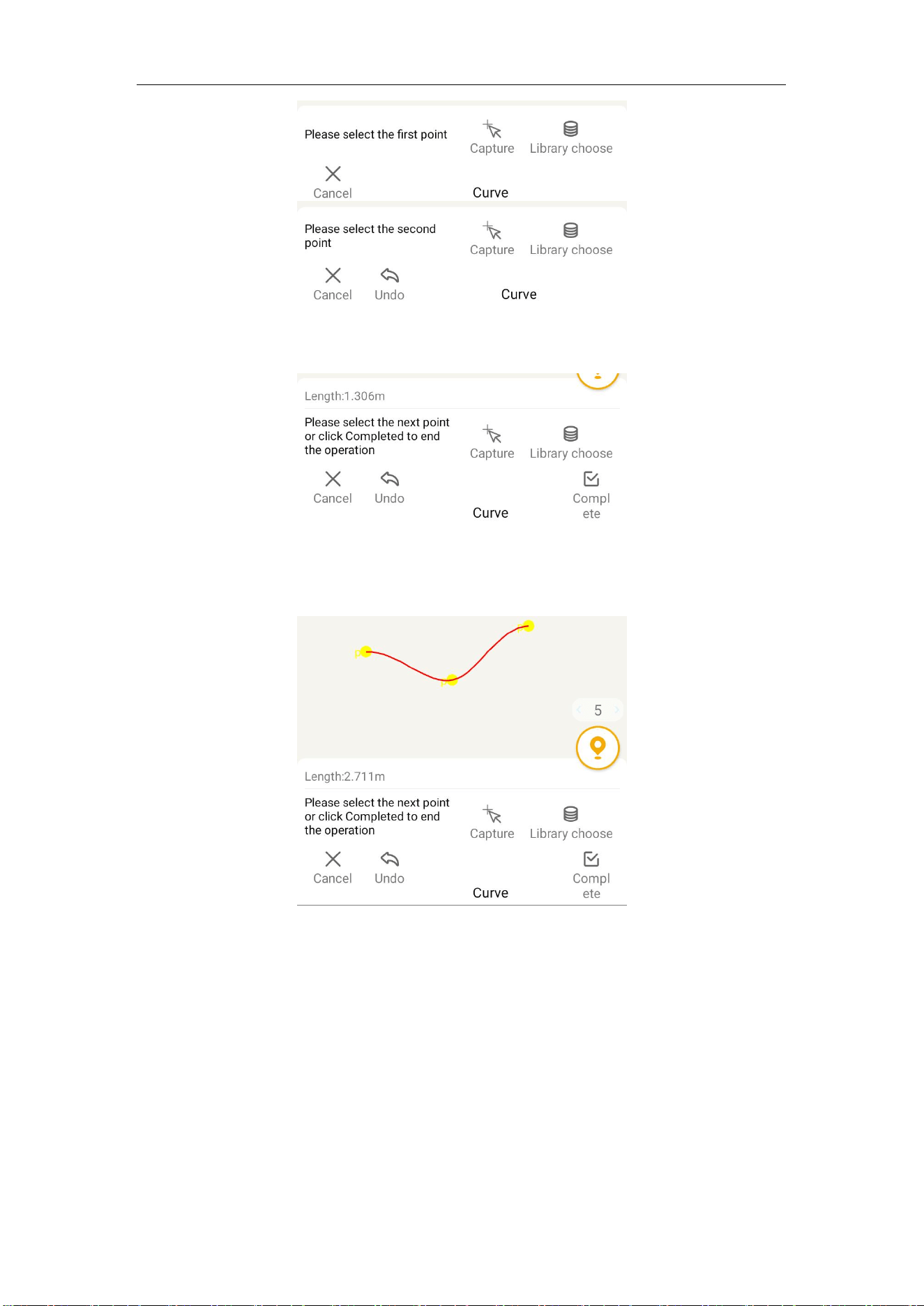
7.2.4 Curve
You can select multiple points by clicking on the map, selecting points with the Capture
tool, or selecting points from Element. They will be automatically connected into curve in
the order of selection.
The drawing steps are as follows:
1) Select the first point by clicking on the map, selecting points with the Capture tool, or
selecting points from Element. The selected point will be displayed in yellow and will not
be saved to Element. You can click Cancel, which will exit the drawing mode. Clicking
Undo will cancel the selected point.
M8 Laser GNSS Receiver User Guide
54
2) After completing the first point, you will be prompted to select the second point, which
is the same as the first point and will automatically form a connection with the first point.
3) After completing the selection of the second point, you will be prompted below to
select the next point or click Completed. You can continue to select points or click
Completed to save the polyline.
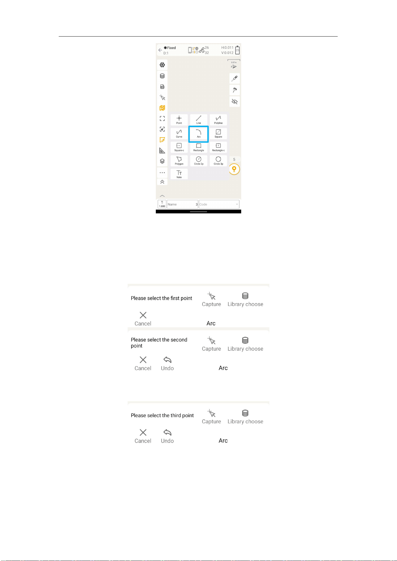
7.2.5 Arc
You can select multiple points by clicking on the map, selecting points with the Capture
tool, or selecting points from Element. They will be automatically connected into Arc in
the order of selection.
M8 Laser GNSS Receiver User Guide
55
The drawing steps are as follows:
1) Select the first point by clicking on the map, selecting points with the Capture tool, or
selecting points from Element. The selected point will be displayed in yellow and will not
be saved to Element. You can click Cancel, which will exit the drawing mode. Clicking
Undo will cancel the selected point.
2) After completing the first point, you will be prompted to select the second point, which
is the same as the first point.
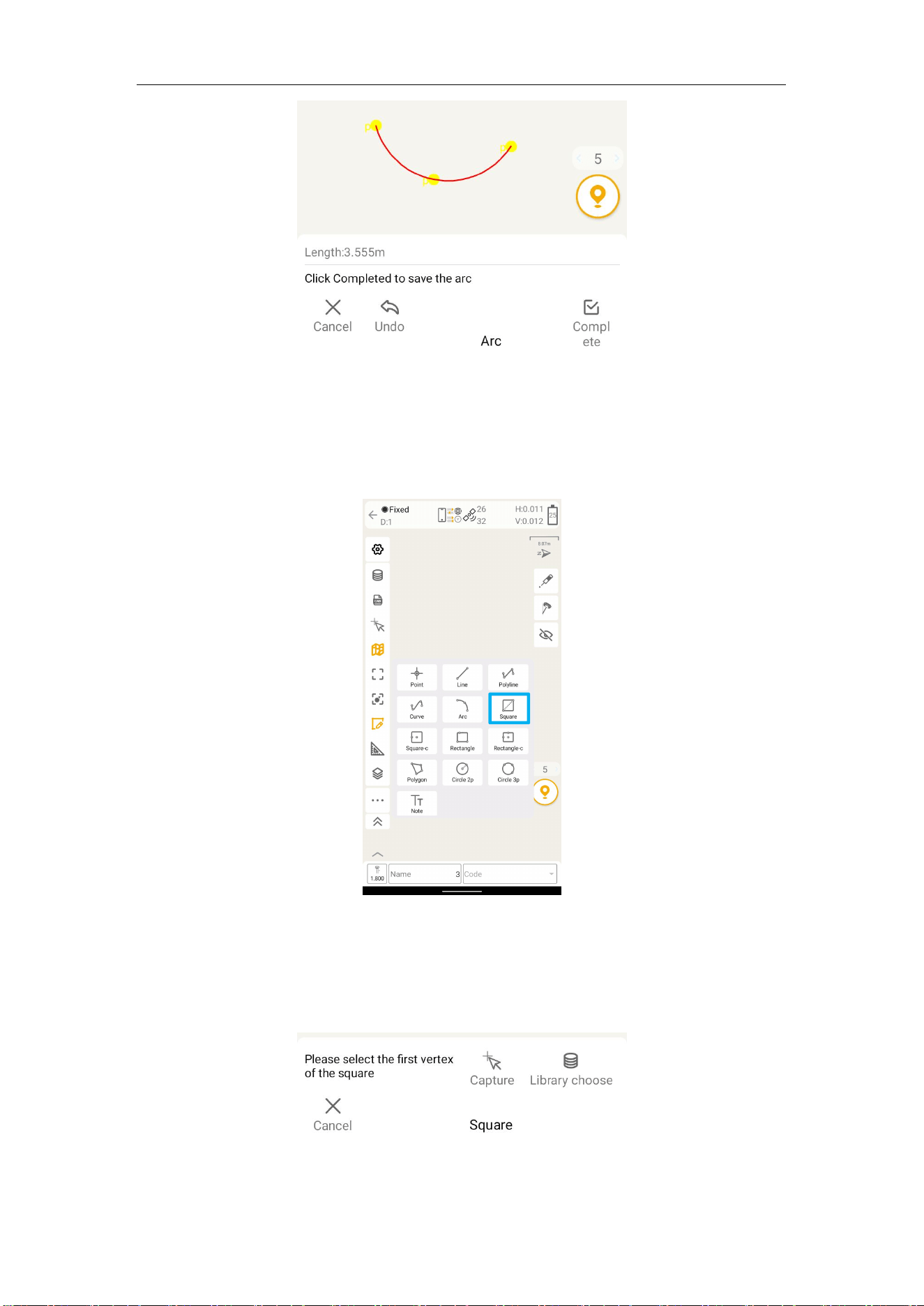
3) After completing the selection of the second point, you will be prompted below to
select the third point. After selecting the point, connect it with the first two points to form
an arc. Click Completed to complete the operation.
M8 Laser GNSS Receiver User Guide
56
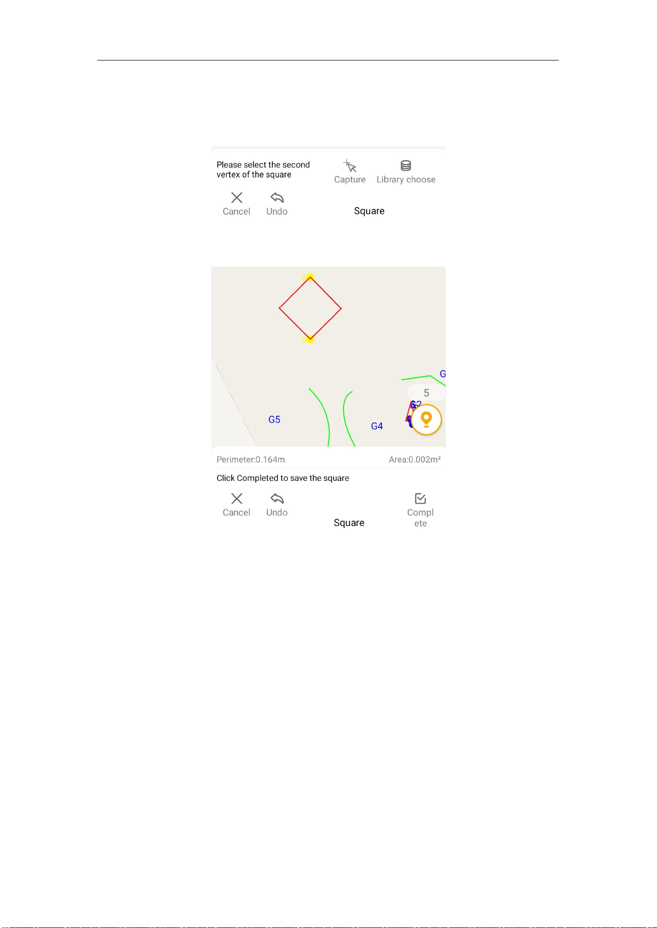
7.2.6 Square
You can select the first vertex and the second vertex of the square to complete the square
by clicking on the map, selecting points with the Capture tool, or selecting points from
Element.
The drawing steps are as follows:
1) Select the first vertex of the square by clicking on the map, selecting points with the
Capture tool, or selecting points from Element. The selected point will be displayed in
yellow and will not be saved to Element. You can click Cancel to exit the drawing mode.
M8 Laser GNSS Receiver User Guide
57
2) After completing the first point selection, select the second vertex by clicking on the
map, selecting points with the Capture tool, or selecting points from Element. The
selected point will be displayed in yellow and will not be saved to Element. You can click
Cancel to exit the drawing mode. Click Undo will cancel the selected point.
3) After completing the selection of the second vertex, the bottom prompts "Click
Completed to save the square". Click Completed to complete the square drawing.
7.2.7 Square-c
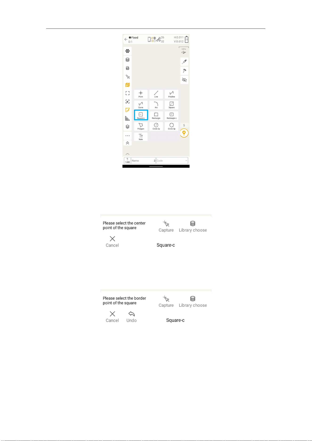
You can select the center point and the border points to form a square by clicking on the
map, selecting points with the Capture tool, or selecting points from Element.
M8 Laser GNSS Receiver User Guide
58
The drawing steps are as follows:
1) Select the center point of the square by clicking on the map, selecting points with the
Capture tool, or selecting points from Element. The selected point will be displayed in
yellow and will not be saved to Element. You can click Cancel to exit the drawing mode.
2) After completing the center point selection, select the square border point by clicking
on the map, selecting points with the Capture tool, or selecting points from Element. The
selected point will be displayed in yellow and will not be saved to Element. You can click
Cancel to exit the drawing mode. Click Undo will cancel the selected point.
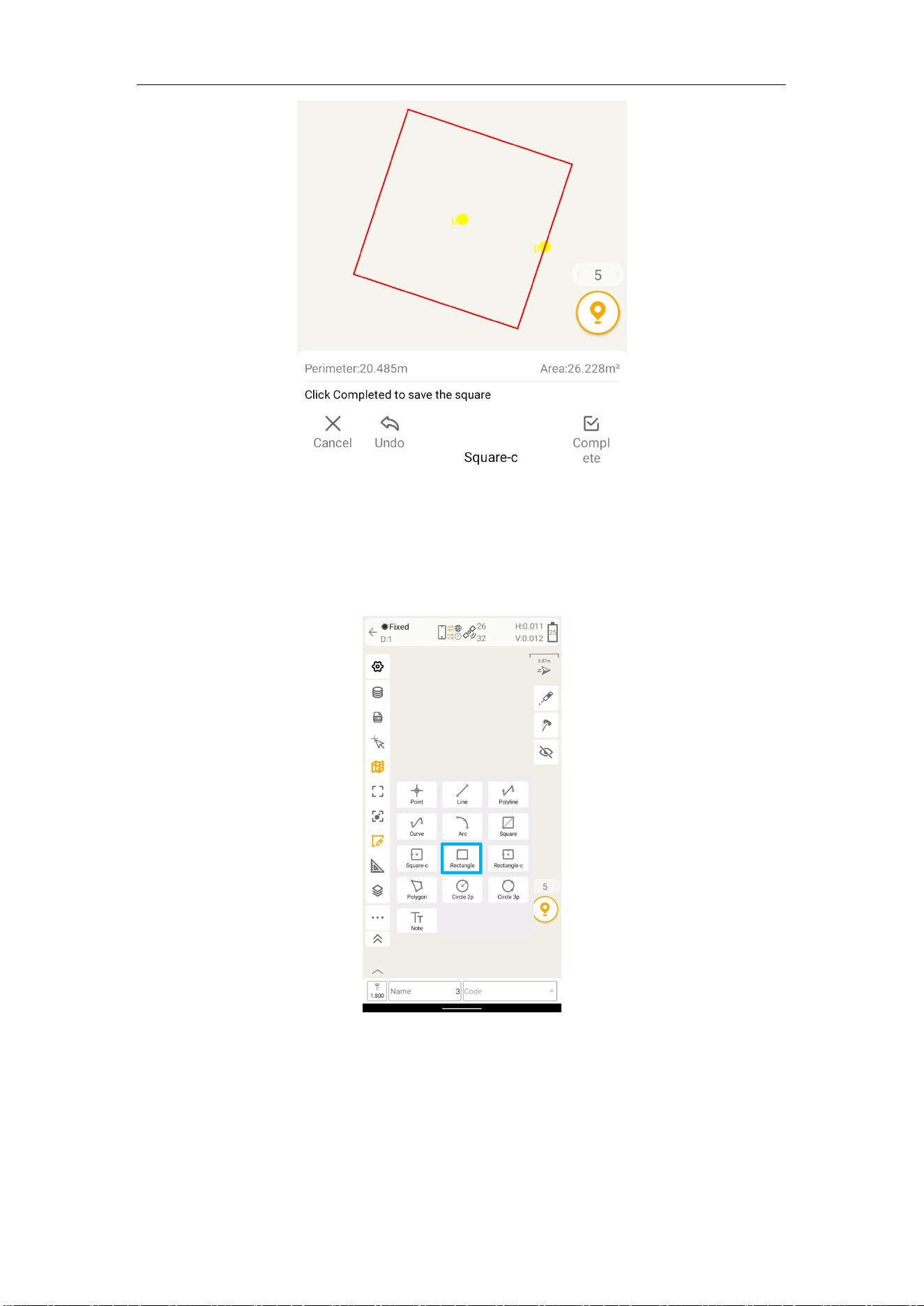
3) After completing the selection of the square border point, the bottom prompts "Click
Completed to save the square". Click Completed to complete the square drawing.
M8 Laser GNSS Receiver User Guide
59
7.2.8 Rectangle
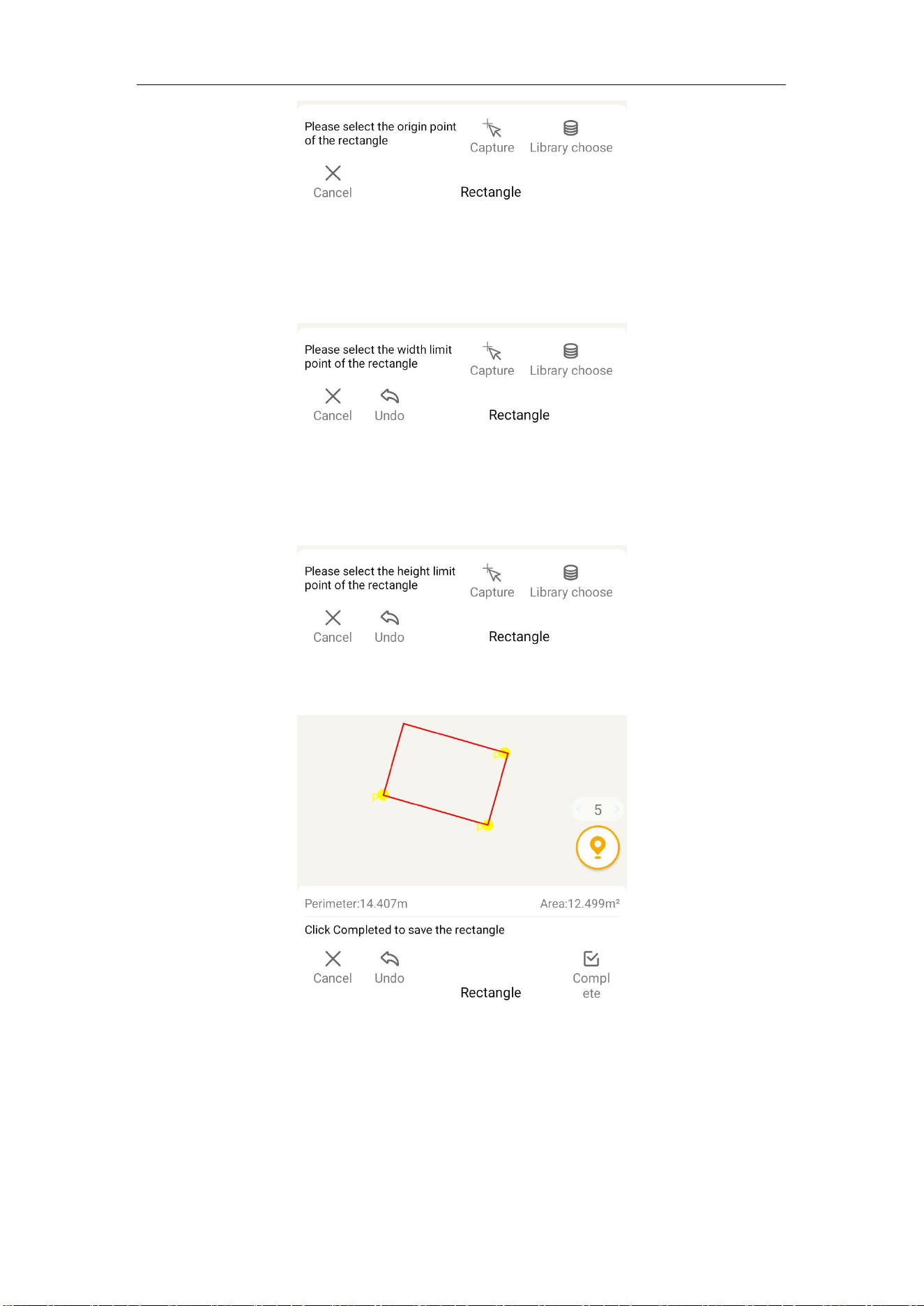
You can select the origin point of the rectangle, the width limit point and the height limit
point to complete the rectangle by clicking on the map, selecting points with the Capture
tool, or selecting points from Element.
The drawing steps are as follows:
1) Select the origin point of the rectangle by clicking on the map, selecting points with the
Capture tool, or selecting points from Element. The selected point will be displayed in
yellow and will not be saved to Element. You can click Cancel to exit the drawing mode.
M8 Laser GNSS Receiver User Guide
60
2) After completing the origin point selection, select the width limit point by clicking on
the map, selecting points with the Capture tool, or selecting points from Element. The
selected point will be displayed in yellow and will not be saved to Element. You can click
Cancel to exit the drawing mode. Click Undo will cancel the selected point.
3) After completing the width limit point selection, select the height limit point by clicking
on the map, selecting points with the Capture tool, or selecting points from Element. The
selected point will be displayed in yellow and will not be saved to Element. You can click
Cancel to exit the drawing mode. Click Undo will cancel the selected point.
4) After completing the selection of the height limit point, the bottom prompts "Click
Completed to save the rectangle". Click Completed to complete the rectangle drawing.
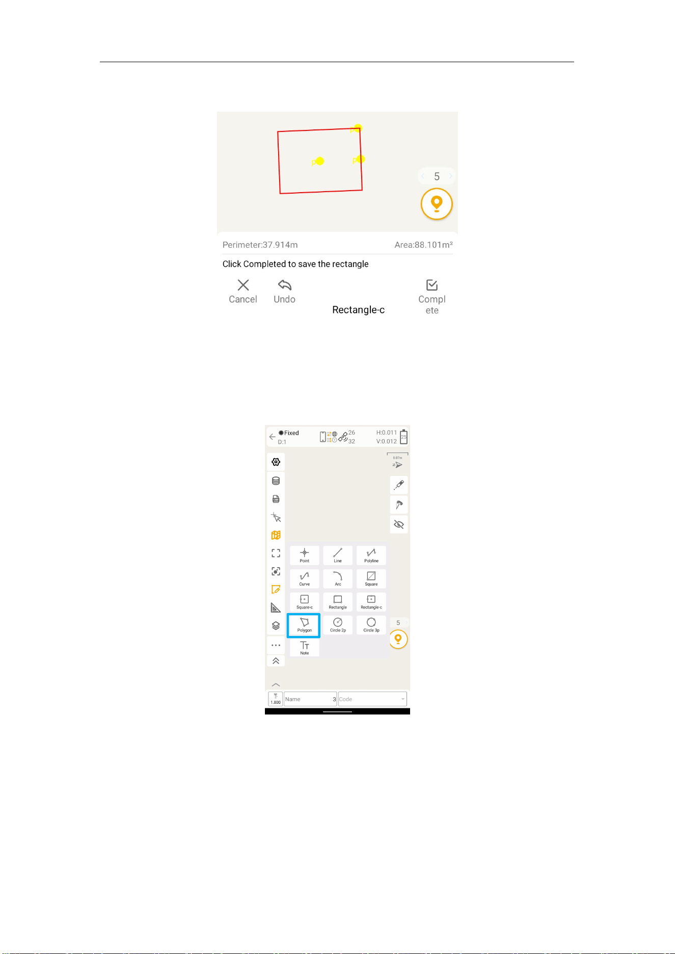
7.2.9 Rectangle-c
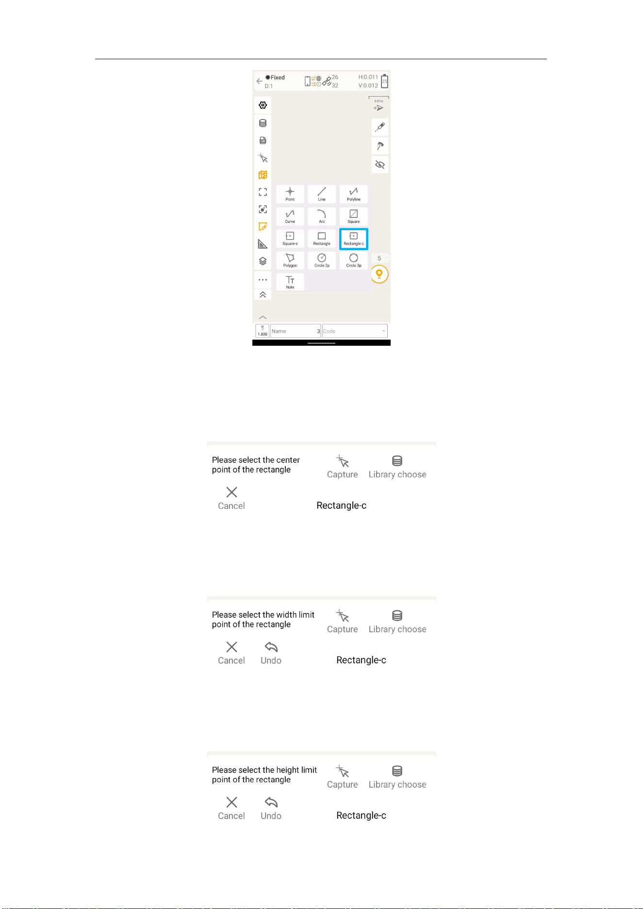
You can select the center point of the rectangle, the width limit point and the height limit
point to complete the rectangle by clicking on the map, selecting points with the Capture
tool, or selecting points from Element.
M8 Laser GNSS Receiver User Guide
61
The drawing steps are as follows:
1) Select the center point of the rectangle by clicking on the map, selecting points with
the Capture tool, or selecting points from Element. The selected point will be displayed in
yellow and will not be saved to Element. You can click Cancel to exit the drawing mode.
2) After completing the center point selection, select the width limit point by clicking on
the map, selecting points with the Capture tool, or selecting points from Element. The
selected point will be displayed in yellow and will not be saved to Element. You can click
Cancel to exit the drawing mode. Click Undo will cancel the selected point.
3) After completing the width limit point selection, select the height limit point by clicking
on the map, selecting points with the Capture tool, or selecting points from Element. The
selected point will be displayed in yellow and will not be saved to Element. You can click
Cancel to exit the drawing mode. Click Undo will cancel the selected point.
M8 Laser GNSS Receiver User Guide
62
4) After completing the selection of the height limit point, the bottom prompts "Click
Completed to save the rectangle". Click Completed to complete the rectangle drawing.
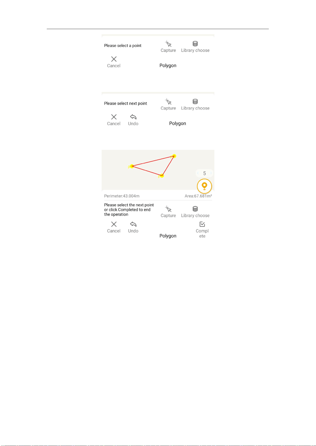
7.2.10 Polygon
You can select multiple points by clicking on the map, selecting points with the Capture
tool, or selecting points from Element. They will be automatically connected into polygon
in the order of selection.
The drawing steps are as follows:
1) Select the first point by clicking on the map, selecting points with the Capture tool, or
selecting points from Element. The selected point will be displayed in yellow and will not
be saved to Element. You can click Cancel, which will exit the drawing mode. Clicking
Undo will cancel the selected point.
M8 Laser GNSS Receiver User Guide
63
2) After completing the first point, you will be prompted to select the next point, which is
the same as the first point and will automatically form a connection with the first point.
3) Repeat the second step. The bottom prompts "Please select the next point or click
Completed to end the operation" Click Completed to complete the drawing of the polygon.
7.2.11 Circle 2p
Draw a circle with the distance between two points as the radius by clicking on the map,
selecting points with the Capture tool, or selecting points from Element.