Shanghai AllyNav Technology Co.,Ltd.
ALLYNAV R73 GNSS
RECEIVER
operation manual
Shanghai AllyNav Technology Co.,Ltd.
Shanghai AllyNav Technology Co.,Ltd.

Shanghai AllyNav
Technology Co.,Ltd.
foreword
disclaimer
We are committed to continuously improving the function and performance of
our products, and the product specifications and manual contents may change without
prior notice.If there is any difference between the ICONS and pictures in the manual
and the actual product, please refer to the actual product.The company reserves the
right of final interpretation of all technical parameters and graphic information .
Before using this product, please read this manual carefully.For failure to
follow the requirements of the manual or fail to correctly understand the requirements
of the manual and misoperation of this product, the company will not be responsible
for any loss.
The product is designed to withstand certain harsh environments.However, this
device is a high-precision electronic instrument and should be treated with
care.Operating or storing the receiver outside the specified temperature range may
damage it .
Technology and service
If you have any questions and the product documentation fails to provide
relevant information, please contact your local office Technology. Or go to the joint
navigation website (http: / / www.allynav. Cn) query download the latest version of
the product and related technical information, can also call the national service hotline:
Address: 2nd floor, Building 1, Lane 215, Gaoguang Road, Qingpu District, Shanghai
Contact number: 021-51340805 website: www.allynav.cn
400-1698-003 contact us, we will serve you wholeheartedly
Document revision record
version
number
Revised records
Revised date
V1.0
found
2023.11.12
V1.1
Update the WEBUI configuration mode
2024.01.21
V1.2
Supplement the WEBUI
function
2024.05.28
V1.3
updated parameter
2024.07.11

Address: 2nd floor, Building 1, Lane 215, Gaoguang Road, Qingpu District, Shanghai
Contact number: 021-51340805 website: www.allynav.cn
catalogue
Chapter 1: Product Overview ..................................................................... 1
1.1 Product Introduction ....................................................................... 1
1.2 Main characteristics ........................................................................ 1
1.3 List of items .................................................................................... 2
Chapter 2: Hardware Composition ............................................................. 3
2.1 Dimensions ..................................................................................... 3
2.2 Interface definition .......................................................................... 4
2.3 Serial port communication .............................................................. 5
Chapter 3. Product Installation ................................................................... 5
3.1 Precautions ...................................................................................... 6
3.2 Installation direction ....................................................................... 6
3.3 Installation method ......................................................................... 8
3.4 Data transmission and power supply line connection .................... 8
Chapter 4 Functional introduction .............................................................. 9
4.1 G NSS Introduction ........................................................................ 9
4.2 Introduction to the IMU .................................................................. 9
Chapter 5. Operating instructions ............................................................. 11
5.1 Start-up and startup ....................................................................... 11
5.2 Firmware upgrade ......................................................................... 11
5.3 Configure the receiver .................................................................. 13
Appendix A:, FAQ .................................................................................... 19
Appendix B: Technical specifications ...................................................... 22
Appendix C: commands and messages..................................................... 25
Chapter 6 WEBUI Web page Configuration ............................................ 25

Shanghai AllyNav
Technology Co.,Ltd.
Page 11
Chapter1 Product overview
1.1product brief introduction
R73-GNSS receiver is one of the new positioning and orientation series
products independently developed by Shanghai Lianshi Navigation Technology Co.,
LTD.The product has built-in dual satellite antenna, Beidou /GNSS high-precision
board, radio communication module, inertial navigation module and 4G module,
which realizes the function of single antenna positioning and double antenna
orientation.The R73-GNSS receiver is suitable for aquatic applications, and can be
widely used in construction machinery and agricultural navigation fields .
The product has the features of integrated design, simple installation, etc., and
can be easily installed on the hull surface or bracket.Maintenance-free design
eliminates the need for routine maintenance.The receiver provides heading
information through the GNSS system and is free from geomagnetic interference,
making it ideal for conventional Marine, river or land applications.
1.2main feature
⚫ High precision, low power consumption, using Beidou, GPS, GLONASS,
Galileo, QZSS full-system full-frequency high-precision positioning module,
can ensure positioning accuracy in a variety of complex environments;
⚫ Support SBAS, precise single point positioning PPP function, in the absence
of a fixed base station to meet high-precision heading requirements;
⚫ Compatible with a variety of Beidou /GNSS high-precision positioning
directional board, can achieve a single Beidou solution;
⚫ Wide voltage supply, voltage range 9 ~ 36V DC, with positive and negative
polarity reverse protection;
Address: 2nd floor, Building 1, Lane 215, Gaoguang Road, Qingpu District, Shanghai
Contact number: 021-51340805 website: www.allynav.cn
Page 2
2
⚫ Built-in WiFi module, embedded web function, connect to the WiFi to
configure the device;
⚫ Integrated design, easy installation, standard IP67 waterproof and dustproof
design;
⚫ Built-in high-precision six-axis gyroscope to achieve high-precision attitude
measurement;
⚫ Optional built-in radio, satellite communication module ;
⚫ Built-in eSIM card, CORS signal can be connected to achieve
centimeter-level positioning 。
1.3inventory
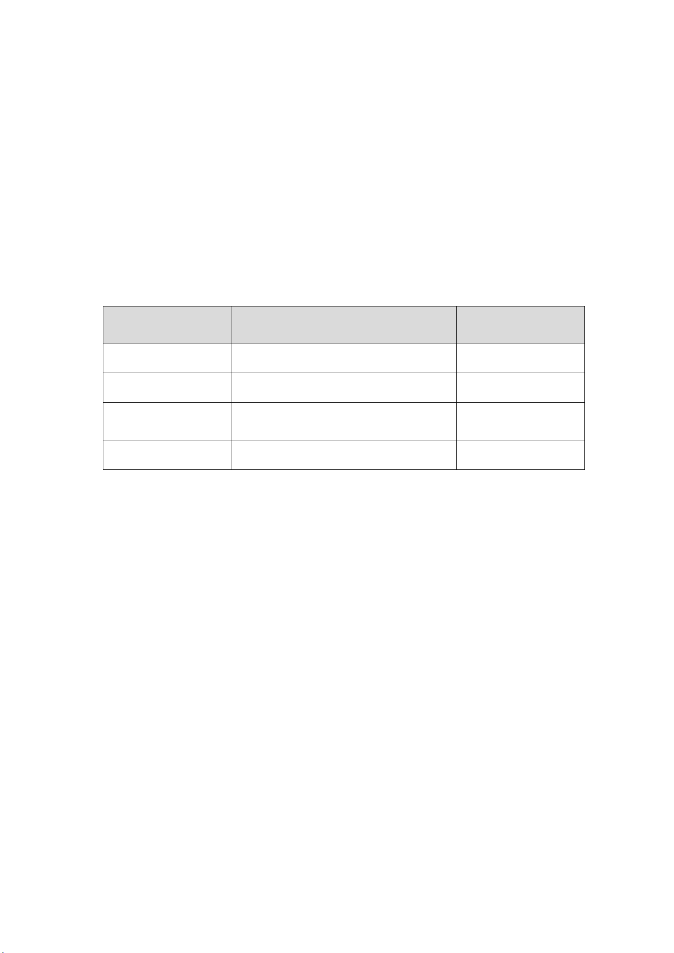
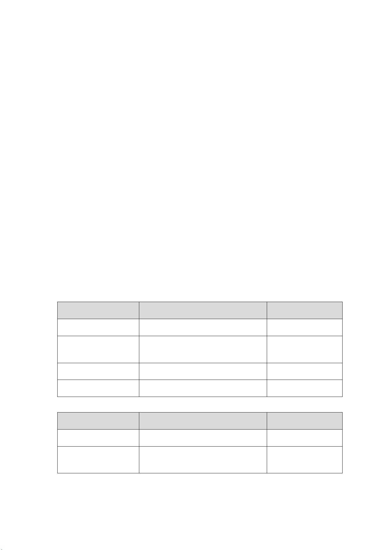
The table is a detailed list of items included when the user purchases the R73 GNSS
receiver.
Table 1-1, List of items
product name
specifications and models
quantity
GNSS receiver
R73(RS-232+RS-232)
1
The R73 data
transmission power
supply line
Optional option: 1.5m / 15m
1
12V appliances
12V 5A
1
mounting bracket
/
1
Table 1-2, List of items
product name
specifications and models
quantity
GNSS receiver
R73(RS-422)
1
The R73 data
transmission power
supply line
30m
1
Address: 2nd floor, Building 1, Lane 215, Gaoguang Road, Qingpu District, Shanghai
Contact number: 021-51340805 website: www.allynav.cn
Page 2
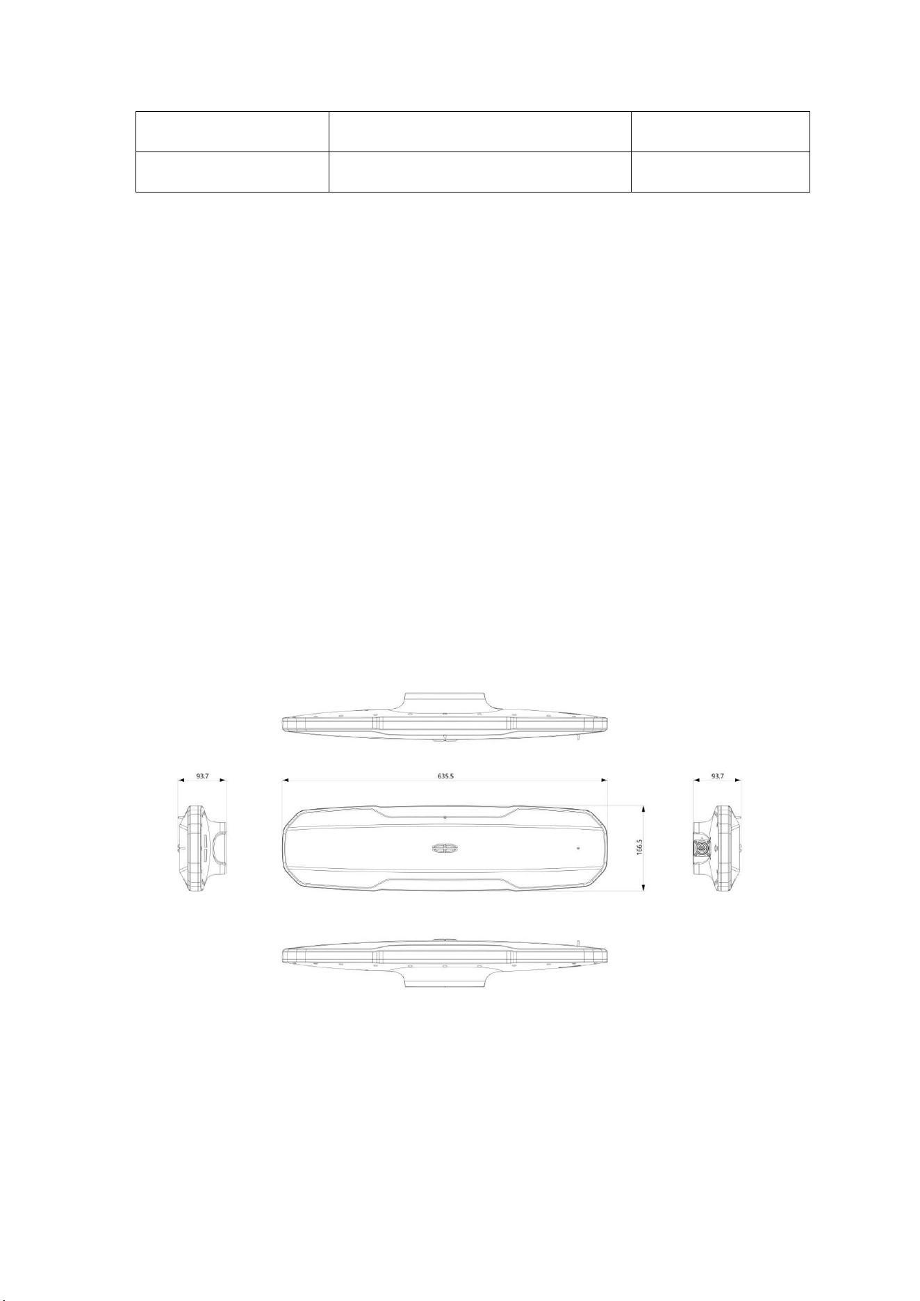
3
12V appliances
12V 5A
1
mounting bracket
/
1
Chapter 2: Hardware Composition
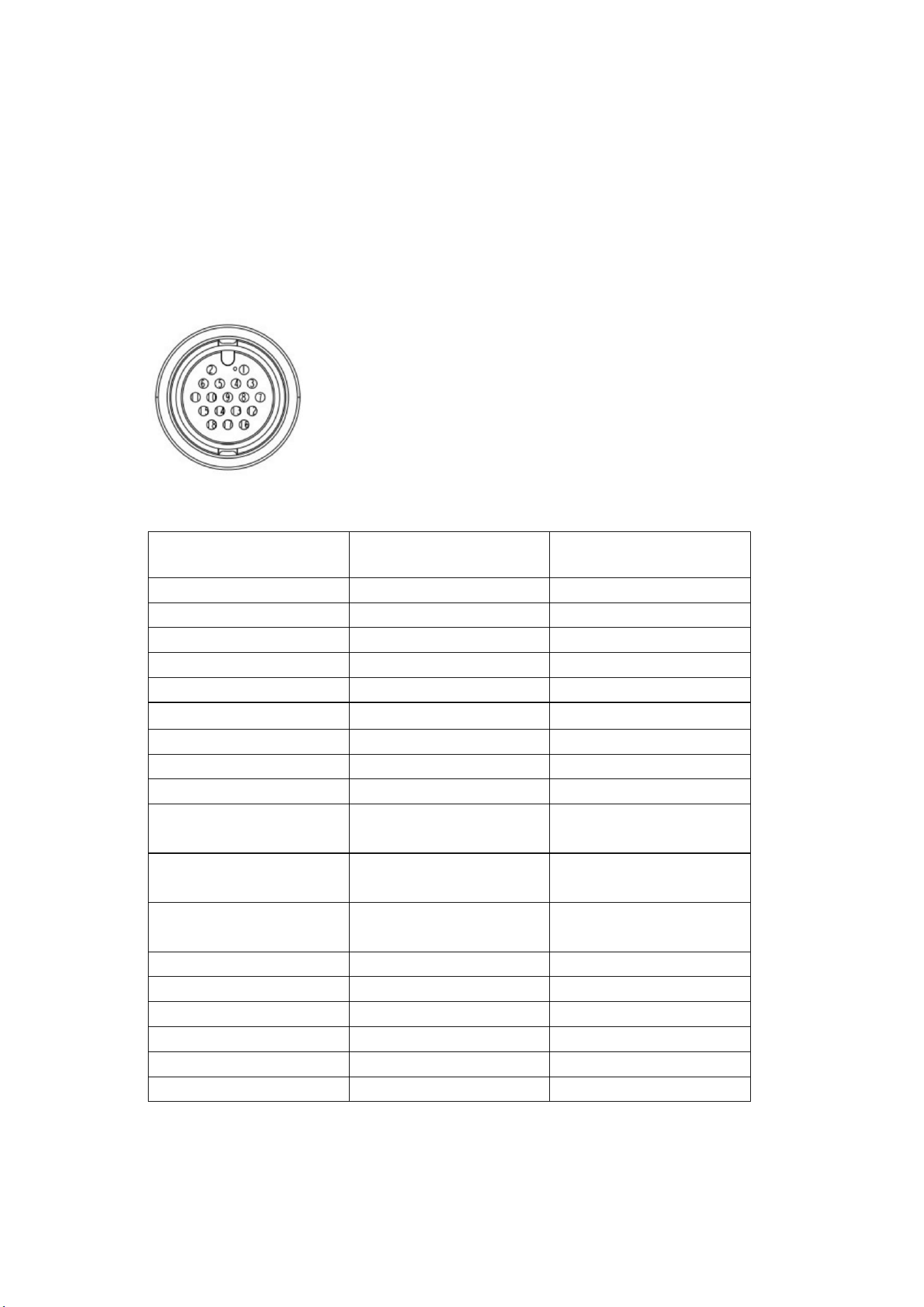
2.1 Dimensions
Figure 2-1 Structural dimensions of R 73
Address: 2nd floor, Building 1, Lane 215, Gaoguang Road, Qingpu District, Shanghai
Contact number: 021-51340805 website: www.allynav.cn
Page 2
4
2.2 Interface definition
R73 GNSS The receiver adopts 18-PIN interface and supports RS-232 level. Figure
2-2 below shows the pin layout of the receiver interface. Table 2-1 lists the signal
types for each pin.
Figure 2-2 R73 pin layout
Table 2-1 Specification table of cable pins
Aviation PIN
order
definition
port
1
USB-DP
USB+
2
VCC12V
obligate
3
CAN-H
obligate
4
USB-DM
USB-
5
USB-VBUS
VBUS
6
VCC12V
positive pole
7
CAN-L
obligate
8
NC
Empty feet
9
GND
source GND
10
RS422-Y
Not connected when using
RS232
11
RS422-Z
Not connected when using
RS232
12
RS232-TX1
The RS232 emission is
introduced
13
GND
source GND
14
RS232-RX2/RS422-A
Not using RS232
15
RS232-TX2/RS422-B
Not using RS232
16
RS232-RX1
The RS232 is received
17
GND-O
Serial port-dedicated GND
18
GND-O
Serial port-dedicated GND
Address: 2nd floor, Building 1, Lane 215, Gaoguang Road, Qingpu District, Shanghai
Contact number: 021-51340805 website: www.allynav.cn
Page 2
5
2.3 Serial port communication
R73 GNSS The receiver has two serial ports of the RS232 level, where the serial
port 1 is used to configure the receiver and is also available for firmware updates.
Received IMU data default serial port 2 (not configurable, do only receive), IMU
filter data and GNSS board card through the transmission statement. The serial port
default configuration statement is as follows:
Table 2-2 Serial configuration of serial ports
gorge line
Baud rate
NMEA sentence
Data update rate
String mouth 1
115200
GPGGA ,GPVTG ,GPHDT ,GPGSA ,GPGSV
1hz
String mouth 2
115200
GPGGA ,GPVTG ,GPHDT ,GPGSA ,GPGSV
1hz
Serial port 1 is configured as a serial port, can be configured serial port 1 and
serial port 2 output GNSS statement and IMU statement, output frequency and wave
rate, etc., the user can be configured through the web page according to the actual
requirements.
pay attention to:
1. The message output by IMU is filtered and transmitted from GNSS board card. The
statements (GPGGA, GPVTDA, GPVTG, GPHDT, GPGSA, GPGSV) only support
configuration (GPGGA, GPRMC, GPHDT, GPZDA), and other statements are sent to
IMU by GNSS board card. Therefore, Serial port 2 output IMU filtering statements
and GNSS board.
Chapter 3. Product Installation
This chapter describes the installation of R73 GNSS receiver, including matters
needing installation, selection of installation direction and optional installation
method.

Address: 2nd floor, Building 1, Lane 215, Gaoguang Road, Qingpu District, Shanghai
Contact number: 021-51340805 website: www.allynav.cn
Page 2
6
3.1 Precautions
R73 GNSS The following factors should be considered during the installation of
the receiver:
1. R73 GNSS receiver must be installed in the outdoor environment (to avoid
shielding), otherwise the equipment can not work normally;
2, the power supply voltage of the receiver must be 9~36V DC, please pay attention to
the positive and negative electrode corresponding correct;
3, the receiver cable connection must be firm, not virtual connection, wrong
connection, otherwise affect the normal operation of the system;
4, electromagnetic environment notes, GNSS equipment may be disturbed by other
radio equipment, such as wireless network bridge, wireless wiring, camera, intercom,
car burglar alarm, mobile phone signal shield, etc., may interfere with GNSS signal
and radio signal, the working area needs to consider the electromagnetic environment;
5. When configthe receiver, ensure that the power supply and positioning of the
receiver are normal;
6. Please complete the installation of receiver related cable connection and SIM card
before power on;
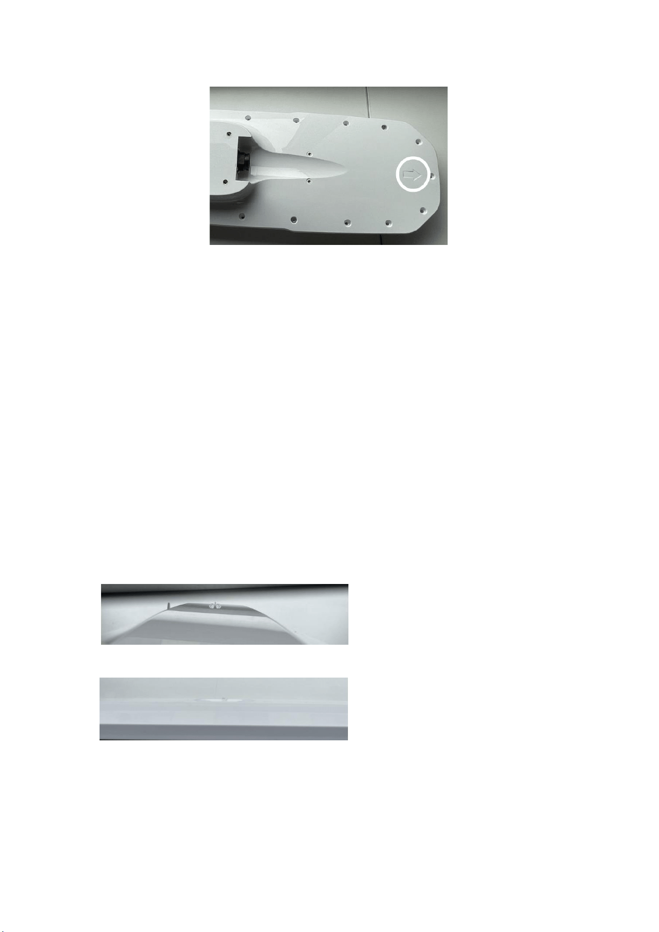
7. Please follow the arrow at the bottom of the shell as the bow direction when
installing.
3.2 Installation direction
R73 GNSSS The receiver integrates two GNSS four-system full-frequency
built-in measurement antennas, namely the main antenna and secondary antenna, in
which the main antenna is used for positioning, and the main antenna and secondary
antenna are combined to obtain heading information. R73 GNSS The arrow at the
bottom of the receiver (marked in the white circle) indicates the relative position of
the two antennas, pointing from the main antenna to the secondary antenna.
Address: 2nd floor, Building 1, Lane 215, Gaoguang Road, Qingpu District, Shanghai
Contact number: 021-51340805 website: www.allynav.cn
Page 2
7
graph 3-1
Note: the R73 GNSS receiver can output the ship's heading regardless of the
installation direction, but if the orientation of the R73 GNSS receiver is not consistent
with the ship axis, an angle change positive value needs to be added when calculating
the heading.
Parallel ship axis installation means that the R73 GNSS receiver is parallel to the ship
axis. This direction measures the course as the actual heading, without the need to
change the Angle to the positive value. Parallel installation method is recommended
in actual use.
Installation direction calibration
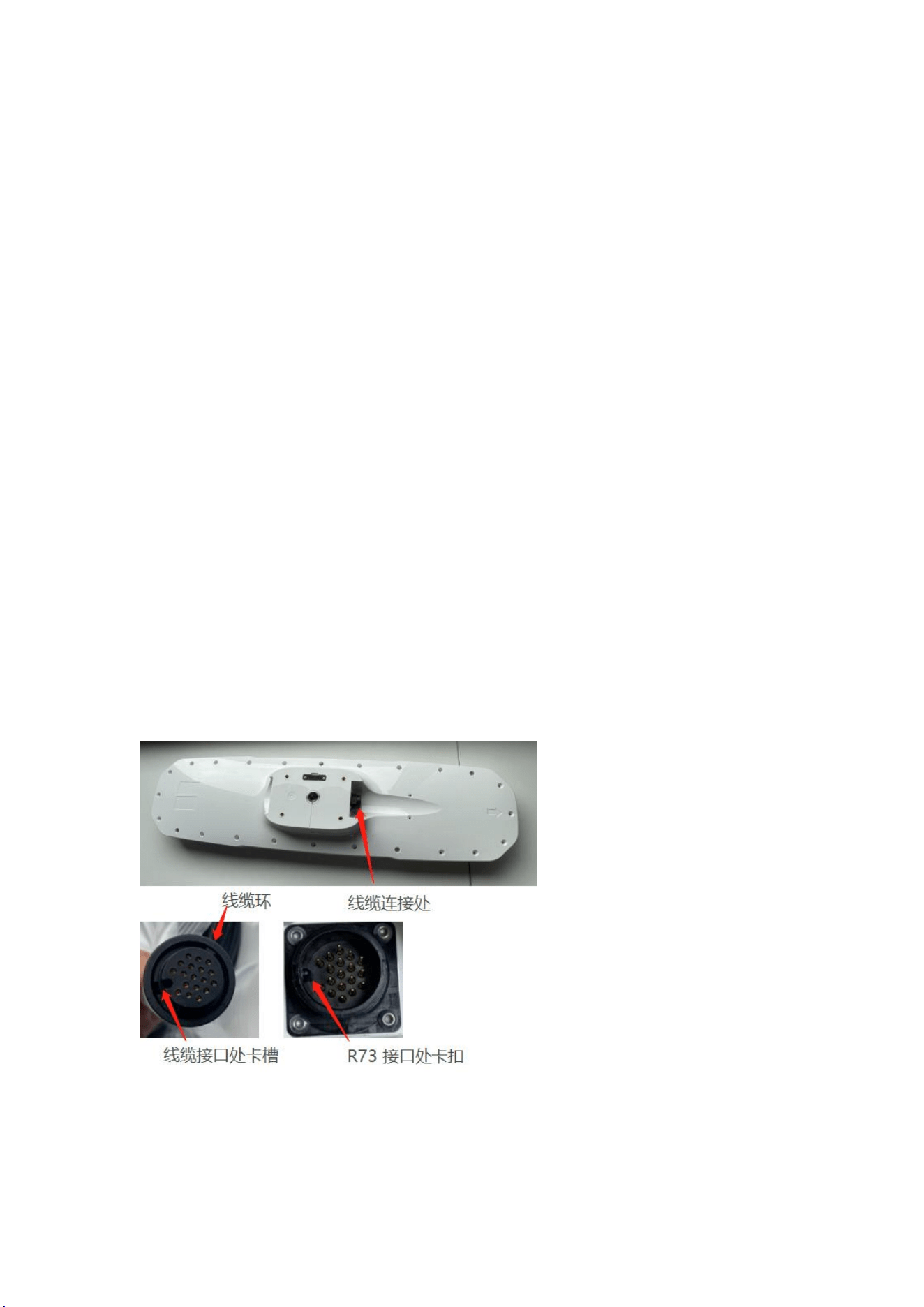
R73 GNSS The receiver adopts visual calibration design, the top raised logo can be
used to calibrate the installation direction, the long axis accuracy accuracy is about ±
1°, and the short axis calibration accuracy is ± 2.5°.
Figure 3-2 Long axis 1 visual calibration
Figure 3-3 Short axis 1 visual calibration
Address: 2nd floor, Building 1, Lane 215, Gaoguang Road, Qingpu District, Shanghai
Contact number: 021-51340805 website: www.allynav.cn
Page 2
8
3.3 Installation method
R73 GNSS The receiver supports two kinds of installation methods: surface
installation and rod installation.
a) Surface mounting ——R73 GNSS receiver has four mounting holes (M5x14
outer hexagonal) for the installation of the equipment on the surface of the carrier;
b) The rod mount ——R73 GNSS receiver has a mounting hole (5 / 8 British screw
hole) at the bottom, which can be mounted on the support rod.
3.4 Data transmission and power supply line connection
R73 GNSS The receiver user can select the 1.5m / 15m / 30m data transmission
power supply line according to the requirements. The specific steps of connecting the
cable and the receiver are as follows:
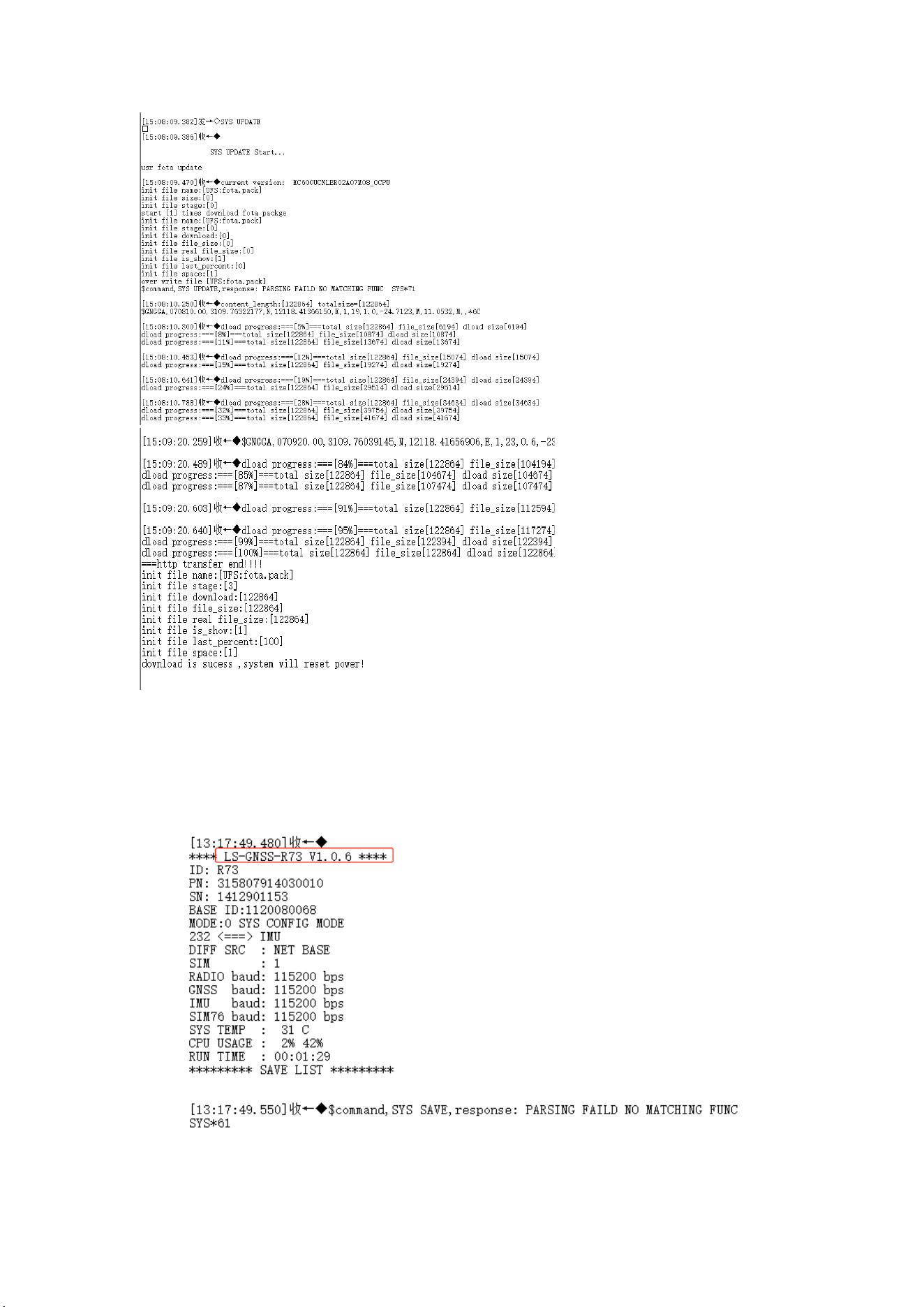
A) Align the card slot at the interface of the data transmission power supply line
with the buckle of the R73 GNSS receiver (as shown in the figure below), insert the
cable into the interface of the R73 GNSS receiver, and rotate the cable ring at the
cable interface clockwise until it is completely fixed;
B) Add the cable clip near the cable connection, and fix the cable clip at the
bottom of the R73 GNSS receiver through screws;

Address: 2nd floor, Building 1, Lane 215, Gaoguang Road, Qingpu District, Shanghai
Contact number: 021-51340805 website: www.allynav.cn
Page 2
9
Ct c) Cover the cable and secure it through screws.
Chapter 4 Functional introduction
4.1 G NSS Introduction
R73 GNSS The receiver integrates a high-precision positioning orientation
board and two GNSS antennas, which can output precise positioning information
and heading information. R73 GNSS The receiver built-in positioning orientation
board card supports Beidou, GPS, GLONASS, Galileo, QZSS and other whole
system full frequency high precision positioning orientation module, can ensure the
positioning accuracy in a variety of complex environments;
The R73 integrates high-precision positioning orientation cards and two GNSS
antennas to output precise positioning information and heading information. Two
GNSS antennas are divided into main antenna and secondary antenna. The main
antenna is used for positioning, and the secondary antenna (bottom arrow of R73) is
used for heading determination.
4.2 Differential mode
RTK (Real Time Kinematic) real-time dynamic measurement
technology
RTK uses a real-time differential technology based on carrier phase
observation. A receiver is installed on the base station, and the base station collects
satellite data, and transmits its observation value and the site coordinate
information to the mobile station through the data chain. While the mobile station
conducts real-time carrier phase differential processing on the satellite data
collected and the received data chain, so as to obtain the centimeter-level

Address: 2nd floor, Building 1, Lane 215, Gaoguang Road, Qingpu District, Shanghai
Contact number: 021-51340805 website: www.allynav.cn
Page 2
10
positioning result.
Precision for the single-point localization of the PPP-B2b
The PPP service B2b signal is broadcast by the Beidou 3 three
geosynchronous orbit (GEO) satellites in China and surrounding areas, and can
provide users with open and free high-precision services. It is also the first
high-precision service signal released by the Beidou system (the positioning
accuracy is less than 20cm).
Precision for the single-point localization of the PPP-E6HAS
The Galileo E6-B signal provides free Galileo and GPS (single-frequency and
multi-frequency) high-precision PPP correction service to improve real-time user
positioning performance (normal positioning accuracy is less than 20cm).
The SBAS star-based enhancement system
SBAS (Satellite-Based Augmentation System), namely star-based
enhancement system, can carry satellite navigation enhanced signal forward in
geostationary orbit (GEO) satellite, which can broadcast a variety of correction
information such as satellite calendar error, satellite clock difference and
ionosphere delay to users, so as to improve the positioning accuracy of the original
satellite navigation system.
4.3 Introduction to the IMU
Built-in high-precision six-axis gyroscope, to achieve high-precision attitude
measurement; used to filter heading data output, heading accuracy is less than 0.3 °
rms.

Address: 2nd floor, Building 1, Lane 215, Gaoguang Road, Qingpu District, Shanghai
Contact number: 021-51340805 website: www.allynav.cn
Page 2
11
Chapter 5. Operating instructions
This chapter describes some basic operations of the R73 GNSS receiver, such as boot
up, data communications, and firmware updates.
5.1 Start-up and startup
R73 GNSS After the receiver is normally connected with the external
equipment, it can be connected with the power supply, and the power supply voltage
is 9~36V DC, with positive and negative polarity reverse connection protection.
Warning: R73 GNSS The receiver has no overvoltage protection, and the power
supply voltage cannot exceed 36V DC.
5.2 Firmware upgrade
The product firmware version is updated periodically to improve performance,
fix errors, or add new features to the product.
Connect the computer to U turn string (RS-232), connect the serial port 1 for
configuration, open the serial port software, select 115200 for port rate, add back to
the car line, and send SYS UPDATE for system upgrade, as shown in Figure 5-1.
Address: 2nd floor, Building 1, Lane 215, Gaoguang Road, Qingpu District, Shanghai
Contact number: 021-51340805 website: www.allynav.cn
Page 2
12
graph 5-1
The progress display percentage is completed, that is, the upgrade is completed,
after the equipment restart is completed, the serial port will receive the system
configuration information. See Figure Figure 5-2 below.
Address: 2nd floor, Building 1, Lane 215, Gaoguang Road, Qingpu District, Shanghai
Contact number: 021-51340805 website: www.allynav.cn
Page 2
13
Figure 5-2 System configuration information
Note: Do not disconnect the R73 GNSS receiver power supply. Do not interrupt
the communication connection between the computer and the receiver until the
firmware upgrade is complete, otherwise the receiver system upgrade will fail. If
the upgrade fails, resend the instructions SYS UPDATE upgrade.
5.3 Configure the receiver
R73 GNSS The receiver can only be configured with serial port 1 by default,
open the serial port software, U turn (RS-232) connects the serial port 1 (RS-232 full
duplex), check "add return line", after the configuration, connect the serial port 1 to
receive GNSS data, and the serial port 2 receives the data of IMU after filtering.
Follow the following operation steps:
Take 20Hz and 5Hz as examples (yellow font users configure according to actual
requirements)
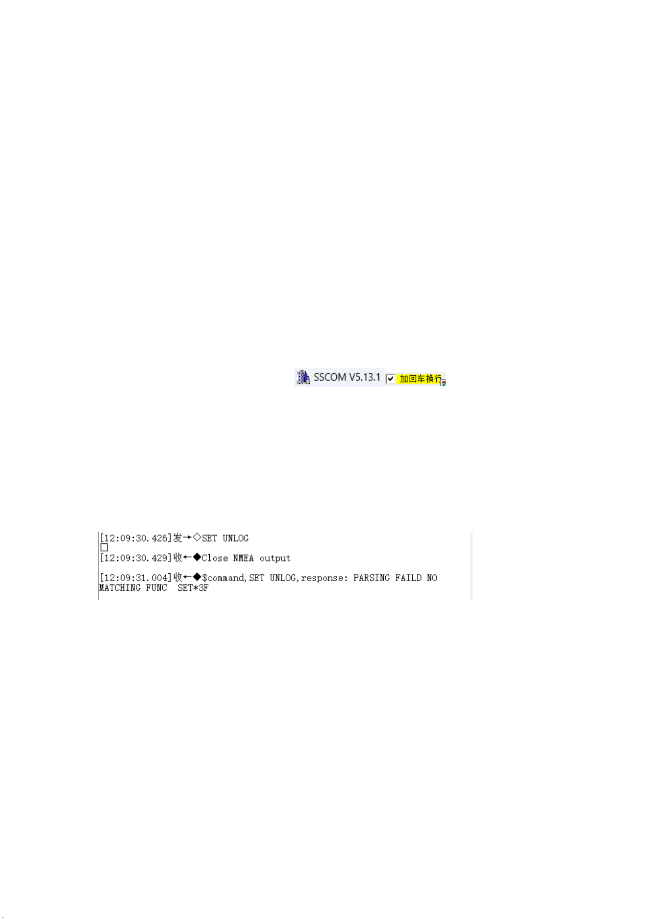
1)Send SET UNLOG / / into configuration mode (GNSS statement and IMU
statement configuration before emptying), and give instruction feedback as
shown in Figure 5-3.
Figure 5-3 Close the GNSS and IMU statement output
2) Switch built-in or external cards (default configuration built-in SIM card SIM
1)
Users can choose to use the built-in card or the external card according to the
actual situation. The external card is a standard SIM card, and the Internet of Things
card and mobile phone card can be used. SIM 1 is built-in card and SIM 2 is external
card.
Address: 2nd floor, Building 1, Lane 215, Gaoguang Road, Qingpu District, Shanghai
Contact number: 021-51340805 website: www.allynav.cn
Page 2
14
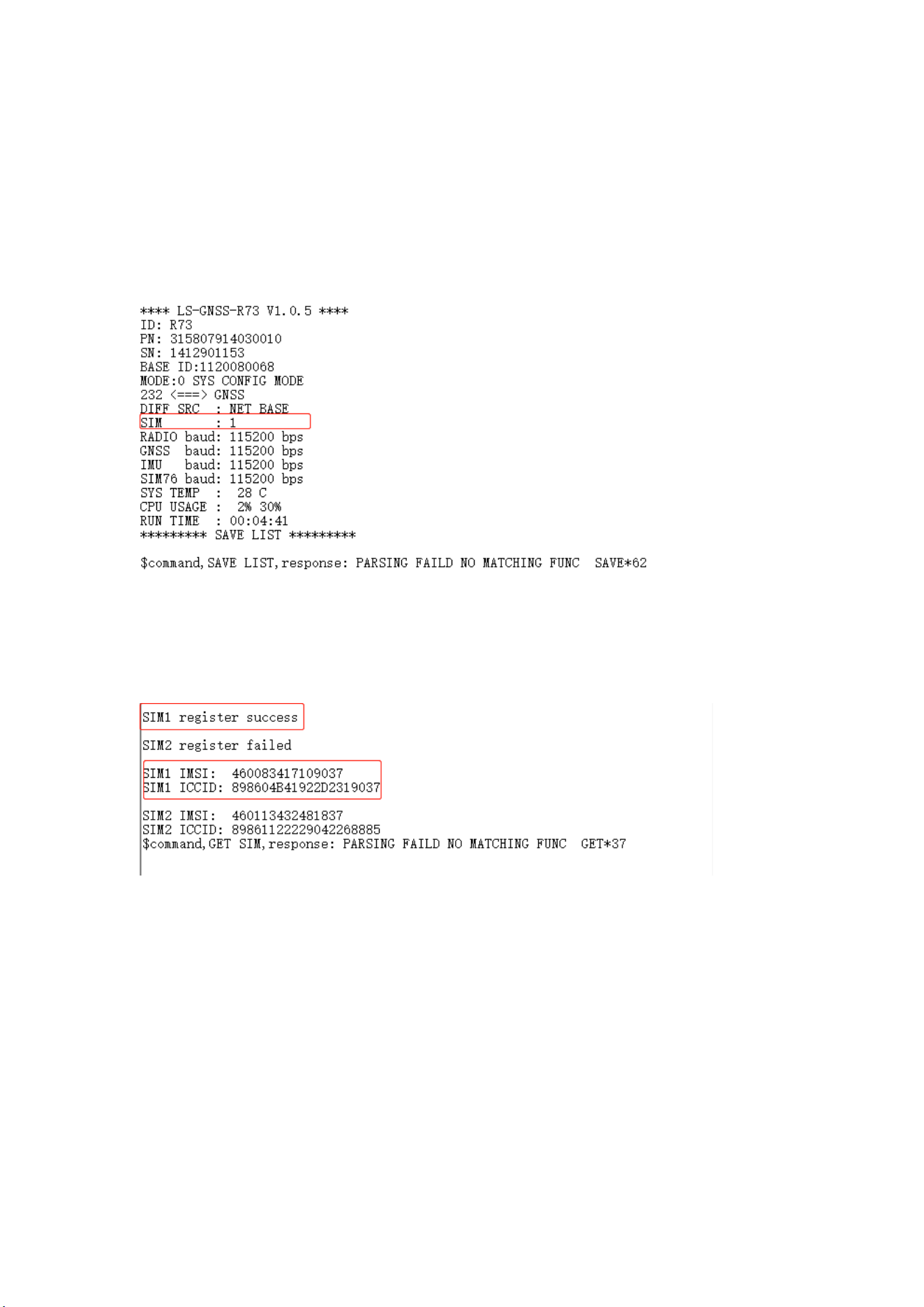
The switching of the SIM 1 instruction is:
SYS CONFIG / / Start the configuration
SET SIM 1 / / Set to the built-in card SIM 1
SYS SAVE / / Save the configuration / read configuration
Instruction feedback such as 5-4 red marked as SIM 1 switching success.
graph 5-4
Send GET SIM to query SIM configuration and launch information, such as 5-5 "SIM
1 register success", 4G launch is successful.
graph 5-5
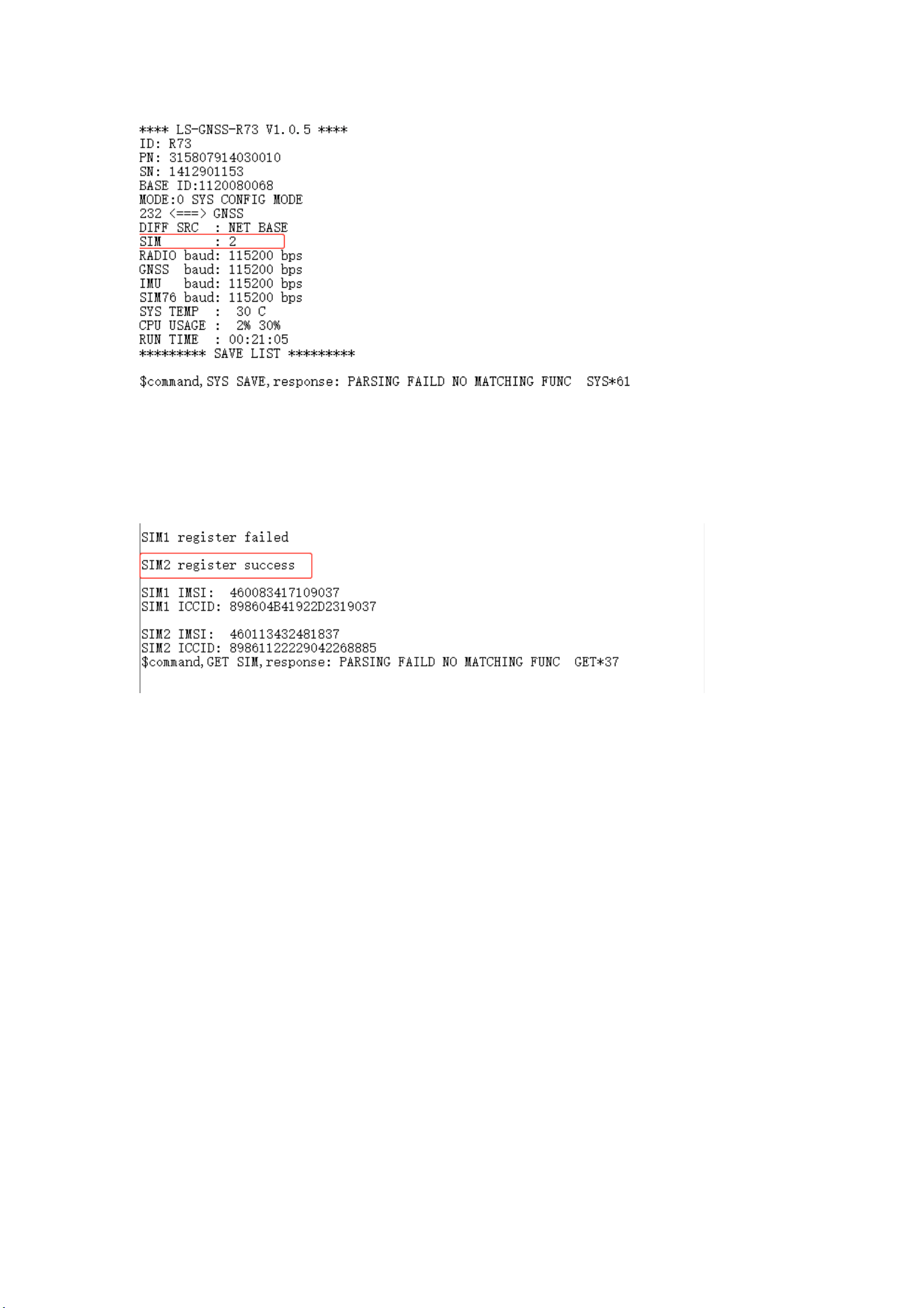
The instruction to switch the external card SIM 2 is:
SYS CONFIG
SET SIM 2
SYS SAVE
The instruction feedback is marked in Figure 5-6 as SIM 2 switching successfully.
Address: 2nd floor, Building 1, Lane 215, Gaoguang Road, Qingpu District, Shanghai
Contact number: 021-51340805 website: www.allynav.cn
Page 2
15
graph 5-6
Send GET SIM to query SIM configuration and launch information, figure 5-7 "SIM
2 register success" is 4G online success.
graph 5-7
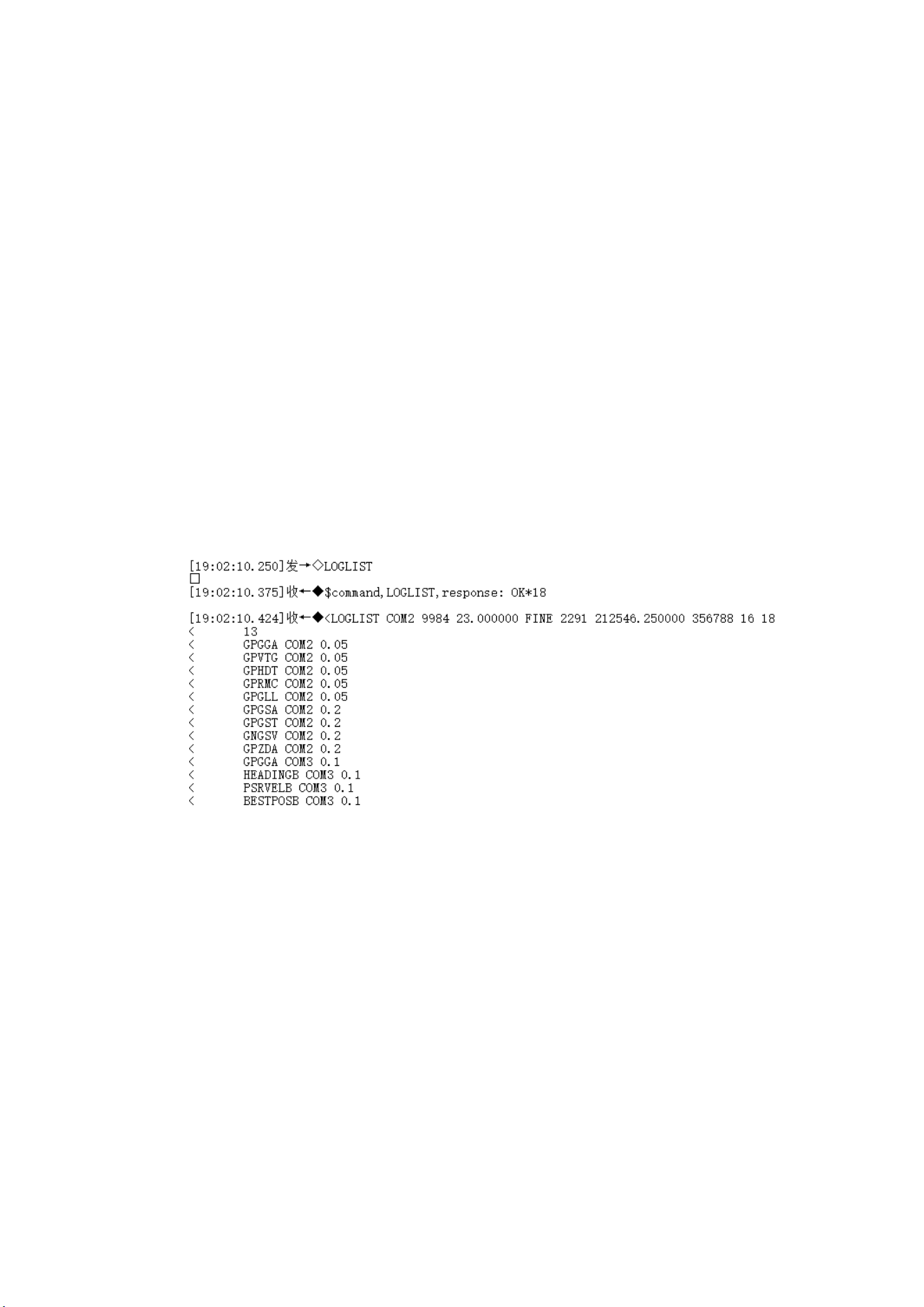
3) Configure GNSS output statements and frequency
GPGGA 0.05 / / Output GPGGA (GNSS location information) at 20Hz
GPVTG 0.05 / / Output the GPVTG (ground speed information) statement at
20Hz
GPHDT 0.05 / / Output the GPHDT (heading information) statement at 20Hz
GPRMC 0.05 / / Output the GPRMC (recommended location information)
statement at 20Hz
GPGLL 0.05 / / Output the GP GLL (latitude and longitude information)
statement at 20Hz
GPZDA 0.2 / / Output the GPZDA (UTC time and date) statement at 5Hz
frequency
Address: 2nd floor, Building 1, Lane 215, Gaoguang Road, Qingpu District, Shanghai
Contact number: 021-51340805 website: www.allynav.cn
Page 2
16
G P GSA 0.2 / / Output the G P GSA (current satellite information) statement
at 5Hz frequency
GPGST 0.2 / / Output the GPGST (false margin error statistics) statement at
5Hz frequency
GPGSV 0.2 / / Output the GPGSV (number of visible satellites) statement at
5Hz frequency
Configure the output GP form statement
CONFIG NMEA0183 V31
NMEATALKER GP
SAVECONFIG / / Save, motherboard instructions
Send a LOGLIST to view the GNSS configuration statement and frequency, as shown
in Figure 5-8.
Figure 5-8 Configure GNSS output statements and frequency, and output GP
form statements
4) Configure the IMU output statement and frequency (send successively, one at
a time)
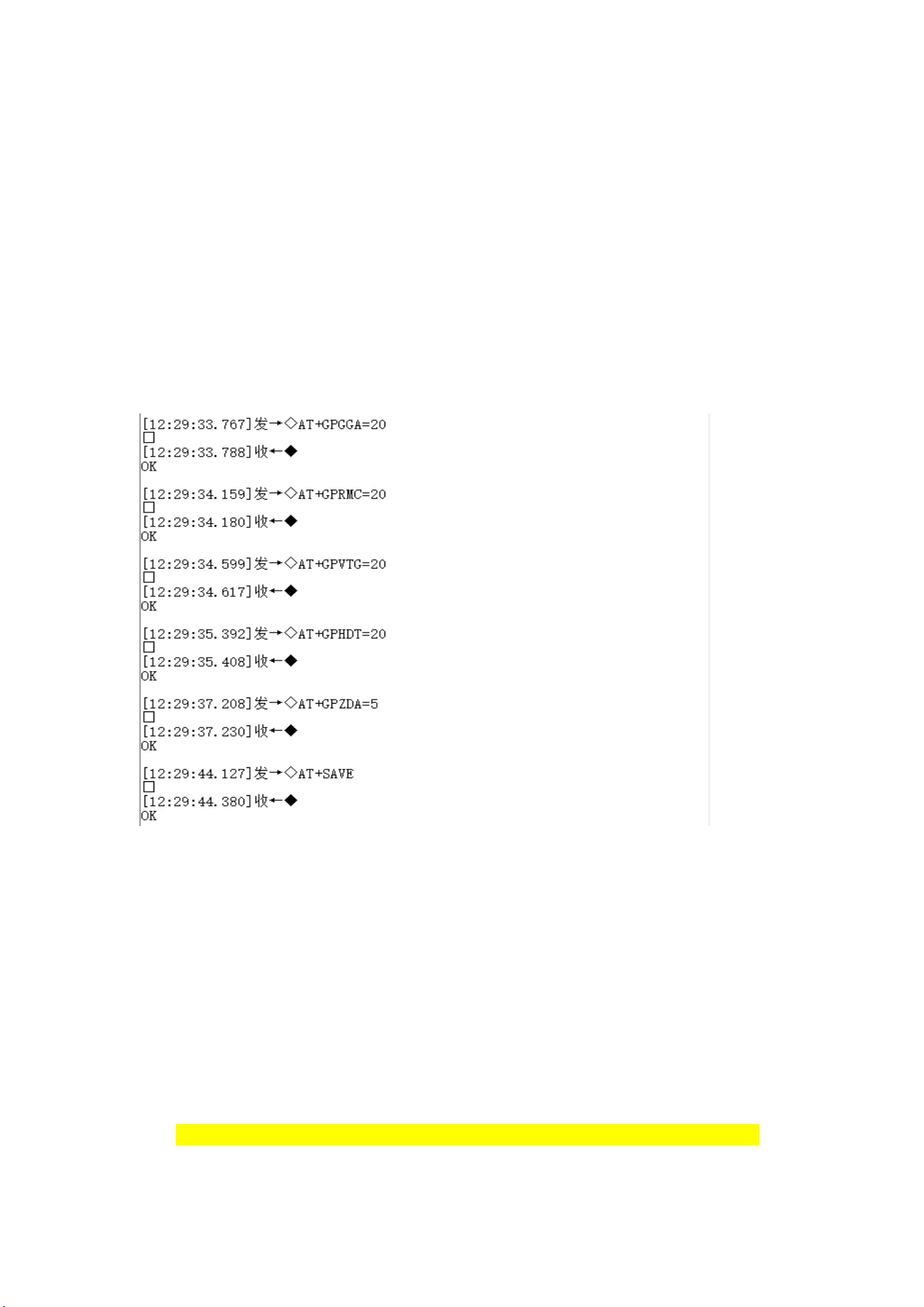
AT + GPGGA = 20 / / Output the GPGGA (GNSS location information)
statement at 20Hz
AT + GPRMC = 20 / / Output the GPRMC (recommended location information)
statement at 20Hz
Address: 2nd floor, Building 1, Lane 215, Gaoguang Road, Qingpu District, Shanghai
Contact number: 021-51340805 website: www.allynav.cn
Page 2
17
AT + GPHDT = 20 / / Outputs the GPHDT (heading information) statement at
20Hz
AT + GPV TG = 20 / / to output the GPV TG (ground speed information)
statement at 20Hz
AT + GPZDA = 5 / / to output the GPZDA (UTC time and date) statement at a
rate of 20Hz
AT + SAVE / / to save
Instruction feedback is shown in Figure Figure 5-9.
Figure 5-9 Configure the IMU output statements and frequencies
matters need attention:
The IMU statement sends one sentence at a time and returns the result
display "OK".
5) Configure to connect CORS base station, instructions (yellow font user
according to the actual use)
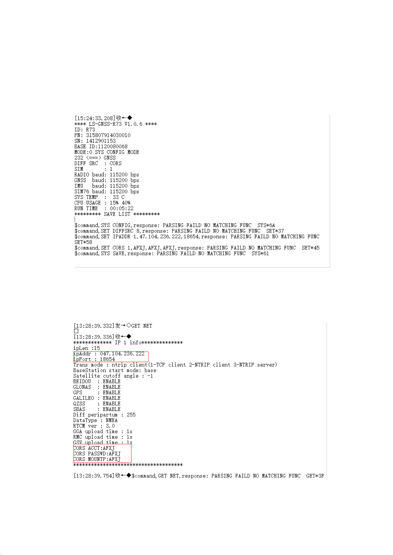
SYS CONFIG / / Start the configuration
SET DIFFSRC 8 / / Set the difference source format as CORS
SET IPADDR 1,47.104.236.222,18654 / / Set up the 1st route, IP address, port
Address: 2nd floor, Building 1, Lane 215, Gaoguang Road, Qingpu District, Shanghai
Contact number: 021-51340805 website: www.allynav.cn
Page 2
18
SET CORS 1, AFXJ, AFXJ, AFXJ / / Set up the 1st route IP, user name,
password, and mount point
SYS SAVE / / Save the configuration / read configuration
Instruction feedback is shown in Figure 5-10.
Figure 5-10 Configure network information
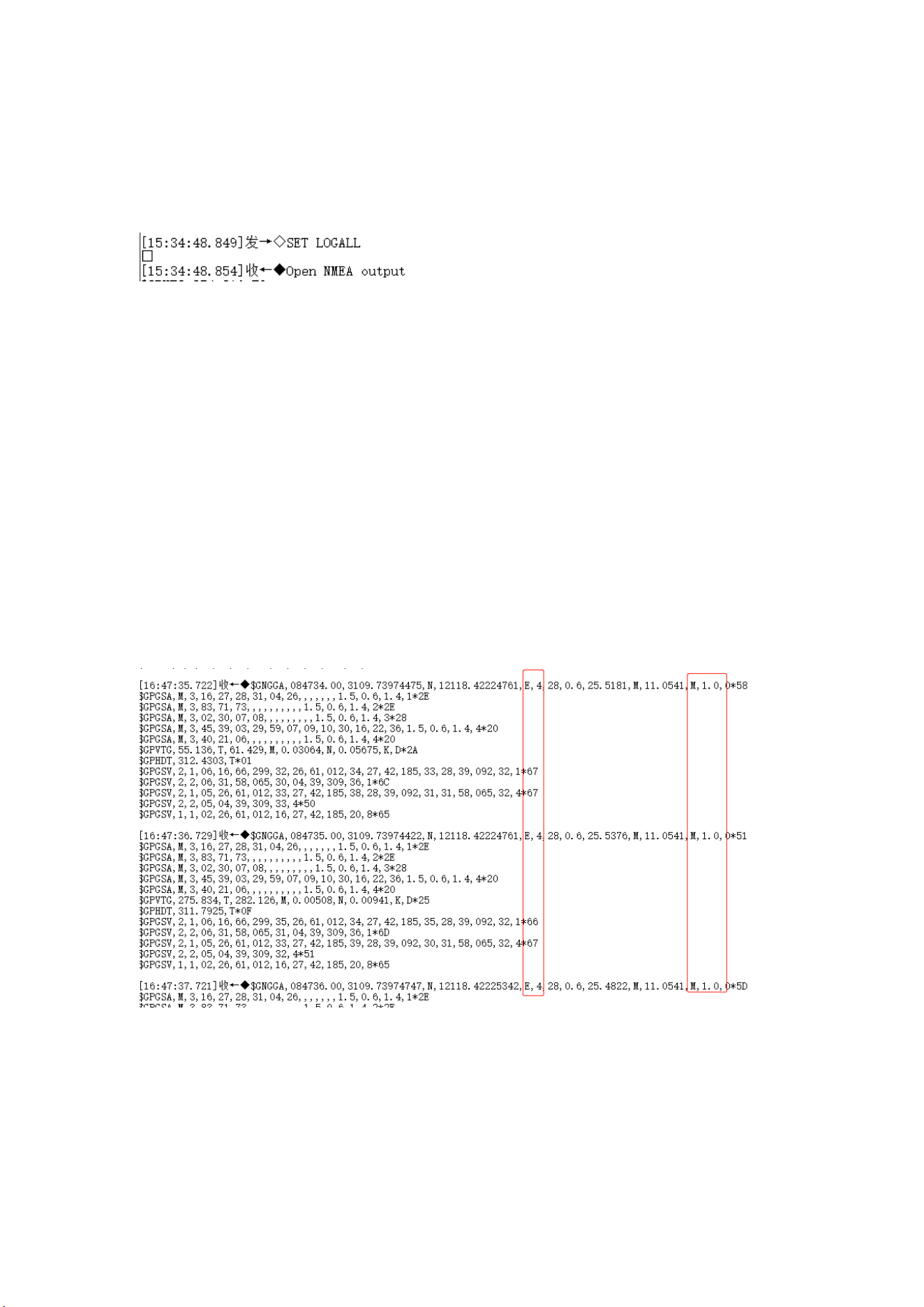
Send the GET NET to obtain the saved network configuration information, as shown
in Figure 5-11.
Address: 2nd floor, Building 1, Lane 215, Gaoguang Road, Qingpu District, Shanghai
Contact number: 021-51340805 website: www.allynav.cn
Page 2
19
Figure 5-11 Query the network configuration information
Send SET LOGALL after configuration, open GNSS and IMU output statements, and
return to the mode before shutdown, with feedback as shown in Figure 5-12.
Figure 5-12 Open the GNSS and IMU output statements
6) Set the sending command to mobile station mode and restart the receiver.
After the restart, wait to be fixed.
SYS CONFIG / / Start the configuration
SET MODE 1: / / Set up the mobile station mode
SYS SAVE / / Save the configuration / read configuration
SYS RESET / / System reboot
In Figure Figure 5-14, "E4" is fixed, and the difference delay of "M, 1.0" is
basically unchanged, and the value is very small. At this time, the serial port 2 can
output the gyro corrected data.
graph 5-14
1. Note that the instructions can be referred to Annex C in the last chapter: Commands
and messages;
2. If it is not fixed for a long time, it may be a signal problem, please place the

Address: 2nd floor, Building 1, Lane 215, Gaoguang Road, Qingpu District, Shanghai
Contact number: 021-51340805 website: www.allynav.cn
Page 2
20
receiver in an open place;
3. All instructions in the text add return replaced by default;
Appendix A:, FAQ
Appendix A introduces some common problems and possible solutions during the use
of the R73 GNSS receiver.
Problem 1: The R73 GNSS receiver could not start normally
Problem screening:
⚫ Check the polarity of the power supply;
⚫ Check whether the power cord is connected normally;
⚫ Check whether the input voltage is within the allowable range;
⚫ Check the voltage value of the cable end connector;
⚫ Check whether the power supply has a current limit;
Problem 2: The R73 GNSS receiver has no data output
Problem screening:
Check the power status of R73 GNSS receiver to ensure the receiver
Check that the required message has set the output;
Ensure that the port rate of the receiver matches the port rate of the receiving
device;
Check that the power cord and the data cable are connected normally.
Problem 3: R73 GNSS Receiver data output is scrambled
Problem screening:
Check whether the port rate of the R73 GNSS receiver is consistent with the port rate

Address: 2nd floor, Building 1, Lane 215, Gaoguang Road, Qingpu District, Shanghai
Contact number: 021-51340805 website: www.allynav.cn
Page 2
21
of the receiving equipment;
Ensure that the output message volume is less than the current set baud rate;
Problem 4: The GNSS cannot lock it up
Problem screening:
Confirm that the R73 GNSS receiver is placed in an open and unsheltered
environment;
Check the number of visible satellites and satellite SNR using UPrecise software;
Problem 5: No heading output or heading output
Problem screening:
Direction from the main antenna to the secondary antenna, the bottom arrow of
the R73 GNSS receiver should point to the bow;
Check whether there is a configured gyro output instruction;
The message output may be greater than the currently set baud rate.
Address: 2nd floor, Building 1, Lane 215, Gaoguang Road, Qingpu District, Shanghai
Contact number: 021-51340805 website: www.allynav.cn
Page 2
22
Appendix B: Technical specifications
Annex B lists the detailed technical specifications of the R73 GNSS receivers in
Appendix B
Table B-1 R73 GNSS receiver performance index
parameter
specifications
channel
1408 channel, based on the NebulasIV
signal tracing
BDS B1I/B2I/B3I /B1C/B2b
GPS L1C/A /L2P(Y)/L2C/L5
Galileo E1/E5a/E5b /E6
GLONASS G1/G2
QZSS L1C/A /L2C /L5
SBAS L1C/A
Cold start time
<30s
Initialization time
<5s (typical value)
Initialization reliability
>99.9%
Speed accuracy(RMS)
0.03m/s
Course accuracy (RMS)
<0.3°
positioning accuracy
Single Point Location (RMS):
Plane: 1.5m
Elevation: 2.5m
DGPS(RMS):
Plane: 0.4m
Elevation: 0.8m
RTK (RMS):
Level of surface: 0.8cm + 1ppm
Note 1
Elevation: 1.5cm + 1ppm
Address: 2nd floor, Building 1, Lane 215, Gaoguang Road, Qingpu District, Shanghai
Contact number: 021-51340805 website: www.allynav.cn
Page 2
23
PPP(RMS):
Plane: 5cm
Elevation: a value of 10cm
B-2 communication parameters
parameter
frequency range
4G
LTE-FDD B1/3/5/8
LTE-TDD B34/38/39/40/41
WIFI
Support for 2.4 GHz IEEE 802.11b/g/n
B-3 data communication
parameter
specifications
gorge line
2 RS-232 (1 full-duplex, one half-duplex) 1 RS-422
(half-duplex)
Baud rate
9600~460800
data format
NMEA-0183, Unicore
Data refresh rate
20HZ
networking protocol
TCP、NTRIP
B-3 Electrical indicators
parameter
specifications
working voltage
9~36V DC
power dissipation
<4W
working current
0.21A
Anti-connection
protection
have
Power lamp
1 Red
Address: 2nd floor, Building 1, Lane 215, Gaoguang Road, Qingpu District, Shanghai
Contact number: 021-51340805 website: www.allynav.cn
Page 2
24
B-4 mechanical indicators
parameter
specifications
size
634mm×165mm×94mm
weight
About 1.5kg
data transmission
interface
18-pin
gyroscope
Provide heading information
B-5 Environmental indicators
parameter
specifications
working temperature
-45℃~+75℃
Storage temperature
-55℃~+85℃
levels of protection
IP67
Address: 2nd floor, Building 1, Lane 215, Gaoguang Road, Qingpu District, Shanghai
Contact number: 021-51340805 website: www.allynav.cn
Page 2
25
Appendix C: commands and messages
Appendix C describes the common commands and messages for R73 GNSS receivers.
Please refer to the serial port instructions in the table below.
(1)String command
Table C-1, serial port command
order
description
SYS CONFIG
Unlock configuration. The SET command must have the
command unlocked, such as:
SET MODE
SYS SAVE
Lock the configuration and save the current configuration,
save the power without loss.
GET MODE
Get the working mode configuration help information
SET MODE x
Set working mode, x: Working mode to be set, available via
GET
MODE to get help information
mode declaration:
Mode 0: Pass-through configuration mode. For the
configuration of various modules and upgrade firmware;
Mode 1: Mobile station mode;;
Mode 2: manually set the reference station;
Mode 3:60S automatic positioning reference station mode;
Mode 4: Monitoring mode;
Mode 5: Static recording mode.
GET CONCOM
Get the pass-through configuration help information
SET CONCOM xx
Set up the through channel, xx: through channel, can pass
GET CONCOM
The Command Help information.
SYS RESET
System restart
SYS UPDATE
EC600 Firmware upgrade
GET NET
Gets the saved network configuration information

Address: 2nd floor, Building 1, Lane 215, Gaoguang Road, Qingpu District, Shanghai
Contact number: 021-51340805 website: www.allynav.cn
Page 2
26
GET DIFFSRC
Get the differential source configuration help information
SET DIFFSRC x
Set up the differential data source, through the GET
DIFFSRC, to obtain the configuration help letter
breath
SET IPMODE x,y
Set a certain road ip transmission mode
X: A certain road, ip
The y: Transport mode (1. TCP _ Client 2.
Ntrip _ Client 3. Ntrip _ Server)
SET IPADDR x,y,z
Set an ip information
X: A certain road, ip
y:IP address
Z: Port number (be omitted)
GET SIM
Get the SIM configuration help information
SET SIM x
Set the SIM where two SIM cards can be switched by this
command.
And x: 1,2 represent, respectively, SIM1, SIM2
SET BAUD x,bps
Set a specific baud rate, x: channel (0-3), bps: specific baud
rate
Example: SET BAUD 0,38400 (set the station Baud rate)
LOG LOGLIST
View the motherboard configuration statement information
LOG VERSION
Version and authorization information
FRESET
Clear card data
SAVECONFIG
Save motherboard instructions
AT+SAVE
Save gyro statements
AT+SETNO
Turn off all the top statements
SET UNLOG
Go to Configuration mode (GNSS statement and IMU
statement configuration before emptying)
SET LOGALL
Turn on the output statement
SET UART x, bps
Set serial port 1 or serial port 2 baud rate, x: channel (1-2),
bps: specific serial port baud rate, example: SET UART
1,38400 (set serial port 1, serial port baud rate is 38400)

Address: 2nd floor, Building 1, Lane 215, Gaoguang Road, Qingpu District, Shanghai
Contact number: 021-51340805 website: www.allynav.cn
Page 2
27
Address: 2nd floor, Building 1, Lane 215, Gaoguang Road, Qingpu District, Shanghai
Contact number: 021-51340805 website: www.allynav.cn
Page 2
28
Chapter 6 WEBUI Web page Configuration
6.1 Log in to the WEBUI
Receiver WEBUI web page configuration, mainly through the receiver
configuration. Users can connect the WiFi wireless signal sent by the receiver through
a mobile phone or computer, enter the IP address in the open browser, enter the
receiver web page configuration interface, and realize the configuration of the
receiver.
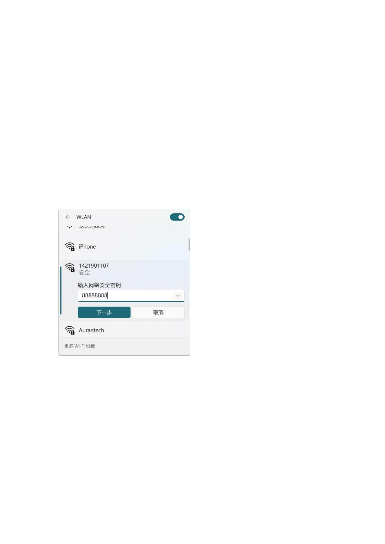
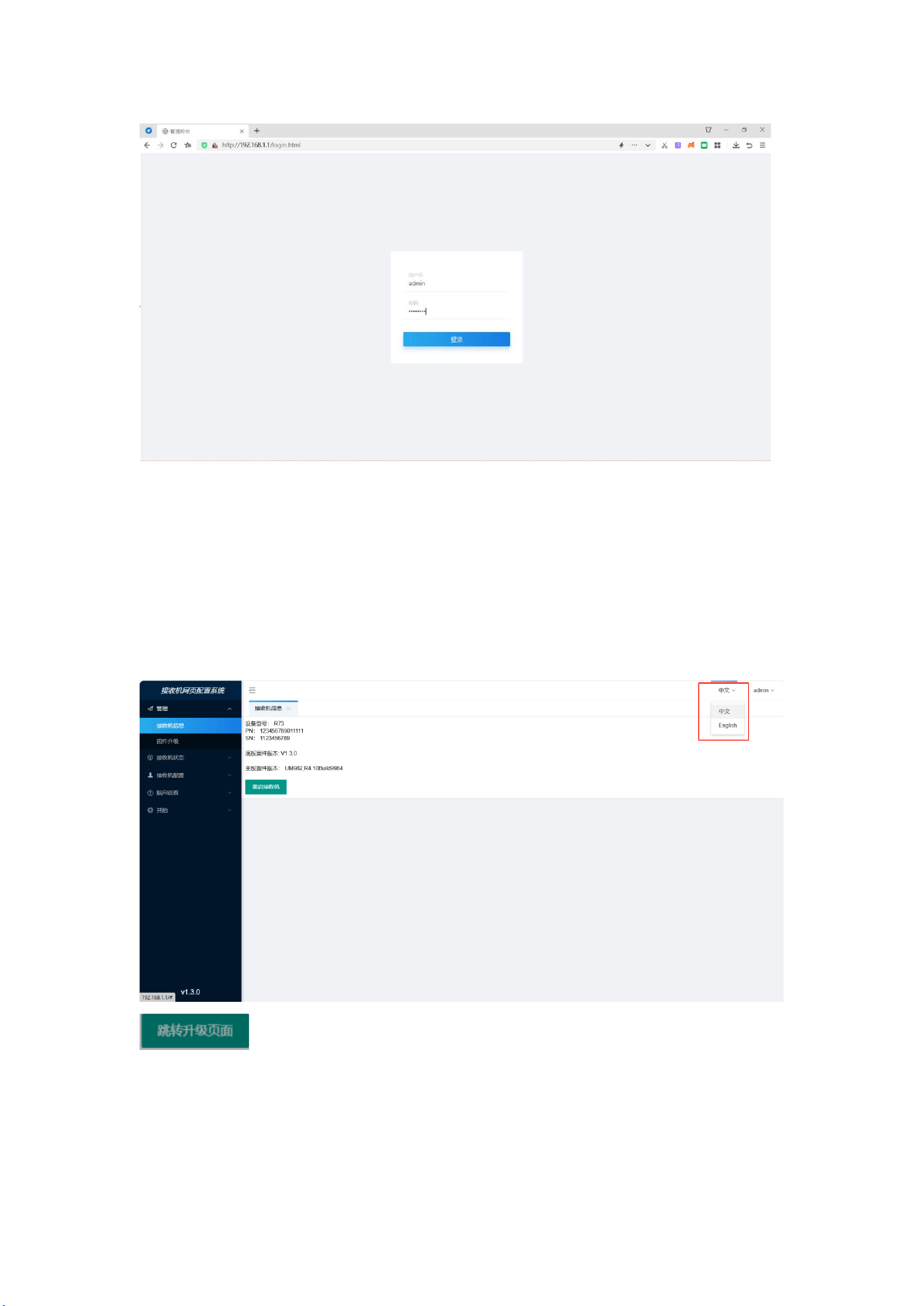
1) Open the device WIFI switch, search the device SN number, connect the WIFI,
password 88888888.
2) After connecting to the receiver through WIFI, enter the IP address (192.168.1.1) in
the browser and then enter the login interface. Account number: admin password:
88888888 Click Login to enter the receiver configuration interface.
Address: 2nd floor, Building 1, Lane 215, Gaoguang Road, Qingpu District, Shanghai
Contact number: 021-51340805 website: www.allynav.cn
Page 2
29
6.2 Receiver information
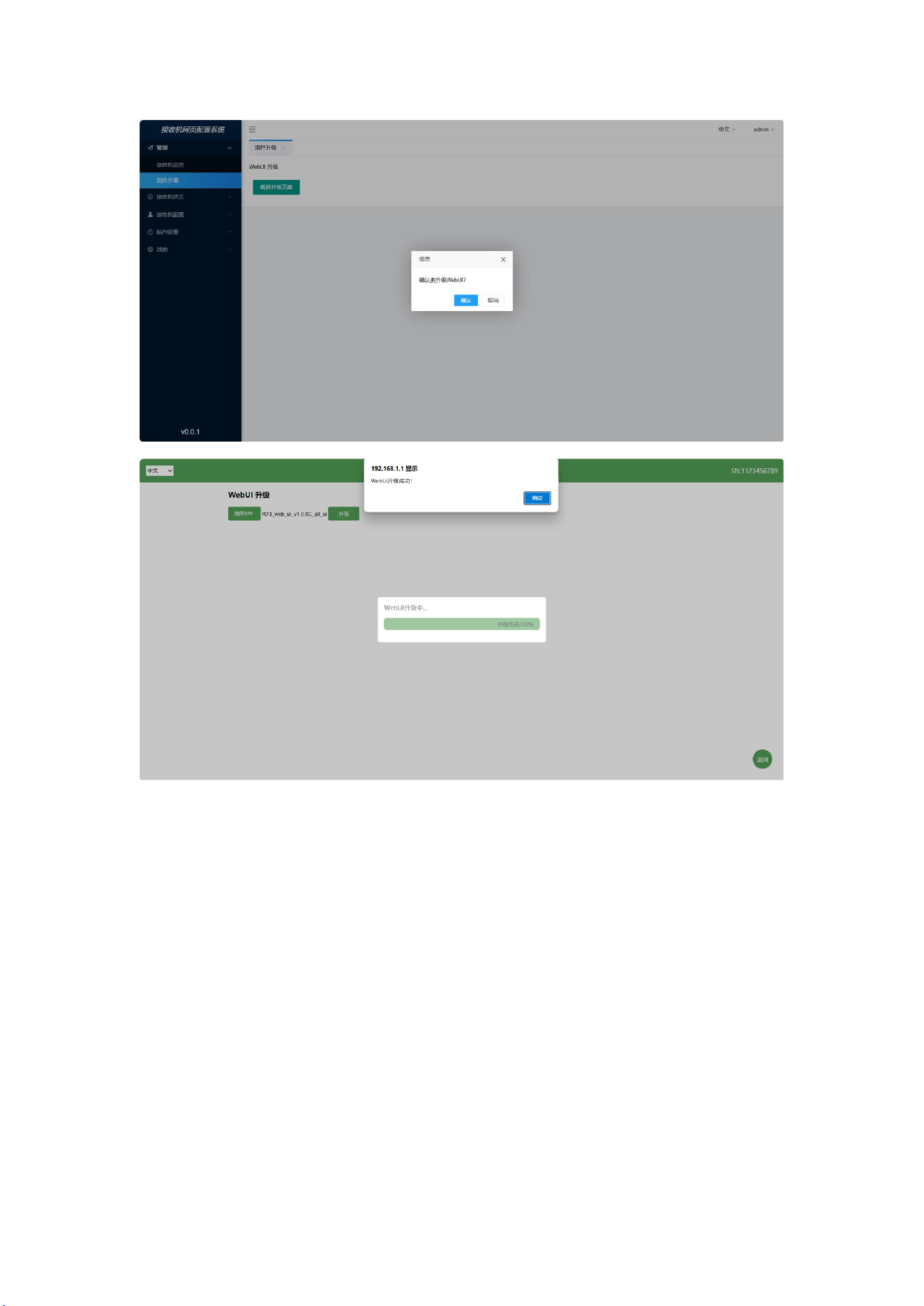
1) Chinese / English languages.
2) Display the hardware parameters information of the connected receiver, restart the
receiver, and upgrade the web page function.
3) Firmware upgrade, click, click confirm upgrade, select WEBUI
firmware click upgrade, upgrade complete click confirm, return to the refresh page.
Address: 2nd floor, Building 1, Lane 215, Gaoguang Road, Qingpu District, Shanghai
Contact number: 021-51340805 website: www.allynav.cn
Page 2
30
6.3 Receiver status
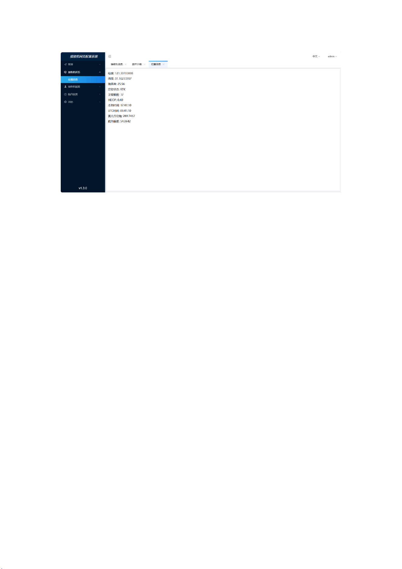
1) Location information: display the receiver's current longitude, latitude, high
altitude, difference state, number of satellites, HDOP, UTC time, true north azimuth,
and heading deviation.
Address: 2nd floor, Building 1, Lane 215, Gaoguang Road, Qingpu District, Shanghai
Contact number: 021-51340805 website: www.allynav.cn
Page 2
31
6.4 Receiver configuration
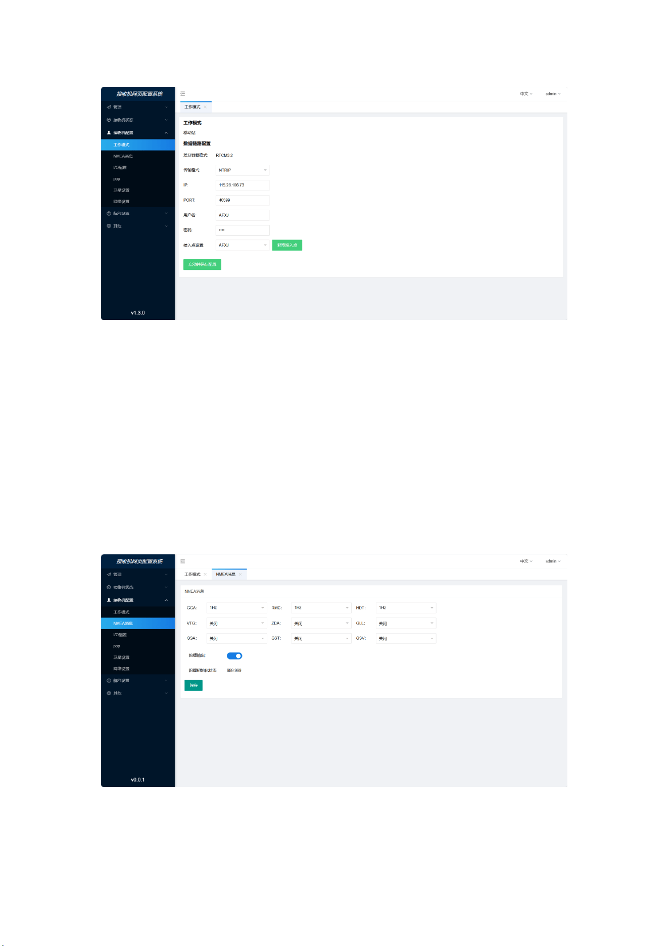
6.4.1 Working mode- -mobile station configuration
Differential format: RTCM 3.2
Transmission protocol: There are two communication protocols: NTRIP and TCP,
and the default is NTRIP protocol.
TCP setting: the server IP, enter the address of the server IP; the port number sets the
base station port number.
NTRIP setting: Set IP, port, user name, password, and access point setting click to get
the access point column. Select after the table.
Address: 2nd floor, Building 1, Lane 215, Gaoguang Road, Qingpu District, Shanghai
Contact number: 021-51340805 website: www.allynav.cn
Page 2
32
6.4.2NMEA message
1) NMEA statement and frequency configuration, support GGA, RMC, HDT, VTG,
ZDA, GLL, GSA, GST, GSV statement, support up to 20Hz, users can configure
according to the actual use requirements.
2) Gyro output: default output GNSS card data. After the IMU switch is opened, the
gyroscope heading accuracy is displayed, 999.999 is not initialized, and the serial port
1 and 2 output the IMU filtered data.
Address: 2nd floor, Building 1, Lane 215, Gaoguang Road, Qingpu District, Shanghai
Contact number: 021-51340805 website: www.allynav.cn
Page 2
33
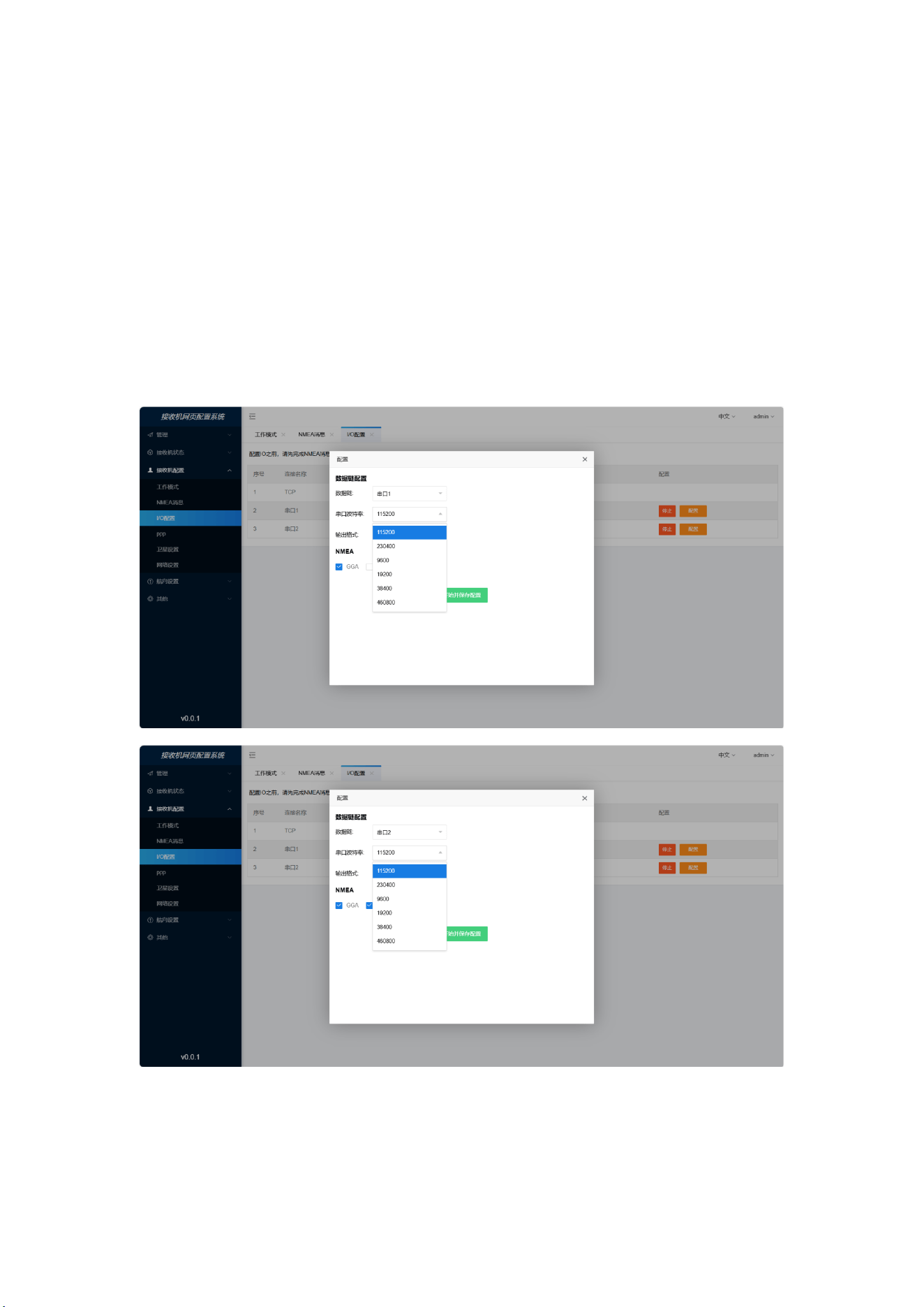
6.4.3 I / O configuration
Data chain serial port 1 and port 2
Serial port rate: select 9600,19200,38400,115200,230400,460800
Output format: NMEA-0183 statement
NMEA: Before configuring I / O, the NMEA statement information is displayed in IO,
and the NMEA-0183 statement output of each serial port can be selected according to
the requirements.
Address: 2nd floor, Building 1, Lane 215, Gaoguang Road, Qingpu District, Shanghai
Contact number: 021-51340805 website: www.allynav.cn
Page 2
34
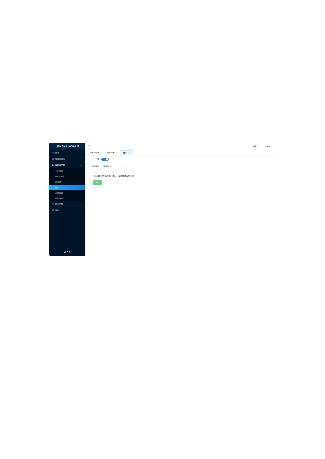
6.4.4 PPP
1) Open the precision single-point positioning of PPP-B2b and PPP-E6Has.
pay attention to:
1. B2B and E6, the function is one choice, that is, the board sets B2B and then E6,
and the output of the card is the coordinate of E6;
2. SBAS can be opened by default, set B2B or E6, and output the solution coordinates
of B2B or E6 first.
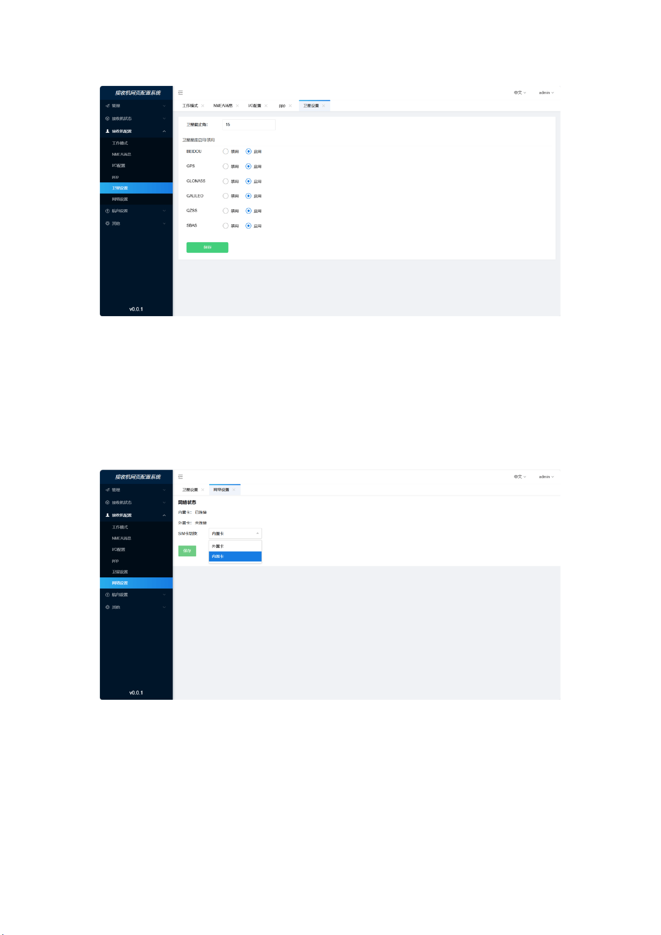
6.4.5 Satellite Settings
1) Satellite cut-off angle: the cut-off angle of the receiver can be set, and the default is
an integer with an input range of 0-90.
2) Satellite Settings: Satellite systems that can be enabled or disabled are all enabled
by default.
Address: 2nd floor, Building 1, Lane 215, Gaoguang Road, Qingpu District, Shanghai
Contact number: 021-51340805 website: www.allynav.cn
Page 2
35
6.4.6 Network Settings
1) Network status: display the network connection status of the internal card / external
card.
2) Switch between built-in cards / external cards.
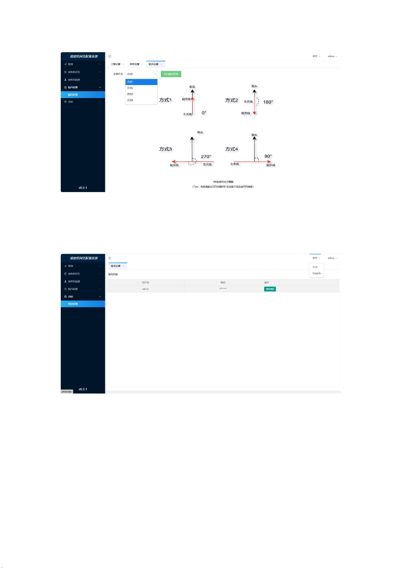
6.5 Course setting
1) Select the corresponding installation Angle for heading correction;
Note: Start the power off and restart after setting the installation direction.
Address: 2nd floor, Building 1, Lane 215, Gaoguang Road, Qingpu District, Shanghai
Contact number: 021-51340805 website: www.allynav.cn
Page 2
36
6.6 Password modification
1) Change the password of the login WEBUI web page.

Address: 2nd floor, Building 1, Lane 215, Gaoguang Road, Qingpu District, Shanghai
Contact number: 021-51340805 website: www.allynav.cn
Page 2
37
FCC Statement
This device complies with part 15 of the FCC Rules. Operation is subject to the following two
conditions: (1) This device may not cause harmful interference, and (2) this device must accept
any interference received, including interference that may cause undesired operation.
Caution: Any changes or modifications to this device not explicitly approved by manufacturer
could void your authority to operate this equipment.
NOTE: This equipment has been tested and found to comply with the limits for a Class B digital de
vice, pursuant to part 15 of the FCC Rules. These limits are designed to provide reasonable protec
tion against harmful interference in a residential installation. This equipment generates uses and
can radiate radio frequency energy and, if not installed and used in accordance with the instructi
ons, may cause harmful interference to radio communications. However, there is no guarantee th
at interference will not occur in a particular installation. If this equipment does cause harmful int
erference to radio or television reception, which can be determined by turning the equipment off
and on, the user is encouraged to try to correct the interference by one or more of the following
measures:
• Reorient or relocate the receiving antenna.
• Increase the separation between the equipment and receiver.
• Connect the equipment into an outlet on a circuit different from that to which the receiver is
connected.
• Consult the dealer or an experienced radio/TV technician for help.
Important Note:
Radiation Exposure Statement
This equipment complies with FCC radiation exposure limits set forth for an uncontrolled
environment. This equipment should be installed and operated with minimum distance 20cm
between the radiator and your body.