Guangzhou TokSurvey Information Technology Co.,ltd Guangzhou TokSurvey Information Technology Co.,ltd
.toknav.cn

Copyright © TokSurvey Information
Technology Co., Ltd. 2025. All rights
reserved.
No part of this document may be reproduced or
transmitted in any form or by any ways without prior written
consent of TokSurvey Information Technology Co., Ltd.
Trademarks and Permissions
and other TokNav trademarks are trademarks of
TokSurvey Information Technology Co., Ltd.
All other trademarks and trade names mentioned in this
document are the property of their respective holders.
Notice
The purchased products, services and features are
stipulated by the contract made between TokNav Information
Technology and the customer. All or part of the products,
services and features described in this document may not be
within the purchase scope or the usage scope.
The information in this document is subject to change
without notice. Every effort has been made in the preparation
of this document to ensure accuracy of the contents, but all
statements, information, and recommendations in this
document do not constitute a warranty of any kind, express or
implied.
Notice: The contents here are special operations and need
your specialattention. Please read them carefully.
Warning: The contents here are generally very important
as the wrongoperation may damage the machine. This can lead
to the loss of data, or evenbreak the system and endanger your
safety.
In some countries or regions, the conguration
(tuning/debugging) of devicesoperating in the EN 300 113
V3.1.1 standard 410-470 MHz band may berestricted by law.
Users must ensure compliance with local laws and
regulationsbefore operation.

Contents
1. T50 Overview -------------------------------- 01
1.1 Appearance --------------------------------- 01
1.2 Battery Indicator ----------------------------- 02
1.3 Power On and Off ---------------------------- 03
1.4 Insert a SIM Card----------------------------- 04
1.5 Charging------------------------------------ 04
1.6 Packing List --------------------------------- 05
2. WEB UI--------------------------------------- 07
2.1 System View -------------------------------- 08
2.2 Device Firmware ---------------------------- 09
2.3 Skyplot ------------------------------------- 10
2.4 Data Stream -------------------------------- 12
2.5 Mode Cong -------------------------------- 15
2.6 Others Cong ------------------------------- 17
2.7 File----------------------------------------- 18
2.8 Log ---------------------------------------- 19
2.9 Message Text ------------------------------- 19
2.10 Data Cong -------------------------------- 23
2.11 ZXVPN------------------------------------- 27
3. tSurvey2.0 Basic Operations---------------- 27
3.1 Software Installation and Uninstallation--------- 27
3.2 Project Manager----------------------------- 28
3.3 Communication ----------------------------- 29
3. 4 Rover Mode Setting ------------------------- 31
3.5 Base Mode Setting--------------------------- 36
3.6 Static Mode Setting-------------------------- 39
3. 7 Point Survey -------------------------------- 40
3.8 Tilt Survey ---------------------------------- 45
3.9 Laser Survey -------------------------------- 46
3.10 Point Stakeout ----------------------------- 48
3.11 AR Stakeout (Communication
mode needs to select WIFI) ---------------------- 51
3.12 Localization -------------------------------- 54
3.13 Calibrate Point ----------------------------- 56
3.14 Coordinate Point library --------------------- 58
3.15 Export File --------------------------------- 60
3.16 Device Information ------------------------- 61
4. Device Activation and Software Registration -- 61
4.1 Device Activation ---------------------------- 61
4.2 Software Registration ------------------------ 62
5. Built-in Radio -------------------------------- 63
5.1 Radio Protocol------------------------------- 63
5.2 Default Channel Frequency------------------- 64
6. Technical Indicators ------------------------ 65
Indicator Light
NFC
1. T50 Overview
T50is a full-featured GNSS receiver designed for long
battery life and high precision. It includes an advanced
positioning module supporting full-system and
multi-frequency satellite signal tracking. Equipped with 4G
universal connectivity, Bluetooth, WiFi, a 1.5W data radio,
and a large-capacity battery, it can operate continuously for
up 16h on a single charge. The device integrates a
high-precision inertial navigation system combined with AR
and laser camera technology for AR stakeout and laser
measurement, and augmented reality plotting, making
surveying tasks more ecient and convenient.
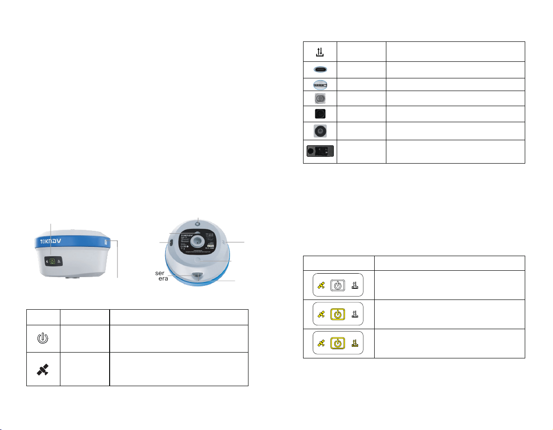
1.1 Appearance
T50 is as follows:
1.2 Battery Indicator
Press the power button for one second when the device
is off; and the battery level can be informed based on the
quantity of lights on.
01 02
Laser
Camera
project Function
Power Button
Function or status
Indicator Lights Battery level
0 % - 33%
34 % - 66 %
67 % - 100 %
FunctioBrief press for 1s to display the battery level;
Long press for 3s to turn on the device when it is off;
Long press for 3s to turn off the device when it is on.n or status
Differential Light
USB interface
Rover mode: Blink when receiving differential data;
Base mode: Blink when sending differential data.
Type-C interface, supports PD fast charging up to 33W,
please refer to 1.5.
SIM Card Slot
External SIM card, supports 4G full network access.
UHF antenna
interface
AR Camera
Laser Camera
Laser
Built-in radio: supports low (0.5W)
and high power (1.5W) options.
Professional ultra-wide-angle camera which provides high-
denition real-scene stakeout.
HD camera for tracking laser
Millimeter-level laser ranging module, integrated with high-
precision inertial navigation, and enables measurement at
anytime and anywhere.
Satellite Light
Rover/base station: 1 second interval ashing in the
positioning state;
when not searching for satellites, the light goes out;
Static mode: ashes at intervals based on the sampling frequency.
AR
Camera
Type-C
Radio
SIM Card Slot
Bellmouth
Laser
1.3 Power On and Off
Power On: In the power-off state, press and hold the
power button for 3 seconds until you hear the voice prompt
“waiting to start.” Release the power button and wait for the
panel indicator light to stop ashing alternately. Once you
hear the voice prompt “communication connection
successful,” the device has completed the power-on
process.
Power Off: In the power-on state, press and hold the
power button for 3 seconds until you hear the voice prompt
"Power off." Wait for all the panel indicator lights to go out,
indicating that the device has completed the power-off
process.
Forced Shutdown: In case of unexpected malfunction,
press and hold the power button for 10 seconds, and the
device will shut down automatically.
1.4 Insert a SIM Card
The device supports network working mode, a 4G full
network solution based on the Linux platform, and fully
supports China Mobile/China Unicom/China Telecom
2/3/4G networks, with better compatibility, stronger signals
and more stable connections.
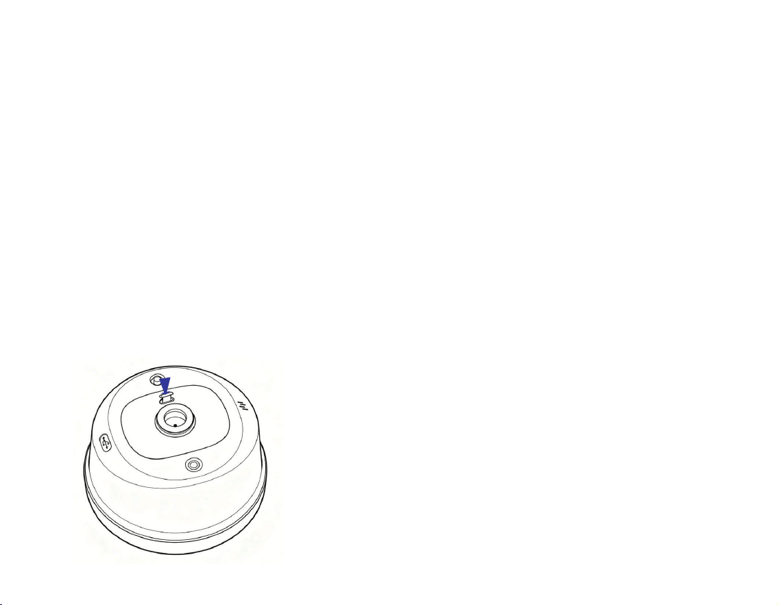
How to insert a SIM card?
1. Open the rubber cover;
2. Insert the SIM card into the slot according to the
instructions (chip facing the connector and notch facing the
slot);
3. Put on the rubber cover.
1.5 Charging
The device comes with a Type-C charger that supports
up to 33W PD fast charging. The battery can be fully
charged in just 4 hours. And the battery indicator light
shows:
Red light: The battery is charging;
Green light: The battery is fully charged.
Battery charging: Open the rubber cover, connect one
end of the data cable to the Type-C port and the other end
to the charger.
Note: For the safety of your device, please use the
adapter that comes with the package or a brand adapter that
complies with 3C certication for charging.
03 04
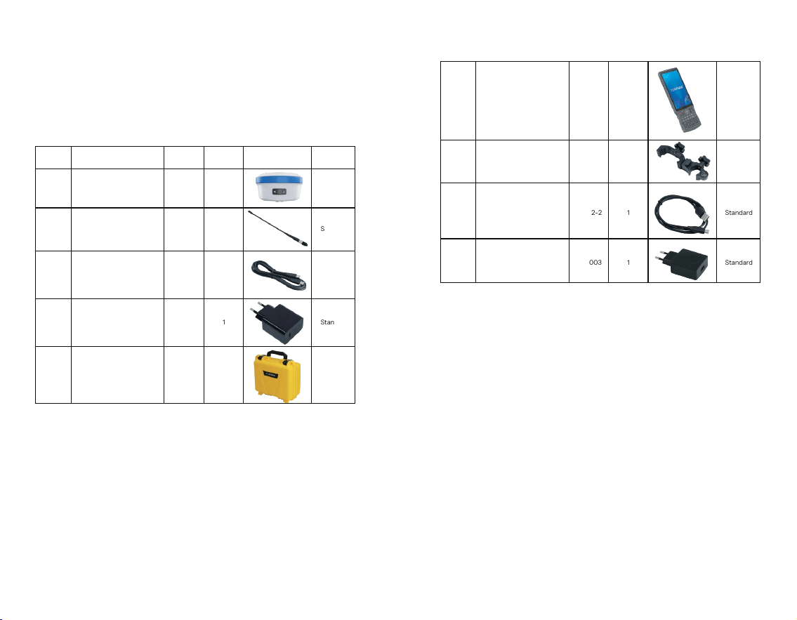
1.6 Packing List
After receiving and unpacking the package, please
check whether the device and all accessories are complete
according to the following table.
05 06
Serial
number
1
2
name model quantity
1
1
Geodetic GNSS Receiver
450-470M Radio Antenna
T50
AT0038
Standard
Standard
3
1CC Data Cable L0602-1
Standard
4
1
33W PD Power Adapter
CG0004
Standard
5
1
T50 yellow PP box packaging
Standard
picture Remark
1Type-C Data Cable L0602-2
Standard
1
5V/2V USB Power Adapter
CG0003
Standard
6
1
PCR100T
BB0036
Optional
7
8
9
1
P9N controller bracket
BB0037
Optional
2. WEB UI
The device WIFI can be used as a hotspot, which can be
connected with a PC, smartphone or tablet. After
connecting to the hotspot, you can log in to the device’s
Web UI Manage work status, change work mode, modify
basic settings, download raw data, update rmware, and
register devices, etc.
Taking your computer's interface as an example, enter
the Web UI and do the following:
1. Use a computer to nd and connect to the device's
WIFI hotspot. Hotspot name: device serial number, and the
default password is empty.
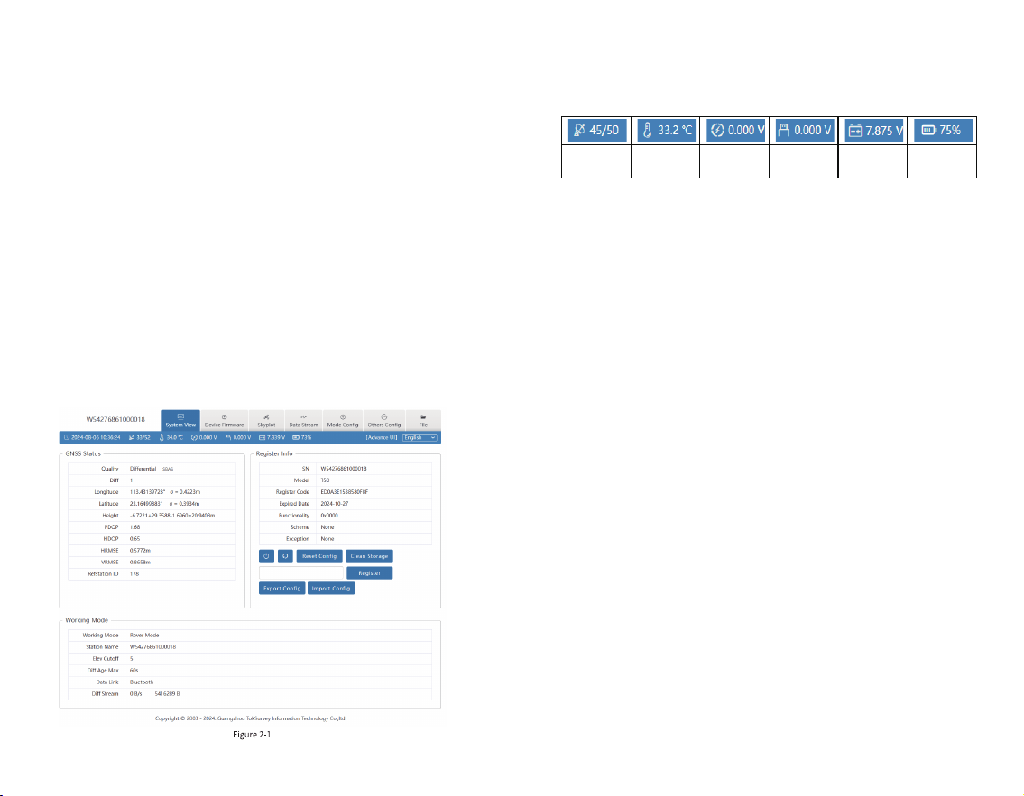
2. Open the web browser and input the IP address
10.10.10.10. The interface is shown in Figure 2-1.
3. Meaning of icons arranged horizontally above the
interface:
2.1 System View
① GNSS Status: Quality, diff, Longitude, latitude,
Height, accuracy, Ref station ID;
②Register info: SN, Model, Register Code, Expired
Date, Functionality, Scheme, Exception;
③Working mode: working mode, Station name, Elev
cutoff, Diff Age Max, Data Link, Diff Stream.
④ Device Operation:
1) System command: shut down and restart the device
2) Conguration and data: reset conguration, clean
storage, export conguration, and import conguration;
3) Registration code: The registration code is a valid
time code that authorizes the device positioning function.
When the registration code is found to have expired and the
device positioning function is unavailable, you can obtain a
new registration code from the supplier by providing the
device number, enter it into this page, and click [Register] to
register. The page effect is shown in Figure 2.1-1.
07 08
Satellite
Used/Tracked
Temperature
Extended
Voltage
Supply Voltage
Battery Voltage
Battery Info
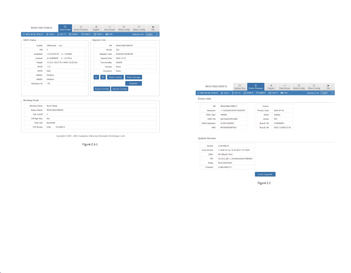
2.2 Device Firmware
The device rmware displays the Device Info, System
Version and a local upgrade button, as shown in Figure 2.2.
①Device Info: SN, Hardware, GNSS Type, GNSS SN,
GNSS Hardware, IMEI, Feature, Product Date, Brand, Model,
and Board SN.
② System Version: system, Linux Version, positioning
board, tilt module, radio rmware version, device rmware
version.
Click the local upgrade below to automatically identify
the positioning board rmware, tilt module rmware and
device rmware that need to be upgraded. The specic
steps are as follows:
2.3 Skyplot
This diagram mainly displays satellite tracks and
satellite status diagrams, for example, traces, satellite lists,
status, etc., as shown in Figure 2.3-1:
1. Click [Local Upgrade];
2. Select the correct device rmware in the pop-up
window, upload the rmware and wait for the device to
restart;
3. After the restart is completed, the rmware upgrade
is completed;
4. Reconnect the device to WIFI, enter the WEB UI, and
check whether the rmware is upgraded successfully.
09 10
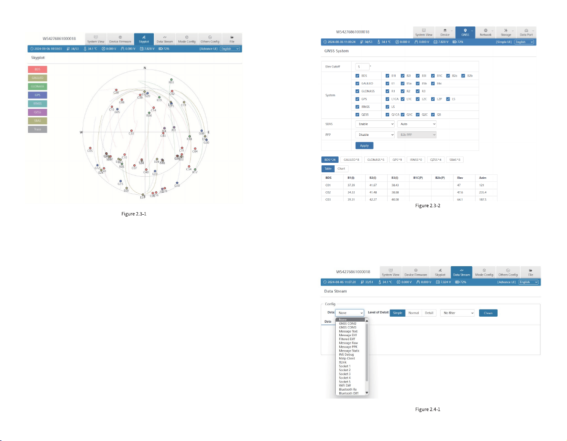
2.4 Data Stream
Data stream is mainly used to debug data information.
You can view the status of current data, as shown in Figure
2.4-1:
① GNSS System: Elev Cutoff: Set the Elev Cutoff;
② Satellite List: There are many satellite systems
available, such as BDS, GALILEO, GPS, GALONASS, etc. If
you nd that the device receives fewer satellites under
normal conditions, you can enter the page to check whether
all satellite systems are turned on, click the small box at the
back to turn on/off the corresponding satellite system.
③ SBAS: Choose to turn on or off the satellite-based
augmentation system;
④ PPP: Select to disable or enable PPP mode, as shown
in Figure 2.3-2
11 12
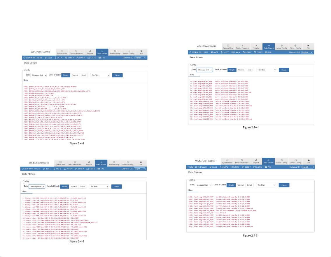
For example:
1.Message Text: see 2.9 in this Section for the
conguration of message text, and the output is shown in
Figure 2.4-2:
2.Message Raw: as shown in Figure 2.4-3:
3.Message Diff: when the device is a base station, you
can check here whether there is differential data output, as
shown in Figure 2.4-3:
4. Message Static: When the device is in static mode,
you can check here whether there is static data output, as
shown in Figure 2.4-5:
13 14
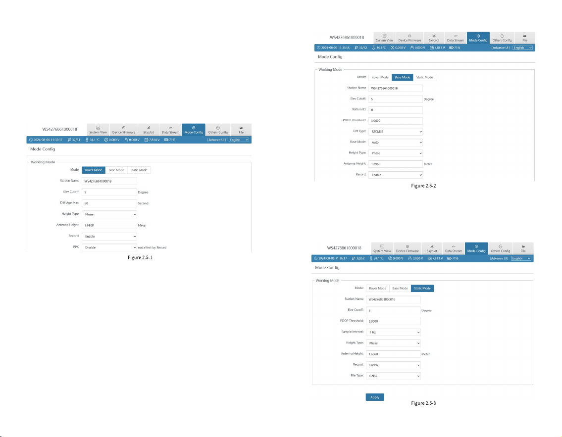
2.5 Mode Cong
① Working mode: You can select Rover Mode/ Base
Mode/Static Mode, and select the Elev Cutoff at the same
time;
1. Rover Mode: the following parameters (Station Name,
Elev Cutoff, Diff Age Max, Height Type, Antenna Height,
Record, PPK) can be congured, as shown in Figure 2.5-1:
2. Base Mode: You can congure parameters (Station
Name, Elev Cutoff, Station ID, PDOP Threshold, Diff Type,
Base Mode, Height Type, Antenna Height, Record), as
shown in Figure 2.5-2:
3. Static mode: the following parameters (Station
Name, Elev Cutoff, PDOP Threshold, Sample Interval,
Height Type, Antenna Height, Record) can be congured, as
shown in Figure 2.5-3:
15 16
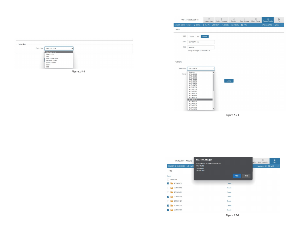
2.6 Others Cong
① WIFI: You can choose from three types: Disable/AP
/Station, and you can set the WIFI name and password by
yourself. When the device WIFI is used as the Station, you
can access the network by entering the name and password
of the external hotspot.
② Others: You can select the device’s UTC time and set
it according to your region. The interface is shown in Figure
2.6-1:
2.7 File
In this interface, you can batch delete the data folders in
the device, as shown in Figure 2.7.1; enter the le directory
and you can choose to download the data of each channel,
as shown in Figure 2.7.2.
1. Bluetooth: the device obtains the differential data of
tSurvey2.0 software accessed by the controller network
through Bluetooth connection;
2. Built-in network: the device receives or sends data
through the built-in network. To select this data link, please
insert the SIM card into the device rst;
3. Built-in Radio: the device receives data via the built-in
radio. To select this data link, please connect the radio
antenna to the device rst.
② Data link: You can choose No Data link/Bluetooth/
WIFI /Built-in Network/Built-in Radio /External radio
/XLink/PPP, as shown in Figure 2.5-4:
17 18
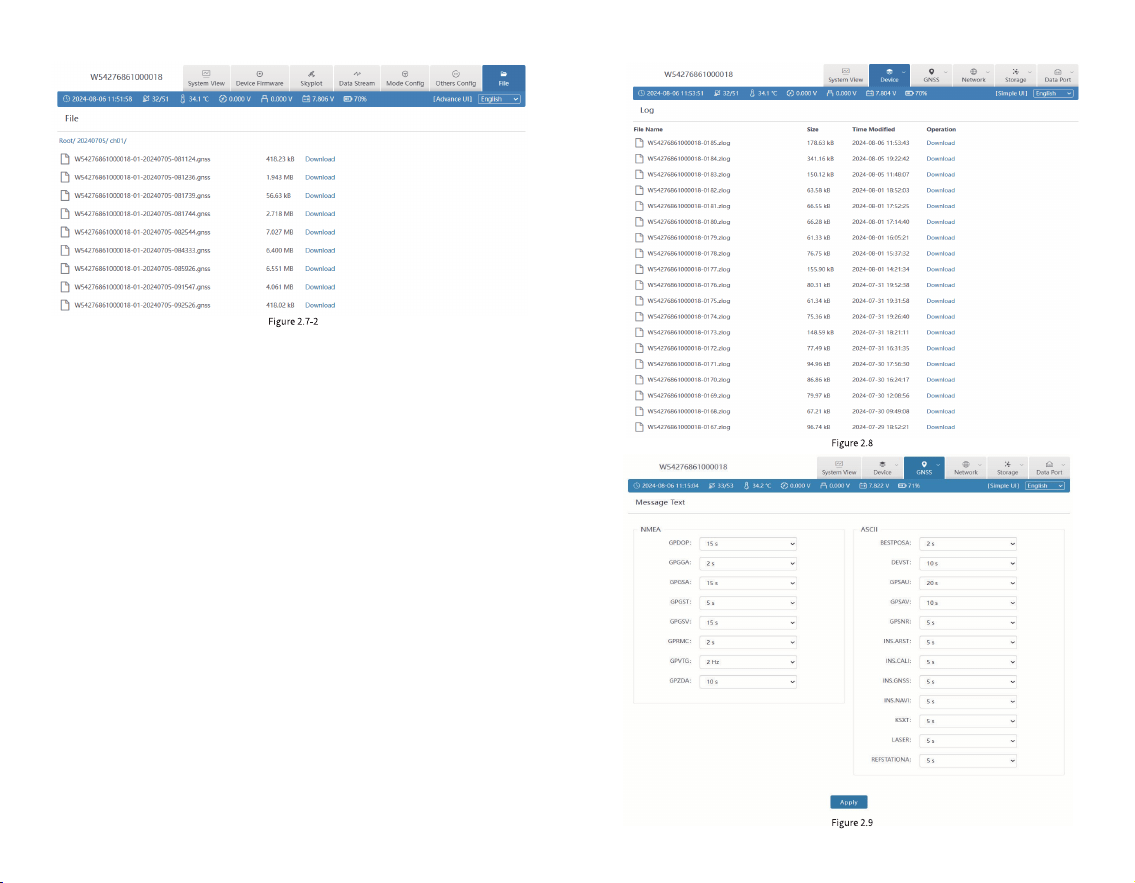
2.8 Log
It provides the download of equipment operation logs.
When an abnormality occurs during the use of the
equipment, you can download the logs generated at the
corresponding time and provide them to our company so
that we can troubleshoot the problem for you, as shown in
Figure 2.8:
2.9 Message Text
You can set the type and frequency of text format
output data, as shown in Figure 2.9. After the conguration,
you can check whether there is corresponding text data
output in 2.4 of this section.
19 20

The following are the formats of several common
message text:
$GPGGA
Example:
$GPGGA,092204.999,4250.5589,S,14718.5084,E,1,04,24.4,19.7,M,,,,0000*1F
Field 0: $GPGGA, statement ID, indicating that the statement is Global
Positioning System Fix Data (GGA) GPS positioning information
Field 2: Latitude ddmm.mmmm, in degree and minute format (if the leading
digits are insucient, ll them with 0)
Field 4: longitude dddmm.mmmm, in degree and minute format (if the leading
digit is insucient, add 0)
Field 6: GPS status, 0 = not positioned, 1 = non-differential positioning,
2 = differential positioning, 3 = invalid PPS, 6 = estimating
Field 7: Number of satellites in use (00 - 12) (if the leading digit is insucient,
ll it with 0)
Field 1: UTC time, hhmmss.sss, in hour, minute, second format
Field 3: Latitude N (North) or S (South)
Field 5: Longitude E (East) or W (West)
Field 8: HDOP horizontal dilution of precision (0.5 - 99.9)
Field 9: Altitude (-9999.9 - 99999.9)
Field 10: The height of the Earth's ellipsoid relative to the geoid
Field 13: Checksum
$GPGSV
Example: $GPGSV,3,1,10,20,78,331,45,01,59,235,47,22,41,069,13,32,252,45*70
Field 1: The total number of GSV statements this time (1 - 3)
Field 2: This GSV statement is the number of this GSV statement (1 - 3)
Field 7: Signal-to-noise ratio (00-99) dbHz
Field 3: Total number of currently visible satellites (00 - 12)
(if the leading digit is insucient, add 0)
Field 4: PRN code (pseudo-random noise code) (01 - 32)
(if the leading digit is insucient, add 0)
Field 5: Satellite elevation angle (00 - 90) degrees
(if the leading digit is insucient, ll it with 0)
Field 6: Satellite azimuth (00 - 359) degrees
(if the leading digit is insucient, ll it with 0)
Field 8: PRN code (pseudo-random noise code) (01 - 32)
(if the leading digit is insucient, add 0)
Field 9: Satellite elevation angle (00 - 90) degrees
(if the leading digit is insucient, ll it with 0)
Field 11: Signal-to-noise ratio (00-99) dbHz
Field 15: Signal-to-noise ratio (00-99) dbHz
Field 16: Checksum
Field 10: Satellite azimuth (00 - 359) degrees
(if the leading digit is insucient, ll it with 0)
Field 12: PRN code (pseudo-random noise code) (01 - 32)
(if the leading digit is insucient, ll it with 0)
Field 13: Satellite elevation angle (00 - 90) degrees
(if the leading digit is insucient, ll it with 0)
Field 14: Satellite azimuth (00 - 359) degrees
(if the leading digit is insucient, ll it with 0)
Field 0: $GPGSV, statement ID, indicating that the statement is GPS Satellites
in View (GSV) visible satellite information
Field 11: Differential time (seconds from the last differential signal received,
empty if not differential positioning)
Field 12: Differential station ID number 0000 - 1023 (if the leading digit is
insucient, it will be lled with 0, and it will be empty if it is not differential
positioning)
21 22
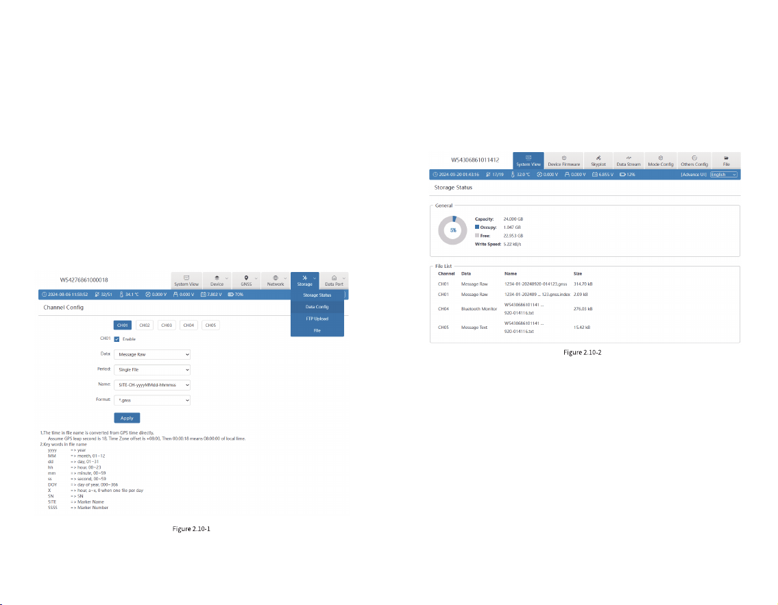
2.10 Data Cong
The device has 24G storage space (recyclable storage)
and supports ve channels (CH01/CH02/CH03/CH04/CH05)
to save various les, as shown below. We can control the
data source, le period, le name and le format of each
channel for storage as needed. The naming rules page has
detailed instructions, as shown in Figure 2.10-1.
When the device is set to rover, base or static mode, the
device will automatically control the corresponding channel
for data storage by default.
Note: Do not change the mode after the device data
conguration is completed, otherwise the default storage
conguration will be restored.
1. Rover (CH01)
When the device is set as a rover station, the device will
automatically congure CH01 to store and locate the
original data by default. If PPK is enabled, CH05 will also be
automatically congured to store the post positioning data
by default, as shown in Figure 2.10-2:
2. Base (CH02)
When the device is set as a base station, the device will
automatically congure CH02 to store and locate raw data
by default. If PPK is enabled, CH05 will also automatically
congure the storage location for post-processed data by
default, as shown in Figure 2.10-3:
23 24
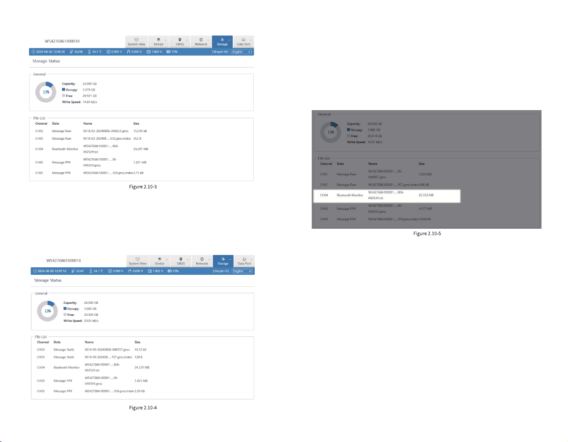
3. Static (CH03)
When the device is set to static mode, the device will
automatically congure CH03 to store static positioning
data by default, as shown in Figure 2.10-4:
Note: Whenever the tSurvey2.0 software is connected
to the device via Bluetooth, the device will automatically
congure CH04 to store Bluetooth monitor data. If there are
any problems with the settings of the Bluetooth connected
device, you can download the recorded Bluetooth monitor
data for troubleshooting, as shown in Figure 2.10-5:
25 26
3. Find the program in the le management of the
controller and install it;
4. Click on the tSurvey2.0 software on the desktop (you
need to create a project for the rst time, and the last project
used will be automatically opened each time the software is
started).
Uninstallation process:
Uninstall method: Long press the software icon on the
desktop, drag to the [ Uninstall] option box, and click " OK "
to complete the software uninstallation.
3.2 Project Manager
Click [ Project] [ Project Manager], as shown in Figure
3.2-1. Project manager includes functions such as creating a
new project, importing a project, exporting a project,
deleting a project, and opening a project.
Click [Project Path] to modify the path of the project on
disk. The default path is in the internal storage tSurvey2.0
> Project directory.
Click [Details], as shown in Figure 3.2-2, to modify the
basic properties of the project, such as Basic Information,
Coordinate system parameter, and Code Library.
Click [ New], as shown in Figure 3.2-3. To create a new
project, you need to ll in the basic properties such as
project name, whether to apply the project, and select the
coding template. Click [ OK] and ll in the coordinate system
parameters used to modify the project, as shown in Figure
3.2-4. Click [OK] to complete the creation of the project.
Click on other items in the list, and the open function will
appear, as shown in Figure 3.2-5. Long press on an item in
the list, and the delete function will appear, as shown in
Figure 3.2-6 (Note: you cannot delete a project that is in use).
3. tSurvey2.0 Basic Operations
3.1 Software Installation and Uninstallation
Installation process:
1. Download the Android tSurvey2.0 program (*.apk);
2. Copy the tSurvey2.0 program to your mobile phone
(controller);
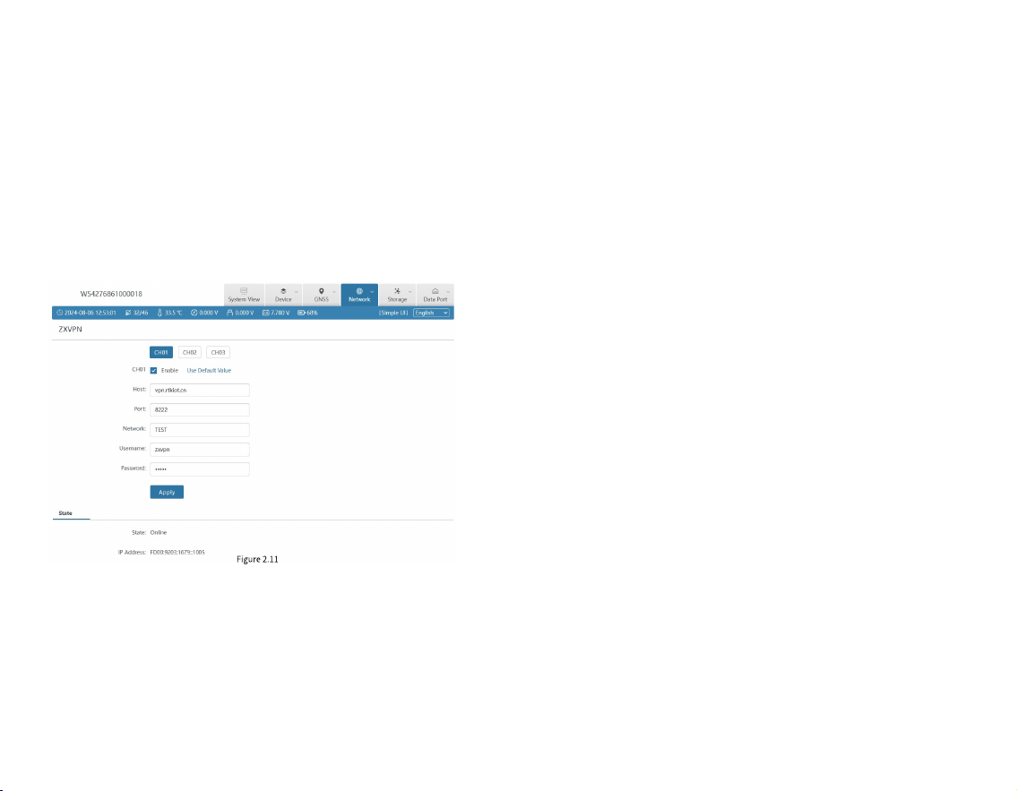
2.11 ZXVPN
ZXVPN can provide a virtual LAN, connect the device to
the server, and access the Web UI in the background,
providing corresponding remote technical support and
services. The steps are as follows:
1. Insert a SIM card into the device;
2. Turn on the mobile network and make sure it is
connected to the Internet, or connected to the WIFI;
3. Click [Use default value] to apply, as shown in Figure
2.11.
27 28
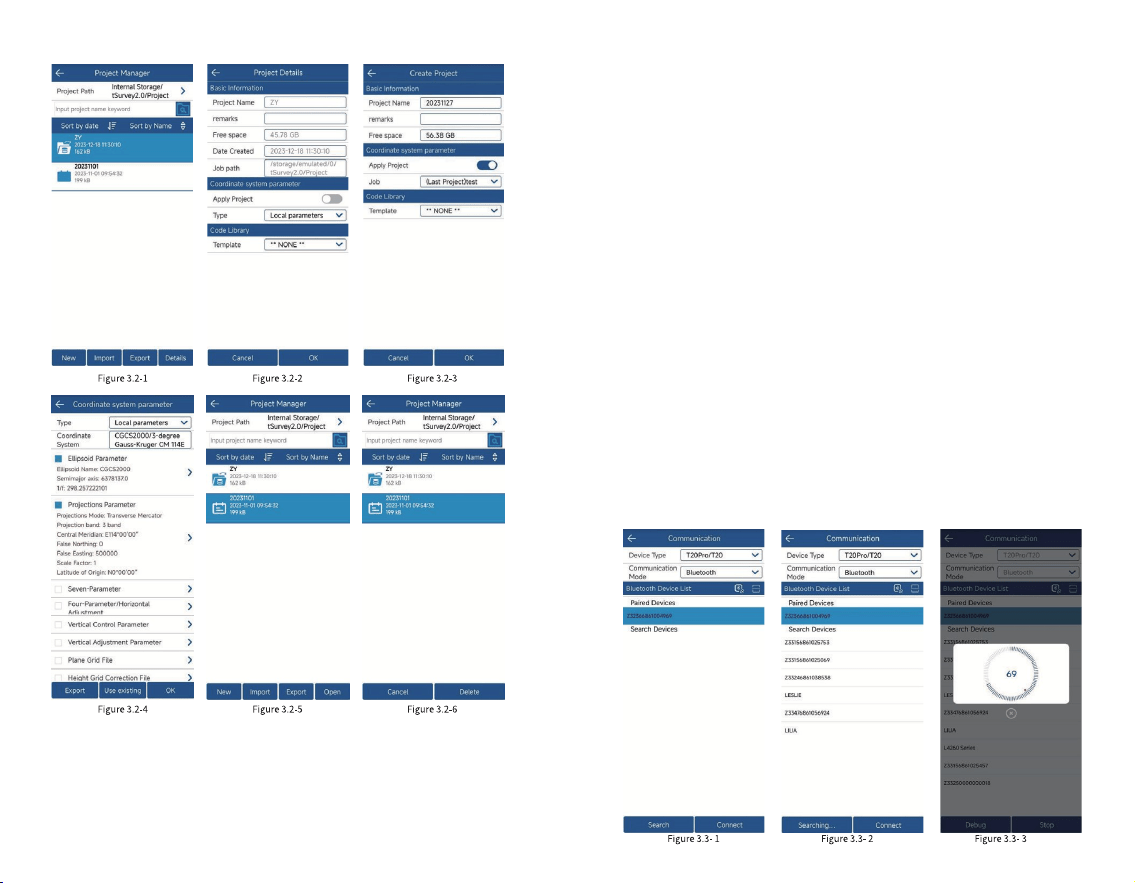
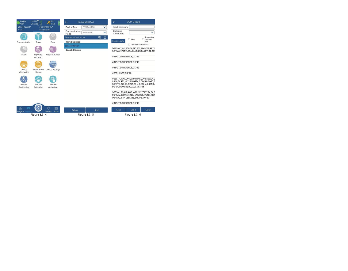
(Bluetooth), and then click [ Search], as shown in Figure
3.3-2. View the Bluetooth device list, select the
corresponding device serial number, and click [Connect] to
complete the device connection, as shown in Figure 3.3-3.
After the device is successfully connected, it will directly
return to the device interface, as shown in Figure 3.3-4.
Enter the communication settings again, as shown in Figure
3.3-5, and click [Stop] to disconnect the device. Click
[Debug] to view the data of the software and device
communication, as shown in Figure 3.3-6.
1. Communication mode includes Bluetooth, serial port,
TCP client port, etc.;
2. Click [Search] and select the device you want to
connect according to the device serial number;
3. After the device is successfully connected, click
[Debug] to view the data of communication between the
software and the device. You can also send debugging
commands to the device to troubleshoot and analyze issues
related to device positioning.
3.3 Communication
Click [Device] [Communication] to enter the
communication settings interface, as shown in Figure 3.3-1.
Select the device type (RTK), communication mode
29 30
non-xed position is called the rover. Relative to the
GNSS satellite signal of the rover, the data transmitted by
the base is called differential data, and the data transmission
method is called data link. The rover mode setting is to set
the GNSS as a rover, congure certain parameters to
transmit the GNSS satellite signal of the base station to the
GNSS device in a certain way, so that the GNSS device can
obtain a high-precision positioning.
In addition to differential data transmission
conguration, you can also set the GNSS cutoff angle,
differential delay, and whether to enable PPK and other
basic information, as shown in Figure 3.4-1. Adjust the
altitude angle to not receive the satellite signal when it is
lower than a certain value. In the case of poor satellite signals
at low angles, it is benecial to precision calculation. The
PPK parameter records the original GNSS observation data
to the GNSS receiver and uses the post-processing
algorithm to calculate high-precision coordinates.
The differential data parameter setting is mainly to set a
way to transmit the differential data of the base station to
the current device, so as to provide the necessary solution
conditions for the device to solve high-precision
coordinates. The data link methods mainly include Phone
Internet, Device Internet, Internal Radio and other methods.
1. Phone Internet: As shown in Figure 3.4-1, it refers to
obtaining differential data from the specied server address
through the network of the device where the software is
located according to a certain protocol, and then sending it
to the device through the communication connection
between the software and the GNSS device for
high-precision solution. Click on the right side of CORS
3. 4 Rover Mode Setting
Click [Device] [Rover], as shown in Figure 3.4-1.
GNSS positioning equipment can calculate positioning
coordinates by receiving satellite signals. In the absence of
other interferences, the positioning equipment can only
obtain the coordinate position of a single point solution due
to the interferences of the atmosphere on the signal, and the
accuracy is low. In order to ensure that GNSS devices can
obtain high-precision positions, in addition to the GNSS
device itself receiving satellite signals to calculate the
position, it is also necessary to receive the signal of another
nearby xed-position GNSS device, and use the signal of the
other device as the reference signal. Since the inuence of
the atmosphere on the signal is basically the same within a
certain area, when the coordinate position of the reference
signal is known, the two sets of GNSS can calculate the
high-precision position. The GNSS device with a xed
position is called the base, and the GNSS device with a
31 32
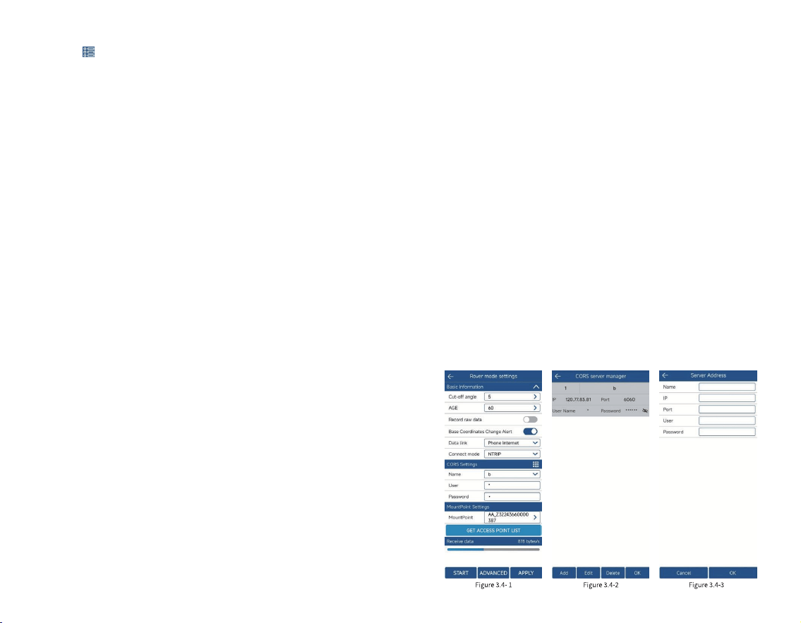
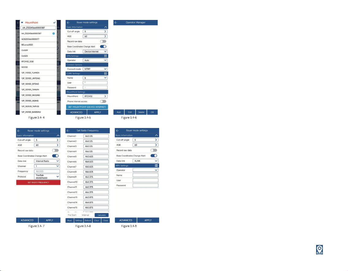
settings to enter the CORS server management interface,
as shown in Figure 3.4-2. You can directly select, edit, and
delete existing CORS servers, or manually add CORS server
parameters, as shown in Figure 3.4-3. After correctly
conguring the server address, obtain the access point list,
as shown in Figure 3.4-4, and select the corresponding
access point to obtain differential data. Click [Start], if the
conguration is correct, the data reception progress bar will
move. If there is no data in the progress bar, you need to
conrm whether the parameter conguration is correct.
2. Device Internet: As shown in Figure 3.4-5, it refers to
obtaining differential data from a specied server address
through the SIM card network of the GNSS device according
to a certain protocol for high-precision solution. The
connection mode is the transmission protocol of differential
data, usually by NRTIP, TCP client, etc., enter the server IP,
port, username and password and other connection
parameters. The SIM network is a dedicated network and
needs to congure APN parameters, as shown in Figure
3.4-6. The CORS setting is similar to the Phone Internet.
After correctly conguring the server address, obtain the
access point list and select the corresponding access point
to obtain differential data. In addition to obtaining access
points through the Device Internet, it can also be obtained
through the network corresponding to the mobile phone if
there is a mobile phone with a network.
3. Internal Radio: As shown in Figure 3.4-7, it means
receiving the differential data of the radio station according
to a certain protocol and frequency through the internal
radio of the GNSS device, and performing high-precision
calculation. At this time, it is necessary to ensure that the
protocol and frequency of the built-in radio station are
consistent with the protocol and frequency of the
transmitting radio station, so that the radio station data can
be received normally. If the frequency corresponding to the
channel is inconsistent with the channel frequency of the
transmitting radio station, you can click [Set Radio
Frequency] to modify the frequency corresponding to each
channel of the radio station, as shown in Figure 3.4-8.
4. XLINK: As shown in Figure 3.4-9, it is a differential
forwarding system built based on the CORS network of
Qianxun/ Liufen/ China Mobile. After conguring the Xlink
data link, the host can access the differential normally if it
can access the Internet, without the need for the customer
to manually ll in the CORS account.
Note: Each data link has the base coordinate change
alert turned on by default, because if the wrong base station
signal is received, the coordinates may be inaccurate,
reminding the user to check and conrm.
33 34
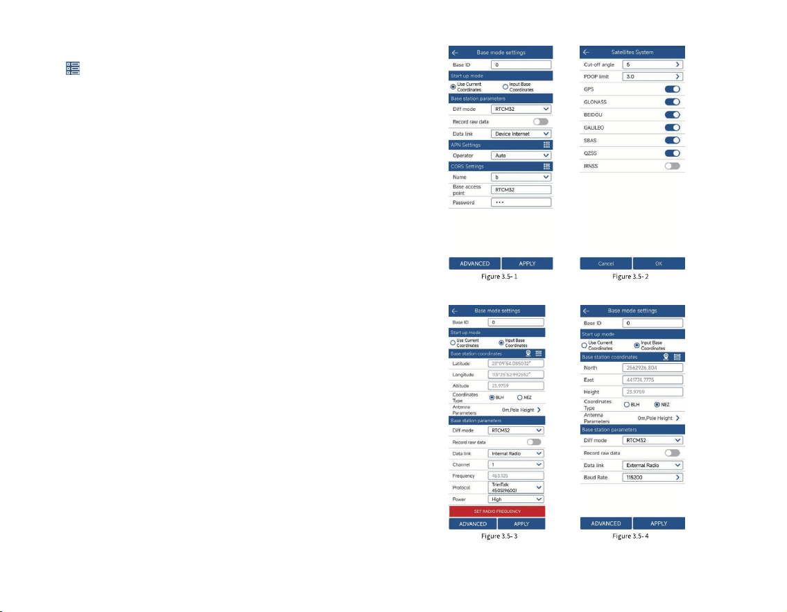
3.5 Base Mode Setting
Click [Device] [ Base], as shown in Figure 3.5-1. This
function is that the GNSS device acts as a base to send
satellite information data in a certain way and provide it to
the rover to receive it, providing it with high-precision
solution conditions. The host needs to set the startup
condition parameters, startup mode and data broadcast
parameters as a base.
Note: During the startup of the base station, the device
is not allowed to move, otherwise the coordinates calculated
by the rover will be wrong.
The start-up conditions include Base ID, Diff Mode,
cut-off angle, PDOP limit and other parameters. Click
[Advanced], as shown in Figure 3.5-2, to congure cut-off
angle, PDOP limit and other parameters. The differential
data format includes CMR, RTD, RTCM23, RTCM30,
RTCM32, RTCM33 and other commonly used differential
data encoding formats;
The startup mode includes using Current coordinates,
inputting Base coordinates, etc., among which:
1. Use Current coordinates: This means that the GNSS
device outputs differential broadcast data for the startup
coordinates based on the current positioning value (with low
accuracy);
2. Input Base Coordinates: refers to the location where
the user sets up the equipment. The user knows the
coordinates of this location in advance and uses this
coordinate value as the starting coordinate to output
differential broadcast data. Click [ Specify Base Station
Coordinates] to enter the interface for setting base station
coordinates, as shown in Figure 3.5-3. You can click the
35 36
measurement icon to measure a point in real time, or
click to select a coordinate value from the coordinate
point library.
The data broadcast parameters are mainly the
differential data output by the device after starting the base
station, which is transmitted through a certain method and
received and used by the rover. The main methods include
device Internet, built-in radio, external radio, etc. The
parameter settings are similar to those of the rover, with the
following differences:
1. The internal radio has a transmission power. The
higher the transmission power, the longer the effective
distance, and the greater the power consumption;
2. Device Internet NTRIP protocol, the base station is
the base station access point that sets the start of
transmission, as shown in Figure 3.5-1, and the rover obtains
the access point list and selects the corresponding base
station access point to connect;
3. The base station uses an external radio to broadcast
differential data, as shown in Figure 3.5-4. The baud rate
must be consistent with the connected external radio;
4. For CORS settings, refer to the rover data link for
corresponding conguration.
37 38
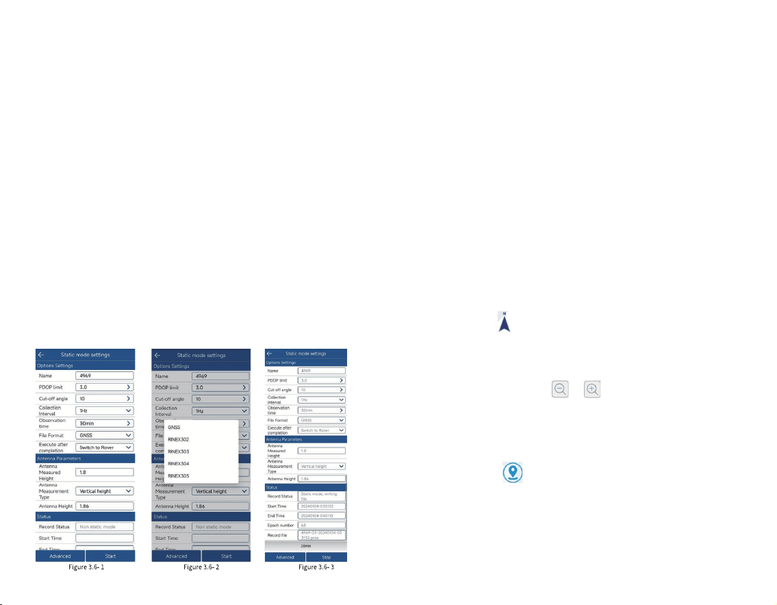
3.6 Static Mode Setting
Click [Device] [Static Mode], as shown in Figure 3.6-1.
This function is to store the original satellite observation
data of the GNSS device into the set disk le, record the
observation data of a period of time for the use of static
post-processing software to solve the high-precision
coordinate position, usually used for control point
acquisition. To start the static mode, you need to set the
static le point name, PDOP limit, cut-off angle, Collection
interval, antenna parameters and File Format and other
recording conditions, as shown in Figure 3.6-2.
Click [Start] to start static collection, as shown in Figure
3.6- 3, and click [Stop] to end static collection. The status
will display information such as Record Status, Start Time,
Epoch number, and Record le.
Note: During static recording, the device is not allowed
to move, otherwise it will cause errors in the coordinates
calculated by post-processing.
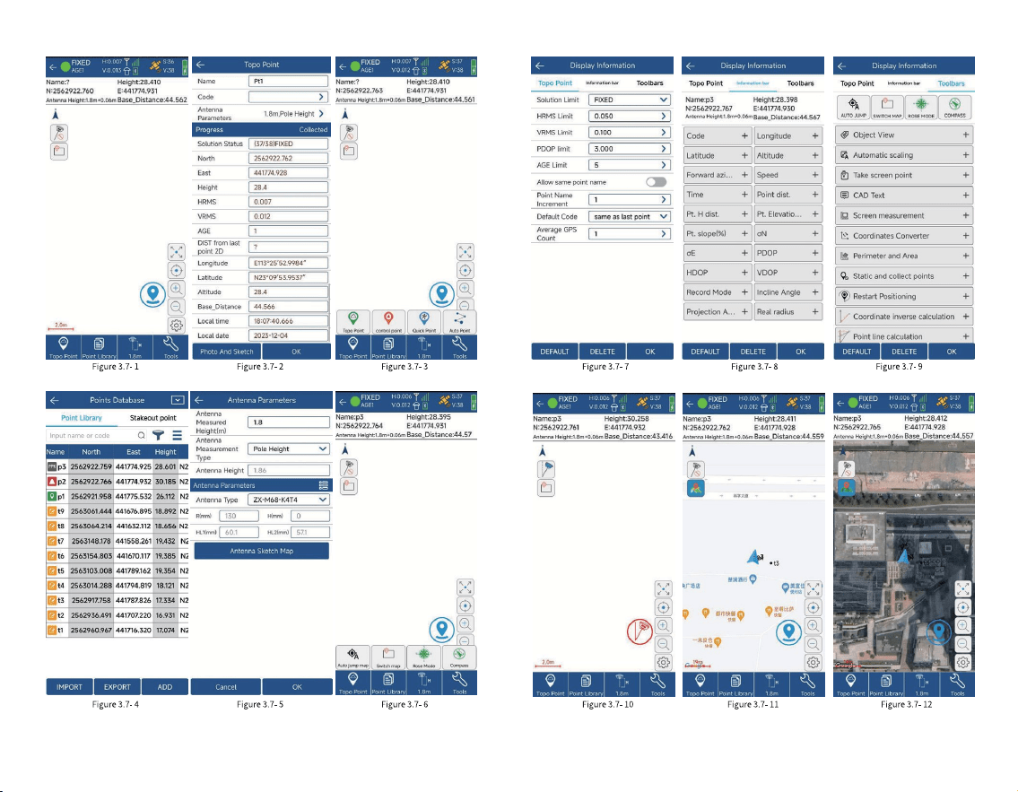
3. 7 Point Survey
Click [Survey] [Point Survey], as shown in Figure
3.7-1. The positioning output by the GNSS device is
measured and collected according to certain accuracy
constraints and stored in the coordinate point library. In the
point survey interface, the top title bar displays the basic
information of the positioning output by the current GNSS
device, the current solution status, differential delay, HRMS,
VRMS and other positioning accuracy assessment values,
and the number of received satellites. Below the title bar is
the status bar that displays other important information. The
display content can be congured according to the user's
demand. In point survey, the north-east high coordinates
and base station distance information are displayed by
default. The middle area is the measurement data drawing
information, and the network map can also be set to display.
The icon in the upper left corner of the drawing area
indicates the direction of the map, which is convenient for
users to determine the direction when needed. The lower
left corner of the drawing area shows the scale of the
drawing. Click the icon or on the right to enlarge or
reduce the scale of the drawing. Below the drawing area is
the display of function collection. These function menus can
also be displayed here according to the needs of the user in
the settings to quickly operate certain functions.
The icon in the lower right corner of the drawing
area is the button to trigger the survey collection function.
This button can be moved according to the user's usage
habits and placed in a more convenient place for operation.
Click the button to start the survey function, as shown in
Figure 3.7-2. You can enter the point name and code. Click
39 40

the icon to select the preset code in the code library to
quickly ll in the attributes of the feature. If there are many
codes in the code library, the codes with higher frequency of
use will be displayed in the front to facilitate users to quickly
select.
Below the drawing area are the measurement type
selection, coordinate point library entry, antenna height
setting, and tool menu.
Click [Topo Point], as shown in Figure 3.7-3. Four types
of point will pop up: Topo Point, Control Point, Quick Point,
and Auto Point. You can select the corresponding point type
for surveying according to actual needs.
Click [Point Library] to enter the coordinate point
library interface, as shown in Figure 3.7-4, where you can
view the surveying point status.
Click the icon to modify and edit the antenna height
information, as shown in Figure 3.7-5. The antenna height
setting is to subtract the antenna height from the phase
center coordinates of the GNSS to get the actual position of
the measured target on the ground. If the antenna
information is incorrect, click the antenna information to
select the correct antenna type in the antenna management
(used when the GNSS device does not output antenna
information or uses an external antenna).
Click [ Tools], as shown in Figure 3.7-6, you can quickly
operate certain functions in the menu as needed, or you can
add and delete functions in the toolbar according to user
needs in the settings.
Click the icon to enter the surveying setting
interface, as shown in Figure 3.7-7. Set the measurement
collection restriction conditions here, such as the solution
limit, HRMS Limit, VRMS Limit, PDOP Limit, AGE Limit, etc.
Users set the LIMIT conditions according to the accuracy
requirements of the operation. Setting the number of
smoothing points is to collect multiple positioning points
and calculate the average value to indicate the accuracy. In
addition, you can also set the default point name and default
code, etc. The information bar is to set the display content of
the status information bar. Users can set the display
according to the information they focus on, as shown in
Figure 3.7-8. The toolbar is for users to set common
functions according to their needs during the operation, so
that users can quickly and conveniently call certain
functions, as shown in Figure 3.7-9. These functions include:
Auto JUMP, Switch Map, ROSE mode, Take screen point,
CAD text, coordinates converter, Perimeter and area, CAD
background color, etc. Click the menu icon on the toolbar to
trigger the corresponding function.
Click the icon to automatically center the current
position on the screen. Click the icon to display all
current measurement points on the screen.
Click the icon , as shown in Figure 3.7-10, to turn
on/off the tilt measurement function.
Click the icon, as shown in Figure 3.7-11 and Figure
3.7-12, to select the network map you want to display.
41 42
43 44
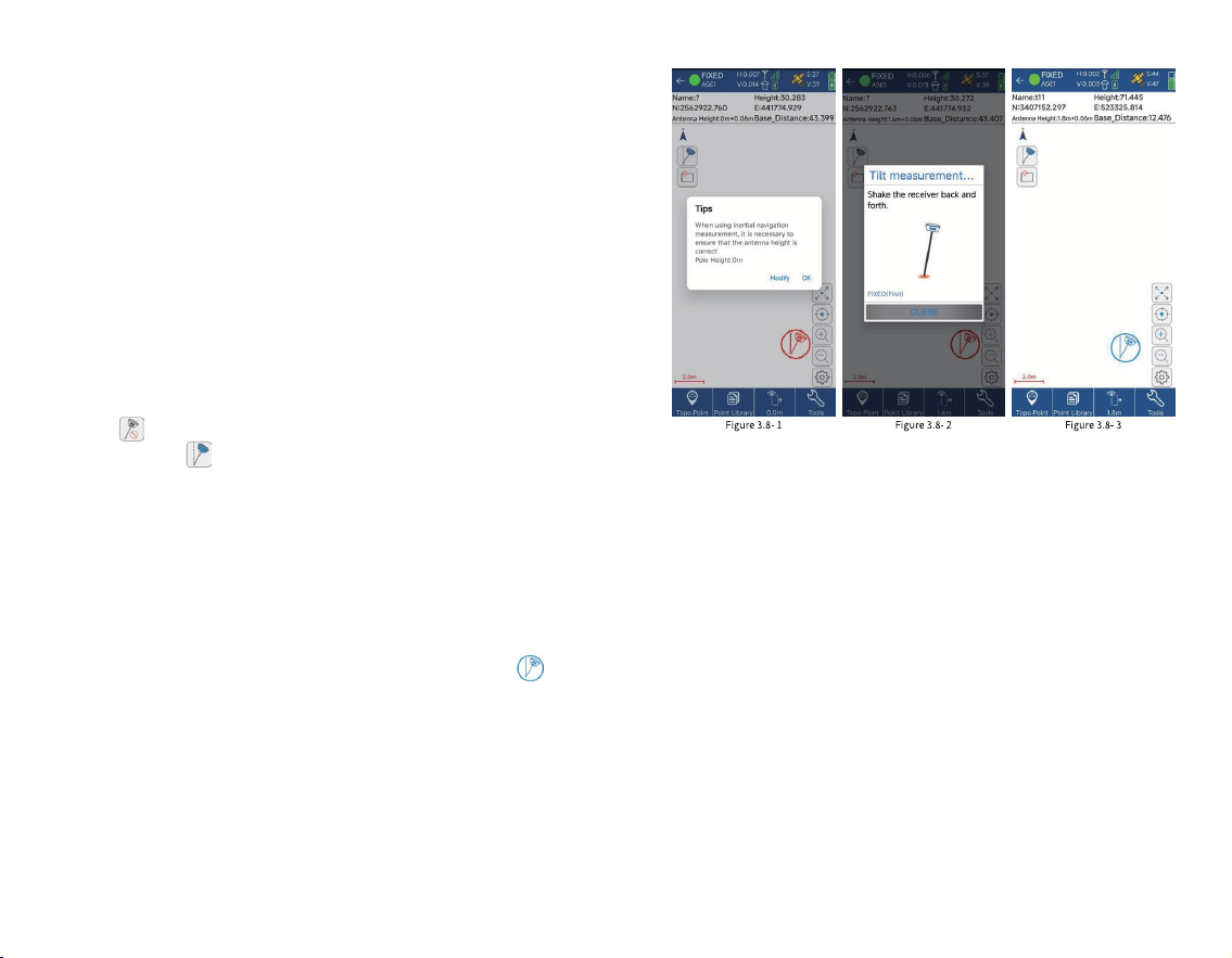
3.8 Tilt Survey
The tilt survey function requires the instrument to have
a tilt module. Instruments with this function can do the
following:
1. The accuracy of the instrument can be maintained
within 2cm within the tilt range of 60 °;
2. The calibration process is simple, just shake the
centering pole back and forth in place;
3. Support centering pole calibration, which can
eliminate the survey error caused by the curvature of the
centering pole.
Click [Survey] [Point Survey] to enter the point
Survey page, click the tilt survey icon in the upper left
corner to turn on the tilt survey function. When turned
on, the icon is....... Then follow the pop-up prompts, as
shown in Figure 3.8-1, and enter the antenna height
parameters (centering pole height) according to the actual
situation.
At this time, the instrument needs to be in a xed state.
Refer to the pop-up animation, as shown in Figure 3.8-2 ,
shake the centering pole back and forth for 5 to 10 seconds,
then rotate 90°, and continue to shake the centering rod
back and forth until the measurement icon changes to ......,
as shown in Figure 3.8-3 , and then you can perform tilt
survey.
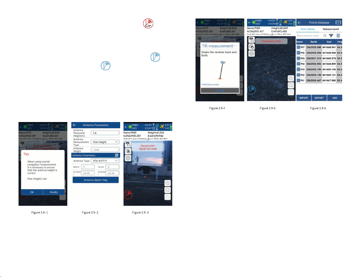
3.9 Laser Survey
Laser Survey requires connecting to an instrument with
laser measurement. It is a more convenient way of point
survey. It can measure wherever the laser can illuminate, and
can overcome obstacles, saving time and effort. When
connecting to an instrument with laser function, a laser
measurement icon will appear on the measurement
interface. When the laser measurement interface is turned
on, the instrument will emit a green laser. The coordinates of
the place where the laser illuminates can be measured.
Connect the receiver via WiFi, when you are using laser
measurement, the real-time laser position will be shown on
the screen.Click [Survey] [Laser Survey] to enter the laser
measurement interface, as shown in Figure 3.9-1. Follow the
pop-up prompts and enter the antenna height parameters
(centering pole height) according to the actual situation, as
shown in Figure 3.9-2. At this time, the instrument needs to
45 46
3.10 Point Stakeout
Click [Survey] [Point Stakeout] to enter the point
stakeout library interface, as shown in Figure 3.10-1. Point
stakeout means nding the location of a point through
coordinate points in the eld when the coordinates of the
point are known. Points that have not been staked out and
those have been staked out will be displayed. Click the
stakeout point to edit, view details, stake out, and delete the
stakeout point, as shown in Figure 3.10-2. The points to be
staked out are part of the coordinate point library. The
operations of adding, removing, importing, and exporting
stakeout points are the same as those in the coordinate
point library. Removing points from the points to be staked
out does not actually delete points in the point library. You
can also select points from the coordinate points (all points
in the coordinate point library) for stakeout. After selecting
points for stakeout, enter the point stakeout interface, as
shown in Figure 3.10-3.
47 48
be in a xed state, as shown in Figure 3.9-3. Click the
icon and refer to the pop-up animation, as shown in Figure
3.9-4, shake the centering pole back and forth for 5~10s,
then rotate 90, and continue to shake the centering pole
back and forth until the measurement icon changes to .......,
as shown in Figure 3.9-5. Click the icon to complete the
laser measurement data collection. In this interface, write the
laser measurement point name and code, and you can see
the laser measurement distance and measurement
accuracy.
Click [Point Library] to view laser measurement points
and common measurement points, as shown in Figure 3.9-6.
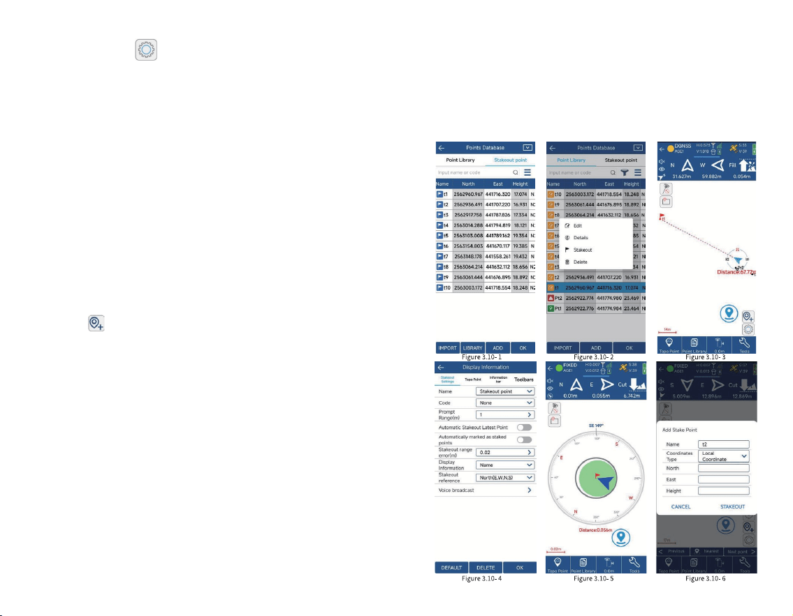
Click the icon to enter the layout setting interface,
as shown in Figure 3.10-4, where you can set the prompt
range, layout tolerance, etc. You can also set the reference
direction to east, south, west, north, front, back, left, right,
and voice broadcast.
The layout of the point stakeout interface is similar to
that of point survey, but there are some differences. The ll
and cut values of the southeast, northwest, and northeast
deviation values from the target are displayed in the status
information bar. The compass, the current positioning, the
measurement type, coordinate point library, antenna height
and tools, functions such as stake out the nearest point,
stake out the previous point, and stake out the next point are
displayed at the bottom of the drawing area.
Click [ Nearest Point], as shown in Figure 3.10-5, to
stake out the nearest point.
Click the icon, as shown in Figure 3.10-6, to manually
add stakeout points at any time.
How could we reach the destination faster?
If the user has a good sense of direction, he can
distinguish between east, south, west and north in real-time
eld work. In the layout compass display, he can directly see
the continuity between the current positioning point and the
target point, and just walk to the direction it points to. As
shown in Figure 3.10-3, you can nd the target point Pt 1 by
walking southwest.
What if the user has a poor sense of direction and
cannot distinguish between east, south, west and north?
You can look at the small arrow of the current location. The
direction of this small arrow is the direction of the tablet
when it is placed at. As shown in Figure 3.10-3, the current
tablet is pointing to the south. You can turn the tablet to
point to the same direction. When the tablet's direction
coincides with the current point and the target point, it
means that the tablet's direction is consistent with the
target point. At this time, follow the tablet's direction and
move forward.
49 50
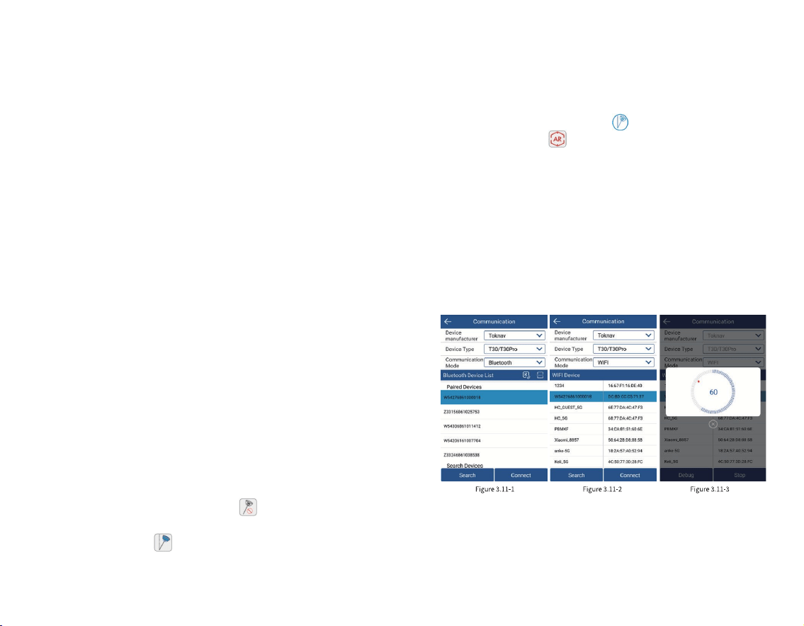
3.11 AR Stakeout
AR stakeout needs to be connected to an instrument
with AR function via WIFI to be displayed. It can provide
high-denition real-scene stakeout function and better
real-scene stakeout application to help you stake out the
target in one shot.
1.Click [Device] [Communication] to enter the
communication settings interface, as shown in Figure 3.11- 1.
Select the device type (RTK), communication mode (WIFI),
and then click [ Search], as shown in Figure 3.11- 2, view the
WIFI device list, select the corresponding device serial
number (default device number), and click [Connect] to
complete the device connection, as shown in Figure 3.11- 3.
After the device is successfully connected, it will directly
return to the device interface.
2.Congure the rover to achieve a xed solution state,
refer to Section 3.2.
Note: To use the Phone Internet, the controller needs to
have a SIM card inserted to connect to the Internet.
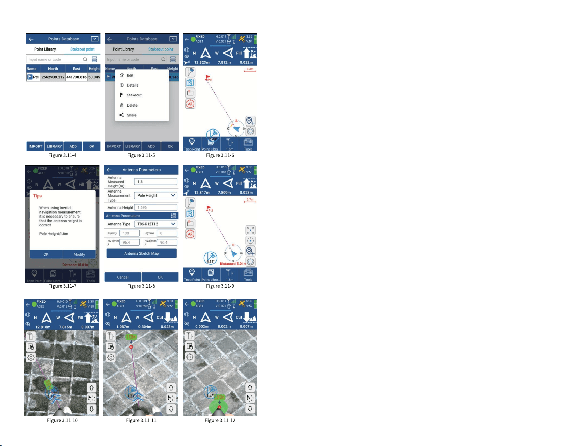
Click [Survey] [Point Stakeout] to enter the point
stakeout library interface, as shown in Figure 3.11-4. The
points to be staked will display the unstaken points and the
staked points. Click the staked point to edit, view the details,
stake out and delete the staked point, as shown in Figure
3.11-5. After selecting the point to stake out, enter the point
stakeout interface, as shown in Figure 3.11-6. Click the tilt
survey icon in the upper left corner to turn on the tilt
measurement function, as shown in Figure 3.11-7. When it is
turned on, the icon is .
Then follow the pop-up prompts and enter the antenna
height parameters (centering rod height) according to the
actual situation , as shown in Figure 3.11- 8. At this time, the
device needs to be in a xed state, shake the centering rod
back and forth for 5~10s, then rotate 90°, and continue to
shake the centering rod back and forth until the
measurement icon changes to , as shown in Figure 3.11-
9. Click the AR icon in the upper left corner, as shown in
Figure 3.11- 10, to enter AR real-scene stakeout.
Finally, follow the arrow direction and distance
indication to navigate to the area close to the stakeout point,
as shown in Figure 3.11-11. When the tip of the centering rod
coincides with the marked point, as shown in Figure 3.11-12,
the AR real-scene stakeout is completed. At this time, you
can click the measurement icon and choose to stake out the
next point, previous point, or stake out again according to
the pop-up prompt.
51 52
(Communication mode
needs to select WIFI)
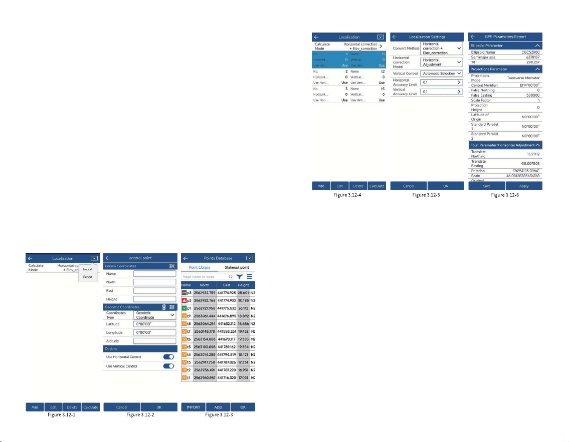
3.12 Localization
Click [Project][Localization], as shown in Figure
3.12-1, you can import control point parameters in various
formats, or export control point data into les by third-party
software. The high-precision position obtained by the
software from the GNSS device is the latitude and longitude
coordinates of satellite positioning, but in actual project
operations, the plane coordinates on the ground are
ultimately required for survey and application. If the
customer has coordinates conversion parameters, the
coordinate system parameter values can be set directly in
the coordinate system (details 2.3). If the customer does not
have specic coordinate system parameters, but has
corresponding latitude and longitude coordinates and plane
coordinates, we call them control points. In the case of
control point data, this function can be used to calculate the
conversion parameters and apply them to project
operations.
Click [Add], as shown in Figure 3.12-2, you can manually
enter the control point, or choose to import it from the
coordinate point library, as shown in Figure 3.12-3. In the
control point list, select the data item to modify, edit and
delete the control point parameters, as shown in Figure
3.12-4.
After editing the control point parameters, calculate the
conversion parameters for the control points. Click
[Calculate Method] to pop up the conversion parameter
condition settings, as shown in Figure 3.12-5. Coordinate
conversion methods include plane correction, vertical
correction, elevation tting and seven parameters, which
can be all or part of the combination. As long as the
53 54
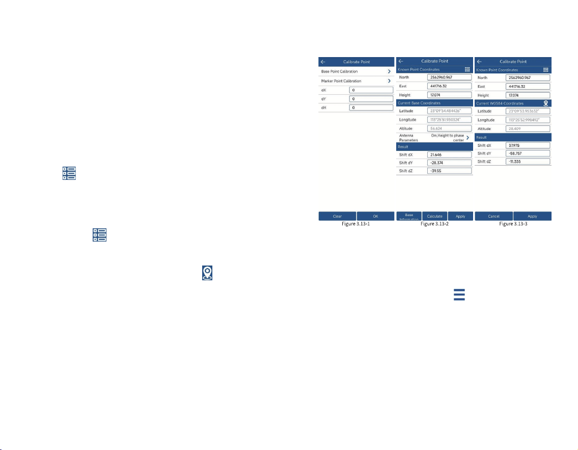
3.13 Calibrate Point
Click [Project] [Calibrate Point], as shown in Figure
3.13-1. In actual application, GNSS equipment obtains
high-precision position by combining differential data of
base station with solution. Here we know the coordinate
position of base station. In fact, the high-precision position
output by GNSS equipment is the relative position of base
station. In actual application, some users using differential
data of CORS reference station, there are also quite a few
users using differential data of base station transmitted by
their own GNSS equipment. When transmitting differential
data by building their own stations, a project may involve
starting base station multiple times. When initiating the
base station, the starting position and starting coordinates
of base station may change, and the starting coordinates
may not be correct. In the absence of calibration, the
coordinates of rover obtained by using these base station
corresponding accuracy is achieved within the accuracy
range, the calculated conversion parameters are considered
to be available. The plane correction model includes four
parameters and horizontal adjustment. The elevation tting
method includes weighted average, plane tting, surface
tting and vertical adjustment. Usually, if the operating
range is very wide, seven parameters are needed to meet
the accuracy requirements of all control points. If the
operating range is relatively small, plane correction can
usually achieve the corresponding accuracy.
After conguring the calculation conditions, click
[Calculate] to display the calculation results of the
conversion parameters and the residuals of each control
point, as shown in Figure 3.12-6. After calculating the
conversion parameters, you can export the calculation
report for project review. If the conversion parameters are
qualied, apply the parameters to the project and you can
perform the surveying work normally.
3.10 Point Stakeout
Click [Survey] [Point Stakeout] to enter the point
stakeout library interface, as shown in Figure 3.10-1. Point
stakeout means nding the location of a point through
coordinate points in the eld when the coordinates of the
point are known. Points that have not been staked out and
those have been staked out will be displayed. Click the
stakeout point to edit, view details, stake out, and delete the
stakeout point, as shown in Figure 3.10-2. The points to be
staked out are part of the coordinate point library. The
operations of adding, removing, importing, and exporting
stakeout points are the same as those in the coordinate
point library. Removing points from the points to be staked
out does not actually delete points in the point library. You
can also select points from the coordinate points (all points
in the coordinate point library) for stakeout. After selecting
points for stakeout, enter the point stakeout interface, as
shown in Figure 3.10-3.
55 56
3.14 Coordinate Point library
Click [Project] [ Points Database], as shown in Figure
3.14- 1. Here you can view and manage the point data in the
project, including adding, editing, deleting, and importing.
Click the upper right corner , as shown in Figure
3.14-2, to switch the display style of point information.
Click [Add], as shown in Figure 3.14-3, and you can
manually enter the point name, code and corresponding
coordinates;
Click [Import], as shown in Figure 3.14- 4, select the le
format of the point data to be imported, and then select the
data le to complete the data import.
Select the coordinate point and click [Edit], as shown in
Figure 3.14-5, you can edit and modify the name and code of
the coordinate point;
differentials may be wrong (at the same location, the
coordinates measured by previous differential data are
different from the coordinates obtained by new differential
data). Therefore, when the rover receives new base station
differential data for surveying, it needs to perform points
calibration so that the coordinates obtained by software
match the coordinates obtained by connecting to the last
base station. After the starting coordinates or starting
position of the base station changes, a known position needs
to be used to calibrate the coordinates correctly.
Click [Base Point Calibration], as shown in Figure 3.13-2,
and click to select a known point in the coordinate point
library (use the coordinates measured by the base station at
a certain location last time). Then click [Calculate] and
apply.
Click [ Marker Point Calibration], as shown in Figure
3.13-3, and click select a known point in the coordinate
point library (use the coordinates measured by the base
station at a certain location last time), then place the GNSS
device at the location of the known point. Click to measure
a new positioning point, and calculate the deviation value.
Click [Apply], and the coordinates received by the software
will match the coordinates measured last time.
The base station coordinates change and remind you
whether to recalibrate. If the base station coordinates
change when receiving the differential signal from the
self-built base station, it means that the points calibration of
base station is required and needs to be re-calibrated.
Note: The CORS reference station is a long-term
operating reference station whose position and startup
coordinates will not change. If the differential data of the
CORS reference station is used, the received coordinates
may change, the obtained coordinates are still correct and
no translation calibration is required.
Click the icon to enter the layout setting interface,
as shown in Figure 3.10-4, where you can set the prompt
range, layout tolerance, etc. You can also set the reference
direction to east, south, west, north, front, back, left, right,
and voice broadcast.
The layout of the point stakeout interface is similar to
that of point survey, but there are some differences. The ll
and cut values of the southeast, northwest, and northeast
deviation values from the target are displayed in the status
information bar. The compass, the current positioning, the
measurement type, coordinate point library, antenna height
and tools, functions such as stake out the nearest point,
stake out the previous point, and stake out the next point are
displayed at the bottom of the drawing area.
Click [ Nearest Point], as shown in Figure 3.10-5, to
stake out the nearest point.
Click the icon, as shown in Figure 3.10-6, to manually
add stakeout points at any time.
How could we reach the destination faster?
If the user has a good sense of direction, he can
distinguish between east, south, west and north in real-time
eld work. In the layout compass display, he can directly see
the continuity between the current positioning point and the
target point, and just walk to the direction it points to. As
shown in Figure 3.10-3, you can nd the target point Pt 1 by
walking southwest.
What if the user has a poor sense of direction and
cannot distinguish between east, south, west and north?
You can look at the small arrow of the current location. The
direction of this small arrow is the direction of the tablet
when it is placed at. As shown in Figure 3.10-3, the current
57 58
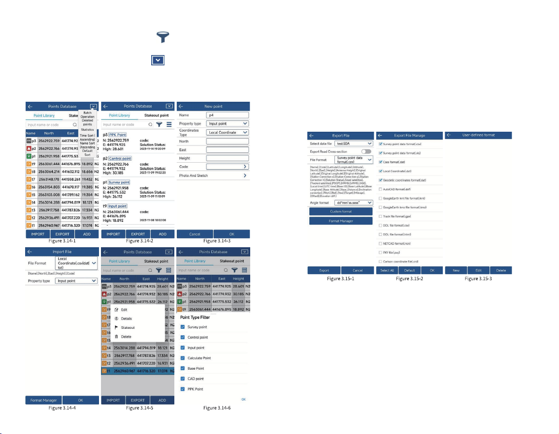
3.15 Export File
Click [Project] [ Export File], as shown in Figure
3.15-1, and select the type, le format, and angle format of
the exported data as needed. Click [ Format Manager], as
shown in Figure 3.15-2, select the le format of the data to
be exported, and click [OK]. Click [User-dened Format], as
shown in Figure 3.15-3, and you can manually create and edit
the le format of the exported data.
Click the upper right corner , as shown in Figure
3.14-6, to lter the point type.
Click the upper right corner and the operation will
pop up, as shown in Figure 3.14-1. You can perform batch
deletion, data statistics, sorting and other functions as
needed;
59 60
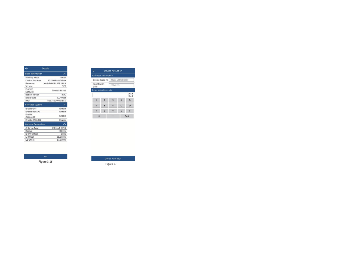
3.16 Device Information
Click [Device] [Device Information], as shown in
Figure 3.16, to view basic information such as the GNSS
device's working mode, device serial number, Firmware
Version, Battery Power, expiry date, Satellites System,
Antenna Parameters, etc.
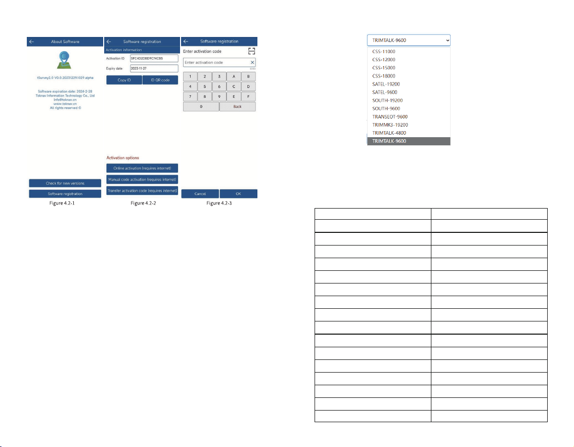
4.2 Software Registration
Click [Project] [About Software], as shown in Figure
4.2-1, to view the software version information and
registration authorization information.
Click [Check for new versions], if there is a new version,
the new version update information will pop up, click
[Update] to update the software to the latest version. If
there is no new version, it will prompt that it is already the
latest version.
Click [Software Registration] to jump to the software
registration interface, as shown in Figure 4.2-2, to view the
activation ID and expiry date.
When you install the software for the rst time, click
[Online Activation] to activate it for three months of free
trial.
Click [Manual Code Activation], as shown in Figure
4.2-3, enter the authorization code here or scan the QR code
of the authorization code to activate the software.
If you need to replace a new controller, you can click
[Transfer activation code] in the old controller, then enter
the software registration of the new controller and enter the
transferred activation code to activate the software.
61 62
4. Device Activation and Software
Registration
4.1 Device Activation
Click [Device] [Device Activation], as shown in Figure
4.1, to view the device serial number and expiry date. If the
GNSS device has expired, you can obtain the registration
code from the dealer and authorize the device here.
5.2 Default Channel Frequency
The device has 16 default channel frequencies, and the
frequency of each channel supports custom conguration
modication.
63 64
5. Built-in Radio
T50 is equipped with a 1.5Watt digital radio that
supports integrated transmission and reception. Users can
choose three power levels: low (0.5W), and high (1.5W).
Note: Every time you set the data link to the built-in
radio, you need to install the radio antenna in advance.
Please open the UHF radio cover on the bottom of the
housing and then install it.
5.1 Radio Protocol
The device currently supports the following 10 radio
protocols, which you can adjust it according to your needs.
aisle
1
2
3
4
5
6
7
8
9
10
11
12
13
14
15
16
463.125
464.125
465.125
466.125
463.625
464.625
465.625
466.625
463.375
464.375
465.375
466.375
463.875
464.875
465.875
466.875
Frequency/MHz
65 66
6. Technical Indicators
SYSTEM
GNSS
HARDWARE SYSTEM ARM Cortex-A7 1.8GHz
Linux
Horizontal: 1.5m / Vertical: 2.5m
Horizontal: 0.4m / Vertical: 0.8m
20ns
Horizontal: ± (8mm+1ppm)
Vertical: ± (15mm+1ppm)
Horizontal: ± (2.5mm+1ppm)
Vertical: ± (5mm+1ppm)
0.03m/s
<2cm
Horizontal: ± (8mm+1ppm)
Vertical: ± (15mm+1ppm)
≤2.5cm 3D error within
5m range
OS
GPS
GLONASS
BDS
GALILEO
QZSS
SBAS
NavIC (IRNSS)
Channel
Standard Output
Correction I/O Protocol
Frequency
Reacquisition Time
Cold Start Time
T50
Type-C power adapter
Type-C To Type-C
Radio Antenna
1 Unit
2 PCS
1 PCS
1 PCS
SINGLE (RMS)
BR+EDR+BLEBluetooth
802.11 b/g/n
LTE FDD: B1/2/3/4/5/7/8/12/13/
18/19/20/25/26/28
LTE TDD: B38/39/40/41
WCDMA: B1/2/4/5/6/8/19
GSM: B2/3/5/8
WIFI
Network
Protocols: TRIMTALK, TRIMMK3,
SOUTH, TRANSEOT, SATEL, LORA
Air Baud Rate: 4800, 9600, 19200
Radio
Type: Class 3R
Range: 30m
Precision: ±5mm±100*10-6*D,
(D: Measurement Distance)
Wavelength: 520±20nm
Power: 3.8mW
7.4V, 6500mAh
-30°C~+65°C
Over 16 hours(when applying
controller network mode)
USB PD 15V/2A 5V/3A
Can withstand a 1.5m drop at
normal temperatures
Capacity
Endurance
Operating Temperature
-40°C~+85°C
IP68
Storage Temperature
Shock Resistance
Protection Rating
Φ132 * 83mm
Dimensions
770g
Weight
Magnesium alloy casing with
ABS/PC plastic top cover
Materials
Charging
Laser Module
AR Stakeout Supported
Sensor: 1/2.8 inch
Aperture: f/2.5
Resolution: 1920*1080
FOV: 69.3°±3°
Distortion: <0.38%
AR Camera
Sensor:1/3.06 inch
Resolution: 4224x3200
FOV: D44°H35°V26.5°
Distortion: <1%
Laser Assist Camera
Storage 32GB storage
Integrated high-power transceiver
Frequency Range: 410~470MHz
Power: 0.5W/1.5W
DGPS (RMS)
RTK (RMS)
Time Accuracy(RMS)
Static(RMS)
Tilt Compensation
(≤60°)
AR Stake Out Accuracy
Laser Measurement
Speed Accuracy(RMS)
L1C/A, L1C, L2P(Y), L2C, L5
L1, L2, L3
B1I, B2I, B3I, B1C, B2a, B2b(PPP)
E1, E5a, E5b, E6(PPP)
L1, L2, L5
L1(PPP)
L5*(Requires rmware support)
1408
NMEA-0183
RTCM 3.X
20Hz max
<1s
<40s
ACCURACY
BATTERY / CHARGE
ENVIRONMENT
PHYSICAL
ACCESSORIES
SYSTEM PLATFORM
Europe, North & South America
Tel & WhatsApp: +1 (323) 847-7713 (Ian)
Asia, Africa & Oceania
Tel & WhatsApp: +86 139 2607 5986 (Jeffrey)
Guangzhou Toksurvey Information Technology Co., Ltd
Manufacturers may update parameters at any time, please
refer to the latest product information.
No. 9 Caipin Road, Building B, Room 801-6,
Huangpu District, Guangzhou, China
.toknav.cn info@toknav.cn

Frequency Bands:
GSM 900: 880 MHz to 915 MHz
GSM1800: 1710 MHz to 1785 MHz
WCDMA Band I: 1920 MHz to 1980 MHz
WCDMA Band VIII: 880 MHz to 915 MHz
LTE Band 1: 1920 MHz to 1980 MHz
LTE Band 3: 1710 MHz to 1785 MHz
LTE Band 7: 2500 MHz to 2570 MHz
LTE Band 8: 880 MHz to 915 MHz
LTE Band 20: 832 MHz to 862 MHz
LTE Band 28: 703 MHz to 736 MHz
LTE Band 38: 2570 MHz to 2620 MHz
LTE Band 40: 2300 MHz to 2400 MHz
WLAN 802.11b/g/n20: 2412 MHz to 2472MHz
WLAN 802.11n40: 2422 MHz to 2462MHz
WLAN 802.11a/n20/n40/ac20/ac40/ac80: 5150 MHz to 5250 MHz
WLAN 802.11a/n20/n40/ac20/ac40/ac80: 5725 MHz to 5850 MHz
Bluetooth: 2402 MHz to 2480 MHz
GPS: 1575.42 MHz ± 1.023 MHz
BDS: 1561.098MHz
GLONASS: 1602 MHz
GALILEO: 1575.42 MHz
NFC: 13.56MHz
Max power:
GSM 900: 30.33dBm
GSM1800: 25.89dBm
WCDMA Band I: 23.73dBm
WCDMA Band VIII: 24.14dBm
LTE Band 1: 24.25dBm
LTE Band 3: 24.05dBm
LTE Band 7: 23.21dBm
LTE Band 8: 24.33dBm
LTE Band 20: 24.19dBm
LTE Band 28: 24.23dBm
LTE Band 38: 23.80dBm
LTE Band 40: 23.03dBm
2.4GHz WLAN: 17.88dBm
5GHz WLAN: 16.37dBm
5.8GHz WLAN: 13.61dBm
Bluetooth: 6.66dBm
BLE: -1.73dBm
Modulation Mode:
GSM: GMSK for GPRS; GMSK and 8PSK for EDGE
WCDMA: QPSK; HSDPA: QPSK/16QAM; HSUPA: BPSK
LTE: QPSK/16QAM
2.4G WLAN: 802.11b(DSSS): CCK, DQPSK, DBPSK
802.11g(OFDM): BPSK, QPSK,16-QAM,64-QAM
802.11n(OFDM): BPSK, QPSK,16-QAM,64-QAM
5G WLAN: 802.11a/n(OFDM): BPSK, QPSK,16-QAM,64-QAM
802.11ac (OFDM): BPSK, QPSK,16-QAM,64-QAM,256-QAM
Bluetooth: BT(1Mbps): GFSK
BT EDR(2Mbps): π/4-DQPSK
BT EDR(3Mbps): 8DPSK
BLE: GFSK
GPS: BPSK
BDS: QPSK
GLONASS: FDMA
GALILEO: CBOC
NFC: ASK
BDR + EDR: Channel Spacing: 1MHz
BLE: Channel Spacing: 2MHz
2.4G WIFI Channel Spacing: 5MHz
5G WIFI Channel Spacing: 10MHz
WCDMA Channel Spacing: 200KHz
GSM Channel Spacing: 200KHz
GSM/WCDMA/LTE: PCB Antenna, Gain(s): GSM 900: -1.19dBi, GSM1800: 2.24dBi;
WCDMA: B1: -5.1dBi, B8: -1.19dBi;
LTE: B1: -5.1dBi, B3: 2.24dBi, B7: 2.24dBi, B8: -1.19dBi, B20: -4.83dBi, B28: -4.83dBi,
B38: -2.29dBi, B40: -1.48dBi
Bluetooth: PCB Antenna, Gain(s): 2.08dBi;
WLAN: PCB Antenna, Gain(s): 2.4GHz: 2.08dBi, 5GHz: 2.51dBi, 5.8GHz: 2.51dBi,
GNSS: PCB Antenna,
NFC: Coil Antenna, Gain(s): 0dBi.
CE Maintenance
1.Risk of explosion if battery is replaced by an incorrect type. Dispose of used batteries
according to the instructions.
2.The product shall only be connected to a USB interface of version Type-C.
3.Adapter shall be installed near the equipment and shall be easily accessible.
4.EUT Operating temperature range: -10° C to 45° C .
5.Adapter: The plug considered as disconnect device of adapter
Power supply and ADP(rating):
Input: AC 100-240V 50/60HZ 0.8A Max
Output: DC 3.3-11.0V 2.72A 29.92W or 5.0V 3.0A 15.0W or 9.0V 3.0A 27.0W or 12.0V 2.5A
30.0W or 15.0V 2.0A 30.0W
6.The device complies with RF specifications when the device used at 20cm you’re your body.
This product may be used in the following European member states subject to the following
restrictions. For products that operate in the frequency band 5.150 to 5.250 GHz, wireless
access systems (WAS), including radio local area networks (RLANs), shall be restricted to
indoor use.
Declaration of Conformity
Guangzhou Toksurvey Information Technology Co., Ltd hereby declares that this High
Precision GNSS Receiver is in compliance with the essential requirements and other
relevant provisions of Directive 2014/53/EU. In accordance with Article 10(2) and Article
10(10),This product is allowed to be used in all EU member states.

FCC Caution.
This device complies with part 15 of the FCC Rules. Operation is subject to the following two
conditions:
(1) This device may not cause harmful interference, and
(2) this device must accept any interference received, including interference that may cause
undesired operation.
Any Changes or modifications not expressly approved by the party responsible for compliance
could void the user's authority to operate the equipment.
Note: This equipment has been tested and found to comply with the limits for a Class B digital
device, pursuant to part 15 of the FCC Rules. These limits are designed to provide reasonable
protection against harmful interference in a residential installation. This equipment generates
uses and can radiate radio frequency energy and, if not installed and used in accordance with the
instructions, may cause harmful interference to radio communications. However, there is no
guarantee that interference will not occur in a particular installation. If this equipment does
cause harmful interference to radio or television reception, which can be determined by turning
the equipment off and on, the user is encouraged to try to correct the interference by one or
more of the following measures:
-Reorient or relocate the receiving antenna.
-Increase the separation between the equipment and receiver.
-Connect the equipment into an outlet on a circuit different from that to which the receiver is
connected.
-Consult the dealer or an experienced radio/TV technician for help.
FCC Radiation Exposure Statement:
This equipment complies with FCC radiation exposure limits set forth for an uncontrolled
environment. This equipment should be installed and operated with minimum distance 20 cm
between the radiator & your body.