www.sysinnotec.com
iAeris6 Indoor Air Quality Detector
U S E R M A N U A L
* Please read this manual carefully
before using this product.
Rev. 1.3 Jul. 2026
iAeris6 user manual
PACKAGE CONTENTS
PRODUCT DESIGN/FEATURES
Front/Right side/Embedded Installation
Back site
PRODUCT DIMENSIONS
WALL MOUNT INSTALLATION
APPLICABLE JUNCTION BOX TYPES
STAND MOUNT INSTALLATION
USER INTERFACE - HOME
Details page
Settings page
Contents
CONNECT TO ETHERNET
LOG IN TO THE SETTINGS WEBPAGE
WiFi Setup Process
CLOUD PLATFORM INTERFACE
(OPTIONAL)
Register Account
Cloud Platform Login Homepage
Historical Data Trend Curve
Customer Area Functionality
INSTALLATION POSITION
RECOMMENDATIONS
PRECAUTIONS
IAERIS6 UI FUNCTION DESCRIPTION
IAERIS6 LOGIN SETTINGS
Appendix
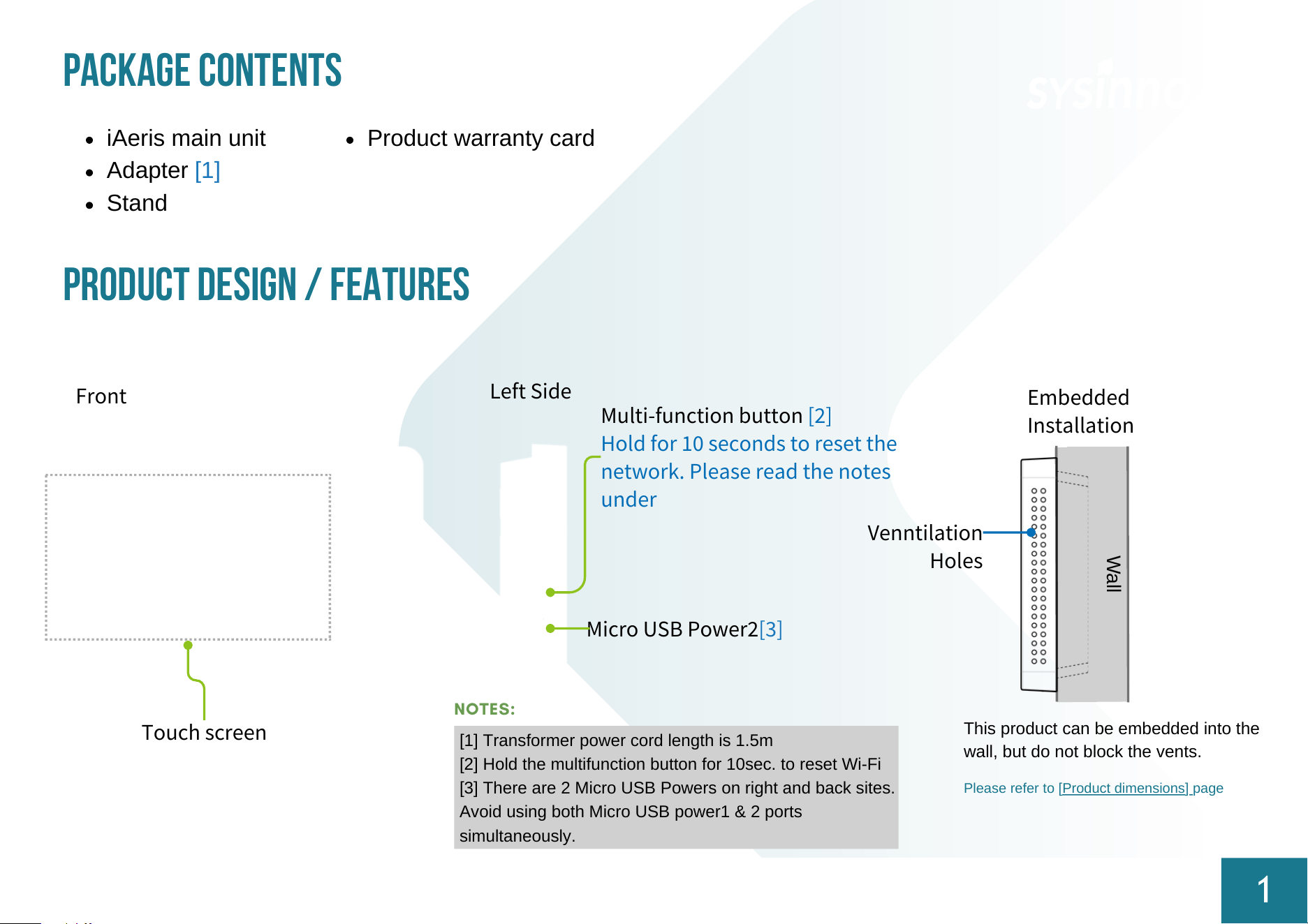
Micro USB Power2[3]
Venntilation
Holes
Wall
Multi-function button [2]
Hold for 10 seconds to reset the
network. Please read the notes
under
This product can be embedded into the
wall, but do not block the vents.
Please refer to [Product dimensions] page
PACKAGE CONTENTS
iAeris main unit
Adapter [1]
Stand
PRODUCT DESIGN / FEATURES
1
Front
Touch screen
Left Side
Embedded
Installation
Product warranty card
NOTES:
[1] Transformer power cord length is 1.5m
[2] Hold the multifunction button for 10sec. to reset Wi-Fi
[3] There are 2 Micro USB Powers on right and back sites.
Avoid using both Micro USB power1 & 2 ports
simultaneously.
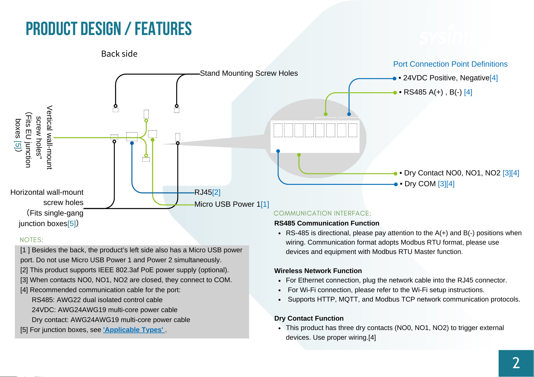
• RS485 A(+) , B(-) [4]
• Dry Contact NO0, NO1, NO2 [3][4]
Micro USB Power 1[1]
Port Connection Point Definitions
• 24VDC Positive, Negative[4]
Stand Mounting Screw Holes
Horizontal wall-mount
screw holes
(
Fits single-gang
junction boxes[5]
)
PRODUCT DESIGN / FEATURES
2
NOTES:
[1 ] Besides the back, the product’s left side also has a Micro USB power
port. Do not use Micro USB Power 1 and Power 2 simultaneously.
[2] This product supports IEEE 802.3af PoE power supply (optional).
[3] When contacts NO0, NO1, NO2 are closed, they connect to COM.
[4] Recommended communication cable for the port:
RS485: AWG22 dual isolated control cable
24VDC: AWG24AWG19 multi-core power cable
Dry contact: AWG24AWG19 multi-core power cable
[5] For junction boxes, see 'Applicable Types' .
COMMUNICATION INTERFACE:
RS485 Communication Function
RS-485 is directional, please pay attention to the A(+) and B(-) positions when
wiring. Communication format adopts Modbus RTU format, please use
devices and equipment with Modbus RTU Master function.
Wireless Network Function
For Ethernet connection, plug the network cable into the RJ45 connector.
For Wi-Fi connection, please refer to the Wi-Fi setup instructions.
Supports HTTP, MQTT, and Modbus TCP network communication protocols.
Dry Contact Function
This product has three dry contacts (NO0, NO1, NO2) to trigger external
devices. Use proper wiring.[4]
Back side
Vertical wall-mount
screw holes"
(
Fits EU junction
boxes [5]
)
• Dry COM [3][4]
RJ45[2]
3
PRODUCT DIMENSTIONS
Unit:mm
或
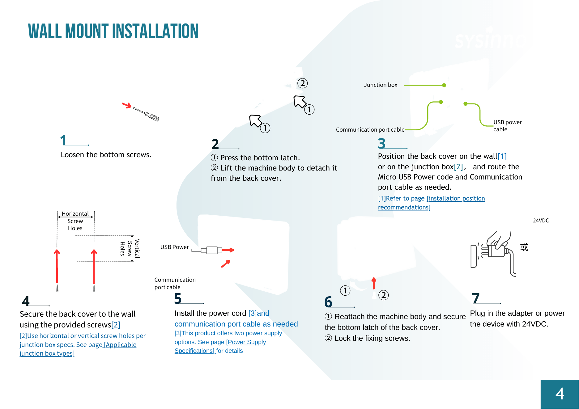
Plug in the adapter or power
the device with 24VDC.
Horizontal
Screw
Holes
Vertical
Screw
Holes
Communication port cable
USB power
cable
Junction box
②
①
①
Install the power cord [3]and
communication port cable as needed
[3]This product offers two power supply
options. See page
[Power Supply
Specifications] for details
USB Power
Communication
port cable
Secure the back cover to the wall
using the provided screws[2]
[2]Use horizontal or vertical screw holes per
junction box specs. See page
[Applicable
junction box types]
Loosen the bottom screws.
①
Press the bottom latch.
②
Lift the machine body to detach it
from the back cover.
24VDC
Position the back cover on the wall[1]
or on the junction box[2]
,
and route the
Micro USB Power code and Communication
port cable as needed.
[1]Refer to page [installation position
recommendations]
①
Reattach the machine body and secure
the bottom latch of the back cover.
②
Lock the fixing screws.
①
②
WALL MOUNT INSTALLATION
4
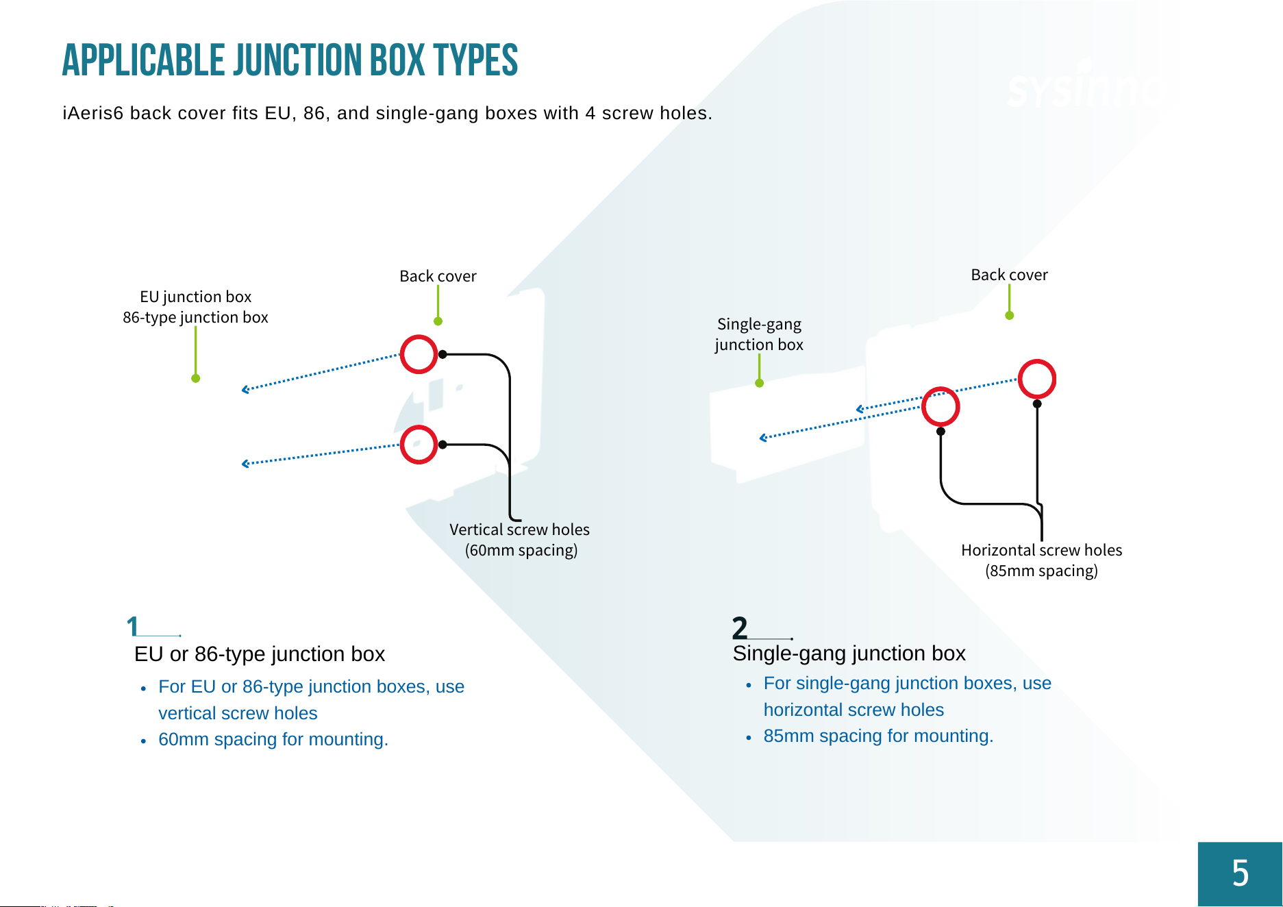
EU or 86-type junction box
iAeris6 back cover fits EU, 86, and single-gang boxes with 4 screw holes.
Applicable junction box types
5
Single-gang junction box
EU junction box
86-type junction box
Back cover
Vertical screw holes
(60mm spacing)
For EU or 86-type junction boxes, use
vertical screw holes
60mm spacing for mounting.
For single-gang junction boxes, use
horizontal screw holes
85mm spacing for mounting.
Single-gang
junction box
Horizontal screw holes
(85mm spacing)
Back cover
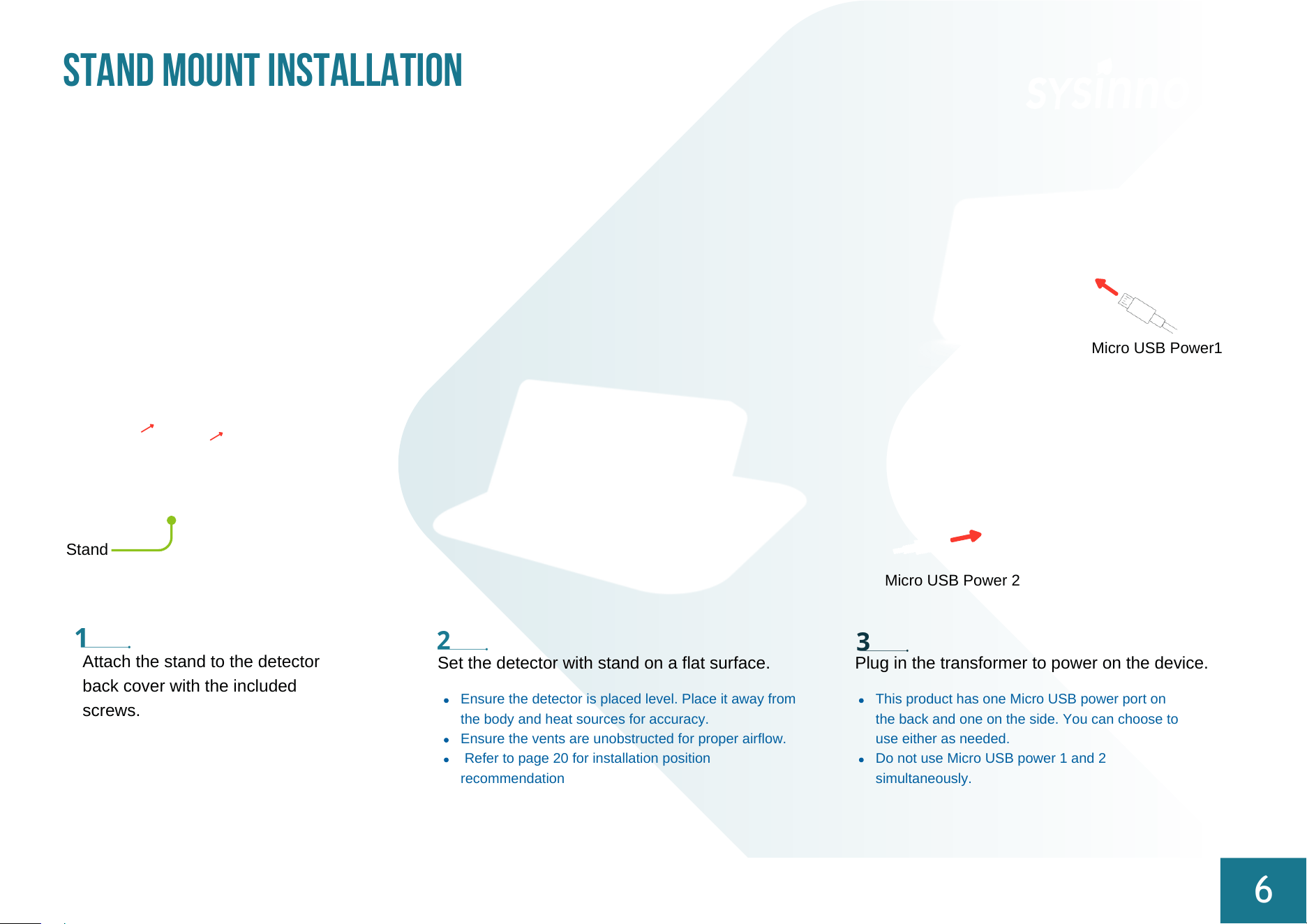
Attach the stand to the detector
back cover with the included
screws.
Micro USB Power1
Micro USB Power 2
Stand
Set the detector with stand on a flat surface.
Ensure the detector is placed level. Place it away from
the body and heat sources for accuracy.
Ensure the vents are unobstructed for proper airflow.
Refer to page 20 for installation position
recommendation
STAND MOUNT INSTALLATION
6
Plug in the transformer to power on the device.
This product has one Micro USB power port on
the back and one on the side. You can choose to
use either as needed.
Do not use Micro USB power 1 and 2
simultaneously.
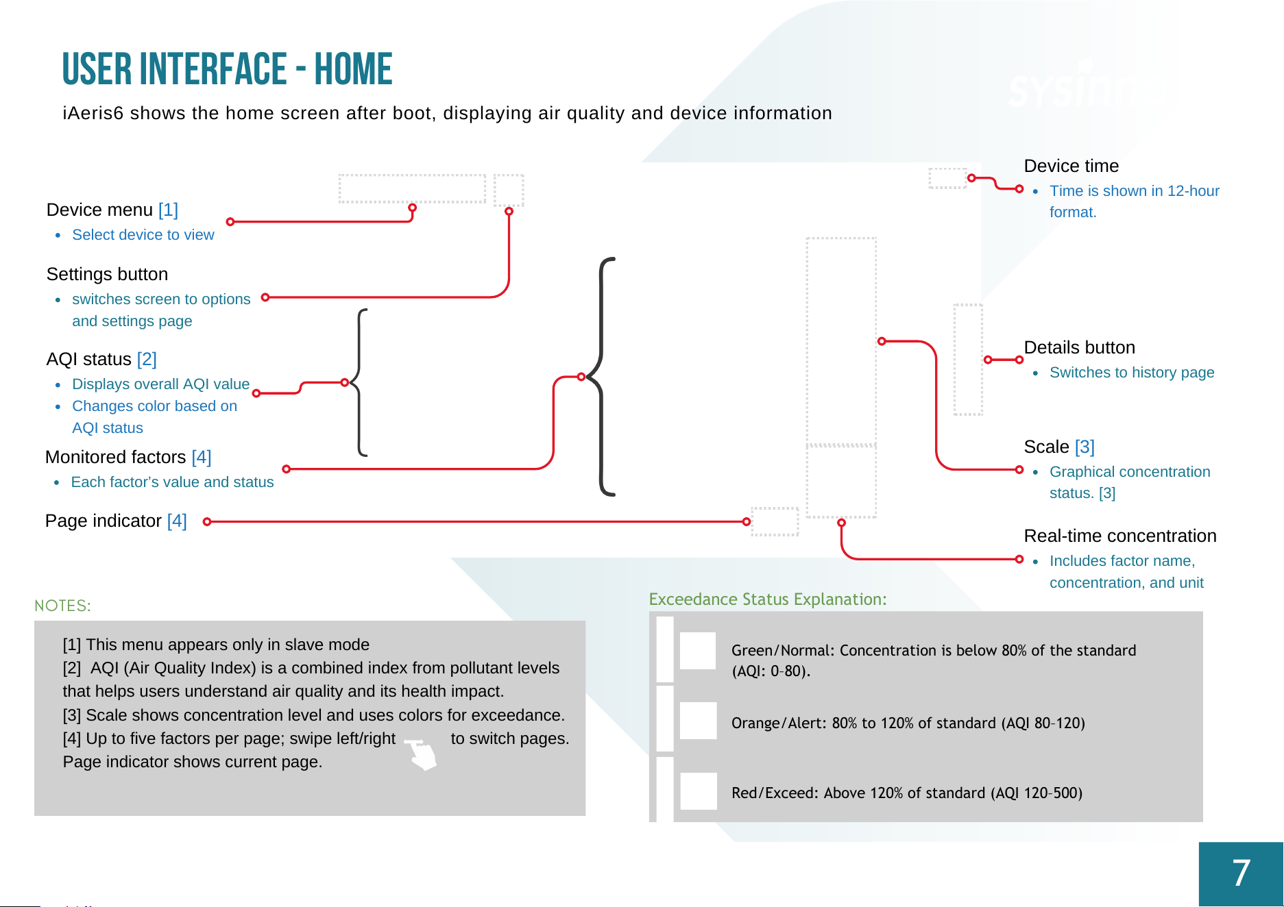
[1] This menu appears only in slave mode
[2] AQI (Air Quality Index) is a combined index from pollutant levels
that helps users understand air quality and its health impact.
[3] Scale shows concentration level and uses colors for exceedance.
[4] Up to five factors per page; swipe left/right to switch pages.
Page indicator shows current page.
Device menu [1]
Select device to view
USER INTERFACE - HOME
7
iAeris6 shows the home screen after boot, displaying air quality and device information
AQI status [2]
Displays overall AQI value
Changes color based on
AQI status
Monitored factors [4]
Each factor’s value and status
Settings button
switches screen to options
and settings page
Details button
Switches to history page
Device time
Time is shown in 12‑hour
format.
NOTES:
Real-time concentration
Includes factor name,
concentration, and unit
Scale [3]
Graphical concentration
status. [3]
Exceedance Status Explanation:
Red/Exceed: Above 120% of standard (AQI 120–500)
Orange/Alert: 80% to 120% of standard (AQI 80–120)
Green/Normal: Concentration is below 80% of the standard
(AQI: 0–80).
Page indicator [4]
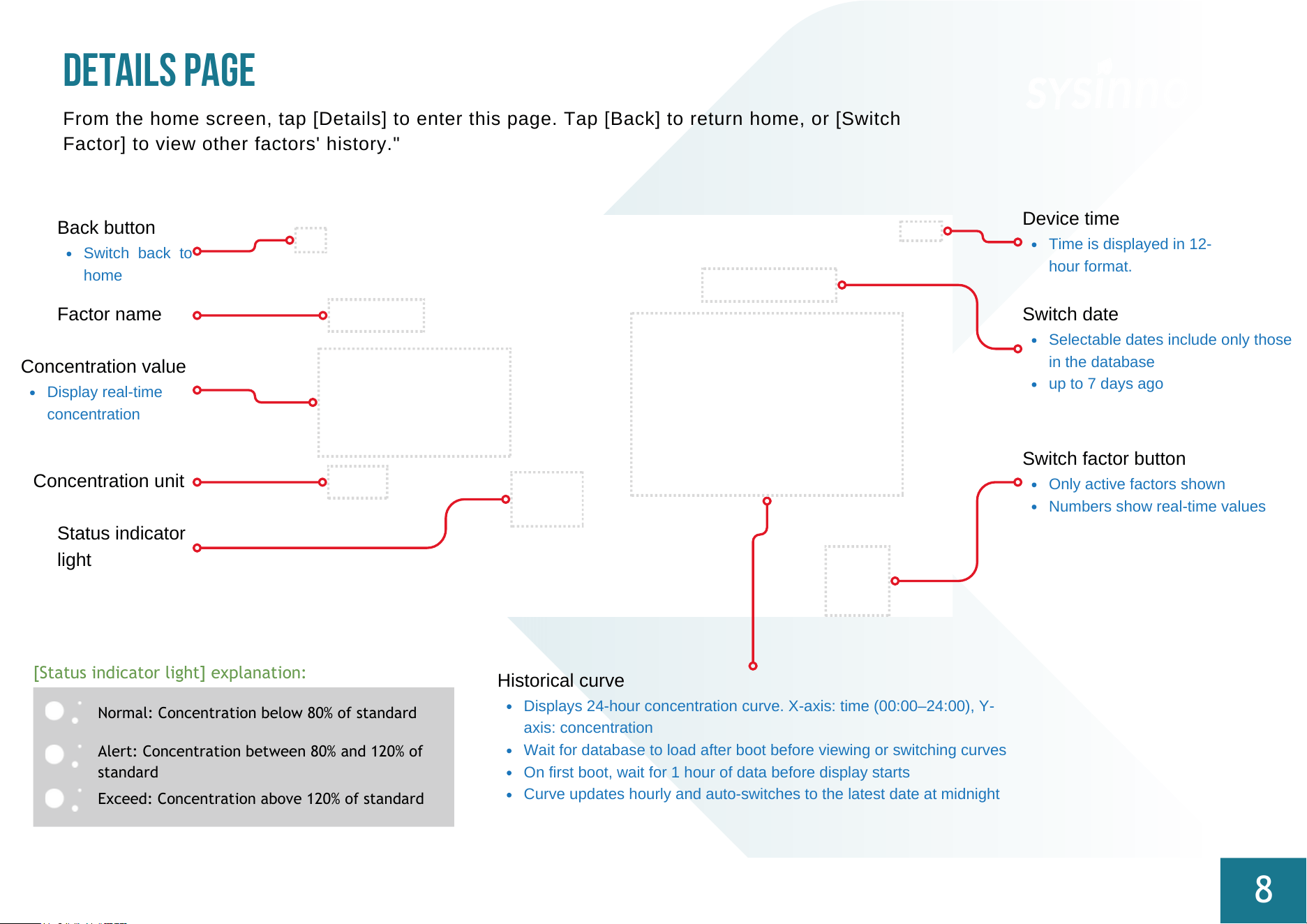
Concentration unit
Back button
Switch back to
home
DETAILS PAGE
8
From the home screen, tap [Details] to enter this page. Tap [Back] to return home, or [Switch
Factor] to view other factors' history."
Concentration value
Display real-time
concentration
Historical curve
Displays 24-hour concentration curve. X-axis: time (00:00–24:00), Y-
axis: concentration
Wait for database to load after boot before viewing or switching curves
On first boot, wait for 1 hour of data before display starts
Curve updates hourly and auto-switches to the latest date at midnight
Factor name
Switch factor button
Only active factors shown
Numbers show real-time values
Switch date
Selectable dates include only those
in the database
up to 7 days ago
Exceed: Concentration above 120% of standard
Alert: Concentration between 80% and 120% of
standard
Normal: Concentration below 80% of standard
[Status indicator light] explanation:
Status indicator
light
Device time
Time is displayed in 12-
hour format.
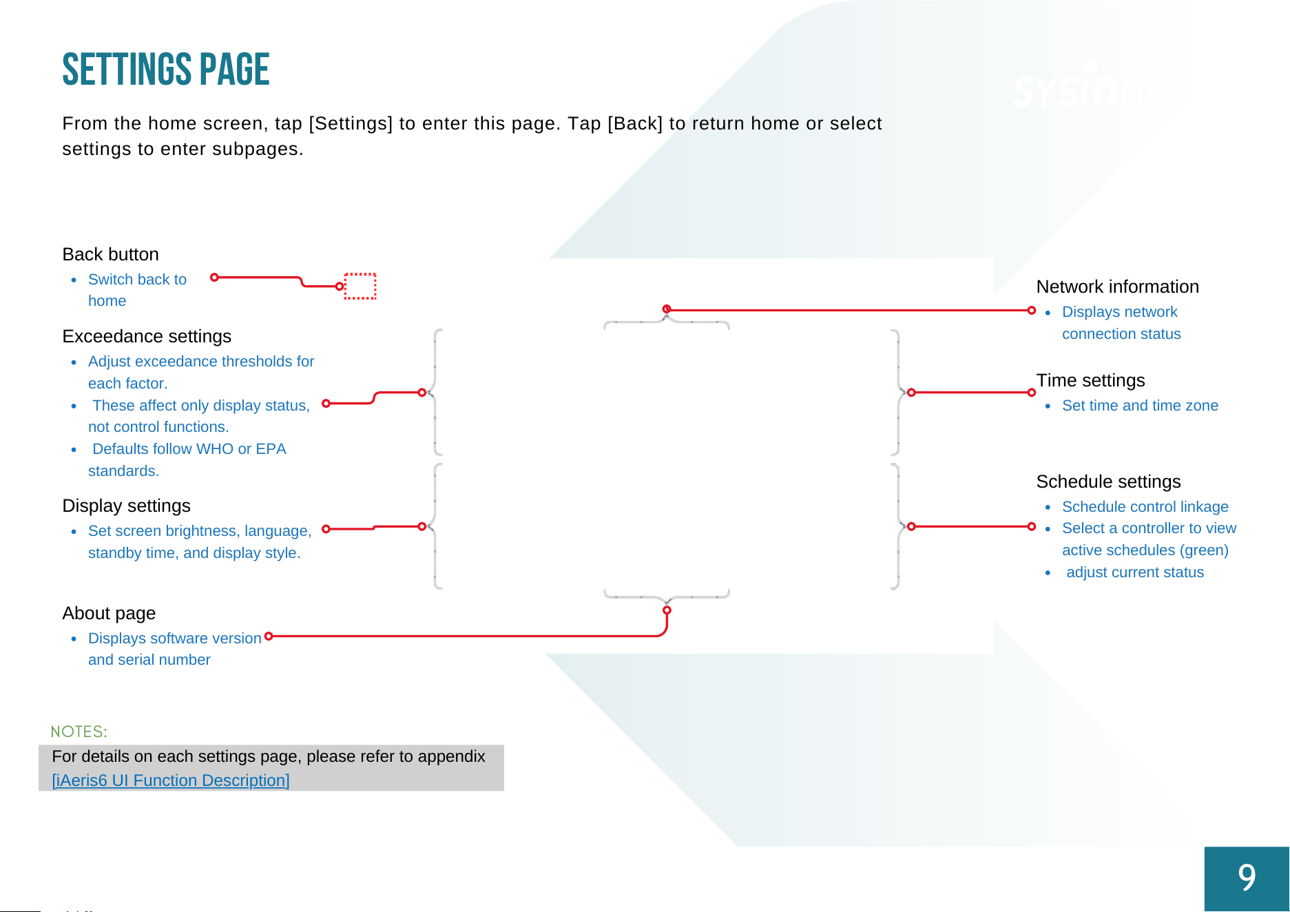
Back button
Switch back to
home
SETTINGS PAGE
9
From the home screen, tap [Settings] to enter this page. Tap [Back] to return home or select
settings to enter subpages.
Exceedance settings
Adjust exceedance thresholds for
each factor.
These affect only display status,
not control functions.
Defaults follow WHO or EPA
standards.
Display settings
Set screen brightness, language,
standby time, and display style.
About page
Displays software version
and serial number
Network information
Displays network
connection status
Time settings
Set time and time zone
Schedule settings
Schedule control linkage
Select a controller to view
active schedules (green)
adjust current status
NOTES:
For details on each settings page, please refer to appendix
[iAeris6 UI Function Description]
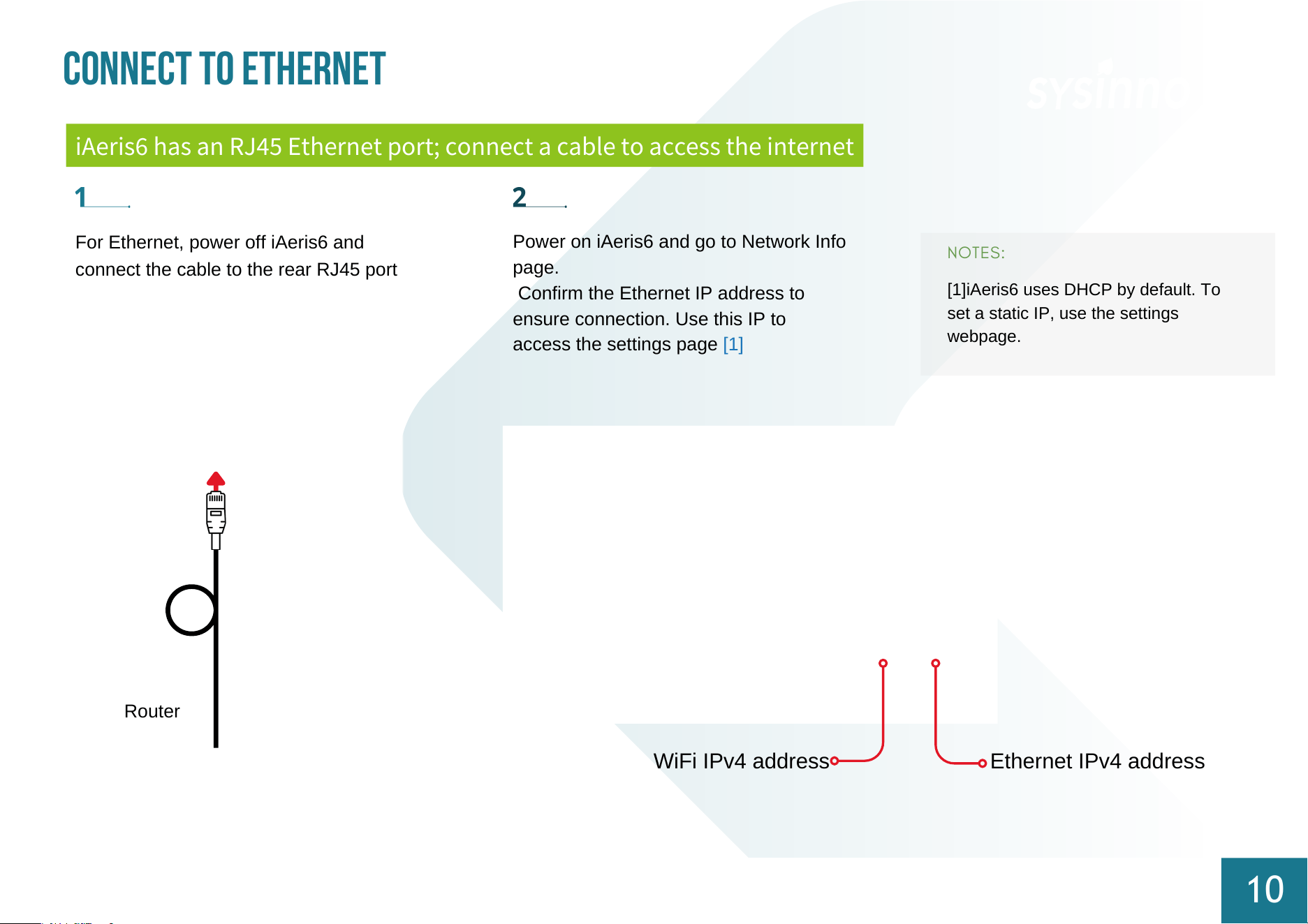
[1]iAeris6 uses DHCP by default. To
set a static IP, use the settings
webpage.
NOTES:
For Ethernet, power off iAeris6 and
connect the cable to the rear RJ45 port
Connect to Ethernet
10
Power on iAeris6 and go to Network Info
page.
Confirm the Ethernet IP address to
ensure connection. Use this IP to
access the settings page [1]
Router
iAeris6 has an RJ45 Ethernet port; connect a cable to access the internet
WiFi IPv4 address Ethernet IPv4 address
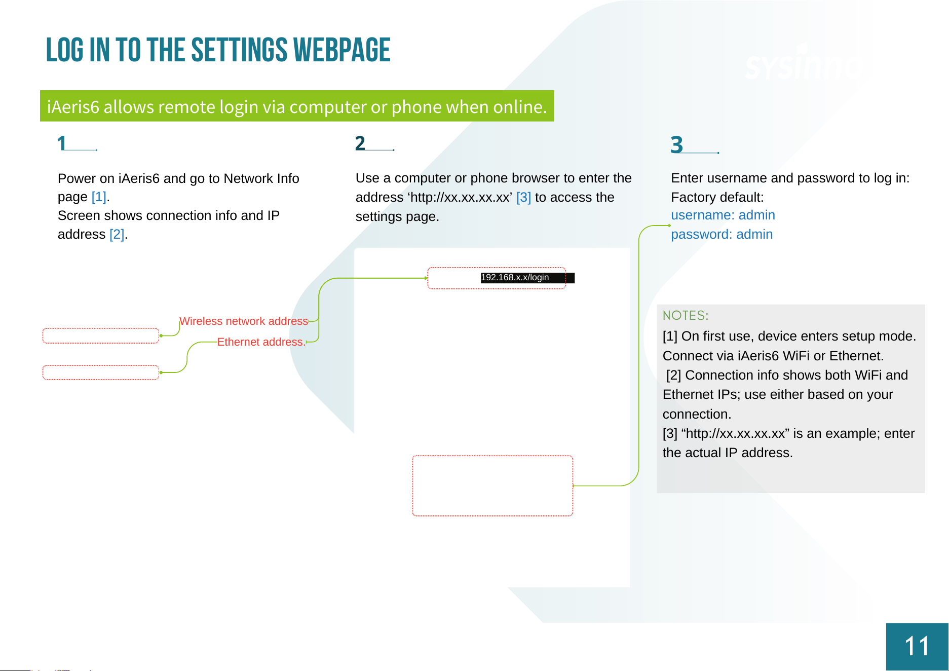
Use a computer or phone browser to enter the
address ‘http://xx.xx.xx.xx’ [3] to access the
settings page.
[1] On first use, device enters setup mode.
Connect via iAeris6 WiFi or Ethernet.
[2] Connection info shows both WiFi and
Ethernet IPs; use either based on your
connection.
[3] “http://xx.xx.xx.xx” is an example; enter
the actual IP address.
NOTES:
Wireless network address
192.168.x.x/login
Log in to the settings webpage
11
iAeris6 allows remote login via computer or phone when online.
Enter username and password to log in:
Factory default:
username: admin
password: admin
Ethernet address.
Power on iAeris6 and go to Network Info
page [1].
Screen shows connection info and IP
address [2].
WiFi Setup Process
12
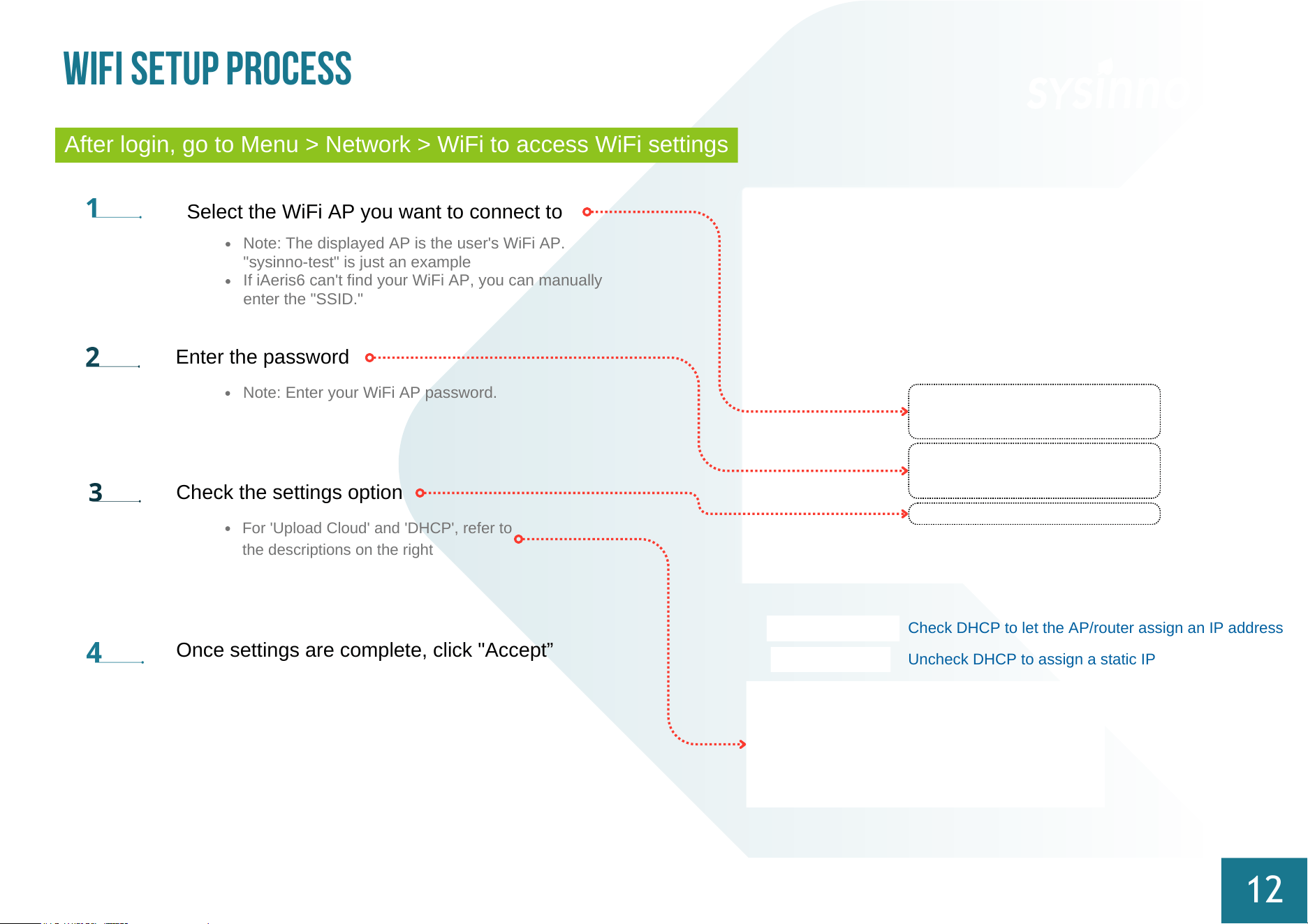
After login, go to Menu > Network > WiFi to access WiFi settings
Select the WiFi AP you want to connect to
Check the settings option
Note: The displayed AP is the user's WiFi AP.
"sysinno-test" is just an example
If iAeris6 can't find your WiFi AP, you can manually
enter the "SSID."
Note: Enter your WiFi AP password.
For 'Upload Cloud' and 'DHCP', refer to
the descriptions on the right
Enter the password
Once settings are complete, click "Accept”
Check DHCP to let the AP/router assign an IP address
Uncheck DHCP to assign a static IP
NOTES:
13
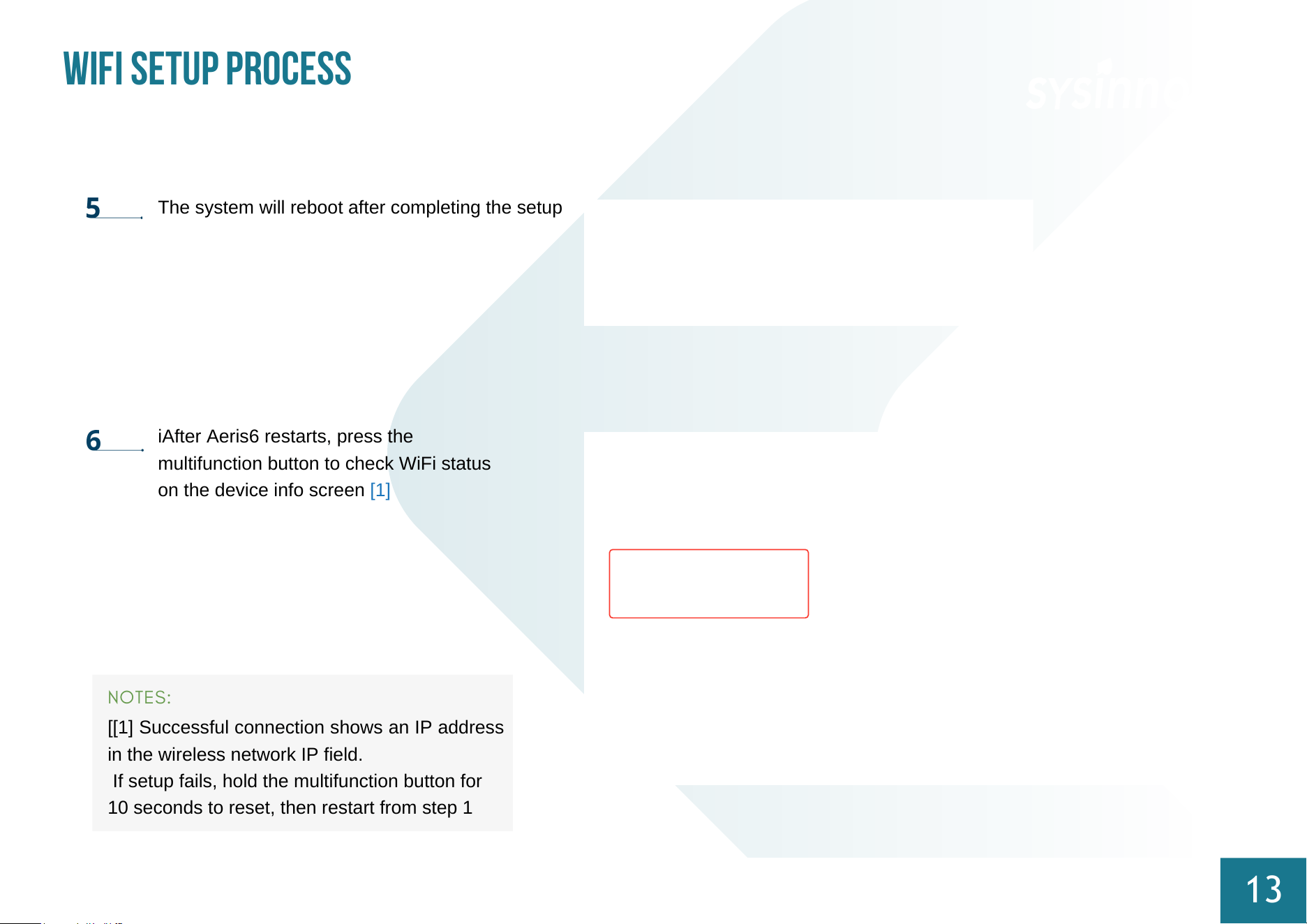
The system will reboot after completing the setup
iAfter Aeris6 restarts, press the
multifunction button to check WiFi status
on the device info screen [1]
WiFi Setup Process
[[1] Successful connection shows an IP address
in the wireless network IP field.
If setup fails, hold the multifunction button for
10 seconds to reset, then restart from step 1
15
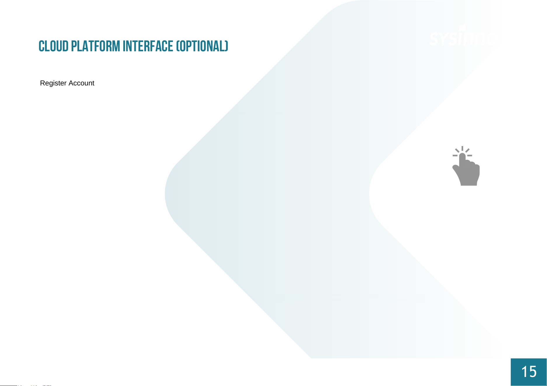
Register Account
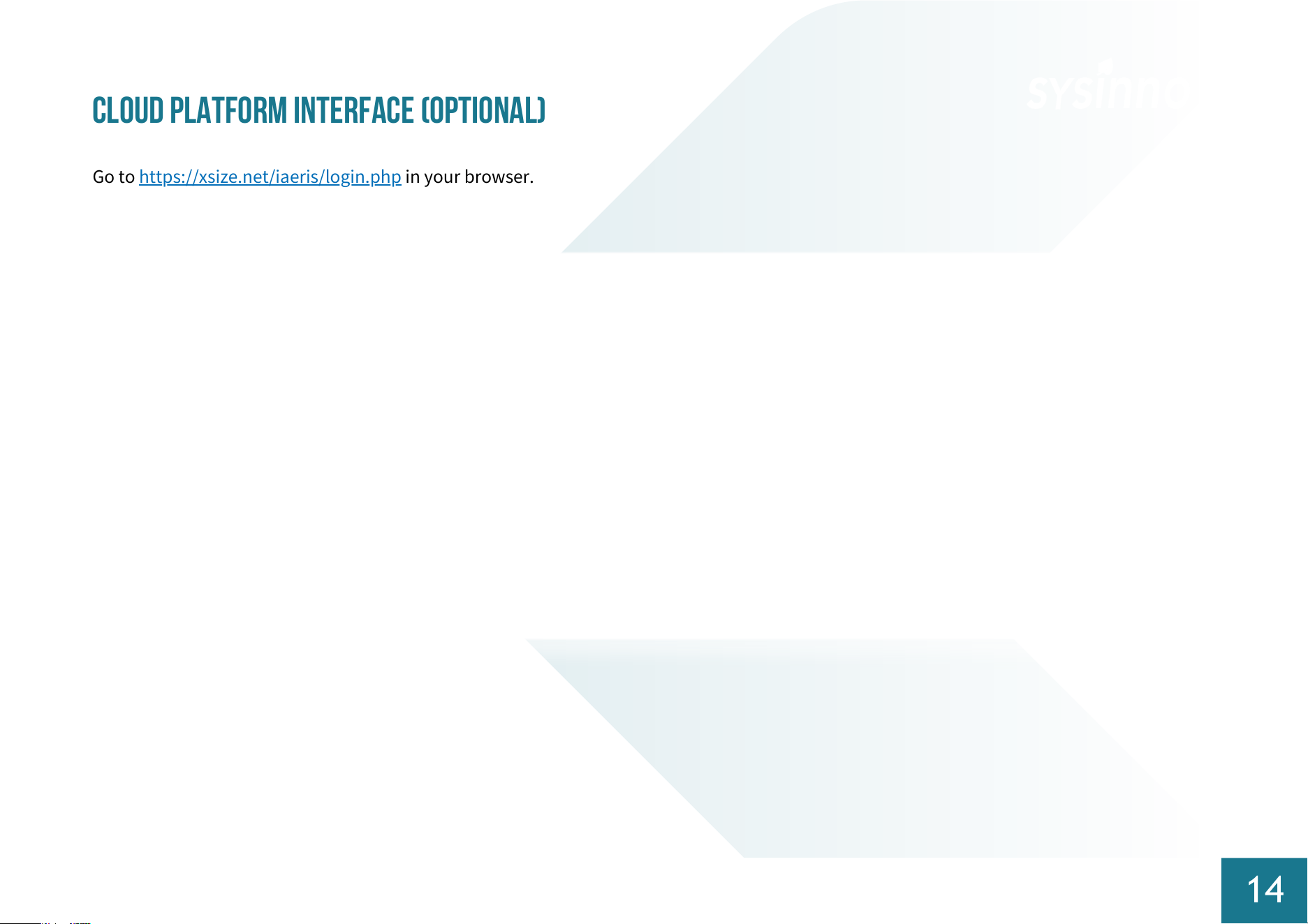
Cloud Platform Interface (Optional)
Cloud Platform Login Homepage
16
After registration and login, view the environmental detection values of the selected device
Data uploads to the cloud platform every six minutes
Historical Data Trend Curve
17
Click "Environmental Factors" on the homepage to access the
historical curve interface.
This page shows hourly averages and up to seven days of data.
18
The cloud platform provides customer-oriented features for easy data recording and management.
Before service expires, contact the device vendor to purchase additional usage years for continued data download functionality.
Customer Area Functionality
Installation Position Recommendations
19
For accuracy, we recommend installing one detector for every 200 square meters of enclosed
space.
For example:
Each open space of 200 square meters requires one detector.
Each individual partitioned meeting room or space requires one detector.
For spaces larger than 200 square meters, consider installing multiple detectors throughout the
entire area to achieve optimal coverage.
Detectors should be installed near indoor areas where people are active or near ventilation (air
conditioning) equipment return air vents.
We recommend installing the detector at a height of 1.5 meters to 2.5 meters.
Position the detector at least 2 meters away from doors, windows, and air vents.
Ensure that the device's ventilation holes are not obstructed, allowing for proper airflow.
To ensure accuracy and longevity, ceiling-mounted installation on the ceiling is not
recommended.
Precautions
20
This product provides general indoor air quality information only and is not intended to determine individual health impacts or serve as a
fire alarm.
Keep the product away from heat sources and areas prone to water splashes or dripping.
Avoid using the product in environments with vibrations or direct sunlight.
Ensure proper airflow by not blocking the ventilation holes around the device.
Do not insert external objects into the ventilation holes to prevent sensor malfunction or electric shock.
Non-technical personnel should not attempt to disassemble, modify, or repair the product.
Use correct connectors and cables during installation and avoid forcing connectors into ports to prevent damage not covered by
warranty.
【
Attention
】
Power Supply Notice:
This product operates on a 12-24V DC
power supply. You can either convert AC
power to the required voltage or use the
provided power adapter.
【
Attention
】
This product supports energy recovery ventilation
(ERV) and single-directional intake fans. Before
purchasing, consult local distributors for
compatibility and technical support.
The control logic for RS485 or dry contact output
is fixed and intended only for ventilation
equipment control.
Use the correct connectors and ports
Avoid forcing connections. Check for
obstructions. Ensure proper alignment.
Damage from mishandling, like inserting wrong
pins, isn't covered by warranty.
Power Supply Specifications:
This product can be powered by the included
an adapter or a 24VDC power source. The
included transformer outputs 5V via a Micro
USB connector. If using a 24VDC power
source, convert mains power to 12-24V before
wiring it to the rear port.
Dry Contact Specifications:
The dry contact is a passive NO switch. AC
rated voltage withstands 125V at 0.3A, and DC
withstands 30V at 1A.
Prohibition of Hot Wiring
When changing the power source or port
terminals, be sure to cut off power before wiring
adjustments, and reconnect power only after
completing the setup.

Federal Communications Commission (FCC) Statement
21
This device complies with Part 15 of the FCC Rules. Operation is subject to the following two conditions:
1.This device may not cause harmful interference, and
2.This device must accept any interference received, including interference that may cause undesired operation.
Class B Equipment Notice
This equipment has been tested and found to comply with the limits for a Class B digital device, pursuant to Part 15 of the FCC Rules.
These limits are designed to provide reasonable protection against harmful interference in a residential installation. This equipment
generates, uses, and can radiate radio frequency energy and, if not installed and used in accordance with the instructions, may cause
harmful interference to radio communications. However, there is no guarantee that interference will not occur in a particular installation.
If this equipment does cause harmful interference to radio or television reception, which can be determined by turning the equipment off
and on, the user is encouraged to try to correct the interference by one or more of the following measures:
Reorient or relocate the receiving antenna.
Increase the separation between the equipment and receiver.
Connect the equipment into an outlet on a circuit different from that to which the receiver is connected.
Consult the dealer or an experienced radio/TV technician for help.
FCC Caution
Any changes or modifications not expressly approved by the party responsible for compliance could void the user’s authority to
operate this equipment.
This transmitter must not be co-located or operating in conjunction with any other antenna or transmitter.
RF Exposure Warning
This equipment complies with FCC radiation exposure limits set forth for an uncontrolled environment. This equipment should
be installed and operated with a minimum distance of 20 cm between the radiator and your body.
appendix: iAeris6 UI Function Description
22
Contents
1.Home Page
Function Description
Button Description
Other Details
2.Sensor Factor Details
Function Description
Button Description
Other Details
3.Options Page
Exceedance Setting
Network Information
Time Setting
Display Setting
About Page
Schedule Setting
Control Page
Schedule List
Schedule Detail Setting
4. Advanced Settings
Function Description
Button Description
Sub Unit Settings
Sub Unit Functions and Modes
Sub Unit Sensors
Sub Unit Controllers
Sub Unit Controller - Advanced
Linking Settings
Sub Unit Controller - Linked Devices
Sub Unit Controller - Linked Sensor
Factor List
Sub Unit Controller - Linked Sensor
Factor Parameters
Function Item
Description
Sensor Value Display
Displays the values of each sensing factor according to the number of sensors set on the current device.
AQI Status Display
The color of the fan-shaped gauge changes based on the set AQI threshold values.
Factor Display
Arrangement
The number of sensing factors shown on the right side changes according to the settings. Each page can display up to five
factors, arranged sequentially.
1. Home Page
23
Function Description
Red / Exceeded: Greater than 120% of the set threshold value (AQI: 201 ~ 500)
Orange / Warning: Between 80% and 120% of the set threshold value (AQI: 101 ~ 200)
Green / Normal: Less than 80% of the set threshold value (AQI: 0 ~ 100)
AQI and Sensor Factor Status Color Description
Button
Name
Function Description
Dropdown Menu –
Display Device
Select which device’s sensor data will be shown on the “Home” and “Sensor
Factor Details” pages.
• The options include only currently connected devices.
• If no sub-devices are connected, this button will automatically disappear.
Menu
Switches the page to the “Options” page.
Sensor Factor
Details Button
Switches the page to the “Sensor Factor History Data” page.
Factor Swipe
Switches the sensor factors displayed on the Home page. When there are
more than five sensor factors, you can swipe left or right in the factor area to
view other sensor factors.
24
Button Description
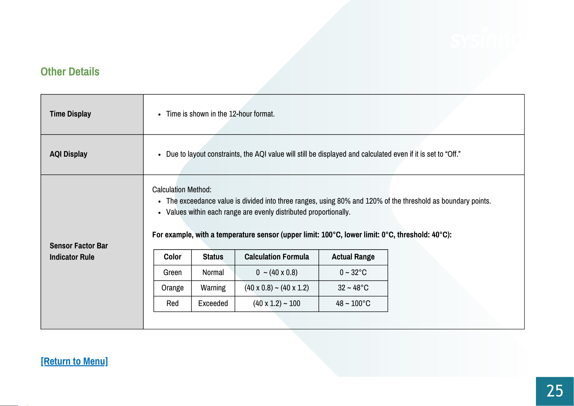
Time Display
Time is shown in the 12-hour format.
AQI Display
Due to layout constraints, the AQI value will still be displayed and calculated even if it is set to “Off.”
Sensor Factor Bar
Indicator Rule
Calculation Method:
The exceedance value is divided into three ranges, using 80% and 120% of the threshold as boundary points.
Values within each range are evenly distributed proportionally.
For example, with a temperature sensor (upper limit: 100°C, lower limit: 0°C, threshold: 40°C):
Color
Status
Calculation Formula
Actual Range
Green
Normal
0 ~ (40 x 0.8)
0 ~ 32°C
Orange
Warning
(40 x 0.8) ~ (40 x 1.2)
32 ~ 48°C
Red
Exceeded
(40 x 1.2) ~ 100
48 ~ 100°C
25
Other Details
[Return to Menu]
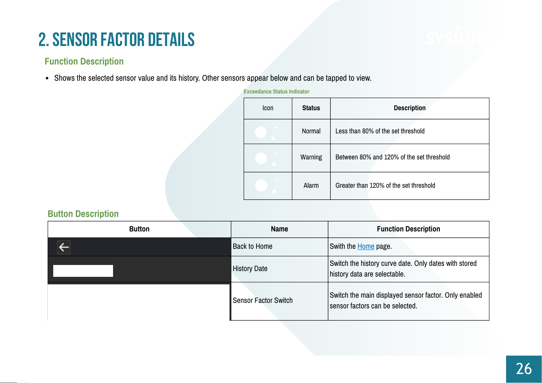
Icon
Status
Description
Normal
Less than 80% of the set threshold
Warning
Between 80% and 120% of the set threshold
Alarm
Greater than 120% of the set threshold
Exceedance Status Indicator
Button
Name
Function Description
Back to Home
Swith the Home page.
History Date
Switch the history curve date. Only dates with stored
history data are selectable.
Sensor Factor Switch
Switch the main displayed sensor factor. Only enabled
sensor factors can be selected.
2. Sensor Factor Details
26
Function Description
Shows the selected sensor value and its history. Other sensors appear below and can be tapped to view.
Button Description
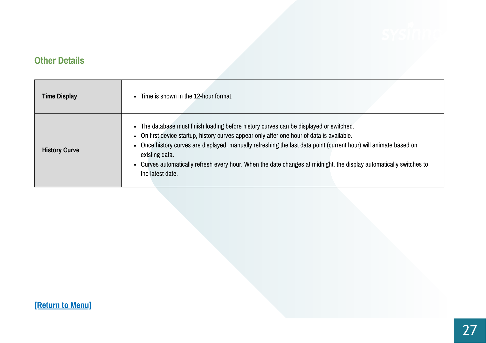
Time Display
Time is shown in the 12-hour format.
History Curve
The database must finish loading before history curves can be displayed or switched.
On first device startup, history curves appear only after one hour of data is available.
Once history curves are displayed, manually refreshing the last data point (current hour) will animate based on
existing data.
Curves automatically refresh every hour. When the date changes at midnight, the display automatically switches to
the latest date.
27
Other Details
[Return to Menu]
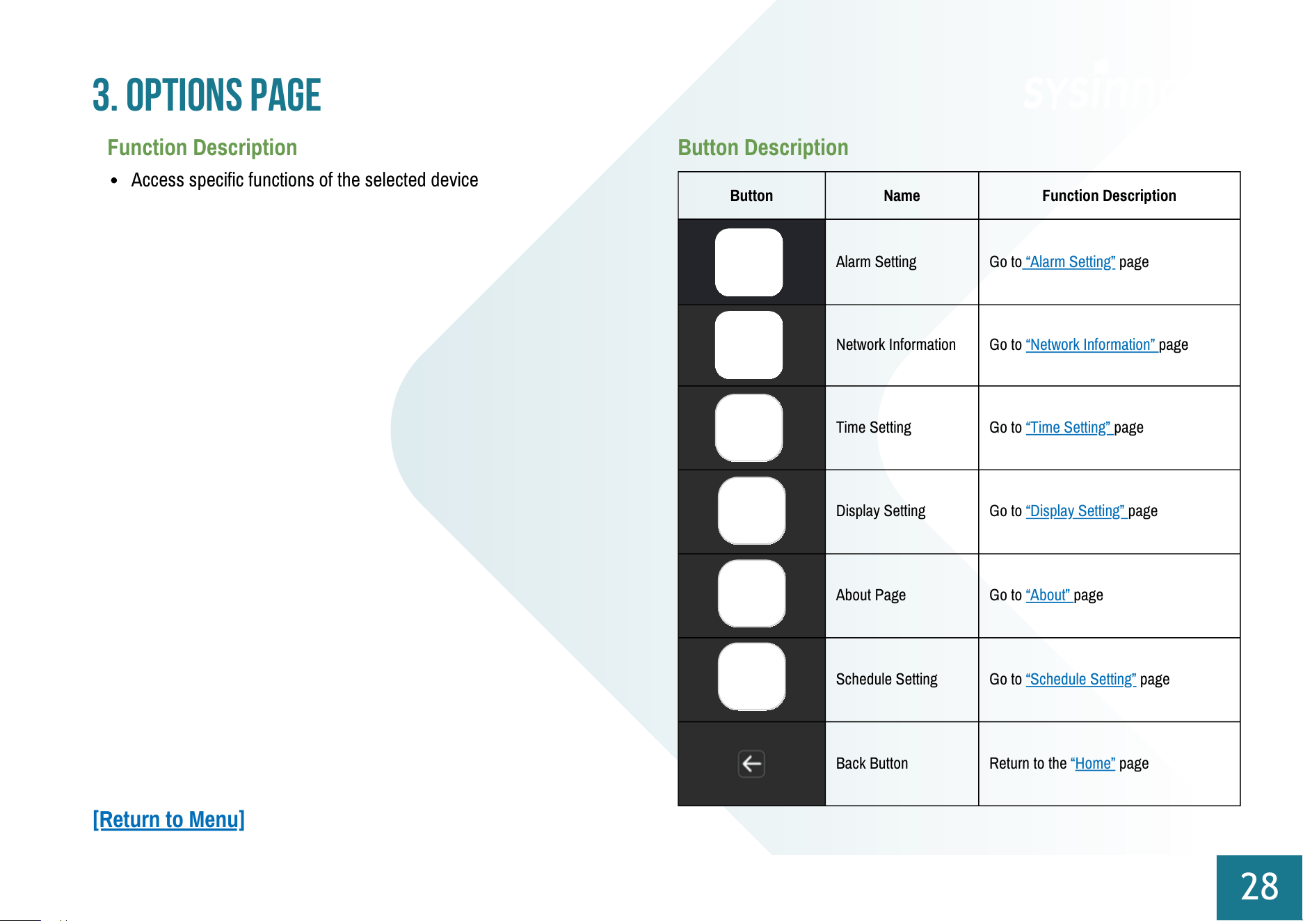
Button
Name
Function Description
Alarm Setting
Go to “Alarm Setting” page
Network Information
Go to “Network Information” page
Time Setting
Go to “Time Setting” page
Display Setting
Go to “Display Setting” page
About Page
Go to “About” page
Schedule Setting
Go to “Schedule Setting” page
Back Button
Return to the “Home” page
3. Options Page
28
Function Description
Access specific functions of the selected device
Button Description
[Return to Menu]
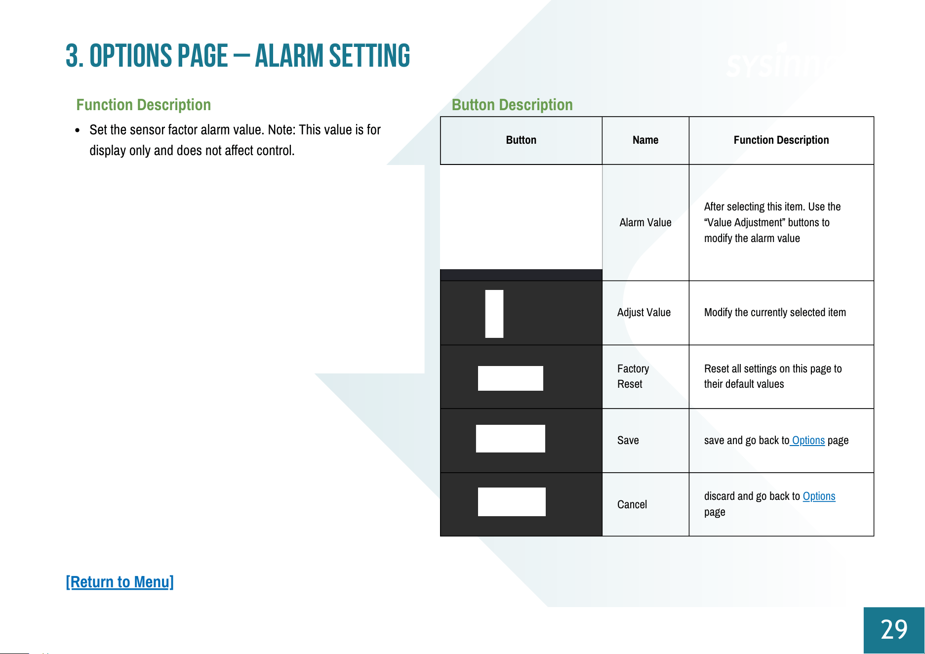
Button
Name
Function Description
Alarm Value
After selecting this item. Use the
“Value Adjustment” buttons to
modify the alarm value
Adjust Value
Modify the currently selected item
Factory
Reset
Reset all settings on this page to
their default values
Save
save and go back to Options page
Cancel
discard and go back to Options
page
3. Options Page – Alarm Setting
29
Function Description
Set the sensor factor alarm value. Note: This value is for
display only and does not affect control.
Button Description
[Return to Menu]
Button
Name
Function Description
Confirm
Back to Options page
3. Options Page – Network Information
30
Function Description
Displays the current device’s network connection status
Button Description
Other Details
Connected WiFi/Ethernet IPs are shown at the bottom-right on QR Core.
If both are disconnected, the page is unavailable from Function Page.
[Return to Menu]
Button
Name
Function Description
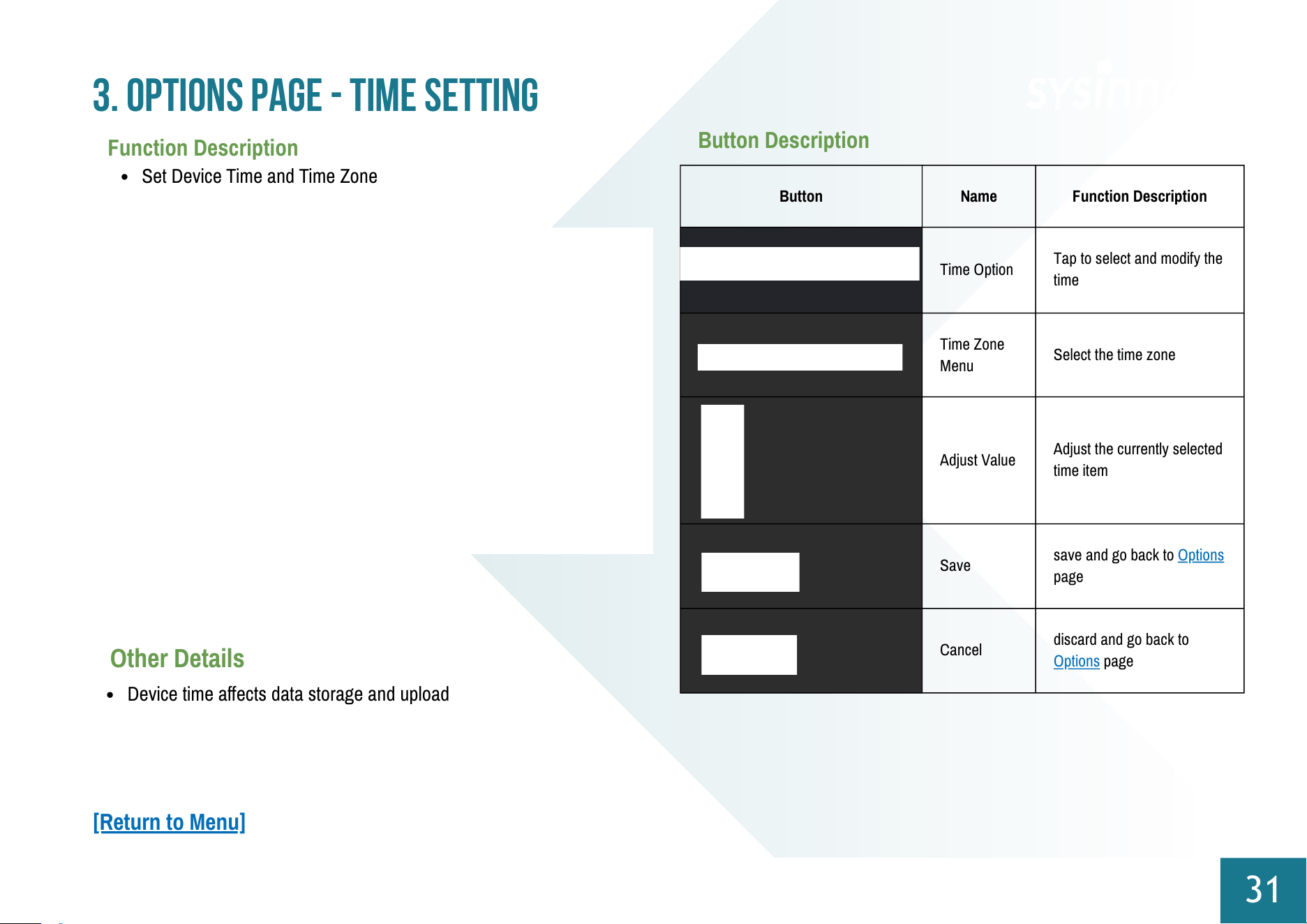
Time Option
Tap to select and modify the
time
Time Zone
Menu
Select the time zone
Adjust Value
Adjust the currently selected
time item
Save
save and go back to Options
page
Cancel
discard and go back to
Options page
Set Device Time and Time Zone
3. Options Page - Time Setting
31
Function Description
Button Description
Other Details
Device time affects data storage and upload
[Return to Menu]
Button
Name
Function Description
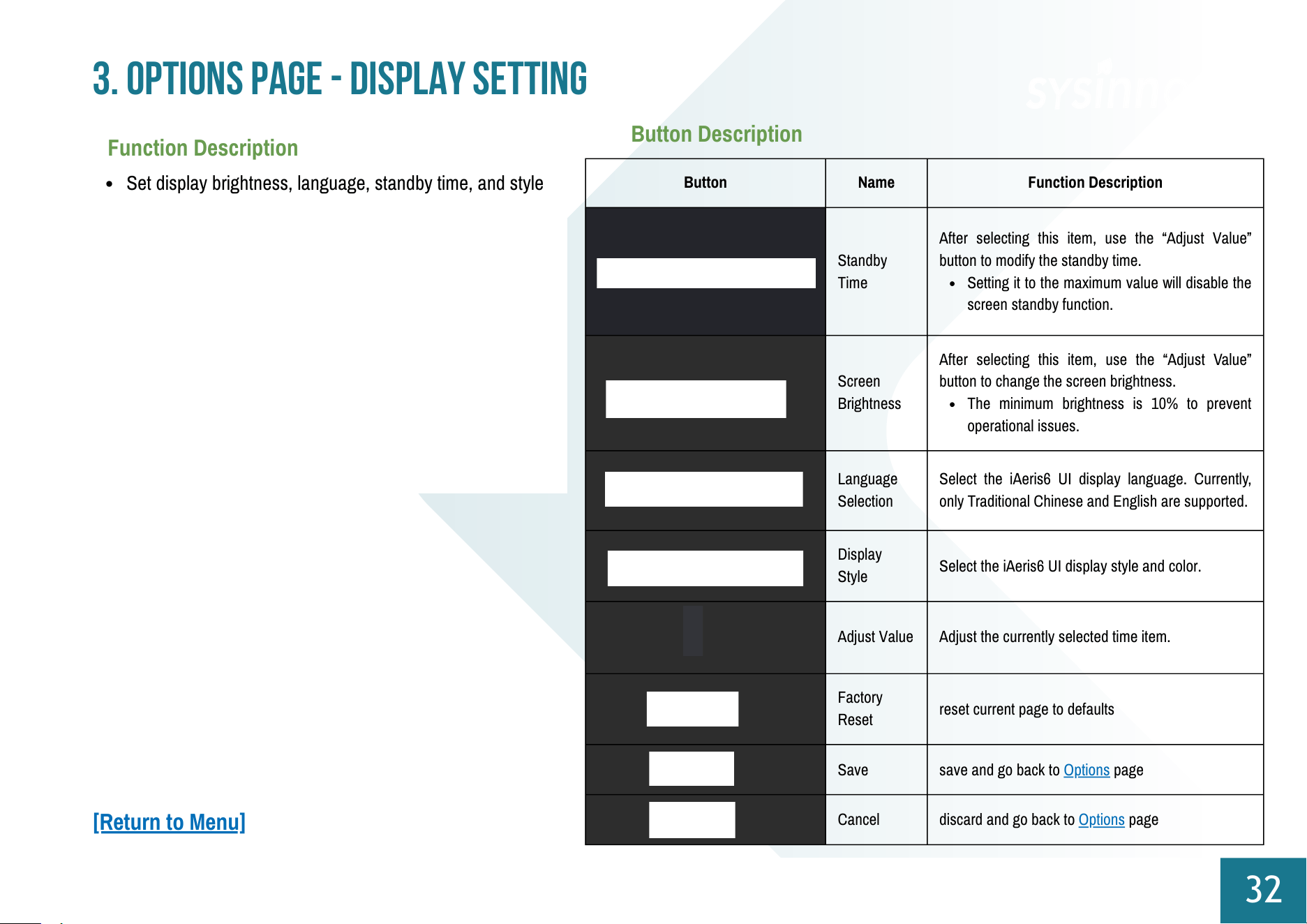
Standby
Time
After selecting this item, use the “Adjust Value”
button to modify the standby time.
Setting it to the maximum value will disable the
screen standby function.
Screen
Brightness
After selecting this item, use the “Adjust Value”
button to change the screen brightness.
The minimum brightness is 10% to prevent
operational issues.
Language
Selection
Select the iAeris6 UI display language. Currently,
only Traditional Chinese and English are supported.
Display
Style
Select the iAeris6 UI display style and color.
Adjust Value
Adjust the currently selected time item.
Factory
Reset
reset current page to defaults
Save
save and go back to Options page
Cancel
discard and go back to Options page
3. Options Page - Display Setting
32
Function Description
Set display brightness, language, standby time, and style
Button Description
[Return to Menu]
Button
Name
Function Description
Controller
Switch
Turn the selected controller on or off
Controller
Schedule
Go to the confirmation page, then return to the
"Schedule List"
Confirm
Return to the "Options Page"
3. Options Page - Schedule Setting
34
Function Description
Select a control device to view active schedules
(green) and adjust controller on/off status.
Button Description
Control Page
[Return to Menu]
Button
Name
Function Description
Controller Switch
Turn the selected controller on or off.
Edit
Go to "Schedule Detail Setting"
to edit an
existing schedule
Delete
Delete the selected schedule (changes apply after
saving)
Add
Go to "Schedule Detail Setting"
to create a new
schedule
Cancel
Discard current settings and return to the Control
Page.
Save
Save current settings and return to the Control
Page.
3. Options Page - Schedule Setting
35
Function Description
Lists all schedules for the selected controller; use buttons to
Add, Edit, or Delete.
Button Description
Schedule List
[Return to Menu]
Button
Name
Function Description
Start Time
Set the start time for the selected schedule using
the “Adjust Value” button.
End Time
Set the end time for the selected schedule using
the “Adjust Value” button.
Select Days
Tap the days of the week on which the current
schedule should repeat.
Adjust
Value
Adjust the value of the currently selected item.
Cancel
Discard current settings and return to the Control
Page.
Save
Save current settings and return to the Control
Page
3. Options Page - Schedule Setting
36
Function Description
Set Start Time, End Time, and Repeat Days for the selected
schedule
Button Description
Schedule Detail Setting
[Return to Menu]
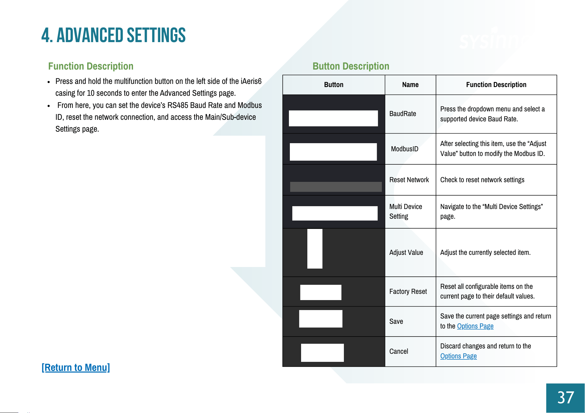
Button
Name
Function Description
BaudRate
Press the dropdown menu and select a
supported device Baud Rate.
ModbusID
After selecting this item, use the “Adjust
Value” button to modify the Modbus ID.
Reset Network
Check to reset network settings
Multi Device
Setting
Navigate to the “Multi Device Settings”
page.
Adjust Value
Adjust the currently selected item.
Factory Reset
Reset all configurable items on the
current page to their default values.
Save
Save the current page settings and return
to the
Options Page
Cancel
Discard changes and return to the
Options Page
4. Advanced Settings
37
Function Description
Press and hold the multifunction button on the left side of the iAeris6
casing for 10 seconds to enter the Advanced Settings page.
From here, you can set the device’s RS485 Baud Rate and Modbus
ID, reset the network connection, and access the Main/Sub-device
Settings page.
Button Description
[Return to Menu]
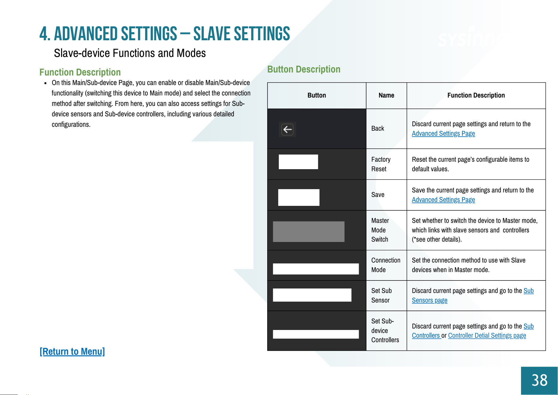
Button
Name
Function Description
Back
Discard current page settings and return to the
Advanced Settings Page
Factory
Reset
Reset the current page’s configurable items to
default values.
Save
Save the current page settings and return to the
Advanced Settings Page
Master
Mode
Switch
Set whether to switch the device to Master mode,
which links with slave sensors and controllers
(*see other details).
Connection
Mode
Set the connection method to use with Slave
devices when in Master mode.
Set Sub
Sensor
Discard current page settings and go to the Sub
Sensors page
Set Sub-
device
Controllers
Discard current page settings and go to the Sub
Controllers or Controller Detial Settings page
4. Advanced Settings – Slave Settings
38
Function Description
On this Main/Sub-device Page, you can enable or disable Main/Sub-device
functionality (switching this device to Main mode) and select the connection
method after switching. From here, you can also access settings for Sub-
device sensors and Sub-device controllers, including various detailed
configurations.
Button Description
Slave-device Functions and Modes
[Return to Menu]
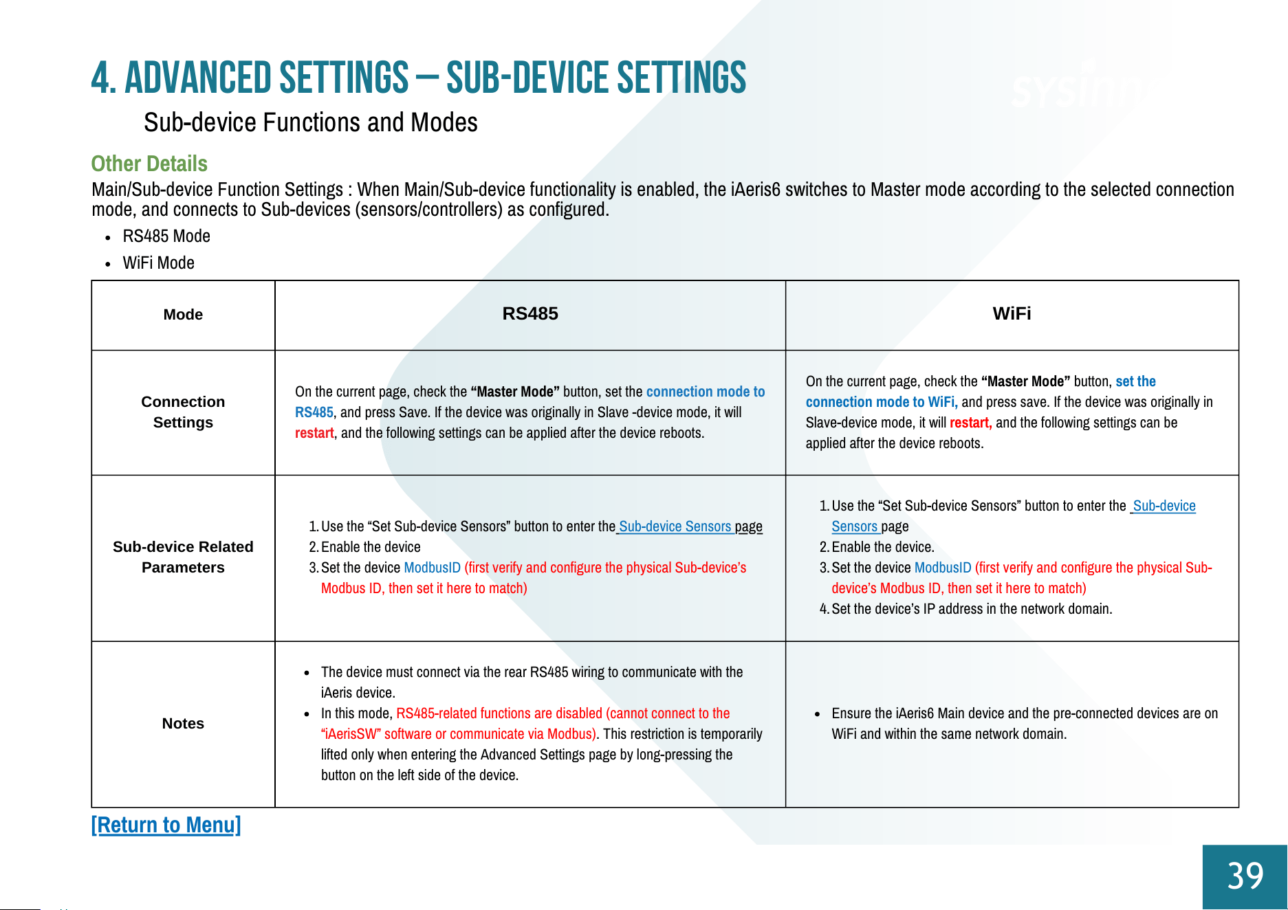
Mode
RS485
WiFi
Connection
Settings
On the current page, check the “Master Mode” button, set the connection mode to
RS485, and press Save. If the device was originally in Slave -device mode, it will
restart, and the following settings can be applied after the device reboots.
On the current page, check the “Master Mode” button, set the
connection mode to WiFi, and press save. If the device was originally in
Slave-device mode, it will restart, and the following settings can be
applied after the device reboots.
Sub-device Related
Parameters
1.Use the “Set Sub-device Sensors” button to enter the Sub-device Sensors page
2.Enable the device
3.Set the device ModbusID (first verify and configure the physical Sub-device’s
Modbus ID, then set it here to match)
1.Use the “Set Sub-device Sensors” button to enter the Sub-device
Sensors page
2.Enable the device.
3.Set the device ModbusID (first verify and configure the physical Sub-
device’s Modbus ID, then set it here to match)
4.Set the device’s IP address in the network domain.
Notes
The device must connect via the rear RS485 wiring to communicate with the
iAeris device.
In this mode, RS485-related functions are disabled (cannot connect to the
“iAerisSW” software or communicate via Modbus). This restriction is temporarily
lifted only when entering the Advanced Settings page by long-pressing the
button on the left side of the device.
Ensure the iAeris6 Main device and the pre-connected devices are on
WiFi and within the same network domain.
4. Advanced Settings – Sub-device Settings
39
Other Details
Sub-device Functions and Modes
Main/Sub-device Function Settings : When Main/Sub-device functionality is enabled, the iAeris6 switches to Master mode according to the selected connection
mode, and connects to Sub-devices (sensors/controllers) as configured.
RS485 Mode
WiFi Mode
[Return to Menu]
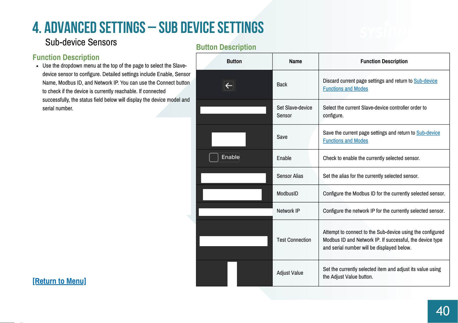
Button
Name
Function Description
Back
Discard current page settings and return to Sub-device
Functions and Modes
Set Slave-device
Sensor
Select the current Slave-device controller order to
configure.
Save
Save the current page settings and return to Sub-device
Functions and Modes
Enable
Check to enable the currently selected sensor.
Sensor Alias
Set the alias for the currently selected sensor.
ModbusID
Configure the Modbus ID for the currently selected sensor.
Network IP
Configure the network IP for the currently selected sensor.
Test Connection
Attempt to connect to the Sub-device using the configured
Modbus ID and Network IP. If successful, the device type
and serial number will be displayed below.
Adjust Value
Set the currently selected item and adjust its value using
the Adjust Value button.
4. Advanced Settings – Sub device Settings
40
Function Description
Use the dropdown menu at the top of the page to select the Slave-
device sensor to configure. Detailed settings include Enable, Sensor
Name, Modbus ID, and Network IP. You can use the Connect button
to check if the device is currently reachable. If connected
successfully, the status field below will display the device model and
serial number.
Button Description
Sub-device Sensors
[Return to Menu]
Button
Name
Function Description
Back
Discard current page settings and return to Sub-device
Functions and Modes
Set Slave-device
Controller
Select the current Slave-device controller order to
configure.
Save
Save the current page settings and return to Sub-device
Functions and Modes
Enable
Check to enable the currently selected controller.
Controller Alias
Set the alias for the currently selected controller.
ModbusID
Configure the Modbus ID for the currently selected
controller.
Network IP
Set the network IP for the currently selected controller.
Test Connection
Attempt to connect to the Slave-device using the
configured Modbus ID and Network IP. If successful,
the device type and serial number will be displayed
below.
Adjust Value
Set the currently selected item and adjust its value
using the Adjust Value button.
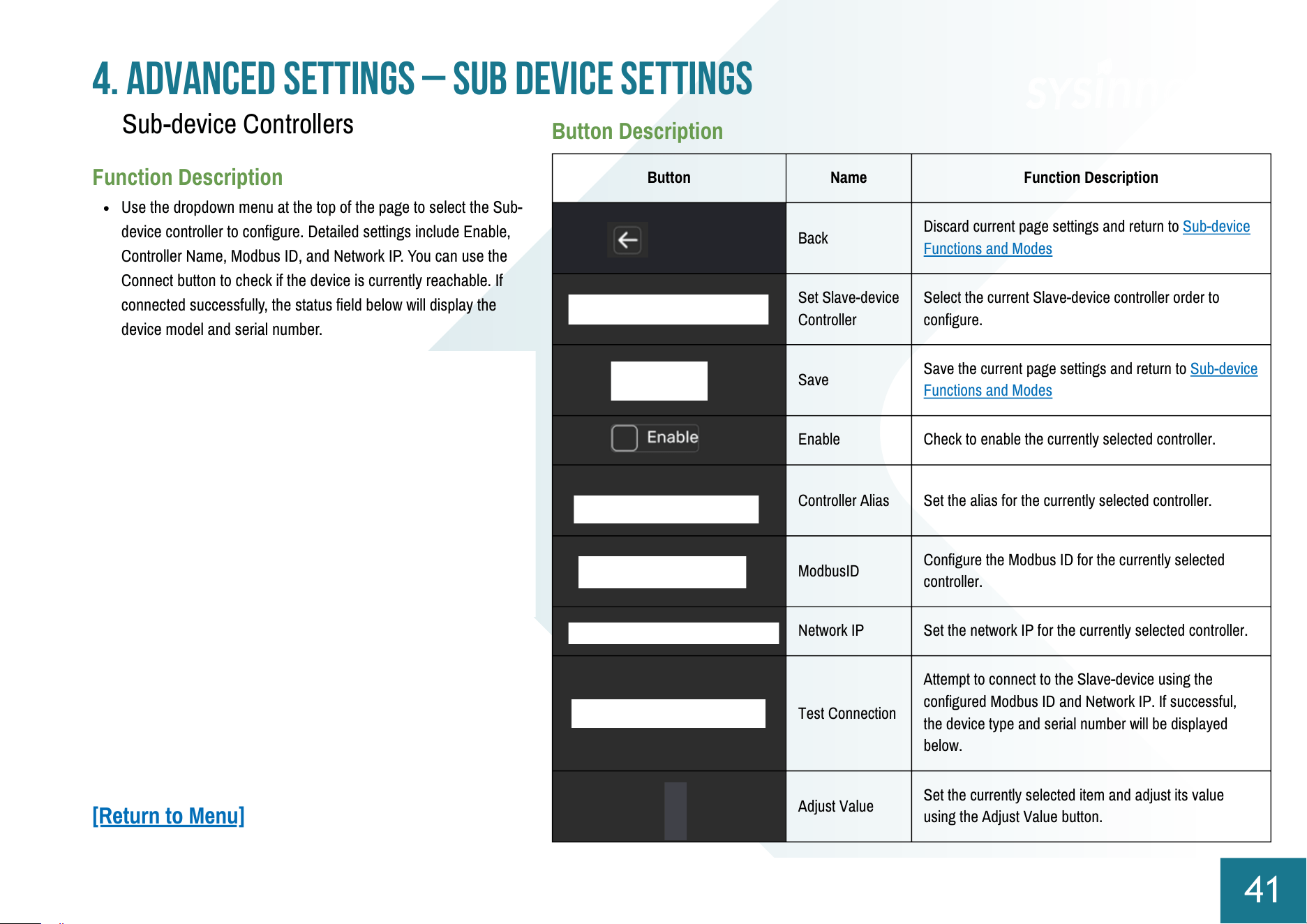
4. Advanced Settings – Sub device Settings
41
Function Description
Use the dropdown menu at the top of the page to select the Sub-
device controller to configure. Detailed settings include Enable,
Controller Name, Modbus ID, and Network IP. You can use the
Connect button to check if the device is currently reachable. If
connected successfully, the status field below will display the
device model and serial number.
Button Description
Sub-device Controllers
[Return to Menu]
Button
Name
Function Description
Back
Discard current page settings and return to
Sub-device Functions and Modes
Set Linked
Controller Switch
Select the current Slave-device controller
switch (dry contact) to configure.
Save
Save the current page settings and return to
Sub-device Functions and Modes.
Switch Alias
Set the alias for the currently selected
controller switch.
On Delay
Set the on-delay time for the currently
selected controller switch.
Off Delay
Set the off-delay time for the currently
selected controller switch.
Activation
Condition
Set the activation logic for the currently
selected controller switch.
Linked Sensors
Set the sensors associated with the
currently selected controller.
Linked Sensor
Factors
Set the sensor factors associated with the
currently selected controller switch.
Adjust Value
Set the currently selected item
and adjust its value using the
Adjust Value button.
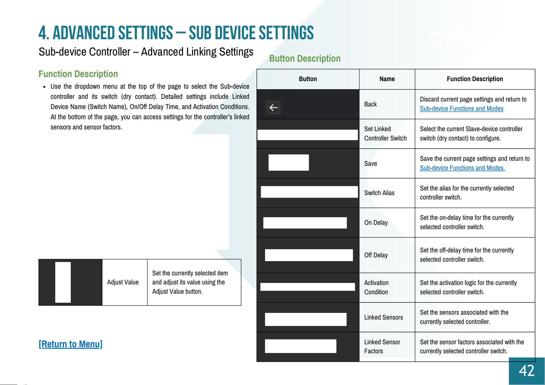
4. Advanced Settings – Sub device Settings
42
Function Description
Use the dropdown menu at the top of the page to select the Sub-device
controller and its switch (dry contact). Detailed settings include Linked
Device Name (Switch Name), On/Off Delay Time, and Activation Conditions.
At the bottom of the page, you can access settings for the controller’s linked
sensors and sensor factors.
Button Description
Sub-device Controller – Advanced Linking Settings
[Return to Menu]
Button
Name
Function Description
Back
Save the current page settings and return to
Sub-device Controller – Advanced Linking
Settings.
Add Linked
Sensor
Add the Sub-device sensor selected from
the dropdown menu to the linking list.
Remove
Linked
Sensor
Delete the selected sensor from the linking
list.
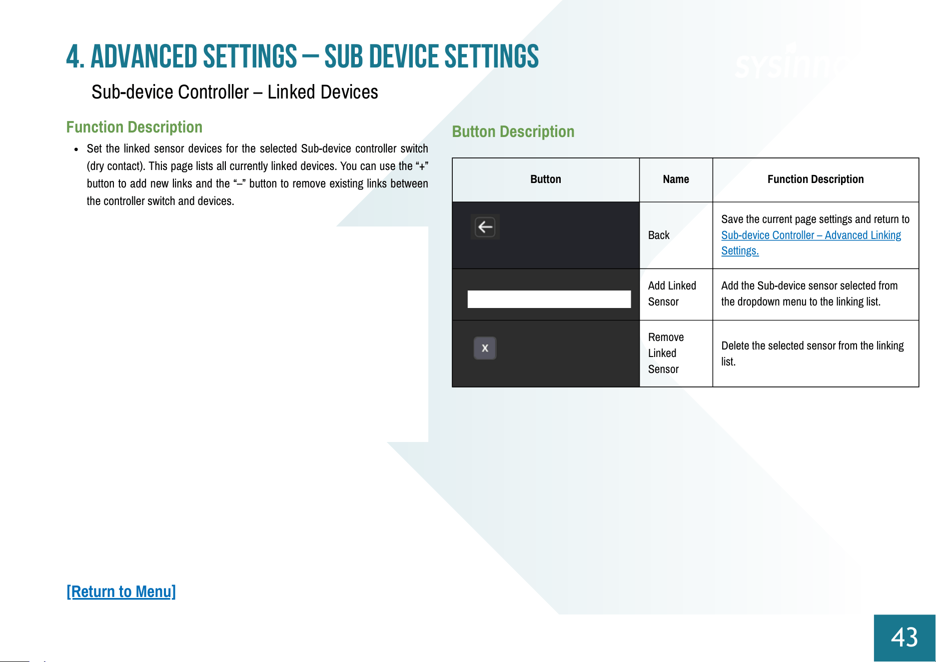
4. Advanced Settings – Sub device Settings
43
Function Description
Set the linked sensor devices for the selected Sub-device controller switch
(dry contact). This page lists all currently linked devices. You can use the “+”
button to add new links and the “–” button to remove existing links between
the controller switch and devices.
Button Description
Sub-device Controller – Linked Devices
[Return to Menu]
Button
Name
Function Description
Back
Save the current page settings and return to
Sub-device Controller – Advanced Linking
Settings
Add
Switch to the [Sub-device Controller – Linked
devices] page. After completing and saving the
settings, the newly configured factor will be
added to the current linked controller switch
list.
Edit
Switch to the [Sub-device Controller – Linked
devices] page. After completing and saving the
settings, the modified factor will update in the
current linked controller switch list.
Delete
Remove the selected sensor factor link from
the current controller switch’s linked factors
list.
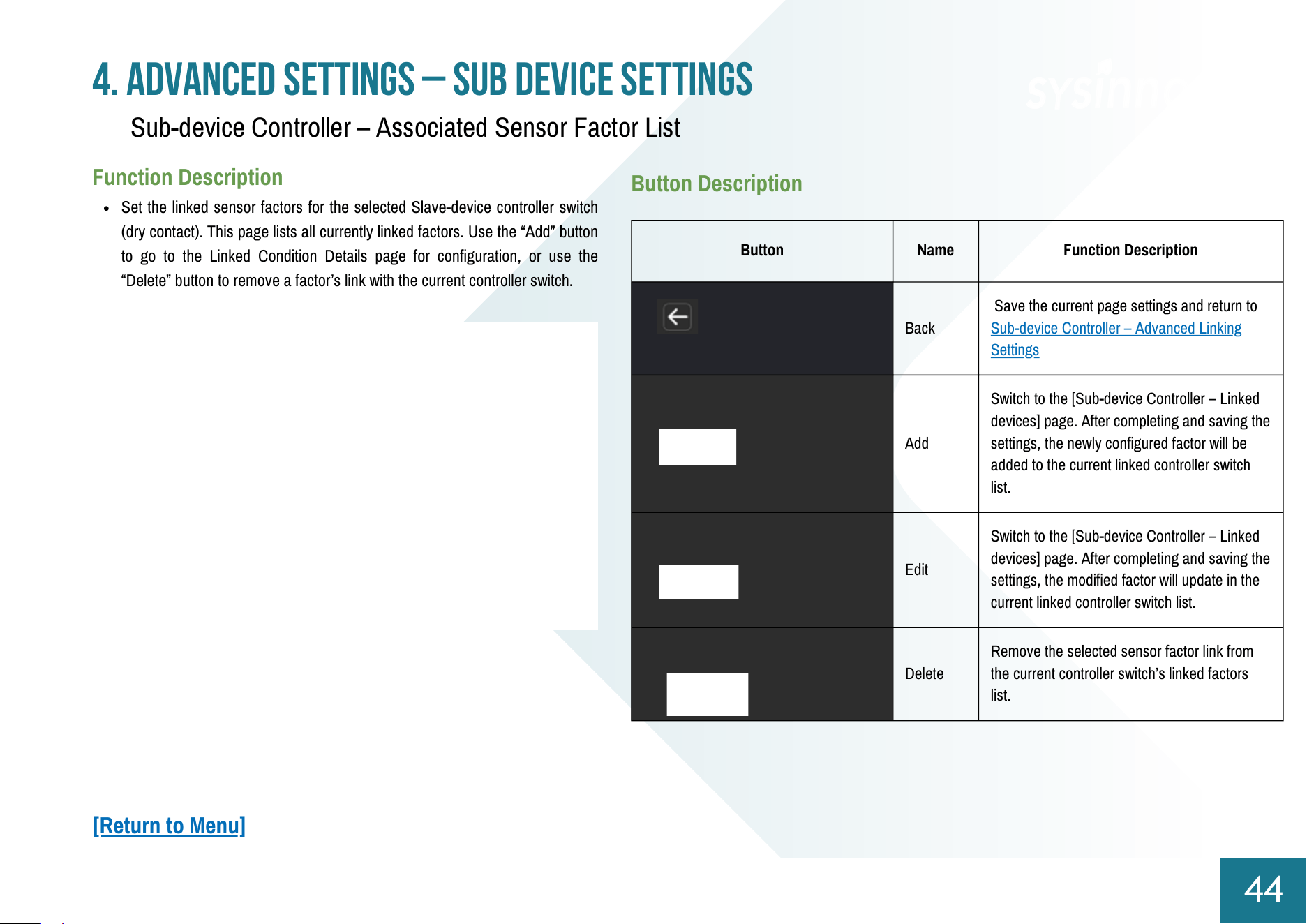
4. Advanced Settings – Sub device Settings
44
Function Description
Set the linked sensor factors for the selected Slave-device controller switch
(dry contact). This page lists all currently linked factors. Use the “Add” button
to go to the Linked Condition Details page for configuration, or use the
“Delete” button to remove a factor’s link with the current controller switch.
Button Description
Sub-device Controller – Associated Sensor Factor List
[Return to Menu]
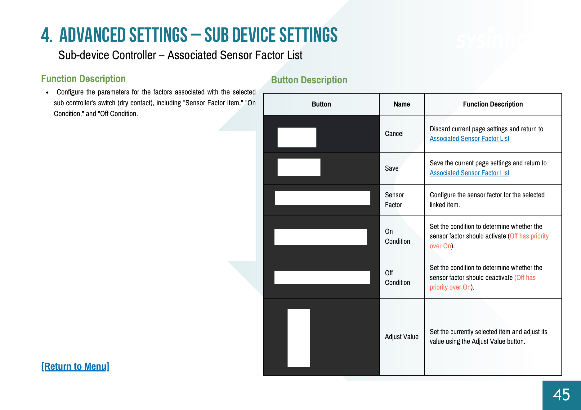
Button
Name
Function Description
Cancel
Discard current page settings and return to
Associated Sensor Factor List
Save
Save the current page settings and return to
Associated Sensor Factor List
Sensor
Factor
Configure the sensor factor for the selected
linked item.
On
Condition
Set the condition to determine whether the
sensor factor should activate (Off has priority
over On).
Off
Condition
Set the condition to determine whether the
sensor factor should deactivate (Off has
priority over On).
Adjust Value
Set the currently selected item and adjust its
value using the Adjust Value button.
4. Advanced Settings – Sub device Settings
45
Function Description
Configure the parameters for the factors associated with the selected
sub controller's switch (dry contact), including "Sensor Factor Item," "On
Condition," and "Off Condition.
Button Description
Sub-device Controller – Associated Sensor Factor List
[Return to Menu]
Appendix: iAeris6 Login Settings
46
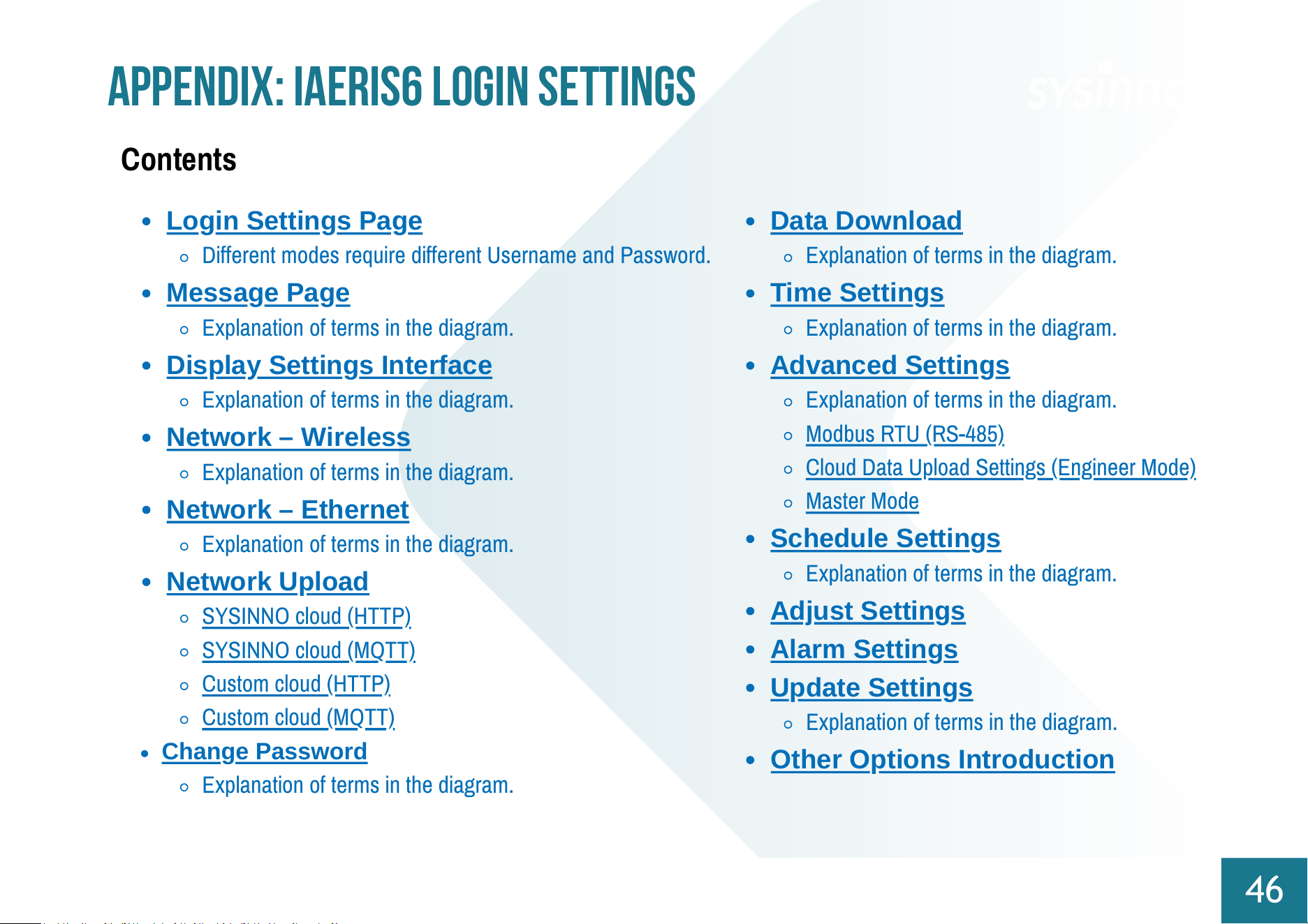
Contents
Login Settings Page
Different modes require different Username and Password.
Message Page
Explanation of terms in the diagram.
Display Settings Interface
Explanation of terms in the diagram.
Network – Wireless
Explanation of terms in the diagram.
Network – Ethernet
Explanation of terms in the diagram.
Network Upload
SYSINNO cloud (HTTP)
SYSINNO cloud (MQTT)
Custom cloud (HTTP)
Custom cloud (MQTT)
Change Password
Explanation of terms in the diagram.
Data Download
Explanation of terms in the diagram.
Time Settings
Explanation of terms in the diagram.
Advanced Settings
Explanation of terms in the diagram.
Modbus RTU (RS-485)
Cloud Data Upload Settings (Engineer Mode)
Master Mode
Schedule Settings
Explanation of terms in the diagram.
Adjust Settings
Alarm Settings
Update Settings
Explanation of terms in the diagram.
Other Options Introduction
Login Settings Page
47
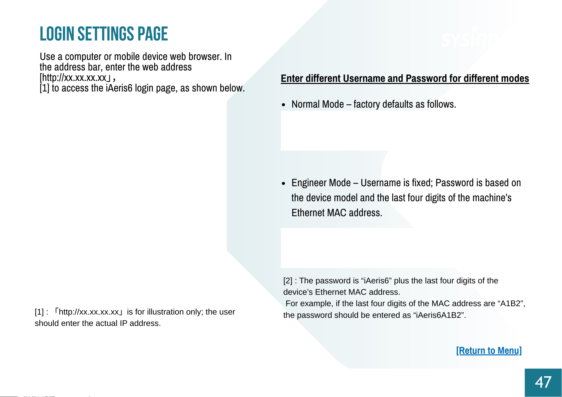
Use a computer or mobile device web browser. In
the address bar, enter the web address
[http://xx.xx.xx.xx
」
,
[1] to access the iAeris6 login page, as shown below.
Enter different Username and Password for different modes
Normal Mode – factory defaults as follows.
[1] :
「
http://xx.xx.xx.xx
」
is for illustration only; the user
should enter the actual IP address.
Engineer Mode – Username is fixed; Password is based on
the device model and the last four digits of the machine’s
Ethernet MAC address.
[2] : The password is “iAeris6” plus the last four digits of the
device’s Ethernet MAC address.
For example, if the last four digits of the MAC address are “A1B2”,
the password should be entered as “iAeris6A1B2”.
[Return to Menu]
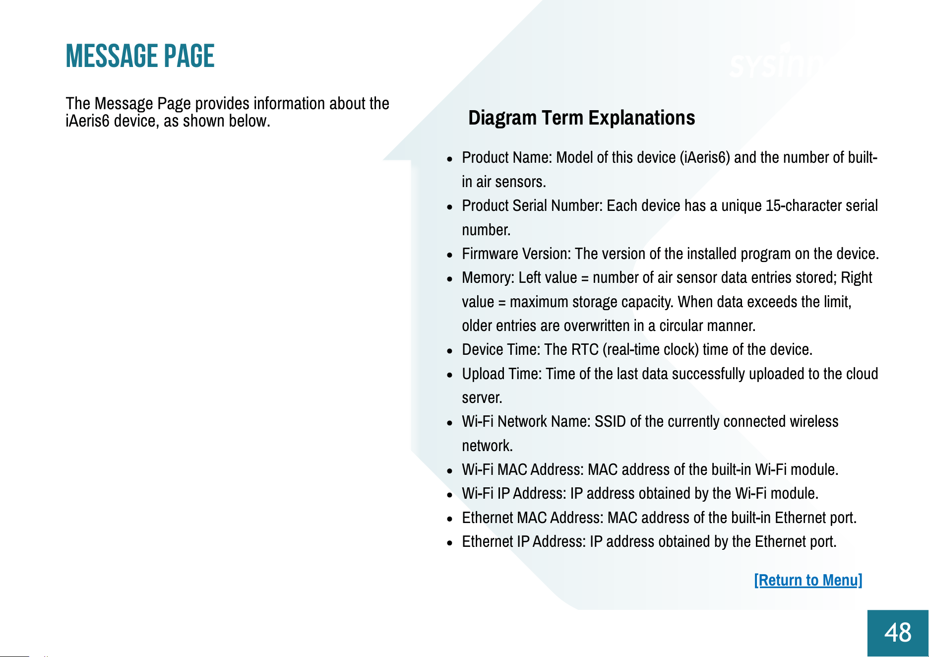
The Message Page provides information about the
iAeris6 device, as shown below.
Diagram Term Explanations
Product Name: Model of this device (iAeris6) and the number of built-
in air sensors.
Product Serial Number: Each device has a unique 15-character serial
number.
Firmware Version: The version of the installed program on the device.
Memory: Left value = number of air sensor data entries stored; Right
value = maximum storage capacity. When data exceeds the limit,
older entries are overwritten in a circular manner.
Device Time: The RTC (real-time clock) time of the device.
Upload Time: Time of the last data successfully uploaded to the cloud
server.
Wi-Fi Network Name: SSID of the currently connected wireless
network.
Wi-Fi MAC Address: MAC address of the built-in Wi-Fi module.
Wi-Fi IP Address: IP address obtained by the Wi-Fi module.
Ethernet MAC Address: MAC address of the built-in Ethernet port.
Ethernet IP Address: IP address obtained by the Ethernet port.
Message Page
48
[Return to Menu]
Network – Wireless
50
This page allows the device’s Wi-Fi module to
connect to an external router. Fill in the required
fields and press Agree to complete the setup.
Wi-Fi Enable: Enable or disable the device’s Wi-Fi module.
Scan Wi-Fi Networks: Lists SSIDs of detectable wireless access
points.
Security Type: Wireless security mode for connecting to the access
point:
WPA/WPA2 Personal: Uses a personal password for
encryption.
WPA/WPA2 Enterprise (PEAP): Typically used in enterprise
environments; requires username and password for
authentication.
Open (No Authentication): No encryption or authentication;
anyone can connect.
DHCP Enable: Enable for automatic IP and network settings from
the access point; disable to manually set a static IP address.
Diagram Term Explanations
[Return to Menu]
Network – Ethernet
51
This page provides settings for the device’s Ethernet
port, as shown below.
Ethernet Enable: Enable or disable the device’s Ethernet port.
DHCP Enable: When enabled, the router automatically assigns IP
and network settings. When disabled, a static IP must be manually
configured.
[Return to Menu]
Diagram Term Explanations
Network Upload
52
This page provides settings for uploading device
data to a cloud server. You can choose different
server modes and communication formats. The
settings are divided into four pages. This function
must be configured in Engineer Mode.
SYSINNO cloud (HTTP)
Using the HTTP protocol, simply enable the setting to upload data to the
cloud server provided by Sysinno, as shown below.
SYSINNO cloud (HTTP)
SYSINNO cloud (MQTT)
Custom cloud (HTTP)
Custom cloud (MQTT)
[Return to Menu]
Network Upload
53
SYSINNO cloud (MQTT)
When using Sysinno On-Premise
Server (i-Cap), simply enable it and set
its IP address. Data can then be easily
uploaded using the MQTT protocol, as
shown below.
Custom cloud (HTTP)
Supports HTTP protocol to push data to
a customer-specified server IP address
and path, as shown below.
Custom cloud (MQTT)
Using MQTT v3 protocol, the device
can send data to a specified MQTT
Broker IP address, Topic, and port. All
related settings are shown in the
diagram below.
[Return to Menu]
Change Password
54
The system allows users to change their account
information, including Username, New Password,
and Confirm Password. The interface is shown
below.
Username: Enter your new login account name.
New Password: Set your new password.
Confirm Password: Re-enter the new password to ensure it
matches the previous field. If the two entries do not match, the
password change cannot be completed.
[Return to Menu]
Diagram Term Explanations
Data Download
55
The system supports downloading stored data via
the web interface, as shown below.
Export Start Time: Select the start date and time for the data
export.
Export End Time: Select the end date and time for the data export.
Data Type:
Raw: Export all original data records.
Per Minute (Average): Export average data per minute.
Per Hour (Average): Export average data per hour.
Per Day (Average): Export average data per day.
Memory: Displays two values: left = current stored entries, right =
maximum storage capacity. When the storage reaches its limit,
older data is overwritten in a circular manner.
[Return to Menu]
Diagram Term Explanations
Time Settings
56
The device system time can be set in two ways:
Network Time or Manual, as shown below.
Time Sync: Choose Automatic (Network) or
Manual.
Time Server: Specify the NTP server address for
automatic time synchronization.
Time Zone: Select your local time zone to
ensure correct display (e.g., UTC+08:00 Taipei).
Set Date: If network time sync is disabled,
manually set the current date here.
Set Time: If network time sync is disabled,
manually set the current time here.
Diagram Term Explanations
[Return to Menu]
Advanced Settings
57
The Advanced Settings page provides
several key configurations, covering the
following main sections:
:
1.Modbus RTU (RS-485)
Communication Settings:
Configure communication
parameters between this
device and Modbus RTU (RS-
485) devices.
2.Cloud Data Upload Settings:
Set parameters for uploading
the device’s detected data to a
cloud server.
3.Device Mode (Main/Sub-device):
In Main Mode, the system can
actively receive detection data
from other iAeris series devices
and present the integrated data
uniformly.
In Main Mode, it can also
connect to other KR series
devices to trigger the
configured low-voltage
switches.
Modbus RTU (RS-485)
Modbus ID: Set the device’s unique
identifier on the RS-485 network (1–
247).
Baud Rate: Set the transmission speed
for Modbus RTU (RS-485)
communication in bps (bits per
second). Available options: 600, 1200,
2400, 4800, 9600, 19200, 115200,
230400.
Cloud Data Upload Settings (Engineer
Mode)
Data Storage & Upload Interval
(minutes):
Cloud Server Selection:
SYSINNO cloud (HTTP)
SYSINNO cloud (MQTT)
Custom cloud (HTTP)
Custom cloud (MQTT)
Diagram Term Explanations
[Return to Menu]
Advanced Settings
58
Master Mode
Connection Mode: Sysinno
products support both Wi-
Fi and Modbus (RS-485)
communication. You must
choose one as the primary
communication protocol
between this device
(Master) and other
Main/Sub devices:
Wifi
RS485
Enable: Check this option to enable or
disable the connection with the selected
iAeris series device.
Name: Assign an easily recognizable
alias to this connected iAeris device.
Modbus ID: Set the Modbus ID used for
communication with the iAeris device.
IP Address: Enter the IP address of the
iAeris device to establish a network
connection.
Connect: Click this button to test
whether the connection to the iAeris
device can be successfully established.
Sensor Serial Number 1: When the
connection is successful, this field will
display the unique serial number
provided by the connected iAeris
sensor.
Sub Sensors: In this section, you can add other iAeris
series devices to send their detected data to this unit for
integration. This unit can connect to up to 4 sub
sensors, as shown in the figure below.
[Return to Menu]
Advanced Settings
59
Sub Controllers
Add additional KR series devices and connect them to
this host. Up to four slave controllers can be connected.
Enable: Check this option to enable or disable the
connection with the KR series device.
Name: Assign an easily recognizable alias for the
connected KR device.
Modbus ID: Set the Modbus ID used for communication
with the KR device.
IP Address: Enter the IP address of the KR device to
establish a network connection.
Connect: Click this button to test whether a successful
connection to the KR device can be established.
When the connection is successful, this field will
display the unique serial number provided by the KR
controller.
[Return to Menu]
Advanced Settings
60
Relay Linking Settings
You can pair Sub-device sensors and Sub-device controllers
to link their actions. The Main device has three built-in relays.
Relay Name: Besides controlling external KR system
devices, the Main device has three built-in relays. You can
rename each relay.
Turn-On Delay: When a sensor factor changes from “Not
Triggered” to “Triggered,” the system waits for the set
number of minutes. The relay only turns on if the sensor
factor remains triggered during this delay.
Turn-Off Delay: When a sensor factor changes from
“Triggered” to “Not Triggered,” the system waits for the
set number of minutes. The relay only turns off if the
sensor factor remains not triggered during this delay.
Activation Condition: Choose between “Any condition
met” or “All conditions met.”
Any condition met: The relay turns on if any selected
iAQ component has any sensor factor reaching its
trigger value.
All conditions met: The relay only turns on if all
selected iAQ components have all their sensor
factors reaching trigger values.
[Return to Menu]
Advanced Settings
61
iAQ Component: Refers to all sensor devices connected
to this device (Main), including the Main device itself and
all Sub-devices. You can select from these as reference
devices for relay activation conditions.
Sensor Factor: The specific sensor parameter within the
selected iAQ component, used as a reference for
triggering values.
[Return to Menu]
Controller Selection:Use the dropdown menu to select the host
or slave controller that has been enabled in [06-02 Setting –
Advanced]. The system will display the corresponding relay
schedule based on the selected controller.
Relay Manual Switch: Used to
manually turn the relay ON or OFF.
Schedule Display: The table lists all configured schedule
periods. Each schedule item is displayed in one of three
colors:
Green: Indicates the schedule is currently active
and executing.
Gray: Indicates the schedule is inactive.
Yellow: Indicates the schedule has been manually
turned off.
Schedule Settings
62
This page allows you to configure time schedules for
both the main and sub controllers, as shown below.
[Return to Menu]
Diagram Term Explanations
Schedule Settings
63
After clicking the relay item, the system
will open a new page for adding a new
schedule, as illustrated below:
Relay Schedule Setting
This section allows you to configure
the time schedule for a specific relay,
as shown below :
:
Used to modify the selected schedule setting
:
Used to remove the selected schedule setting.
[Return to Menu]
Adjust Settings
64
Used to adjust the parameters of each sensing factor. The
calculation formula is as follows:
$$Data = (Raw + ADJ) \times Slope$$
Data: The displayed value of each factor, calculated
using the above formula.
Raw: The original measured data of each factor.
ADJ (Adjustment Value): The correction value used to
offset systematic errors, allowing the data to be closer
to the reference point.
Slope: The scaling coefficient. If no additional
conversion is applied, the slope is typically set to 1.
The interface of this page is shown below:
[Return to Menu]
Alarm Settings
65
This page allows you to set alarm thresholds for each sensing factor. When any sensor reading exceeds the defined threshold, the
text color of that factor on the device interface will change, providing an immediate visual alert to indicate that it has entered an alarm
state.The interface is shown below:
[Return to Menu]
Updated Settings
66
This page is used for performing remote firmware
updates on the device, as shown below:
The following two values are provided by Sysinno:
Verification Code: Used for sha256sum verification to ensure
the update file was downloaded without errors.
Cloud ID Code: A unique identifier provided by Sysinno,
required to access the cloud update server.
[Return to Menu]
Diagram Term Explanations