
High-Frequency Series Products User Manual Anet Intelligent Technology
1
High-Frequency Reader
User Manual

High-Frequency Series Products User Manual Anet Intelligent Technology
2
Instructions
This user manual aims to describe the functions, dimensions, interfaces, DEMO
system setup, and installation precautions of the high-frequency series products
from Anait Intelligent Technology Co., Ltd. The manual provides complete
hardware specifications, general electrical parameters, necessary circuit
schematics, and hardware setup for testing the DEMO system.The DEMO system
setup only describes the hardware connections and DEMO connections. For
specific usage, please refer to our DEMO user manual. The general installation
specifications outline some precautions for on-site installation. Please select and
install according to the actual conditions on-site in conjunction with these usage
specifications to address different industrial application scenarios.
The main contents of the manual include:
Reader Function Description
Reader Interface Definition, Dimensions, and General Electrical Parameters
Adapter Cable Interface Definition
Hardware Connections of the DEMO System
Usage Precautions
If there is any ambiguity in the information provided in the manual or if it does
not match the actual situation, please contact us.
Contact information:
Annette Intelligent Technology (Shenzhen) Co., Ltd.
Phone: +86-755-********
Fax: +86-755-********

High-Frequency Series Products User Manual Anet Intelligent Technology
3
Modification History
Version
Modification Content
Author
Date
V1.0
Release
Ren Xiaobo
2023.12.03
V 1.1
Added machine model AIS -
PHR - Y305, ISO14443A
protocol
Ren Xiaobo
2026.04.29

High-Frequency Series Products User Manual Anet Intelligent Technology
4
Table of Contents
1. READER FUNCTION INTRODUCTION ................................................................................................ 6
READER FUNCTIONALITY INTRODUCTION ................................................................................................................... 6
2. HARDWAREINTERFACEDESCRIPTION ............................................................................................... 7
READER PORT INTRODUCTION......................................................................................................................................7
READERINTERFACE PIN DEFINITION.............................................................................................................................7
READER WORKING INDICATOR DEFINITION............................................................................................................... 8
3. READER GENERAL SPECIFICATIONSPARAMETERS ........................................................................ 9
ELECTRICAL PARAMETERS ..............................................................................................................................................9
Application environment parameters ...........................................................................................................9
Appearance Parameters .................................................................................................................................... 9
4. DEMO TEST ENVIRONMENT SETUP .................................................................................................10
DEMO HARDWARE ENVIRONMENT SETUP .............................................................................................................10
DEMO SOFTWARE ENVIRONMENT SETUP .............................................................................................................. 11
5. INSTALLATION PRECAUTIONS ..........................................................................................................12
BRACKET DESIGN.........................................................................................................................................................12
READER INSTALLATION SPACING...............................................................................................................................12
READER DATA POWER LINE PLACEMENT.................................................................................................................13
SELECTION OF READING AND WRITING DISTANCE.................................................................................................13
INSTALLATION OF THE TAG .........................................................................................................................................13
ESTIMATION OF MAXIMUM SPEED OF TAG MOVEMENT..........................................................................................13


High-Frequency Series Products User Manual Anet Intelligent Technology
6
1. Reader function introduction
Reader Functionality Introduction
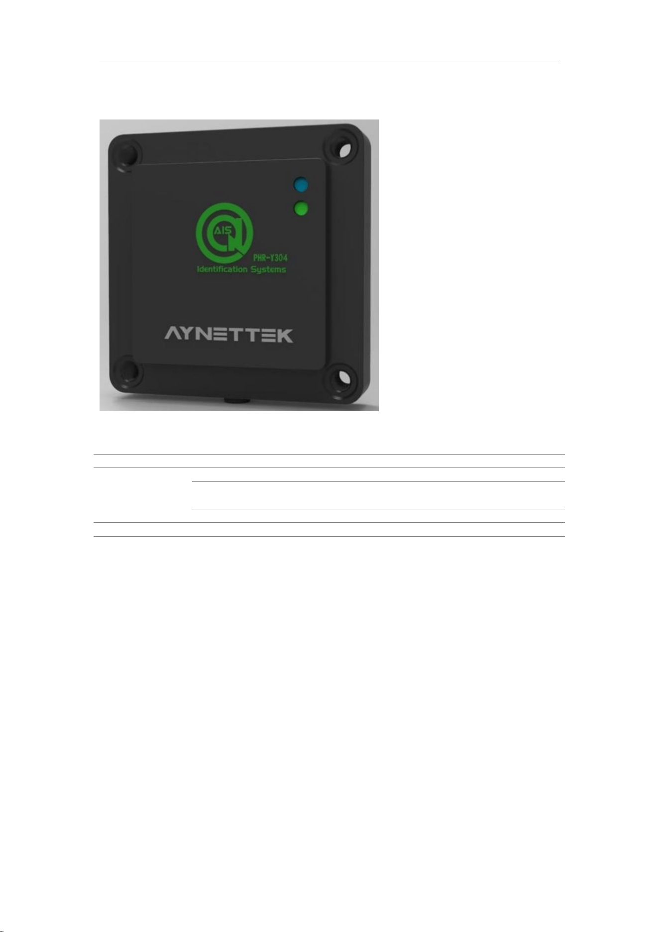
The Anet high-frequency series readers are a series of general-purpose high-frequency
RFID readers suitable for various industrial applications. This series includes both integrated
and separate types of RFID reader products, as well as supporting antennas, tags, cables, and
other products. Products of various sizes can be combined and matched to suit various
applications in industries such as 3C, home appliances, automotive, new energy, and
equipment.
The functions of the reader can be specifically divided into two main categories:
Tag Read/Write Operations
General I/O Control
Tag Read/Write Operations
The Anet high-frequency series products support ISO-15963 and ISO-14443A
protocols, enabling read and write operations on electronic tags compliant with these
protocols.
General I/O
Some products in the Anet high-frequency series feature two isolated adaptive GPIO
interfaces. These can receive and output I/O signals (such as controlling switches,
photoelectric sensors, alarms, etc.) through the general I/O functionality.
The main features of the high-frequency series readers are as follows:
Operating frequency of 13.56MHz, compliant with ISO-15693 and ISO-14443A
standards;
Supports RS-485 (Modbus RTU) and POE (Modbus TCP) communication methods,
facilitating large-scale networking applications for enterprises;
Industrial standard EMC design effectively resists various interferences in industrial
environments;
Compact structural design for easy installation;
IP67 protection suitable for various installation environments.
High-Frequency Series Products User Manual Anet Intelligent Technology
7
2. HardwareInterfaceDescription
Reader port introduction
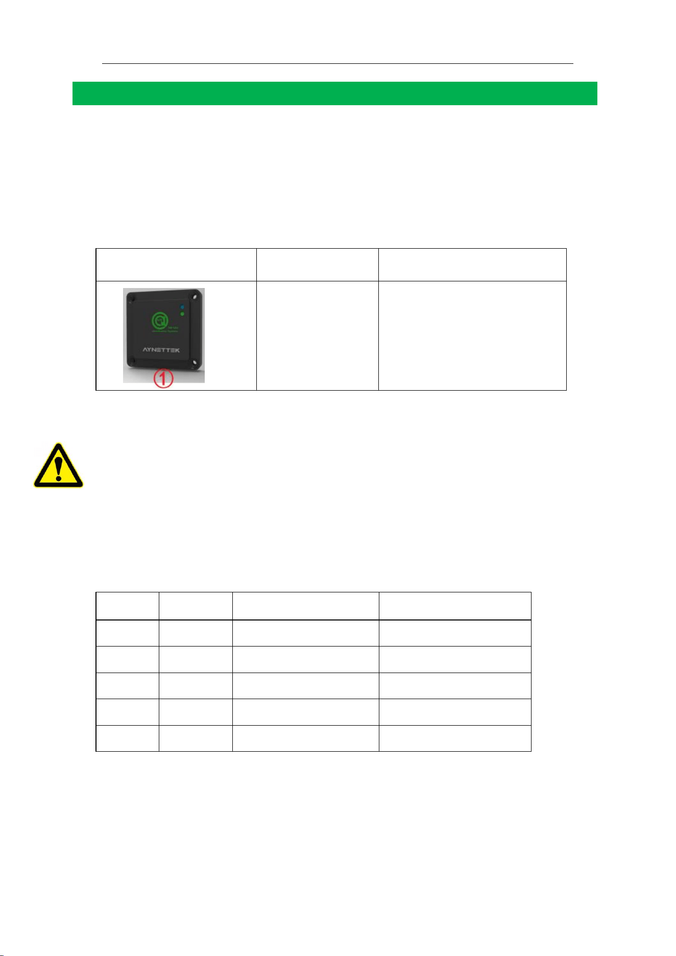
Anait high-frequency series readers have four types of external interfaces: antenna
connection interface, GPIO interface, POE interface, and 485 & power interface. Each
interface connects to the corresponding external device through a customized cable. The
following table provides the interface descriptions for the entire series of products.
Table1
High-frequency P series reader interface model
Product image
Product model
Port Type
AIS-PHR-Y304
AIS-PHR-Y305
①5-core shielded loose wire 485
& power port (length can be
customized)
ReaderInterface Pin Definition
Definition of external connection wire M12 terminals. When connecting to loose wire
cables, please strictly follow the terminal definition table below. If our company provides
If you have standard injection-molded cable products, please prioritize purchasing our
finished cables. It is not recommended to assemble cables on your own. If the cable length is
insufficient, you can use an extension cord or consult with our company to customize the
cable.
Table2 485 & Power Interface Terminal Definition Table with Built-in Tail Wire
Serial
Number
Definition
Reader
Tail line scattered line
1
24V+
1
Red
2
24-
2
Green
3
RS485_A
3
White
4
RS485_B
4
Black
5
NC
5
Huang
High-Frequency Series Products User Manual Anet Intelligent Technology
8
Reader Working Indicator Definition
Table3 Blue-Green Dual Indicator Model Definition
Number
Description
Green
Always on, power supply is normal
Off, there is a tag in the reading area, at this time the blue light is
always on
Flashing, data interaction with the reader
Blue
Changliang, there are tags in the reading area

High-Frequency Series Products User Manual Anet Intelligent Technology
9
3. Reader General SpecificationsParameters
Electrical Parameters
Table4 Reader Electrical Parameters
Name
Parameters
Wireless Protocol
IS0-15693 (ISO-14443A optional)
Operating
Frequency
13.56MHz
Supported Areas
SRRC China, FCC North America, ETSI Europe
Output Power
Related to Model
Wireless Rate
26.5kbit/S
Reading Distance
Related to Model
Communication
Interface
RS-485 or TCP
Serial
Communication Rate
115.2kbit/s (configurable)
Ethernet
communication rate
10/100M adaptive
Power supply
voltage
DC 24V+/-10% (RS-485), DC 48V+/-10% (POE)
Average current
Related to Model
Application environment parameters
Table5 Reader position and interface function definition
Operating
temperature
-40℃ to +70℃
Storage
Temperature
-40℃~+85℃
Operating
Humidity
5%~95%RH (non-condensing)
Water and
Dust Resistance
Rating
IP67
Drop Test
GB/T2423.8-1995
Appearance Parameters
Please refer to the technical specifications of the corresponding model.
High-Frequency Series Products User Manual Anet Intelligent Technology
10
4. DEMO test environment setup
DEMO Hardware Environment Setup
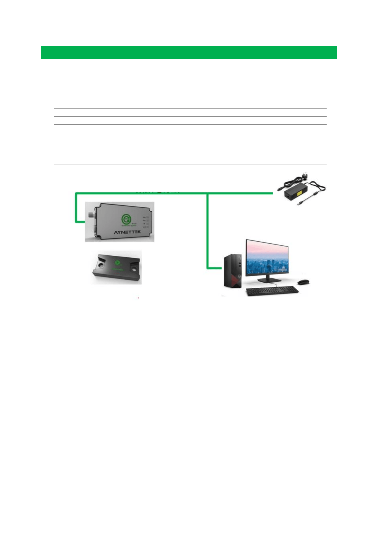
Table6 Hardware Required for DEMO Environment Setup
Reader
RS485 Model
Power Supply
Equipment
24V Adapter or DC Power Supply (with terminals)
Data Cable
RS485 to USB Data Cable (with terminals)
Data Power Cable
RS485 Data Power Cable (provided by our company)
Reader Antenna
(Optional)
Split-Type Model Optional
Label
Selection Label
Network Cable
Standard Network Cable
Computer
Windows System Computer
RS485 Model Wiring Definition
High-Frequency Series Products User Manual Anet Intelligent Technology
11
DEMO Software Environment Setup
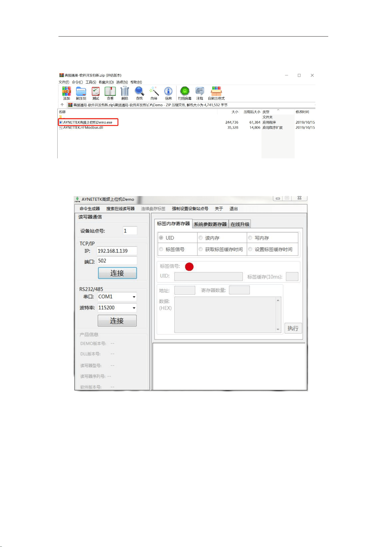
Select the DEMO executable provided in our development package and double-click to run.
For the POE model, select TCP/IP connection, and the default IP port is shown in the figure
below. For the RS485 model, select serial connection, with a default baud rate of 115200.
For detailed usage of the DEMO software, please refer to the "High-Frequency Reader
DEMO User Reference Manual" in the software development package.
High-Frequency Series Products User Manual Anet Intelligent Technology
12
5. Installation Precautions
Bracket Design
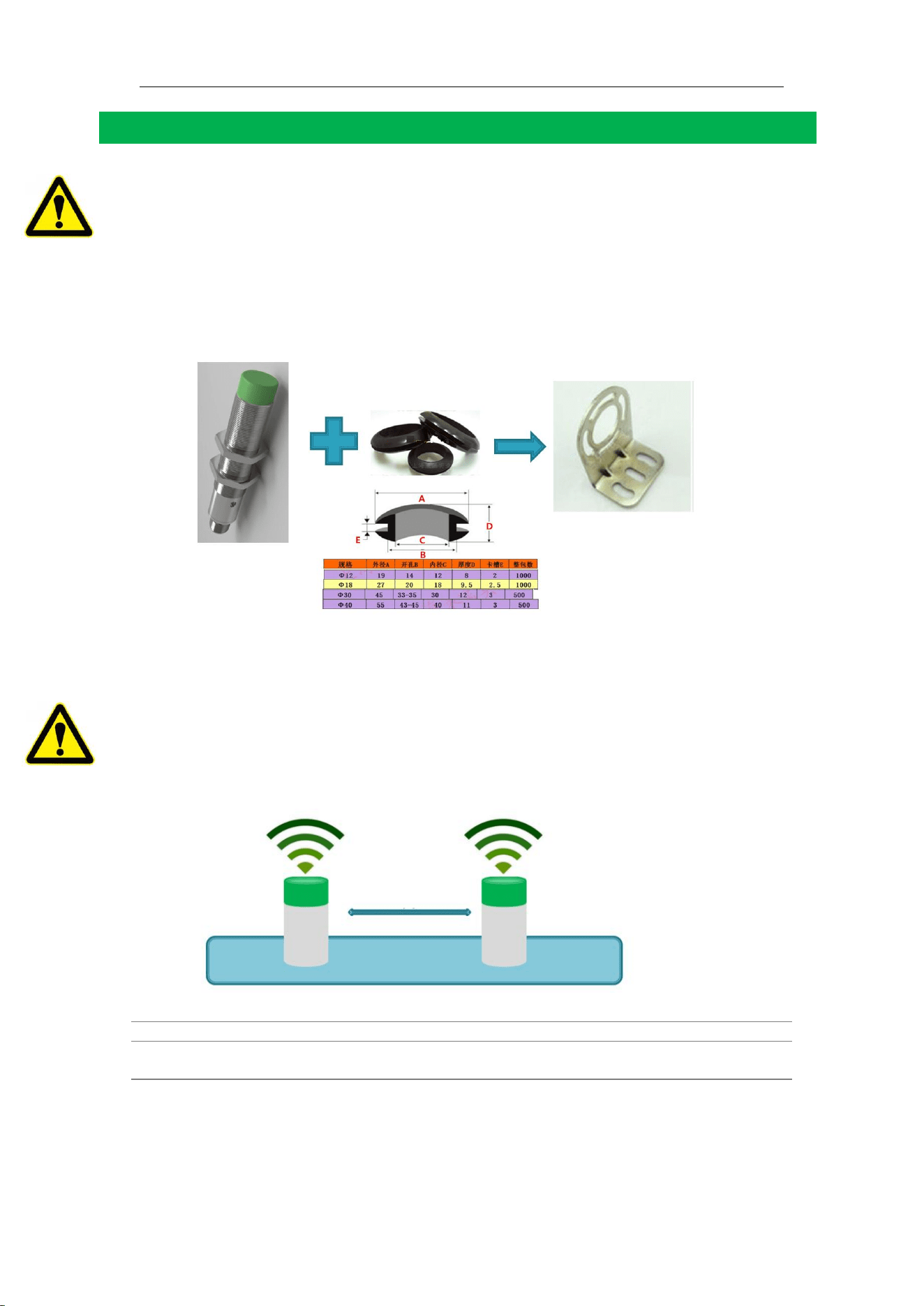
!!!!The reader's antenna cover is made of non-metallic material; impact is prohibited!!!!
The high-frequency reader is sensitive to low-frequency interference signals, requiring the
device casing to be well grounded to shield external interference. However, production line
equipment has various motors and is difficult to ground properly. If the reader's metal casing
is directly connected to the equipment, it may conduct interference signals from the
equipment. Therefore, when designing the bracket, insulating materials should be used to
isolate the reader (including the antenna) metal casing from the mechanical equipment.
Insulating materials such as PC and bakelite can be used. We also provide corresponding
installation components to facilitate the bracket's insulation design.
Cylindrical readers or antennas should be used with rubber rings.
Reader Installation Spacing
The high-frequency reader reads and writes tags through the magnetic field around the
antenna. If two devices are installed too close to each other, their antenna radiation
magnetic fields will interfere with each other's ability to read tags. Therefore, the installation
distance of all readers or antennas should follow the distances in the table below. If it cannot
be avoided on-site, the readers need to operate in a time-sharing polling mode.
Table7 Reader Installation Spacing Table
Reader Model
Installation Safety Distance (cm)
AIS-PHR-Y304
AIS-PHR-Y305
40cm
Note: The spacing for split-type readers depends on the size of their connected antennas,
referring to the spacing of readers with antennas of the same size. The antennas connected
to the same split-type device do not interfere with each other.
High-Frequency Series Products User Manual Anet Intelligent Technology
13
Reader Data Power Line Placement
High-frequency readers read and write tags through the magnetic field around the antenna.
The production equipment's motor generates electromagnetic components, which, if
significant, may affect the normal operation of the reader. This is especially true when the
reader's power data line is laid flat alongside the equipment's power line, particularly if it is
long. Therefore, it is recommended:
The reader's power data line should be routed in a separate cable tray;
The feed line of the split-type antenna should not be coiled or placed in a spiral
manner.
Selection of Reading and Writing Distance
The high-frequency reader writes and reads tags through the magnetic field around the
antenna. The electromagnetic components around the reader can interfere with its normal
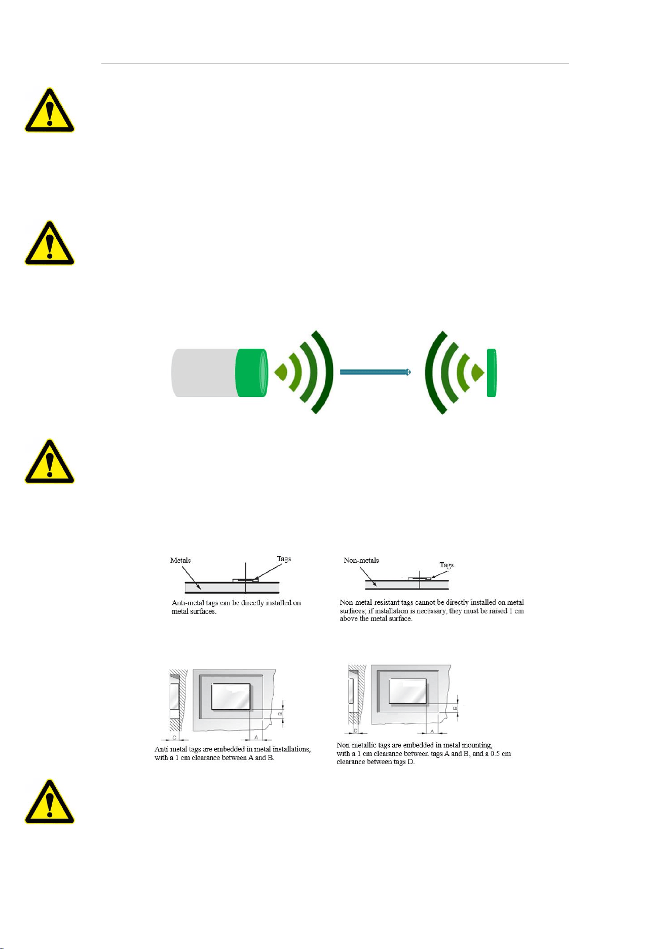
operation. Therefore, it is recommended to use 60% of the maximum reading distance of the
reader as the installation distance. Additionally, the reader's antenna should be aligned with
the tag's antenna.
Installation of the tag
High-frequency tags also communicate with the reader through a magnetic field. When the
magnetic field encounters metal, it generates a reverse eddy current magnetic field due to
Lenz's law, which cancels out the magnetic field produced by the reader, causing a sharp
decline in the magnetic field energy received by the tag, making it unreadable. To mitigate
the impact of metal, magnetic materials need to be added to the bottom of the tag, or a
clearance area should be reserved during installation.
Estimation of maximum speed of tag movement
The maximum speed allowed for mobile reading. If reading while in motion, the readable
range at the current reading distance needs to be measured, and based on the number of
bytes read, the time required for two readings should be estimated. Speed = readable range
/ time required.

FCC Warning
This device complies with part 15 of the FCC rules. Operation is subject to the following two
conditions: (1) this device may not cause harmful interference, and (2) this device must accept
any inte rference received, including interference that may cause undesired operation.
Changes or modifications not expressly approved by the party responsible for compliance could
void the user's authority to operate the equipment.
NOTE: This equipment has been tested and found to comply with the limits for a Class B digital
device, pursuant to part 15 of the FCC Rules. These limits are designed to provide reasonable
protection against harmful interference in a residential installation. This equipment generates
uses and can radiate radio frequency energy and, if not installed and used in accordance with the
instructions, may cause harmful interference to radio communications. However, there is no
guarantee that interference will not occur in a particular installation. If this equipment does
cause harmful interferenceto radio or television reception, which can be determined by turning
the equipment off and on, the user is encouraged to try to correct the interference by one or
more of the following measures:
• Reorient or relocate the receiving antenna.
• Increase the separation between the equipment and receiver.
• Connect the equipment into an outlet on a circuit different from that to which the receiver is
connected.
• Consult the dealer or an experienced radio/TV technician for help.
Radiation Exposure Statement
This equipment complies with FCC radiation exposure limits set forth for an uncontrolled
environment. This equipment should be installed and operated with minimum distance 20cm
between the radiator and your body.