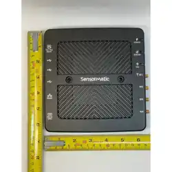
IDX-5000 Multipurpose RFID Reader POS Quick Start Guide
© 2026 Johnson Controls. All rights reserved.
*8200-2697-74*
2026-06-19
8200-2697-74
Rev C
IDX-5000
About this guide
This guide describes how to connect and mount the IDX-5000 Multipurpose RFID Reader. To install the IDX-5000 Multipurpose RFID
Reader as part of a solution, refer to the following guides:
• IDX-5000 Multipurpose RFID Reader Installation Guide, 8200-2697-79
• IDX-5000 Multipurpose RFID Reader Information Sheet, 8200-2697-78
Technical support
For product bulletins and updates to documentation, if you are a Johnson Controls employee or Johnson Controls subcontractor, visit
http://sensormatictechsupport.jci.com. If you are a business partner, visit http://www.globalpartneredge.com.
QR code
To access the IDX-5000 Multipurpose RFID Reader POS Installation Guide, scan the QR code.
Figure 1: QR code
Document link: https://docs.jci.com/sensormatic/IDX-5000-IG
About the product
The IDX-5000 Multipurpose RFID reader kit includes contents for the following part numbers:
• IDX5-N: For use in the US, Canada, and other countries that follow US regulations exactly. This kit includes a universal power
supply with a US power cord and a USB cable.
• IDX5-E: For use in the EU. This kit includes a USB cable and a universal power supply. Order a power cord separately.
• IDX5-W: This kit includes a USB cable and a universal power supply. Order a power cord separately.
Connecting an antenna to the reader
1. Use a screw-on RP-SMA connector to connect the antenna cable to an available RF output port.
2. To secure the connection, tighten the SMA connector using an SMA torque wrench to 1 N·m or 8.85 lb-in. A loose connection can
compromise the performance of the reader.
Important: To avoid permanent damage to the reader and cable, do not over-tighten the SMA connector.
Figure 2: RF connectors and power input connectors on the reader
Callout Component Callout Component
A Port 4 status LED G Port 1 status LED
B RF Port 4 H RF Port 1
C Port 3 status LED I Tag LED
D RF Port 3 J Status LED
E Port 2 status LED K Power LED
F RF Port 2
Digital connections
For information on the connections on the IDX-5000 Multipurpose RFID Reader, see Figure 3.
Figure 3: Digital end panel connectors
Callout Component Description
A Configuration
access switch
To restore the reader to a factory default configuration file, use a thin object such as a straightened
paper clip to press the recessed configuration access switch.
Press and hold the switch for 10 seconds until the Status LED turns green, and then release the
switch. Within 10 seconds, press and release the switch again to confirm the update. The LED turns
off, the default settings load, and the reader reboots.
B Ethernet +
PoE/48VDC
10/100/1000 Mbit Ethernet + PoE, or 48 VDC only for non-Ethernet installs
• Full power Sensormatic power supplies: 25 W 802.3at PoE supply and 48 V, 30 W brick supply (for
non-Ethernet installs)
• Reduced power, reduced capability (customer provided): 13 W 802.3af PoE supply
C and D USB A host port The USB host ports support USB devices such as flash drives
E USB B device port The port implements Ethernet over USB using the USB NCM interface, supported by later versions of
Microsoft® Windows®, and Linux®
F RS-485 port RS-485 port for connection to Sensormatic RS-485 devices
G GPIO/RS-232 port This port allows the reader to control LEDs, buzzers, receive input from switches and to communicate
using RS-232. Details are provided by Sensormatic separately.
Powering the reader
An Ethernet-connected reader is powered by either a PoE-equipped Ethernet switch or a Sensormatic PoE-Midspan supply. A USB-only
reader is powered with the Sensormatic 48VDC RJ45 supply.
Access for configuration
The IDX-5000 only supports firmware upgrades and remote setup using the Sensormatic Device Manager over an internet connection.
Coordinate with the Sensormatic Professional Services team to configure the IDX-5000 when it is online.
LED definitions
For information on the IDX-5000 Multipurpose RFID Reader LEDs, see Table 1. For the location of the LEDs on the reader, see Figure 2.
Table 1: Reader LED definitions
LED LED state Description
Solid green The power is on and the unit is ready to use.
Off There is no power to the unit.
Power
Solid amber The unit is powering on.
Off The reader is operational, and is not under LLRP management.
Solid amber The unit is powering on.
Blinking amber Software is downloading to the reader.
Solid green Normal run mode
Status
Solid red The reader is detecting an error or self-test has failed.
Flashing green The reader is reading a valid tag.
Flashing amber The reader reads a tag but is discarding it because the Received Signal Strength Indication (RSSI) is
below the programmed threshold.
Tag
Flashing red Set the country of operation. The reader does not emit RF or read tags until this is set.
Amber The transmitter is active.
Off The transmitter is not active.
Three amber blinks The reader has established communication with a 1-Wire® device.
RF Status
Two amber blinks The reader has lost communication with a 1-Wire device.
Mounting the reader
CAUTION
Observe the minimum bend radius specified for the associated antenna cable when the cable must change
direction. A crushed or kinked antenna cable impairs reader performance.
1. Locate an area to mount the reader, and position the reader on the surface.
Note: An ideal mounting surface continuously conducts heat away from the reader case.
2. Ensure that there is a minimum of 10 cm (4 in.) of clearance around all exposed reader surfaces for ventilation.
3. Mark the mounting holes on the surface. At the marked locations, drill two mounting holes.
4. Position the reader over the mounting holes, and secure the reader using self-tapping screws, 5810-5091-120.
Note: The IDX-5000 RFID reader kit contains two screws. If these screws are unsuitable for your mounting scenario,
source alternative screws.
Figure 4: Mounting hole dimensions, mm
Callout Component
A M4 or #10 pan head Phillips screw
Specifications
Table 2: Specifications
Specification Value
Device electrical input POE 802.3 30 W or Sensormatic DC Supply
Device electrical output RF connector for approved antennas only, GPIO Ports
DC Power supply input Max 100-240V 50/60 Hz 1.8A, IEC 320 3-Pin C14
DC Power supply output DC 48V/620 mA
Product dimensions 16.4 cm (6.45 in.) x 16.5 cm (6.5 in.) x 2.7cm (1.1 in.)
Product weight 0.86 kg (1.9 lbs.)
Packaged dimensions 27.3 cm (10.75 in.) x 23.8 cm (9.38 in.) x 7.14 cm (2.81 in.)
Packaged weight 1.6 kg (3.5 lbs)
Power supply
Use only the power supplies and cords listed in Table 3.
Table 3: Power cord numbers
Part number Description Power cords
2025-0653-01 PoE Midspan Supply, 802.3 at, 30 W, 1 port (for Ethernet applications) No
5606-0155-01 Power supply, 48 V, 30 W, RJ45 (for USB-only applications) No
0351-0547-01 NA: 125 V, US, 1-15/C7, 2 m (6 ft) Yes
0351-0547-02 EU:250 V, CEE7/16-C7, ungrounded Euro plug, 2 m (6 ft) Yes
0351-0547-03 UK:250 V, BS1363-C7, ungrounded UK plug, 2 m (6 ft) Yes
0351-0547-04 Japan:125 V, 2.5 A, Japan-IEC, 2 m (6 ft) Yes
0351-0547-07 Australia:250 V, AS3112-C7, 2 m (6 ft) Yes
0351-0547-09 China:250 V, 2.5 A, China-IEC, 2 m (6 ft) Yes
Environmental
• Operating temperature: 0°C to 50°C (32°F to 122°F)
• Storage temperature: -20°C to 85 °C (-4°F to 185°F)
• Relative humidity: 5% to 95%, non-condensing
• Use: This product is designed for commercial and industrial indoor use only.
Regulatory information
Declaration of conformity to EU Directives and GB Regulations
EU: Sensormatic USA LLC declares that this product is in compliance with Directive 2014/53/EU on radio equipment and Directive
2011/65/EU on the reduction of hazardous substances.
GB: Sensormatic USA LLC declares that this product is in compliance with the UK Radio Equipment Regulations 2017 and The Restriction
of the Use of Certain Hazardous Substances in Electrical and Electronic Equipment Regulations 2012.
To access the EU and UK declaration of conformity, click on the following link: https://docs.jci.com/Sensormatic/Declaration-of-
Conformity
Battery content
This product contains a non-rechargeable coin cell battery:
CR 2032 Lithium Coin Cell
Nominal Voltage: 3V
Nominal Capacity: 240 mAh
Net Weight: 2.9 g
Lithium Content: 0.065 g
Chemistry: Li/MnO2
Approved antennas
Table 4 lists the antennas that are approved for use with the IDX-5000 Multipurpose RFID Reader.
Table 4: Approved antennas
Manufacturer Part number Type Gain (dBi) Cable loss
Sensormatic IDA-1000 Patch 4.5 N/A *
Sensormatic IDA-3100 Patch 6 N/A *
Sensormatic IDA-3300 Patch 7.21 N/A *
Sensormatic IKDM-10XX Patch -8 3.5
Sensormatic IDSM-1000/ IDSM-1100 Patch 6 N/A *
Keonn Advantenna-CP11™ Patch 0.2 1.5
Keonn Advantenna-p11™ Patch 3.6 1.5
Keonn ADVANTENNA-P12 Patch 3.5 1.5
Keonn Advantenna-SP11™ Patch 4.8 1.5
NeWave NSSWave-N5 Patch 4.5 1.5
Sensormatic UHIDX1901 Patch 6 N/A *
*The cable is permanently attached to this antenna.
The IDKM-1000 and the IDKM-1010 antennas are not approved for use in the following countries:
• Algeria
• Kuwait
• Costa Rica
• Egypt
• Chile
• Lebanon
• United Arab Emirates
The IDA-3100, IDSM-1000, and IDSM-1100 antennas are not approved for use in Russia and South Korea.
The following countries are restricted to low power:
• Ecuador
• Morocco
• Honduras
• Uruguay
Note: Refer to IDX-5000 Multipurpose RFID Reader Information Sheet, 8200-2697-78 for a full list of countries that can use any of
the approved antennas listed in Table 4.
ISED ID: 3506A-IDX5000, MODEL: UHID2201
This device contains licence-exempt transmitter(s)/receiver(s) that comply with Innovation, Science and Economic Development
Canada's licence-exempt RSS(s). Operation is subject to the following two conditions:
1. This device may not cause interference.
2. This device must accept any interference, including interference that may cause undesired operation of the device.
This device complies with the Canadian ICES-003 Class B specifications. CAN ICES-003(B) / NMB-003(B).
L’émetteur/récepteur exempt de licence contenu dans le présent appareil est conforme aux CNR d’Innovation, Sciences et
Développement économique Canada applicables aux appareils radio exempt de licence. L’exploitation est autorisée aux deux
conditions suivantes:
1. L’appareil ne doit pas produire de brouillage.
2. L’appareil doit accepter tout brouillage radioélectrique subi, même si le brouillage est susceptible d’en compromettre le
fonctionnement.
Cet appareil numérique de la classe B est conforme à la norme NMB-003 du Canada.
This radio transmitter 3506A-IDX5000 has been approved by Innovation, Science and Economic Development Canada to operate with
the antenna types listed in Table 4, with the maximum permissible gain indicated. Antenna types not included in this list that have a
gain greater than the maximum gain indicated for any type listed are strictly prohibited for use with this device.
Le présent émetteur radio 3506A-IDX5000 a été approuvé par Innovation, Sciences et Développement économique Canada pour
fonctionner avec les types d'antenne Listé dans Tableau 4 et ayant un gain admissible maximal. Les types d'antenne non inclus dans
cette liste, et dont le gain est supérieur au gain maximal indiqué pour tout type figurant sur la liste, sont strictement interdits pour
l'exploitation de l'émetteur.
Under Innovation, Science and Economic Development regulations, this radio transmitter may only operate using an antenna of a
type and maximum (or lesser) gain approved for the transmitter by ISED. To reduce potential radio interference to other users, the
antenna type and its gain should be so chosen that the equivalent isotropically radiated power (EIRP) is not more than that necessary
for successful communication.
Conformément à la réglementation d'Innovation, Sciences et Développement économique Canada, le présent émetteur radio peut
fonctionner avec une antenne d'un type et d'un gain maximal (ou inférieur) approuvé pour l'émetteur par Innovation, Sciences
et Développement économique Canada. Dans le but de réduire les risques de brouillage radioélectrique à l'intention des autres
utilisateurs, il faut choisir le type d'antenne et son gain de sorte que la puissance isotrope rayonnée équivalente (PIRE) ne dépasse pas
l'intensité nécessaire à l'établissement d'une communication satisfaisante.
Antenna installation
This equipment complies with ISED RSS-102 radiation exposure limits set forth for an uncontrolled environment. This equipment should
be installed and operated with minimum distance 34 cm (13.4 inches) between the radiator and any part of your body. This transmitter
must not be co-located or operating in conjunction with any other antenna or transmitter. Cet équipement est conforme aux limites
d’exposition aux radiations ISED CNR-102 établies pour un environnement non contrôlé. Une distance de séparation d'au moins 34 cm
doivent être maintenue entre l'antenne de cet appareil et toutes les personnes. Lanceurs ou ne peuvent pas coexister cette antenne ou
capteurs avec d’autres.
FCCID: BVCIDX5000
Regulatory Model: UHIDX2201
This device complies with part 15 of the FCC Rules. Operation is subject to the following two conditions:
• This device may not cause harmful interference
• This device must accept any interference received, including interference that may cause undesired operation.
Note: This equipment has been tested and found to comply with the limits for a Class B digital device, pursuant to part 15
of the FCC Rules. These limits are designed to provide reasonable protection against harmful interference in a residential
installation. This equipment generates, uses and can radiate radio frequency energy and, if not installed and used in
accordance with the instructions, may cause harmful interference to radio communications. However, there is no guarantee
that interference will not occur in a particular installation. If this equipment does cause harmful interference to radio or
television reception, which can be determined by turning the equipment off and on, the user is encouraged to try to correct
the interference by one or more of the following measures: reorient or relocate the receiving antenna, increase the separation
between the equipment and receiver, connect the equipment into an outlet on a circuit different from that to which the
receiver is connected, and/or consult the dealer or an experienced radio/TV technician for help.
This equipment complies with FCC radiation exposure limits set forth for an uncontrolled environment. This transmitter must not be
co-located or operating in conjunction with any other antenna or transmitter. In order to avoid the possibility of exceeding the FCC
radio frequency exposure limits, this equipment should be installed and operated with minimum distance 23 cm (9.1 inches) between
the antenna and your body during normal operation. Users must follow the specific operating instructions for satisfying RF exposure
compliance.
For the State of California, U.S.A. only: Perchlorate Material - Special Handling May Apply. See http://www.dtsc.ca.gov/
hazardouswaste/perchlorate.This product includes a real-time clock battery or coin cell battery that may contain perchlorate and may
require special handling when recycled or disposed of in California.
MéxicoNOM 121: UHIDX2201
La operación de este equipo está sujeta a las siguientes dos condiciones:
• Es posible que este equipo o dispositivo no cause interferencia perjudicial y
• Este equipo debe aceptar cualquier interferencia, incluyendo la que pueda causar su propia operación no deseada.
47 CFR, Part 15
ICES-003
RSS-210
NOM 121
EN302 208
EMC
EN301 489
Safety UL/CSA/EN 62368-1
Equipment Modification Caution
Equipment changes or modifications not expressly approved by Sensormatic Electronics, LLC, the party responsible for FCC compliance,
could void the user’s authority to operate the equipment and could create a hazardous condition.
Installation: Installation must be performed by a Sensormatic authorised install or service agent.
Service and repair: Servicing and repair must be performed by a Sensormatic authorised service or repair agent. This product has no
user-repairable parts.
Restriction of Hazardous Substances Directive (RoHS)
All parts and components are manufactured in accordance to and to be compliant with the DIRECTIVE 2002/95/EC OF THE EUROPEAN
PARLIAMENT AND OF THE COUNCIL of 27 January 2003 on the restriction of the use of certain hazardous substances in electrical and electronic
equipment.
WEEE directive
This label indicates that this product should not be disposed of with household waste. It should be deposited at an appropriate facility
to enable recovery and recycling. For information on how to recycle this product, contact your sales or technical support contact.
Service
If a problem occurs while using the equipment, contact the facility Technical or Systems Support. If there is a problem with the
equipment, contact Sensormatic Technical Support at http://sensormaticsecurelogin.com.
Sensormatic USA, LLC makes no representation or warranty with respect to the contents hereof and specifically disclaims any implied
warranties of merchantability or fitness for any particular purpose. Further, Sensormatic USA, LLC reserves the right to revise this
publication and make changes from time to time in the content hereof without obligation of Sensormatic USA, LLC to notify any person
of such revision or changes.
Sensormatic and the Sensormatic logo are registered trademarks of Sensormatic USA, LLC. 1-Wire is a registered trademark of Maxim
Integrated Products. All other product names or company names mentioned in this document may be trademarks or registered
trademarks of their respective companies and are hereby acknowledged.
For EU customers: All products at the end of their life must be returned to Sensormatic for recycling. For information on how to return
the product, visit: http://sensormatic.com/WhoWeAre/Eco-Initiatives.aspx.
© 2026 Johnson Controls. All rights reserved.

