
EDGE-
35
Hardware
Install
Guide
PLT-07365,
A.3
2
April 2026
Public
EDGE-35R
Hardware
Install
Guide

EDGE-
35
Hardware
Install
Guide
PLT-07365,
A.3
3
April 2026
Public
PLT-0736 A.3ctober 2023
Copyright
© 2025 Acura/HID Global Corporation/ASSA ABLOY AB. All rights reserved.
This document may not be reproduced, disseminated, or republished in any form without the prior written permission of
HID Global Corporation.
Trademarks
Acura is a trademark or registered trademark of HID Global, ASSA ABLOY AB, or its affiliate(s) in the US and other
countries and may not be used without permission. All other trademarks, service marks, and product or service names
are trademarks or registered trademarks of their respective owners.
Contacts
For technical support, please contact: acura.support@hidglobal.com.

EDGE-
35
Hardware
Install
Guide
PLT-07365,
A.3
4
April 2026
Public
Introduction _____________________________________________________________________________
4
1.1
Introduction __________________________________________________________________________________________ 5
1.2
Products covered by this document _____________________________________________________________________ 5
1.3
Approval notes _______________________________________________________________________________________ 5
1.3.1
Anatel (Brazil) ___________________________________________________________________________________ 5
FCC (USA) 5
1.3.2
Authorized antenna ______________________________________________________________________________ 7
Specifications ___________________________________________________________________________
8
2.1
EDGE-35 unit ________________________________________________________________________________________ 9
2.1.1
Dimensions ____________________________________________________________________________________ 10
2.1.2
Specification (EDGE-35) _________________________________________________________________________ 11
2.2
Hardware interface board ____________________________________________________________________________ 13
2.2.1
Dimensions ____________________________________________________________________________________ 14
2.2.2
Specification (hardware interface board) ___________________________________________________________ 15
Installation _____________________________________________________________________________
16
3.1
Mounting kit components ____________________________________________________________________________ 17
3.1.1
Mounting kit assembly __________________________________________________________________________ 18
3.1.2
Mounting the EDGE-35 _________________________________________________________________________ 19
3.1.3
Mounting kit operational angles __________________________________________________________________ 19
3.1.4
Unused connector cover ________________________________________________________________________ 20
3.1.5
RJ45 Cable plug jacket __________________________________________________________________________ 20
3.2
EDGE-35 recommended installation positions ___________________________________________________________ 22
3.2.1
EDGE-35 located at the side of the lane ____________________________________________________________ 22
3.2.2
EDGE-35 located in the center of the lane __________________________________________________________ 23
3.3
Troubleshooting - tag reading _________________________________________________________________________ 24
3.4
Reader operation - visual feedback_____________________________________________________________________ 25
3.5
Installation check list ________________________________________________________________________________ 26
Electrical _______________________________________________________________________________
27
4.1
Connection diagram _________________________________________________________________________________ 28
4.2
Port pinout _________________________________________________________________________________________ 29
4.2.1
POE port pinout ________________________________________________________________________________ 29
4.2.2
SIG port pinout _________________________________________________________________________________ 30
4.3
Interface board connections __________________________________________________________________________ 31
4.3.1
Wiegand/Abatrack/RS-232_______________________________________________________________________ 31
4.3.2
Digital input (sensors) ___________________________________________________________________________ 31
4.3.3
Output (Relay) _________________________________________________________________________________ 31

Public
Section
01
Introduction
Public
authority to operate this equipment.
This transmitter must not be co-located or operating in conjunction with any
other antenna or transmitter.
Warning:
1.1
Introduction
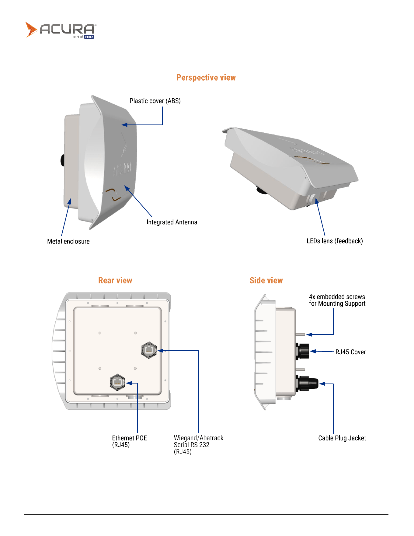
The EDGE-35 is a compact Ultra High Frequency (UHF) RFID reader that offers high-performance tag reading.
The
reader has a range of features and functionalities that are ideal for vehicle identification, including:
⚫
Ethernet TCP/IP communication for seamless connectivity.
⚫
Isolated serial interface, Wiegand/Clock-and-Data (Abatrack II) or RS-232.
⚫
Outdoor installation.
⚫
Easy configuration through the user-friendly HTML page interface.
⚫
Integrated antenna with 7,5 dBic gain eliminates the need for RF cables.
⚫
Powered via Power over Ethernet (PoE) via POE Switch or POE injector.
⚫
Compact size that does not compromise the aesthetic appeal of the installation site.
⚫
Easy to use, has automatic tag reading, does not require software development using API/SDK.
1.2
Products covered by this document
Model
Code
EDGE-35
R TCP/IP
Please
contact
us.
EDGE-35
R TCP/IP WIFI
Please
contact
us
INTERFACE
BOARD
EDGE-35
100.699
1.3
Approval notes
1.3.1
Anatel (Brazil)
EDGE-35 was tested and approved under the Regulation for Certification and Homologation of telecommunications Products,
approved by Anatel Resolution No. 242 of November 30, 2000.
⚫
Types: Radio Frequency Identification Systems - Category II.
⚫
Service/Application:
Restricted
Radiation
Radiocommunication.
1.3.2
FCC (USA)
Federal Communication Commission Interference Statement (FCC):
This device complies with Part 15 of the FCC Rules. Operation is subject to the following two conditions: (1) This device may
not cause harmful interference, and (2) this device must accept any interference received, including interference that may
cause undesired operation.
NOTE: This equipment has been tested and found to comply with the limits for a Class A digital device, pursuant to part 15 of
the FCC Rules. These limits are designed to provide reasonable protection against harmful interference when the equipment
is operating in commercial environment. This equipment generates, uses, and can radiate radiofrequency energy and, if not
installed and used in accordance with the instruction manual, may cause harmful interference to radio communications.
Operation of this equipment in a residential area is likely to cause harmful interference in which case the user will be required
to correct the interference at his own expense.
Public
1.3.3
Authorized antenna
Vendor
Acura
Model
Far
Field
PCB
150122
(Embedded
antenna)
Frequency
Range
(MHz)
902-928
MHz
Antenna Gain
(dBi)
6
dBi
Polarization
Circular
(RHCP)
Type
Patch

Public
Section
02
Specifications
Public
2.1
EDGE-35 unit
Public
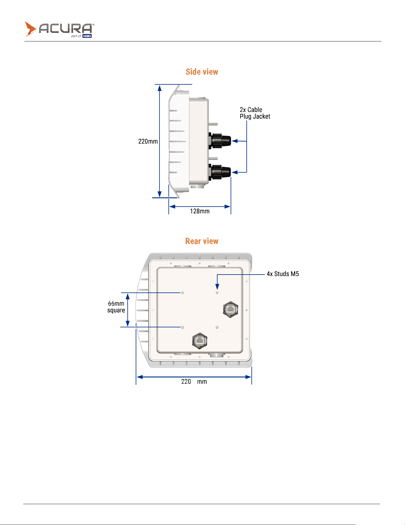
2.1.1
Dimensions
Public
2.1.2
Specification (EDGE-35)
Transponder Protocol
Protocol
ISO
18000-6C
(EPC
Gen2)
Interface RF
RF
Output
power
From
0
to
30
dBm
with
0.5
dBm
increment
Regulation
ANATEL (Brazil) 902 – 907MHz and 915 – 928MHz
FCC (USA) 902 – 928MHz
Mode
Frequency
Hopping
Modulation/RF
Coding
PR-ASK
/
Miller4
(M4)
Backscatter Link Frequency
(BLF)
250KHz
Performance
Reading distance (the reading
distance can vary depending on
the tag model, usage mode,
and environment)
6
meters
Data/Control Interface
POE
connector:
⚫
Ethernet
10/100
Mbps
(1.5KV
RMS
insulation)
⚫
POE
(IEEE
802.3af
standard)
⚫
POE
modes
supported:
-
Mode
A
(mixed
DC
&
data)
-
Mode
B
(DC
on
spares)
SIG
connector:
⚫
1x
Optically
isolated
Digital
Input:
-
1KV
RMS
insulation.
-
Supports
Dry
Contact,
NPN
(Sinking),
and
PNP
circuit
(Sourcing).
Minimum
pulse
width:
100ms.
-
High
Level
(3.0
to
24.0
VDC),
Low
Level
(0
to
2.0
VDC).
⚫
1x
optically
isolated
Digital
Output:
-
1KV
RMS
insulation.
-
Controlled
by
tag
reading
or/and
ASCII
commands.
-
High
Level
(5.0
VDC),
Low
Level
(0
VDC)
Programming
Does not require software development using API/SDK. With a simple Socket connection, the tag read
results can be processed.

Public
Energy
Power
IEEE 802.3af Powered Device (PD)
PD Power Class: Class 3, 12.95W
Operating
PoE
Voltage:
37VDC
to
57VDC
Consumption
Max.
15W.
With
maximum
power
and
high
duty
cycle
Physical characteristics
IP
rating
IP65
(RJ45
ingress
protection
cover
and
cable
plug
jacket
included)
Integrated
antenna
Patch
circular
polarized
antenna
with
7.5
dBic
of
gain
(RHCP)
Dimensions
220
x
220
x
128
mm
(HxWxD)
with
Cable
Plug
Jacket
Weight
1.4Kg
(3.08lb)
Operation
temperature
-10ºC
to
65ºC
(14°F
to
149°F)
Storage
temperature
-10ºC
to
70ºC
(14°F
to
158°F)
Humidity
95%
Mounting
type
With
mounting
support
on
the
back
side
for
poles
(Ø
1"
to
1.75"
and
1.75"
to
3")
or
flat
surfaces
(wall)
Integrated antenna
Frequency
range
902
-
928MHz
Gain
6 dBi
VSWR
1.3:1
(max.)
-3dB
Beamwidth
(Elevation)
66°
±4°
-3dB
Beamwidth
(Azimuth)
62°
±2°
Polarization
Circular
(RHCP)
Public
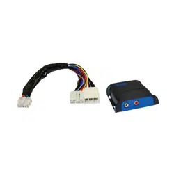
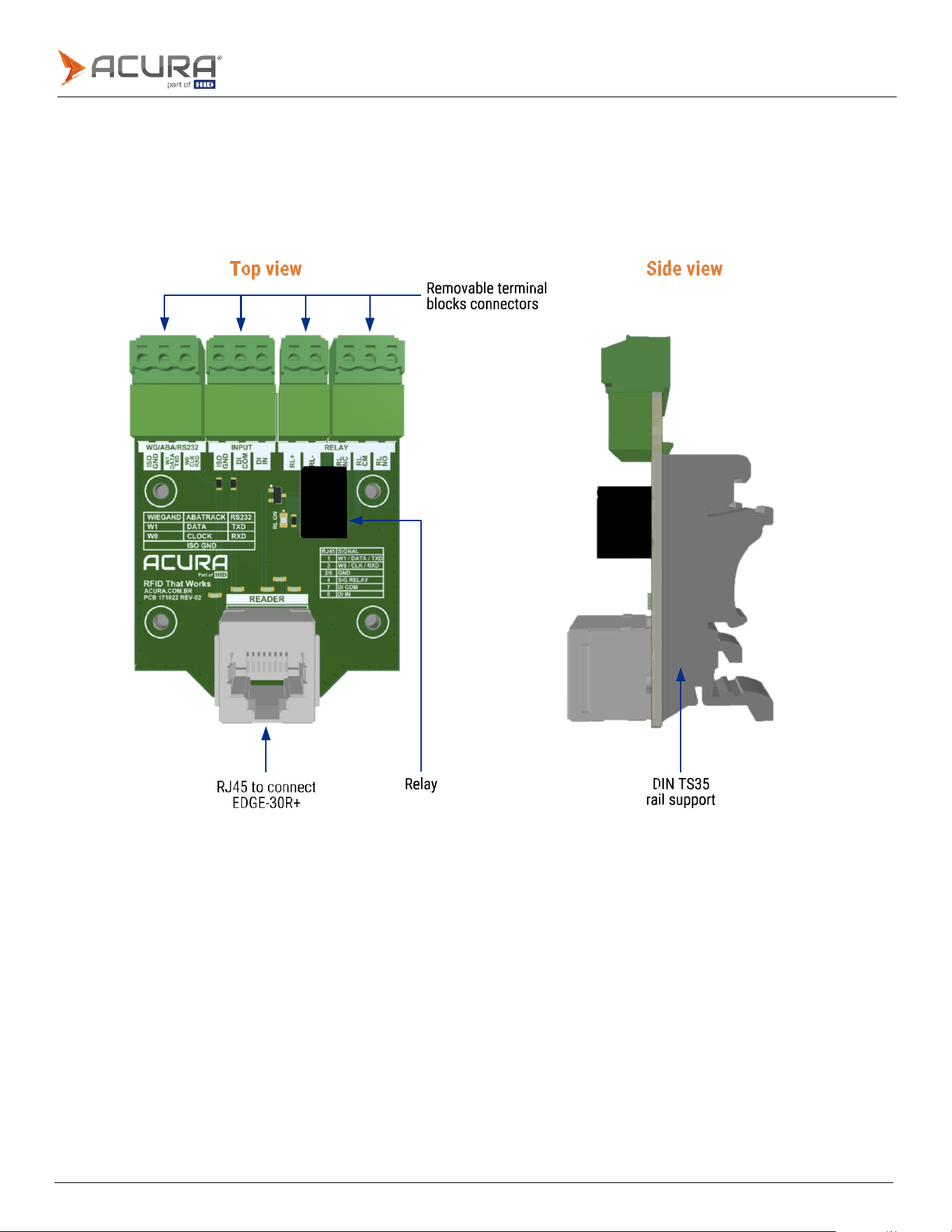
2.2
Hardware interface board
The hardware interface board is a passive printed circuit board design to help the interconnection between the EDGE-
30R+ and other devices, for example: Access Control Controllers, Sensors, and Gate Controllers.
The board was designed to be compact, occupying a minimum of panel space, and has removable terminal blocks
installed for wire connections and an RJ45 for EDGE-35 connection.
Public
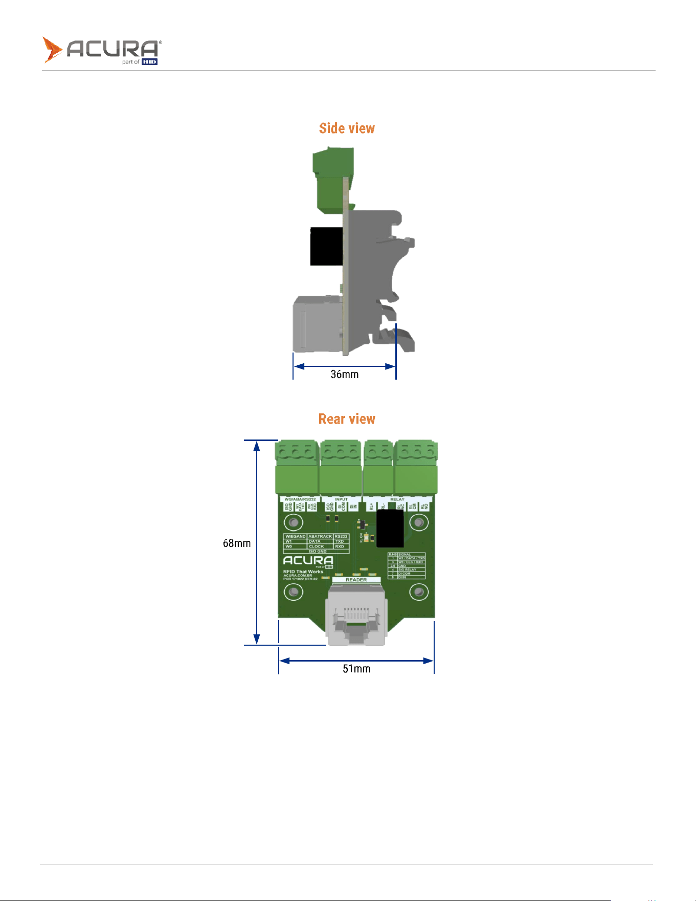
2.2.1
Dimensions

Public
2.2.2
Specification (hardware interface board)
Physical characteristics
IP
rating
Internal
use
only
Connectors
Removable
Terminal
Block
Plug
for
wires
16-30
AWG
Relay
Coil:
24VDC,
10mA
Contact
rating:
1
A,
30
VDC
at
40°C
/
0.3
A,
110
VDC
at
40°C
Dimensions
68
x
51
x
36
mm
(HxWxD)
with
Terminal
Block
Plug
connected
Weight
38g
(0.084lb)
Operation
temperature
-10ºC
to
65ºC
(14°F
to
149°F)
Storage
temperature
-10ºC
to
70ºC
(14°F
to
158°F)
Humidity
95%
Mounting
type
Compatible
with
DIN
TS35
rail
(35x7.5mm)

Public
Section
03
Installation
Public
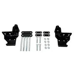
3.1
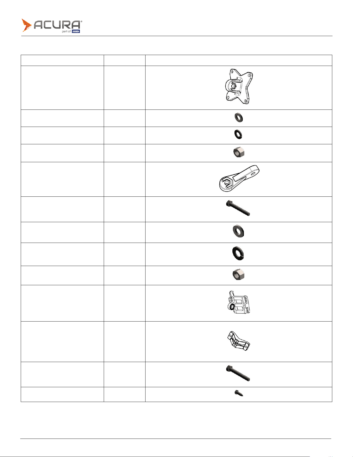
Mounting kit components
Component number
Quantity
Component image
1.
Reader
base
bracket
1
2.
Flat
washer
M5
4
3.
Spring
washer
M5
4
4. Nut M5
4
5.
Bracket
arm
1
6. Bolt M8x40
4
7.
Flat
washer
M8
4
8.
Spring
washer
M8
4
9. Nut M8
2
10.
Pole/wall
bracket
1
11.
Clamping
bracket
1
12. Bolt M8x70
2
13.
Screw
M5x16
4
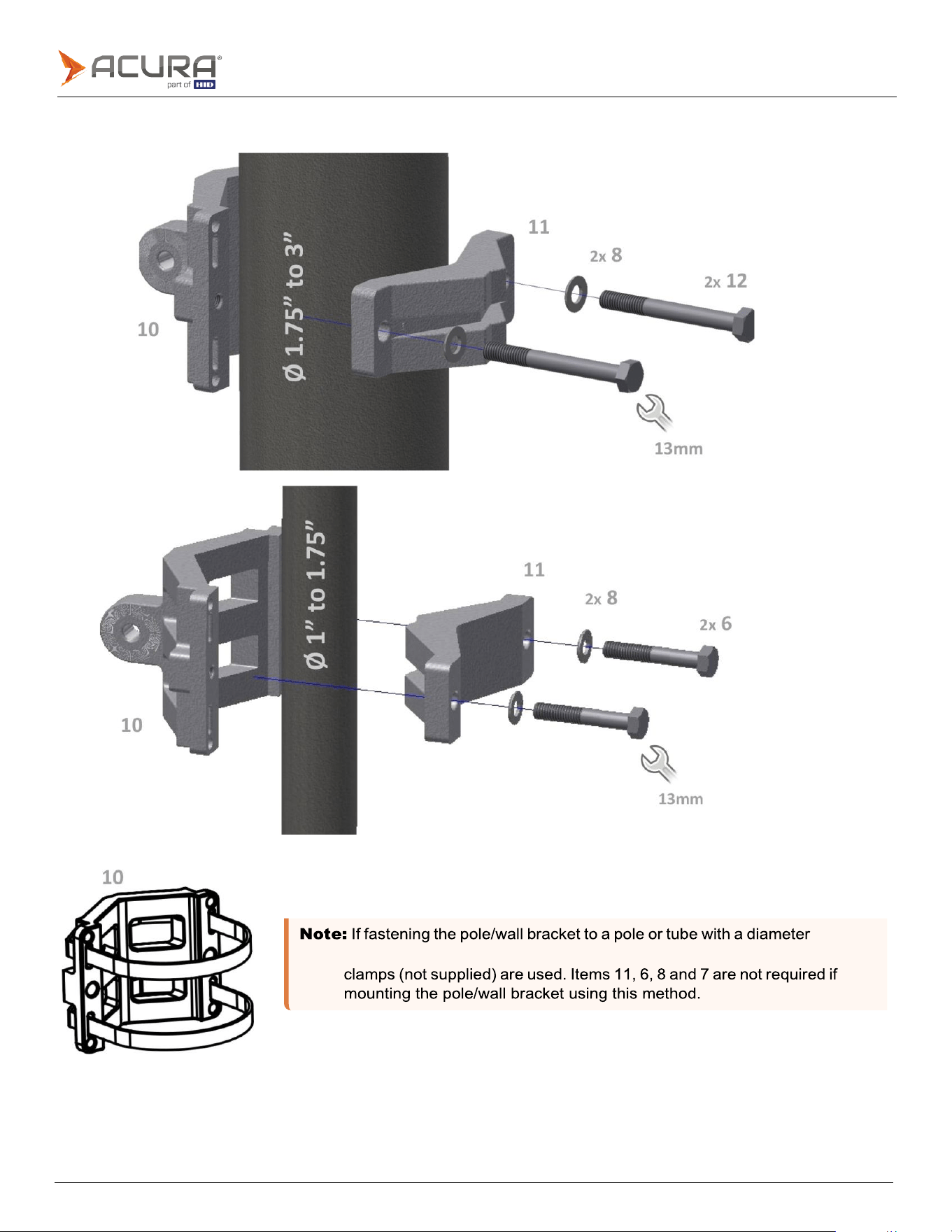
Public
exceeding 3", it is recommended that two appropriately sized screw hose
3.1.1
Mounting kit assembly
Public
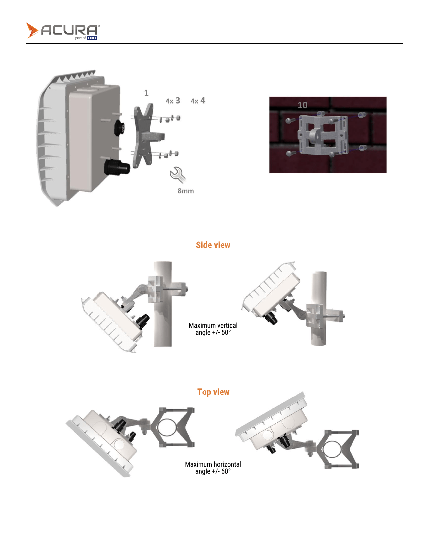
3.1.2
Mounting the EDGE-35
3.1.3
Mounting kit operational angles
Public
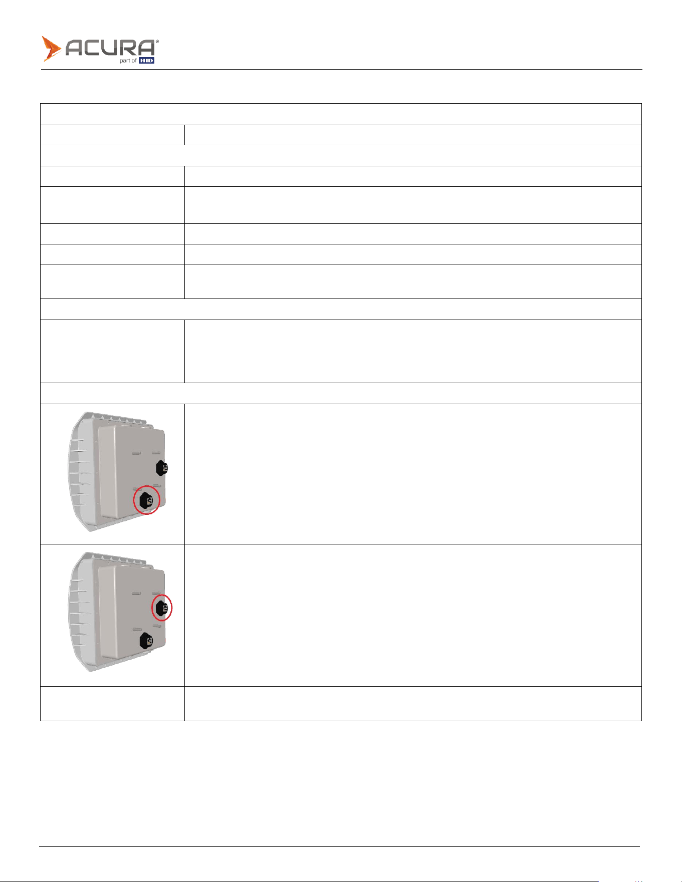
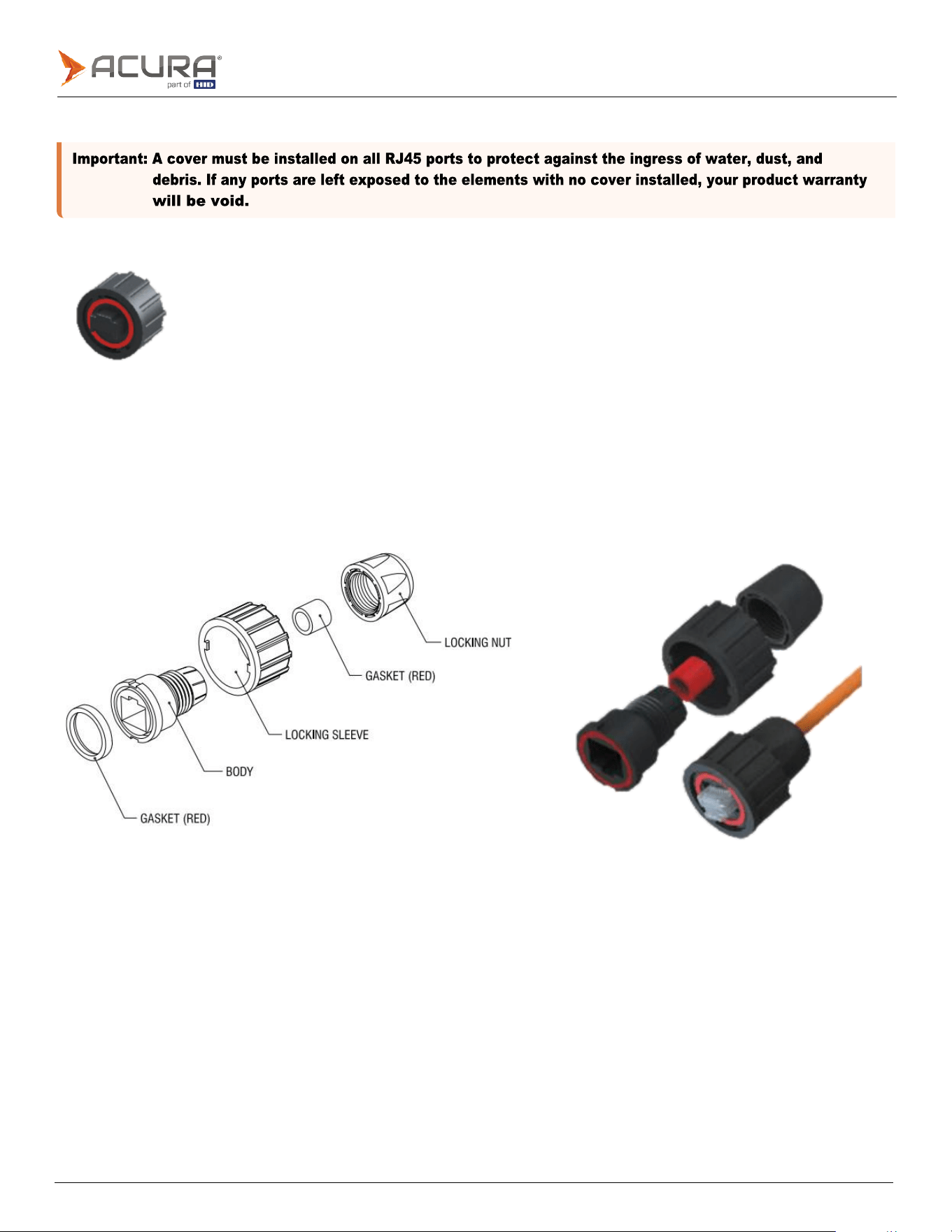
3.1.4
Unused connector cover
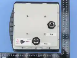
The unused connector cover must be installed to protect unused ports from the ingress of water, dust, and debris.
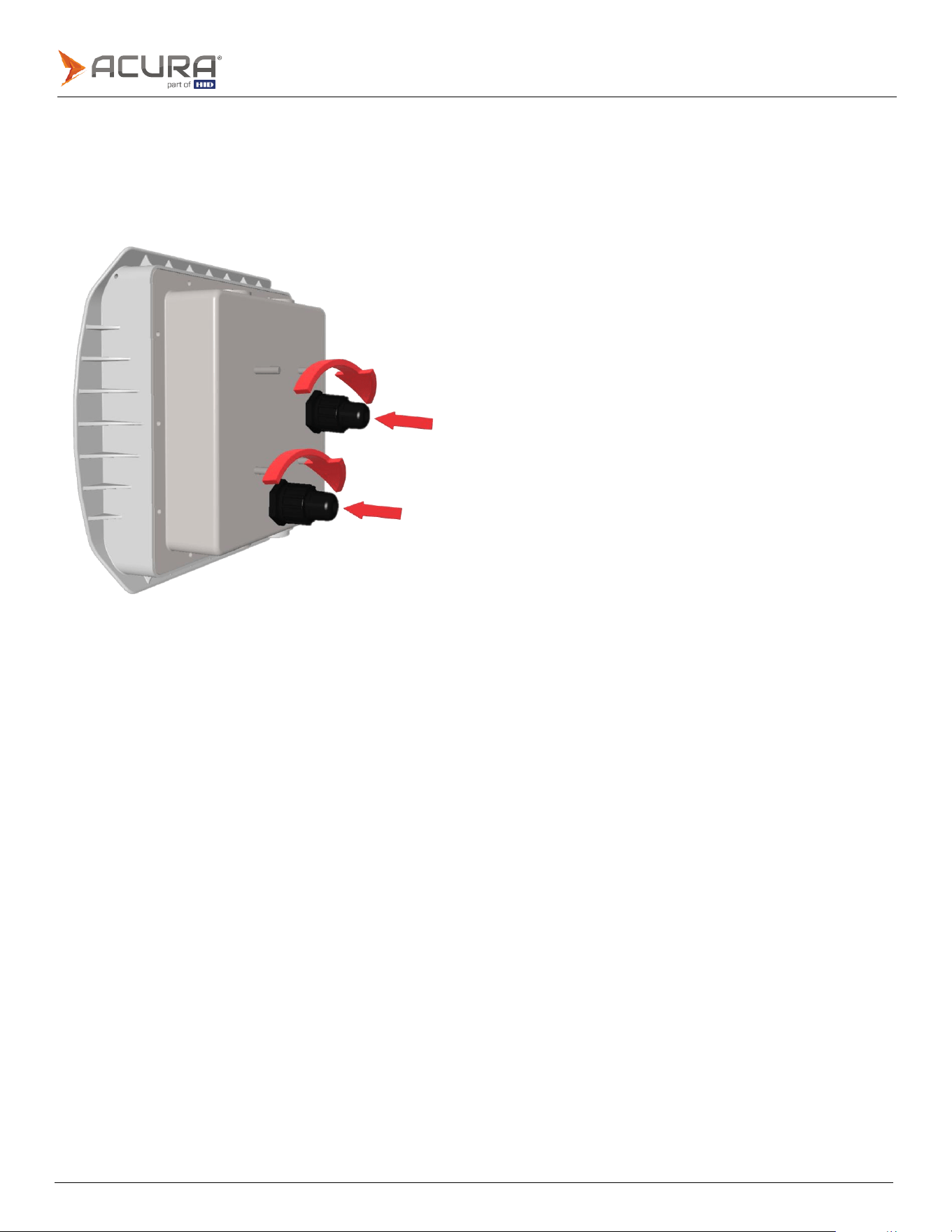
3.1.5
RJ45 Cable plug jacket
The RJ45 cable plug jacket must be used when installing RJ45 cables.
The jacket protects the units port, and installed cable from the ingress of water, dust, and debris.
Assembly
Public
Installing the RJ45 cable plug jacket
⚫
Ensure the RJ45 connector release tab is in the correct orientation before inserting it into the port.
⚫
Insert the RJ45 cable into the port, ensuring it is fully pressed in.
⚫
Rotate the plug jackets locking sleve half a turn, to fully lock the sleve into place.
⚫
Tighten the locking nut.
Public
Note:
To achieve the optimum reading performance of a passive UHF tag installed on a vehicles windshield, the
following specified measurements should be implemented.
3.2
EDGE-35 recommended installation positions
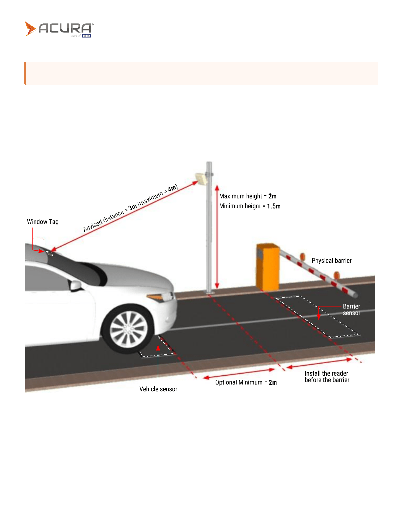
3.2.1
EDGE-35 located at the side of the lane
The angle of the reader will depend on the installation height. The front side of the reader should be pointed to where the
tag will be at the ideal reading distance of 3m, as shown. You can measure 3m from the center of the installed reader to
an average height of 1.5m from the floor where the tags will be, the reader should be pointed to this location, where the
tag should be.
Public
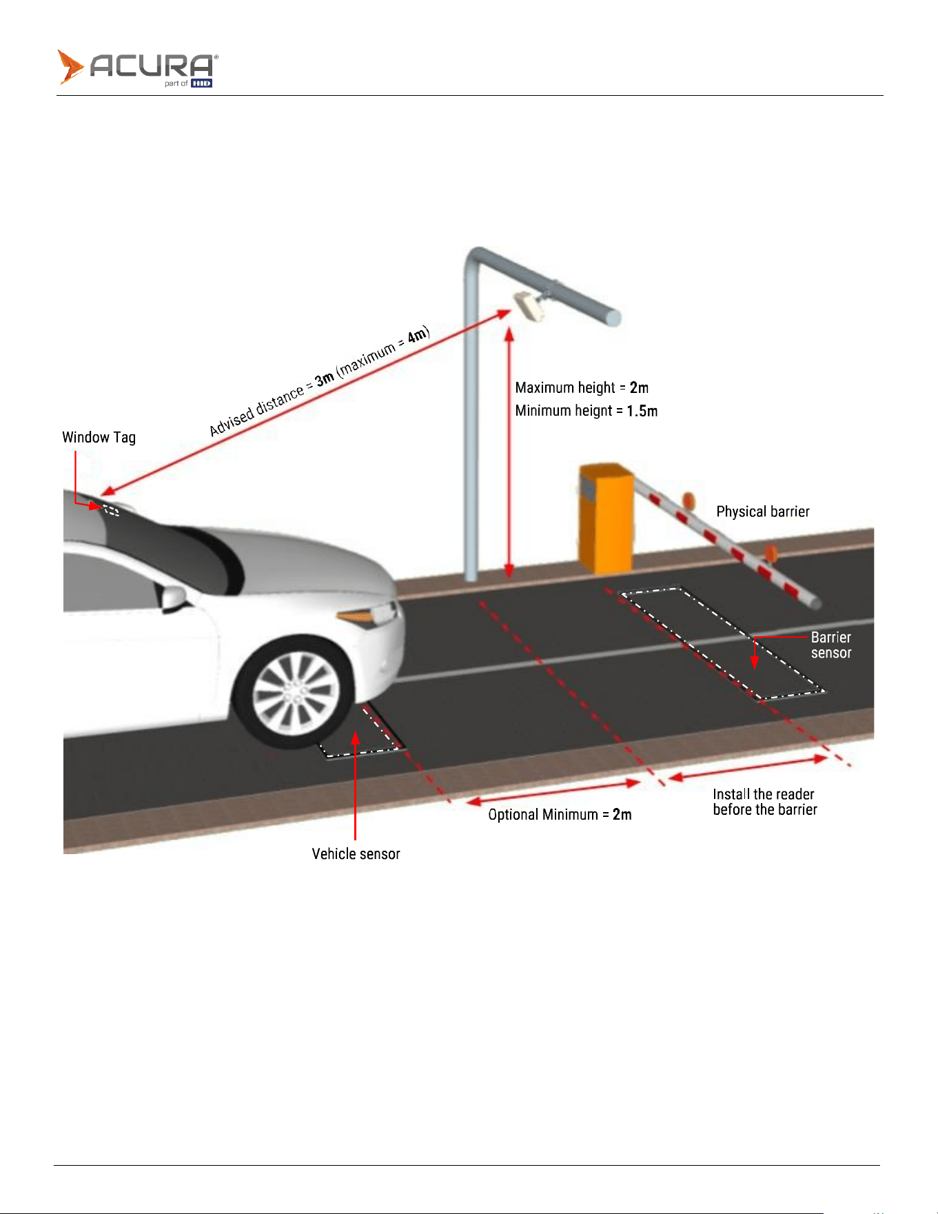
3.2.2
EDGE-35 located in the center of the lane
The angle of the reader will depend on the installation height. The front side of the reader should be pointed to where the
tag will be at the ideal reading distance of 3m, as shown. You can measure 3m from the center of the installed reader to
an average height of 1.5m from the floor where the tags will be, the reader should be pointed to this location, where the
tag should be.
Public
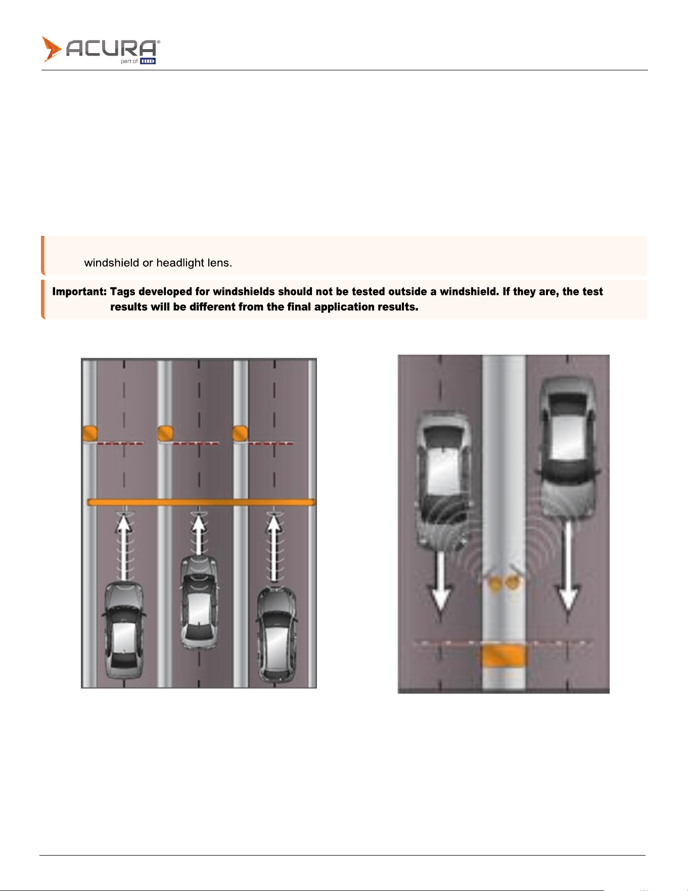
Note:
All tag reading tests must be performed with the tag correctly installed in the vehicle, for example, on the
3.3
Troubleshooting - tag reading
When there is a multi-lane highway that require tags to be read in each lane, tag readings may inadvertently be taken
from vehicles in other lanes.
To minimize the occurrence of unwanted tag reads as much as possible, the following may be performed:
1.
Filter unwanted side/adjacent readings, by using the Filter by tag signal level RSSI parameter.
2.
Adjusting the reading power combined with the RSSI filter. In many cases the reading power can be decreased
without compromise tag reading on the correct lane or position.
3.
Adjusting the installation angle of the reader.
Examples of multi-lane installations
Public
Indicates an internal error.
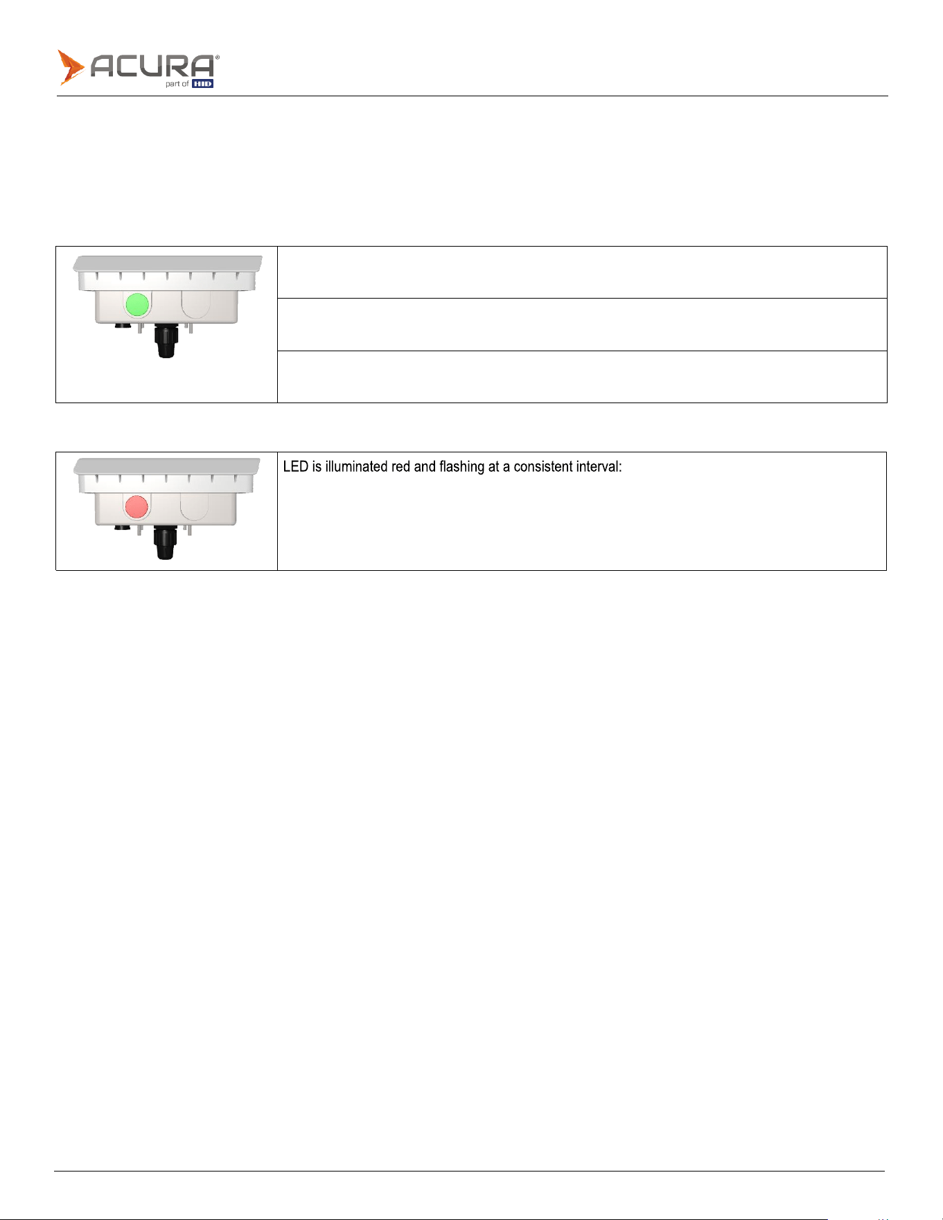
3.4
Reader operation - visual feedback
Located on the bottom side of the reader case, there is an operating status lens containing a green and red LED.
The LED lens will display one of four different status messages, using either the green or red LED:
Green LED illumination status message
LED is illuminated solid green:
Indicates tag reading
LED is illuminated green and flashing at a consistent interval:
Indicates continuous reading mode.
LED is solid green, gives one flash, then repeats sequence (solid, flash, solid, flash):
Indicates trigger reading mode.
Red LED illumination status message

Public
3.5
Installation check list
Check the Ethernet cable pinout, both sides, according to the chosen standard, and the RJ45 crimp quality, as
in Port pinout section.
If using the Serial interface (Wiegand/Clock-and-Data or RS-232) check the electrical connections between
reader and your Controller board [W0 <-> W0, W1 <-> W1, TXD <-> RX, RXD <-> TX…] and so on.
Check if all Cable Plug Jacket or RJ45 Cover are well connected and locked, as in RJ45 Cable plug jacket
section.
Check on the back of the Cable Plug Jacket if the locking nut is fastened.
Take note or a photo of the side label of the reader that contains the MAC address and serial number.
Make sure all screws are tight, following the Mounting kit assembly section.

Public
Section
04
Electrical
Public
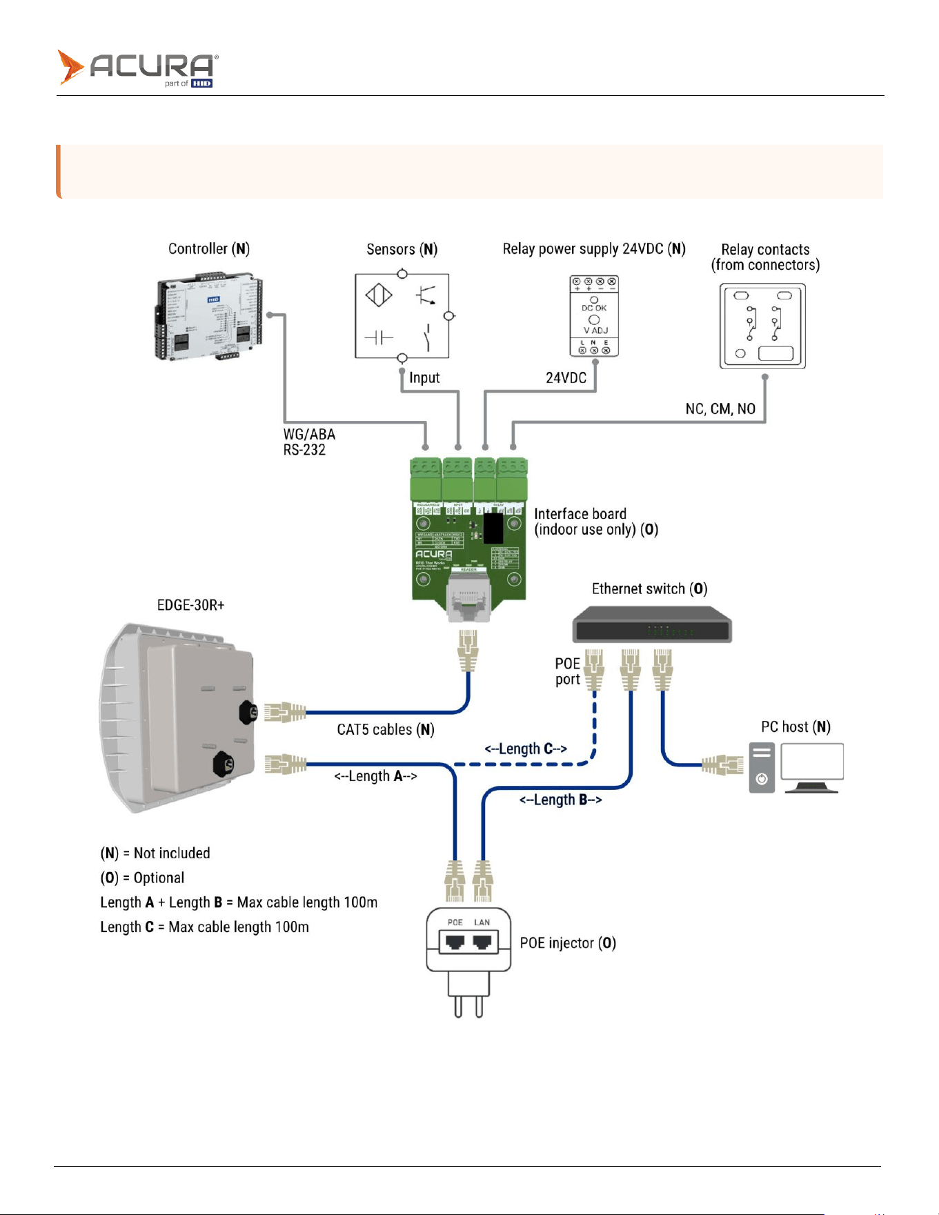
Note:
The POE Injector can be replaced by an Ethernet Switch with POE port supporting IEE 802.3af standard.
The 24VDC power supply is only required if the Relay will be used.
4.1
Connection diagram
Public
Note:
All pins are electrically isolated. Either T568A or T568B standard can be used.
4.2
Port pinout
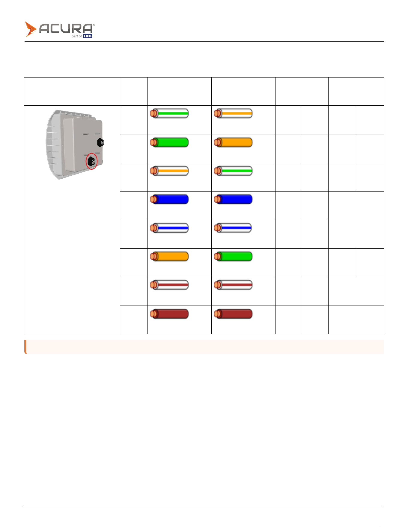
4.2.1
POE port pinout
POE port
Pins
T568A color
T568B color
10/100 mode
B DC on
spares
10/100 mode A
mixed DC and
data
Pin
1
White/green
stripe
White/orange
stripe
RX+
RX+
DC+
Pin
2
Green
solid
Orange
solid
RX-
RX-
DC+
Pin
3
White/orange
stripe
White/green
stripe
TX+
TX+
DC-
Pin
4
Blue
solid
Blue
solid
DC+
Unused
Pin
5
White/blue
stripe
White/blue
stripe
DC+
Unused
Pin
6
Orange
solid
Green
solid
TX-
TX-
DC-
Pin
7
White/brown
stripe
White/brown
stripe
DC-
Unused
Pin
8
Brown
solid
Brown
solid
DC-
Unused
Public
Note:
All pins are electrically isolated. Either T568A or T568B standard can be used.
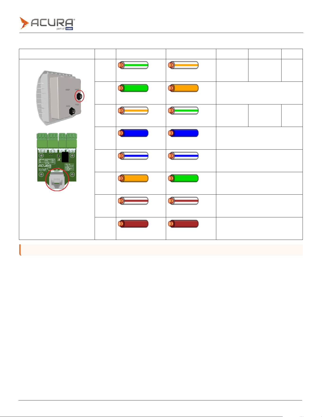
4.2.2
SIG port pinout
SIG port
Pins
T568A color
T568B color
Wiegand
Abatrack
RS-232
Pin
1
White/green
stripe
White/orange
stripe
W1
DATA
TXD
Pin
2
Green
solid
Orange
solid
ISO
GND
Pin
3
White/orange
stripe
White/green
stripe
W0
CLK
RXD
Pin
4
Blue
solid
Blue
solid
DIG
OUT
RELAY
Pin
5
White/blue
stripe
White/blue
stripe
Not
used
Pin
6
Orange
solid
Green
solid
ISO
GND
Pin
7
White/brown
stripe
White/brown
stripe
DI
COM
Pin
8
Brown
solid
Brown
solid
DI
IN
Public
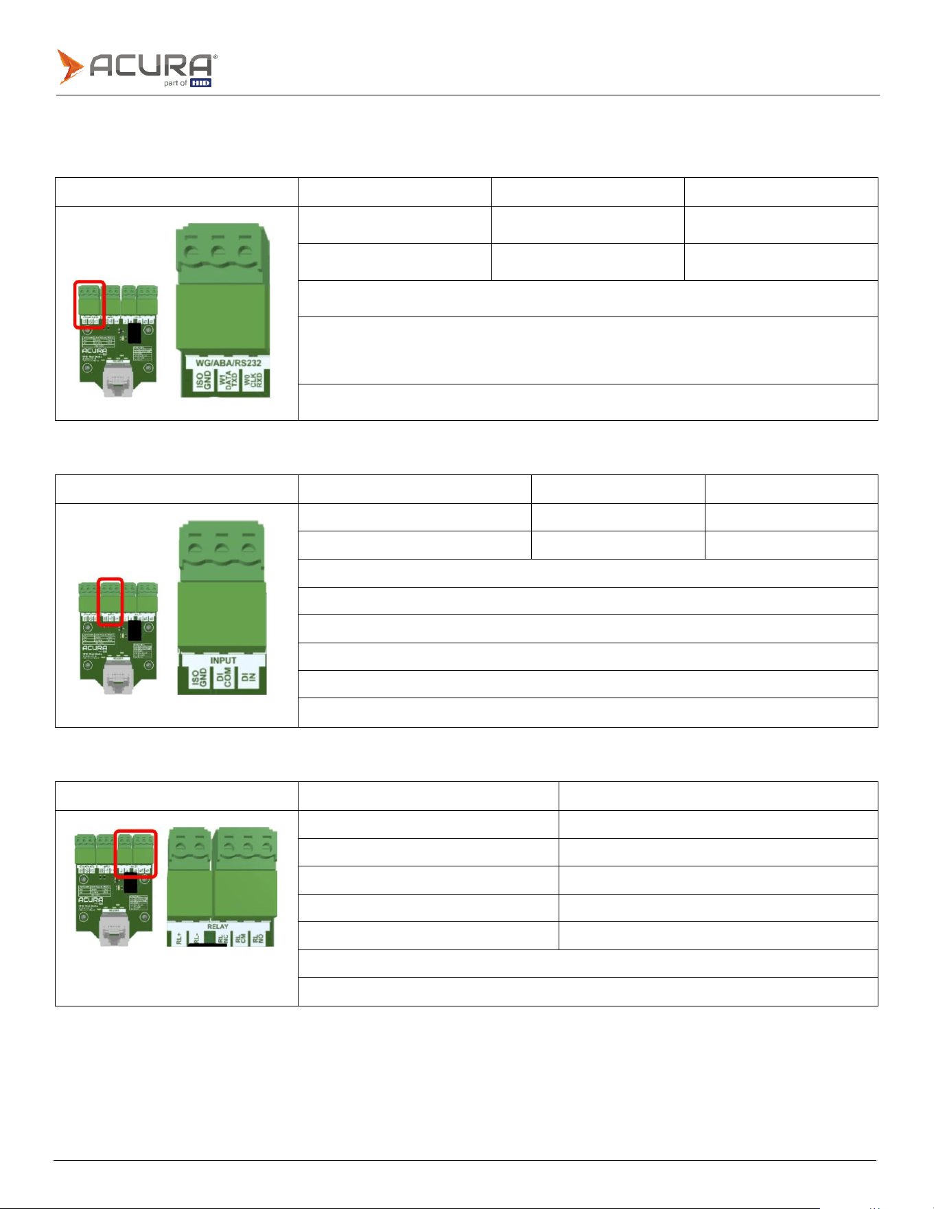
4.3
Interface board connections
4.3.1
Wiegand/Abatrack/RS-232
Interface board
WIEGAND pins
Clock-and-Data pins
RS-232 pins
W1
(output)
DATA
(output)
TXD
(output)
W0
(output)
CLOCK
(output)
RXD
(input)
ISO
GND
(reference)
To avoid noise coupling that may compromise the communication integrity between the reader
and the Controller/PC, avoid passing the cable near power supply, lamp reactors, electrical
power cables or other electromagnetic noise sources.
Maximum
cable
length
15m.
4.3.2
Digital input (sensors)
Interface board
Dry Contact output sensor
NPN output sensor
PNP output sensor
ISO
GND
DI
COM
DI
COM
DI
IN
DI
IN
DI
IN
Minimum
pulse
width:
100ms.
High
Level
(+3.0
to
+24.0VDC)
Low
Level
(0
to
+2.0VDC)
Maximum
voltage
in
NPN
and
PNP
is
+24VDC
The
input
signal
debouncing
is
fixed
in
500ms.
Maximum
recommended
cable
length
30m.
4.3.3
Output (Relay)
Interface board
Pins
Description
RL+
Positive
from
external
24VDC
power
supply
RL-
GND
from
external
24VDC
power
supply
RL
NC
Relay
Normally
Closed
pin
RL
CM
Relay
Common
pin
RL
NO
Relay
Normally
Open
pin
To
use
the
on-board
relay,
an
external
+24VDC
power
supply
is
required.
Maximum
recommended
cable
length
30m.

Public
Revision history
Date
Description
Revision
October
2025
Minor
updates
to
specifications.
A.2
October
2025
Document
renamed
to
EDGE-35
Hardware
Install
Guide.
A.1
October
2025
Initial
release.
A.0