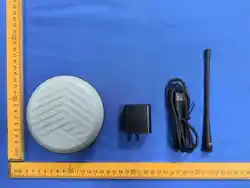
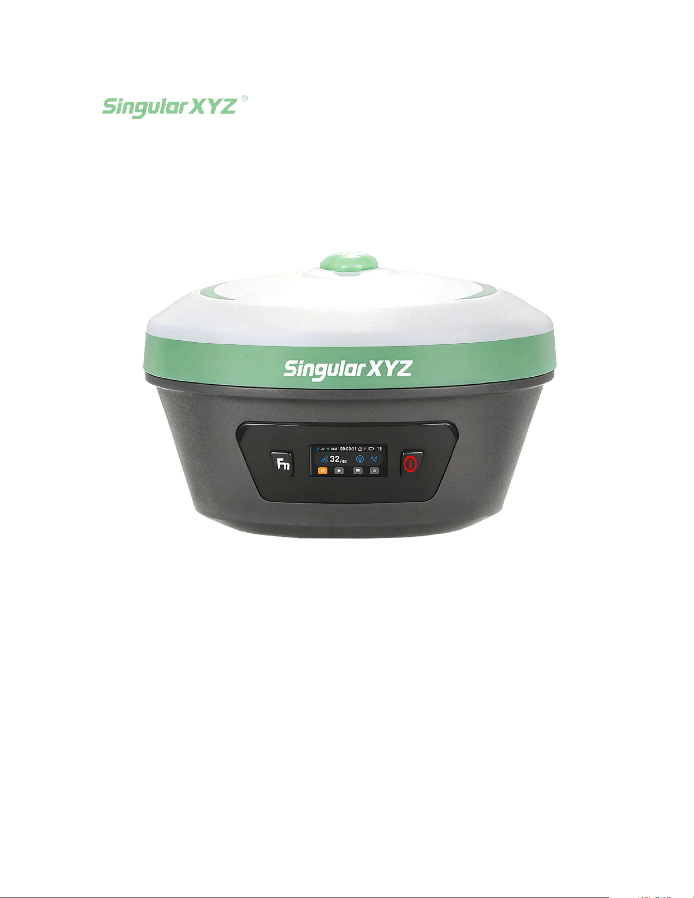
Xbase GNSS Receiver User Manual
2026.01.30V1.0
CONTENTS
1 INTRODUCTION..............................................................................................................................................1
1.1 About the Receiver......................................................................................................................1
1.2 Lower Housing..............................................................................................................................1
1.3 Front Panel Operation............................................................................................................... 2
2 RTKWORKFLOW............................................................................................................................................7
2.1 About Software............................................................................................................................. 7
2.1.1 Installation of SingularPad................................................................................................................7
2.1.2 Software Registration..........................................................................................................................7
2.2 Create a New Project..................................................................................................................8
2.3 Device connection.....................................................................................................................12
2.3.1 NFC connection....................................................................................................................................12
2.3.2 Bluetooth connection........................................................................................................................13
2.4 Concepts About RTK................................................................................................................16
2.4.1 Overview................................................................................................................................................ 16
2.4.2 High real-time precision..................................................................................................................16
2.4.3 Corrections over NTRIP...................................................................................................................17
2.5 Quick Setup Your Receiver....................................................................................................18
2.5.1 Internal Radio Mode..........................................................................................................................19
2.5.2 Network Mode..................................................................................................................................... 25
2.5.3 PPP MODE..............................................................................................................................................36
2.5.4 SBAS MODE...........................................................................................................................................36
3 RTK SURVEY - FIELD DATA COLLECT......................................................................................................38
3.1 SingularPad Top Status Bar Introduction......................................................................38
3.2 Point Survey.................................................................................................................................39
3.3 Calibrate Point............................................................................................................................44
3.4 Localization..................................................................................................................................46
3.5 Tilt Survey.................................................................................................................................... 51
3.6 Point Stakeout.............................................................................................................................53
3.7 Export points data....................................................................................................................54
4 STATIC SURVEY.............................................................................................................................................57
4.1 Static Data Collection..............................................................................................................57
4.2 Static Data Download..............................................................................................................60
4.3 RINEX Convert............................................................................................................................61
5 WEB UI INTRODUCTION............................................................................................................................63
5.1 Access the web interface....................................................................................................... 63
5.2 Work Management...................................................................................................................64
5.3 Firmware Upgrade................................................................................................................... 65
6 TROUBLESHOOTING...................................................................................................................................66
6.1 How to Find Serial Number..................................................................................................66
6.2 How to Get Debug Data & Project File............................................................................ 66
6.2.1 Save Debug File................................................................................................................................... 66
WARRANTY CARD...........................................................................................................................................69
Warning and Caution.....................................................................................................................................69
Warranty Notice..............................................................................................................................................70
1
1 INTRODUCTION
The SingularXYZ Xbase GNSS Receiver (referred to as Xbase) User Manual is
intended to help you get familiar with the Xbase receiver and start your project
effectively. We highly recommend that you read this manual before you start your
project, even if you have previous experience with other GNSS RTK receivers before.
1.1 About the Receiver
As a full-featured RTK solution, the Xbase is designed to deliver outstanding
performance while maintaining a compact and lightweight design. It offers
comprehensive enhancements in key aspects such as multiple work modes, 25km
extended-range UHF, and a built-in web interface. Xbase GNSS receiver is a
professional GNSS base station. The working performance is close to GNSS receiver
with an external radio, but user does not need to carry a heavy external battery, an
external radio and a radio antenna. The built-in 5W radio enables up to 25 km
operating range under ideal conditions. Powered by a 1408-channel GNSS engine,
Xbase supports full-constellation tracking with strong anti-interference
performance, delivering stable, high-quality correction data for reliable RTK
operation in challenging field environments.
1.2 Lower Housing
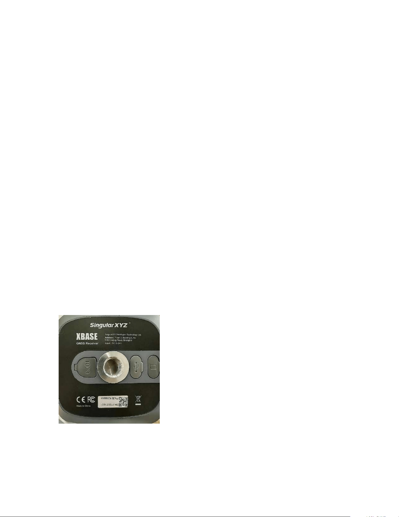
The lower housing of the receiver contains a serial port, a USB port, and a SIM card
slot. The antenna used for radio communication is located on the top of the device.
IMPORTANT NOTICE:
If the receiver is not used for an extended period, it is recommended to charge it every three months to
prevent potential damage to the lithium battery cells.
2
1.3 Front Panel Operation
(1) Hardware Button Description
The device uses two physical buttons to simulate a scroll wheel for interaction.
• Power button: Used for confirm/execute key (The push function for the scroll
wheel)
• Fn key (function key): Used for navigation control. Single click scrolls the wheel
down, double click scrolls the wheel up.
(2) General Interaction Logic
In all pages except the "parameter selection interface" (such as the homepage, menu
page, and switch page), the operation logic is consistent as follows:
Switch focus (navigation): Press the Fn key (use the scroll wheel to switch
focus).
-Switch focus between different options on the screen.
Confirm/Select: Power button (scroll wheel push button).
-Function: Confirm current action
(3) Detailed operation guide for the page
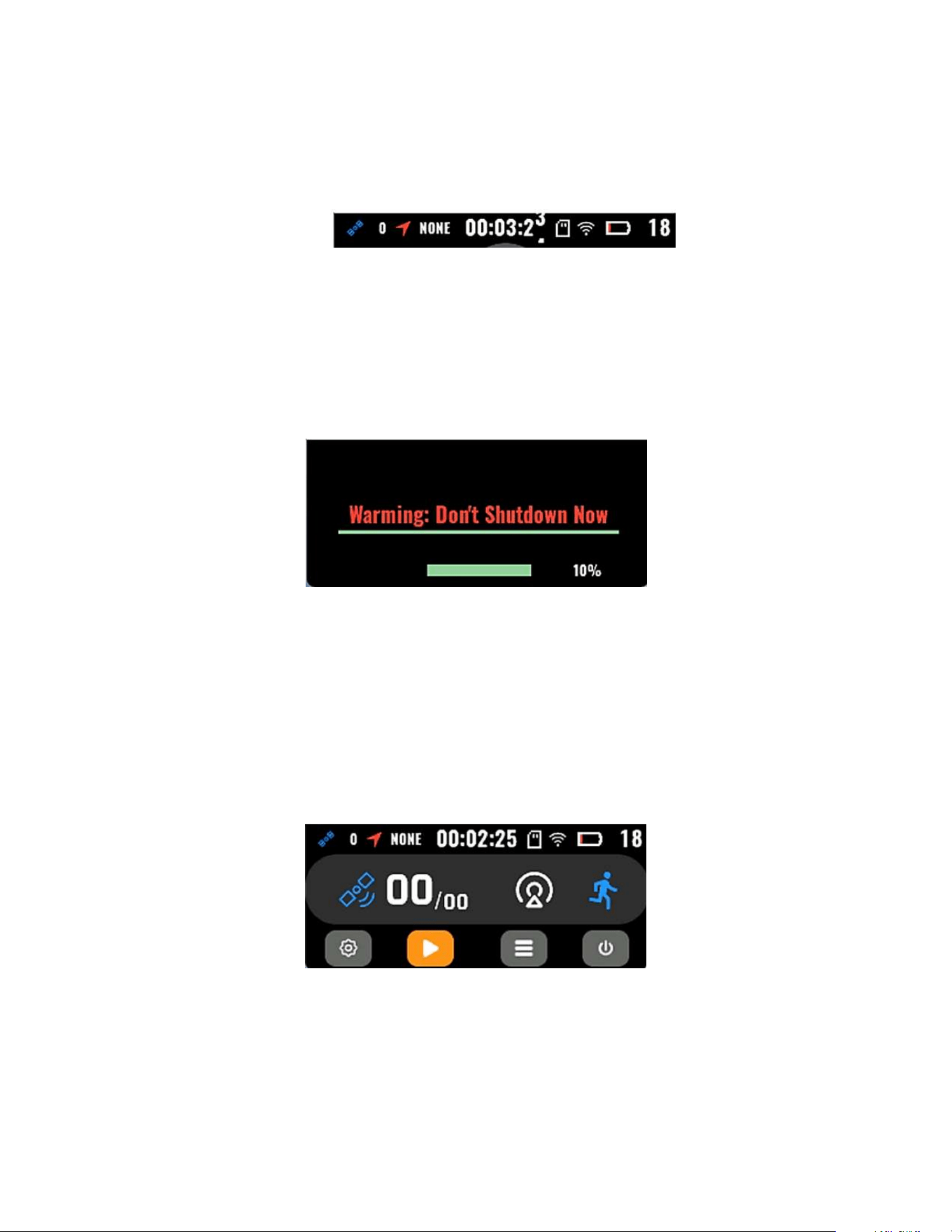
①Charging interface
When the device is powered and the main page is not active, the top status bar will
automatically slide down and appear after 10 seconds of inactivity.
3
Interface description: No component switching is available on this
interface; there is only one button component, which is the default focus. On
this screen, the device can only be powered on by pressing the power button.
Top status bar: The top status bar displays the following items in sequence:
number of satellites used, positioning status, operating time, static status, Wi-
Fi status, and battery status.
Operation method: Press and hold the push button until the progress bar
reaches 100%. Then hen complete the operation.
② Hardware Check Page
Interface description: After the power-on logo appears, a hardware check
will be performed The MCU may exit the self-check process earlier once
communication with the mainboard has been established. ). During this time,
the scroll wheel push function will be disabled.
③ Main Standby Page
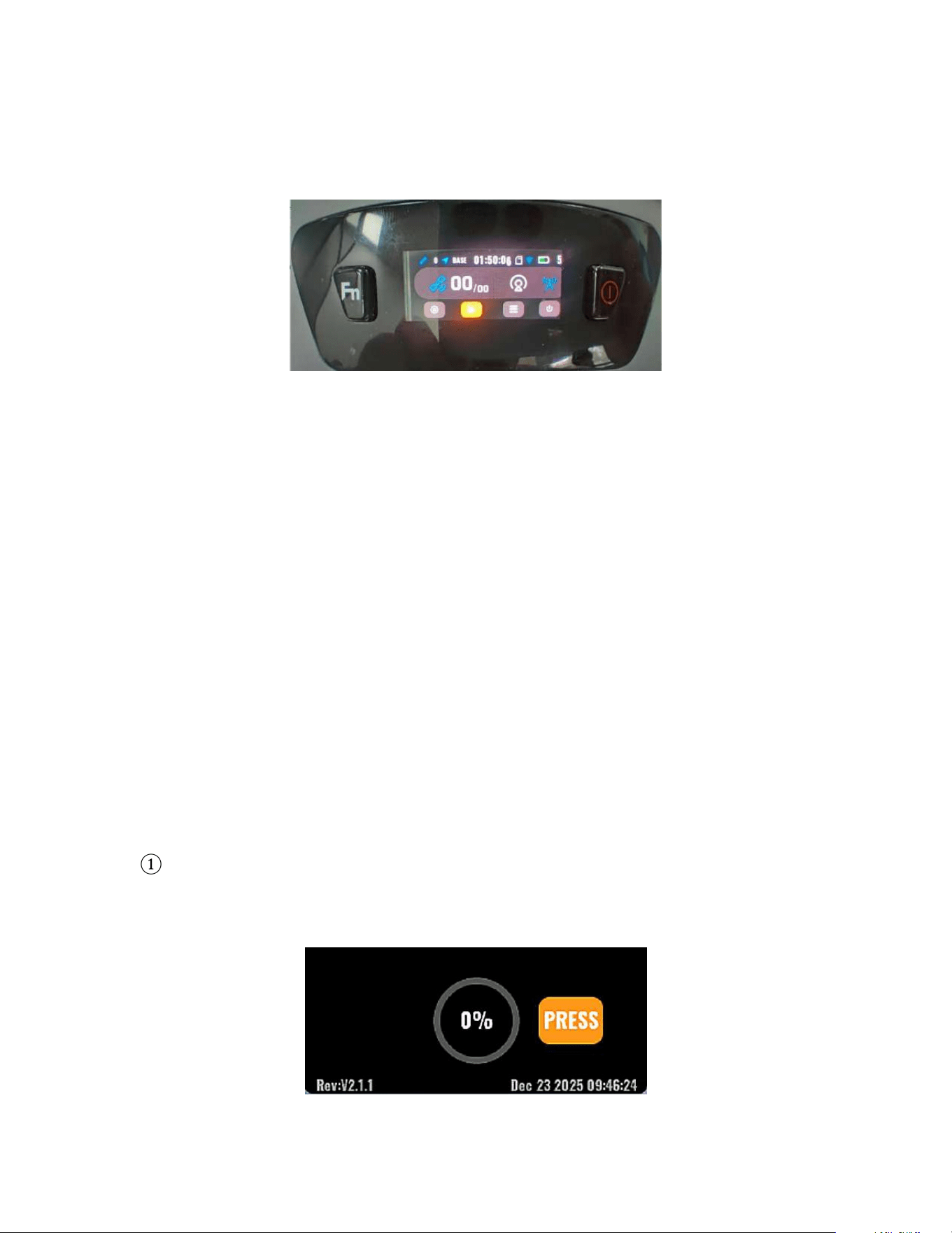
Interface description: Used to display operating information, including
number of satellites acquired, radio operating status, board operating mode.
The top status bar will remain active after power-on.
Bottom button bar: From left to right are
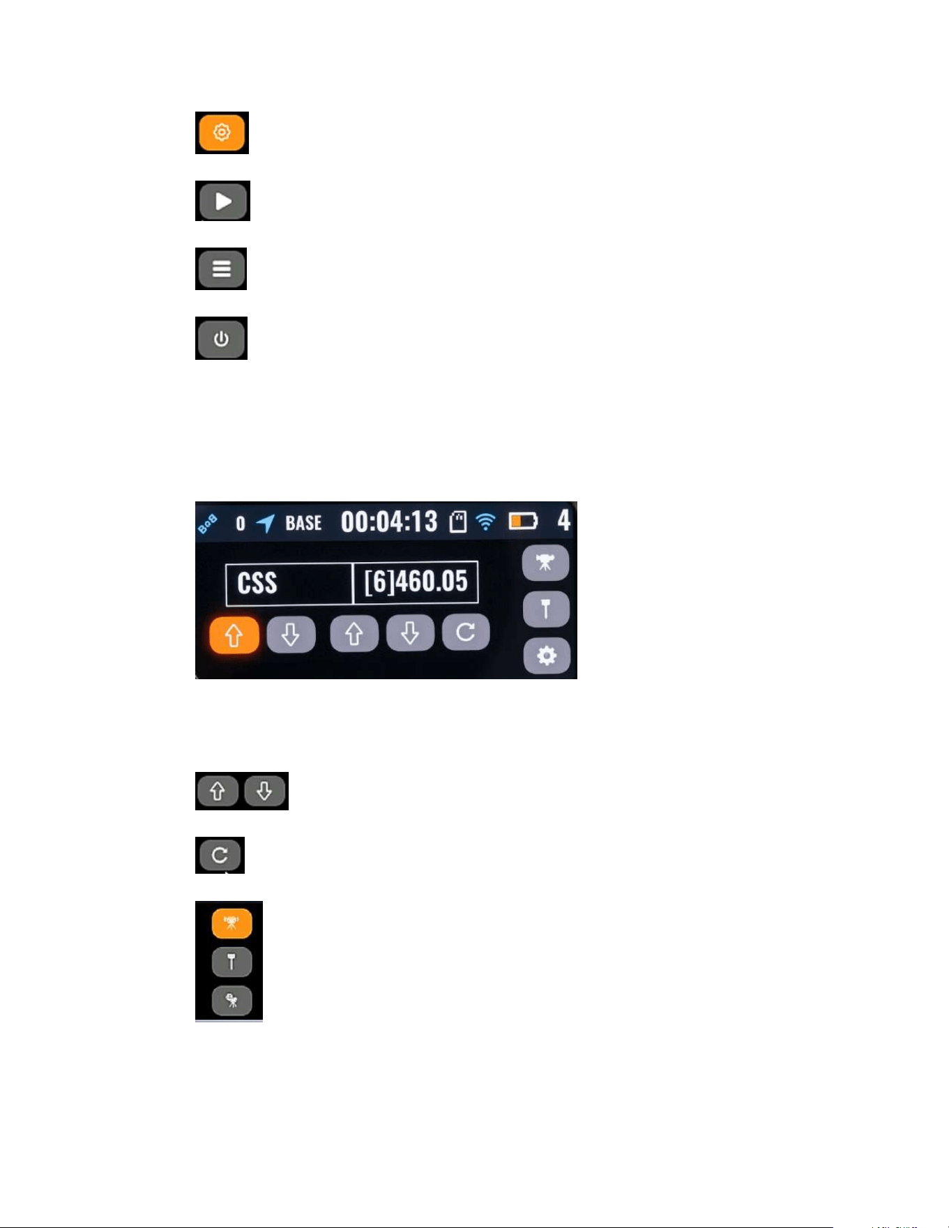
4
Working mode settings and switching
Static data acquisition switch
View current system parameters
Power off
Operating instructions: Press the Fn key to move the focus between menu
items. Press the Power button to confirm the selected function.
④ Radio Parameter Adjustment Page
Interface description: Contains a configuration list of options (such as
frequency Freq, protocol Prot).
Used for switching up and down.
Used for reset protocol and channel options
Available operating modes include: Base Station, Mobile station,
and Network Base Station.
5
Operating instructions: Press the Fn key to move the selection focus. Press
the Power button to confirm the selected option.
Save Settings: After selecting the radio protocol and channel, simply choose
the configured working mode. No further confirmation of the radio protocol
and channel is required; the settings displayed in the radio protocol and
channel boxes on the current page will reflect the configured settings.
⑤ System Parameters Page
Interface description
This page displays the following system parameters (working mode): current
GPS location coordinates, WIFI working mode and IP, battery information,
static storage information, and front panel system information.
Operating instructions:
1. Press the Fn key to browse through the available information.
2. Press the Power button to return to the previous page.
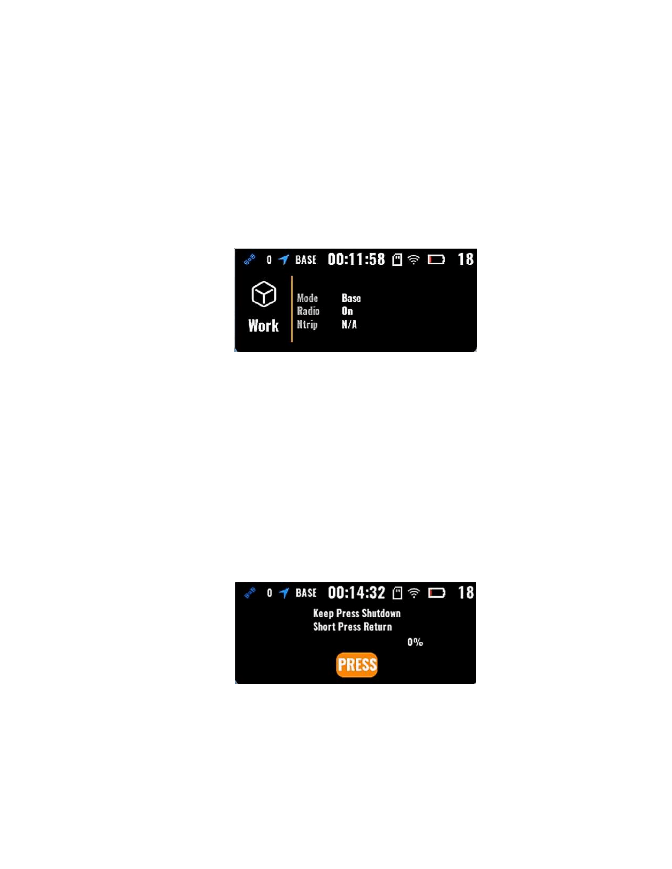
⑥ Power Off Page
Interface description: This page is used for powering off, Only one button is
available, and it is selected by default.
Press and hold the button until 100%, then go back to power off.

6
Short press to return to the main page.
Operating instructions:
Force shutdown: Press and hold the Fn key for several seconds from any
interface to force the receiver to shut down.

7
2 RTK WORKFLOW
This chapter introduces how to conduct an RTK Survey with SingularPad Software.
SingularPad is a professional Android-based surveying software developed by
SingularXYZ team.
SingularPad is fully functional as a field surveying software, equipped with complete
work modes and necessary functions for surveyors.
2.1 About Software
2.1.1 Installation of SingularPad
SingularPad has been pre-installed on SingularXYZ data collector before shipping. If
you want to download on your own device, please contact SingularXYZ for
installation support.
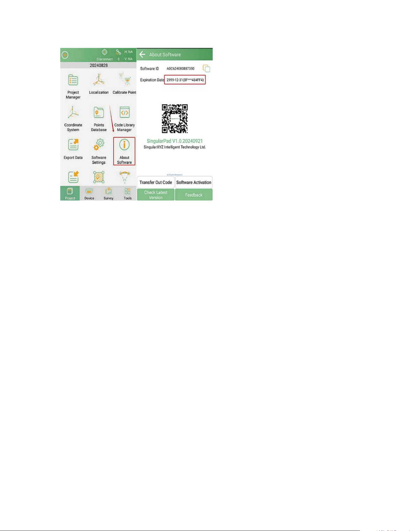
2.1.2 Software Registration
After the software is installed, you can check your software registration status
(network connection required) by following these steps:
Go to Project >> About Software and check the Expiration Date.
• If it shows 2999-12-31, this indicates a permanent registration of the software.
• If it shows Inactivated, please click Software Activation, then enter a valid
permanent license to register and activate all software functions.
8
NOTE:
If you do not have an activation code, please contact our sales or support team, providing your order
details and software ID to obtain it.
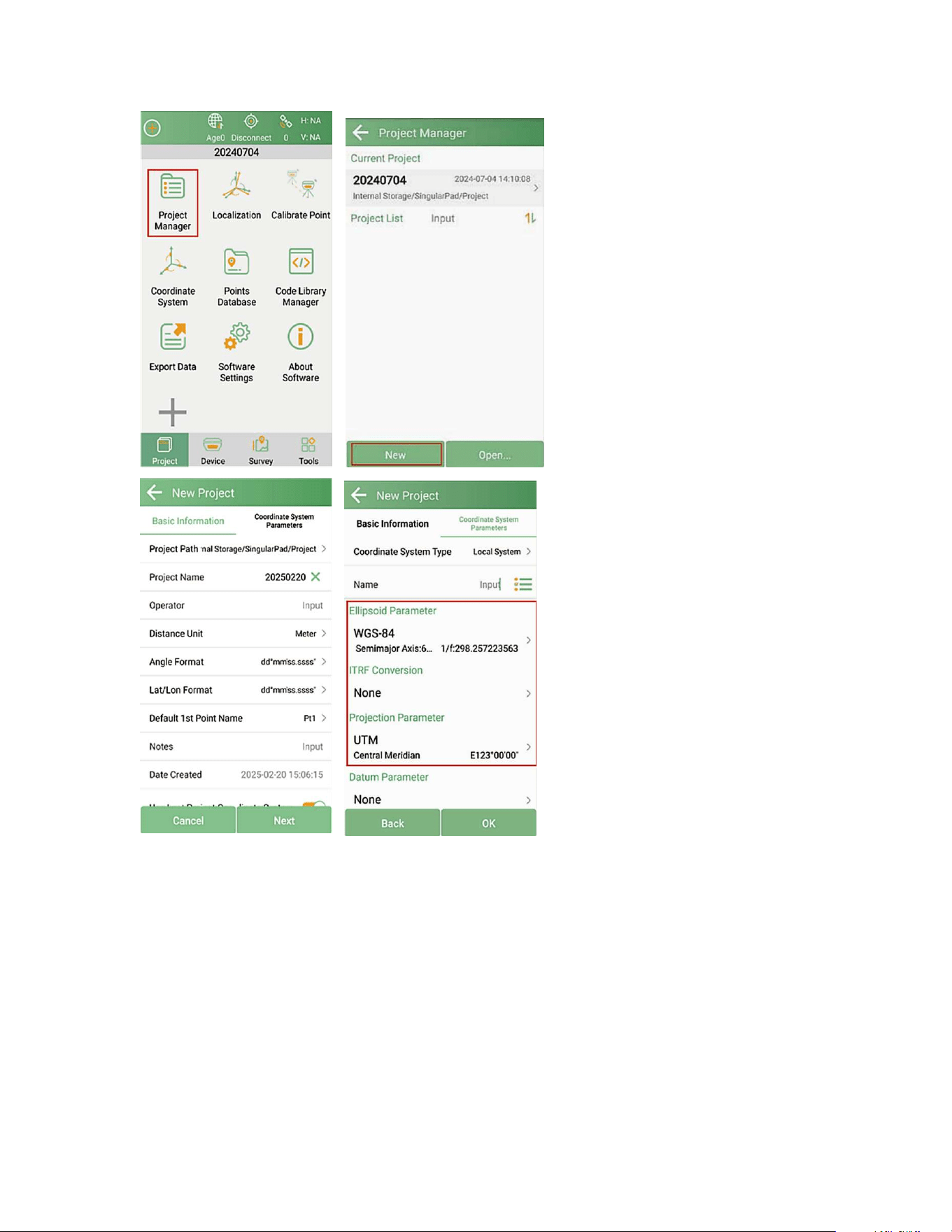
2.2 Create a New Project
Click Project Manager, click New to create a new project file and input project
name, set coordinates systems parameters and click OK to save the project.
9
NOTE:
SingularPad includes pre-defined coordinate systems for most countries and regions. You can find the
coordinate system you need by filtering the country name or searching the coordinate system name.
The following steps demonstrates how to find the predefined coordinate system you
need in SingularPad software.
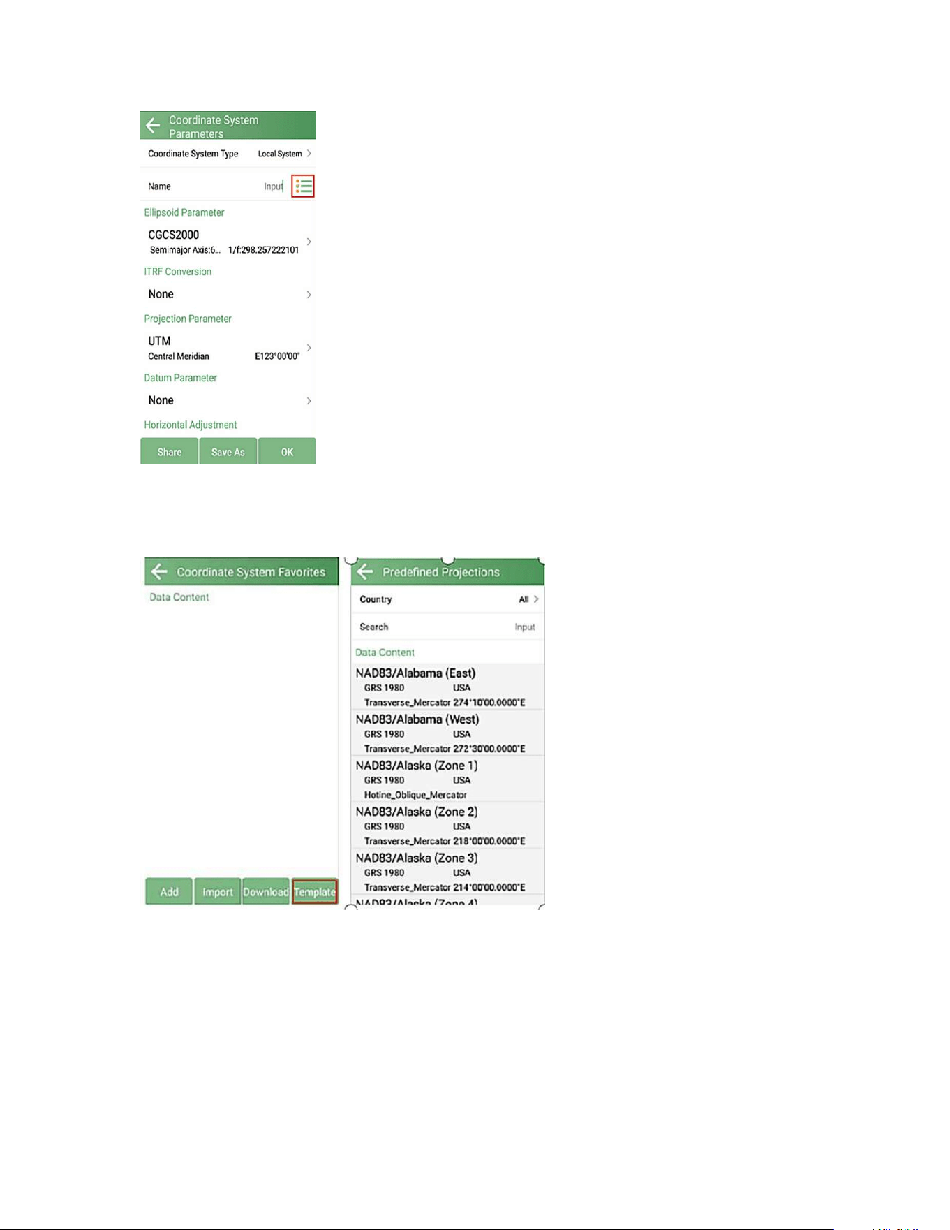
1. Click the button located after Name in Coordinate System Parameters interface.
10
2. In the Coordinate System Favorites interface, click the Template below to enter
the Predefined Projections interface.
11
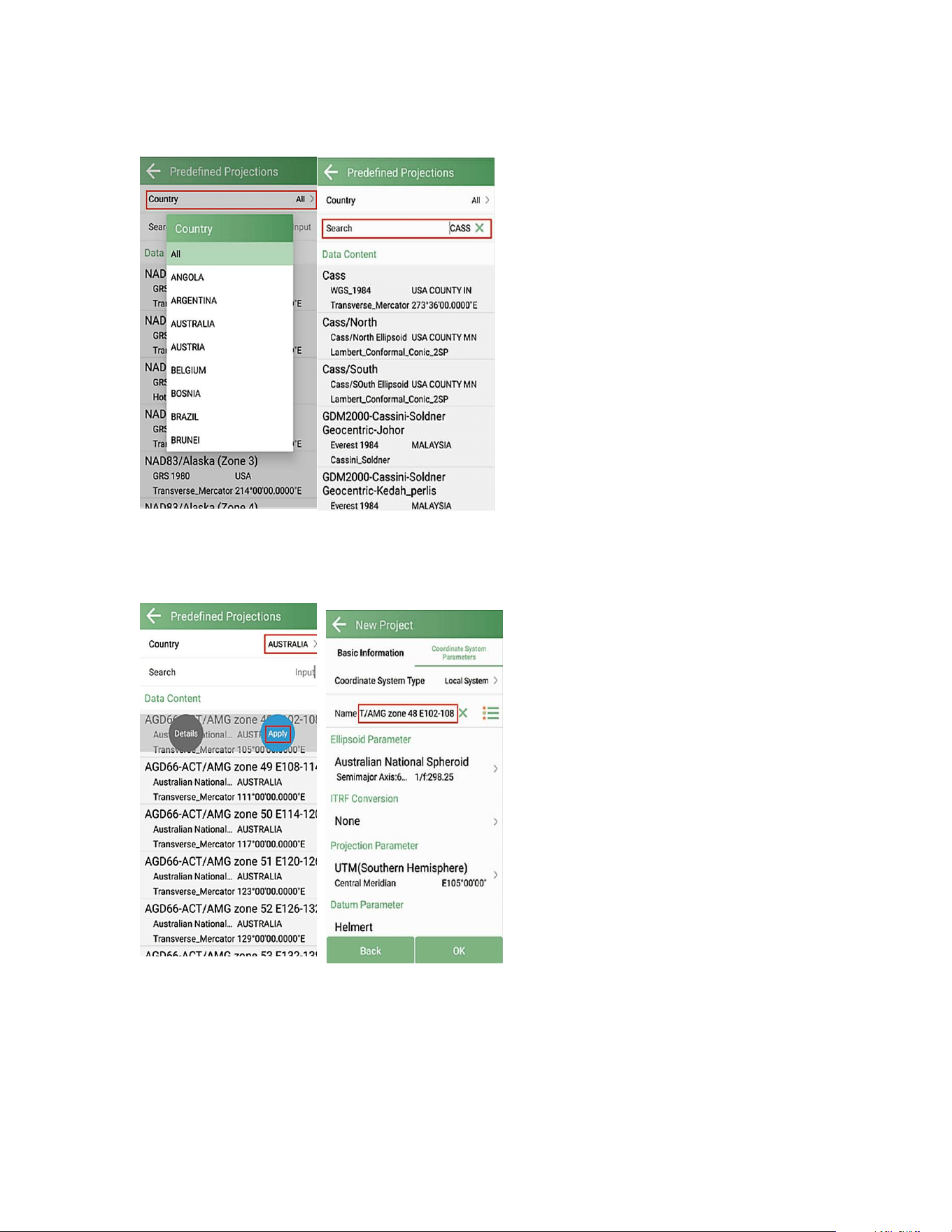
3. Click Country to select the country name or enter a keyword in Search to find it.
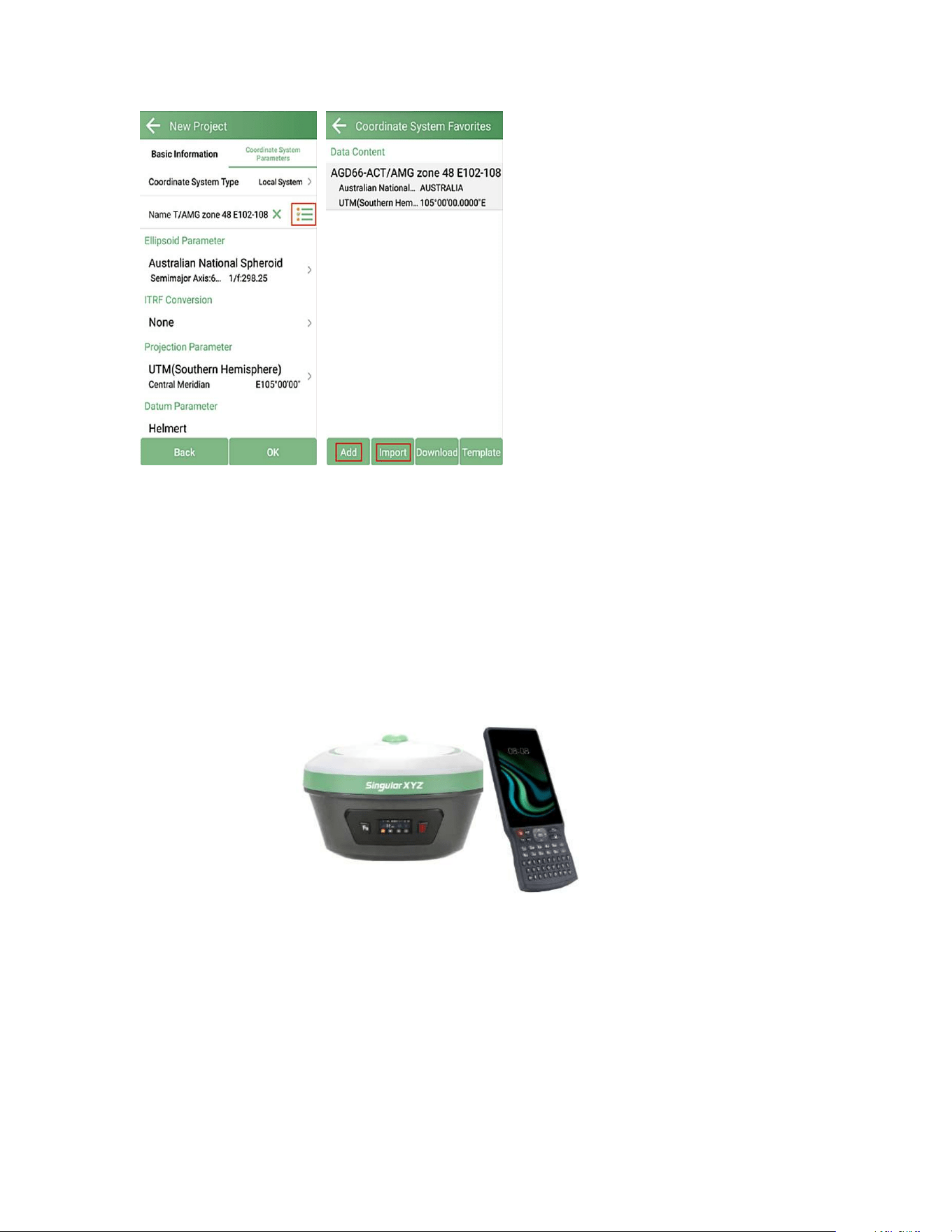
4. After locating the required coordinate system, click Apply to add it to coordinate
system parameters, click OK to apply it to the current project.
If you can not find the required coordinated system in Predefined Projections, you
can click Add or Import to create new coordinate system
12
2.3 Device connection
2.3.1 NFC connection
The Xbase GNSS Receiver is equipped with an NFC module, users can easily connect
the Xbase receiver to the data collector with just one touch, as shown in the figure
below.
NFC Connection
13
2.3.2 Bluetooth connection
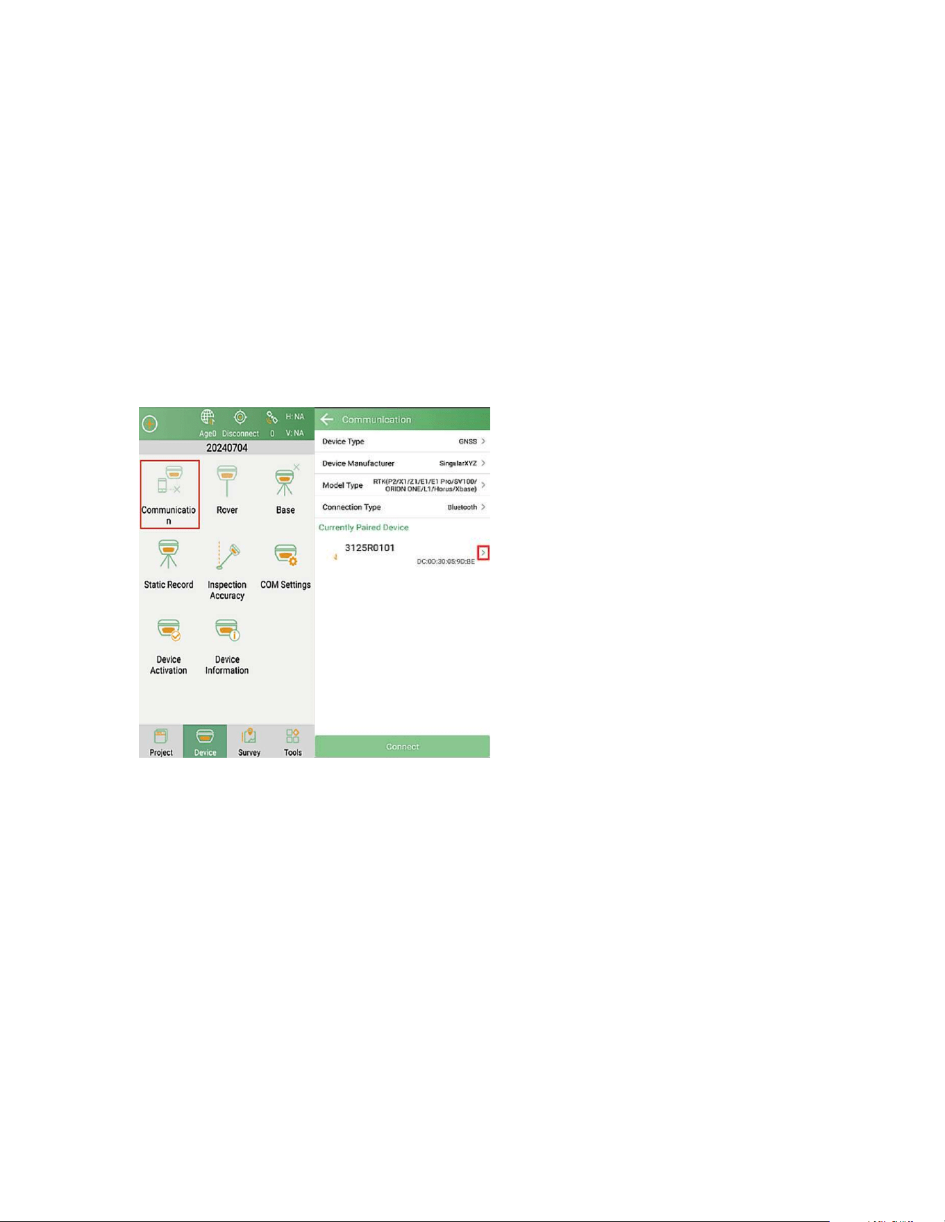
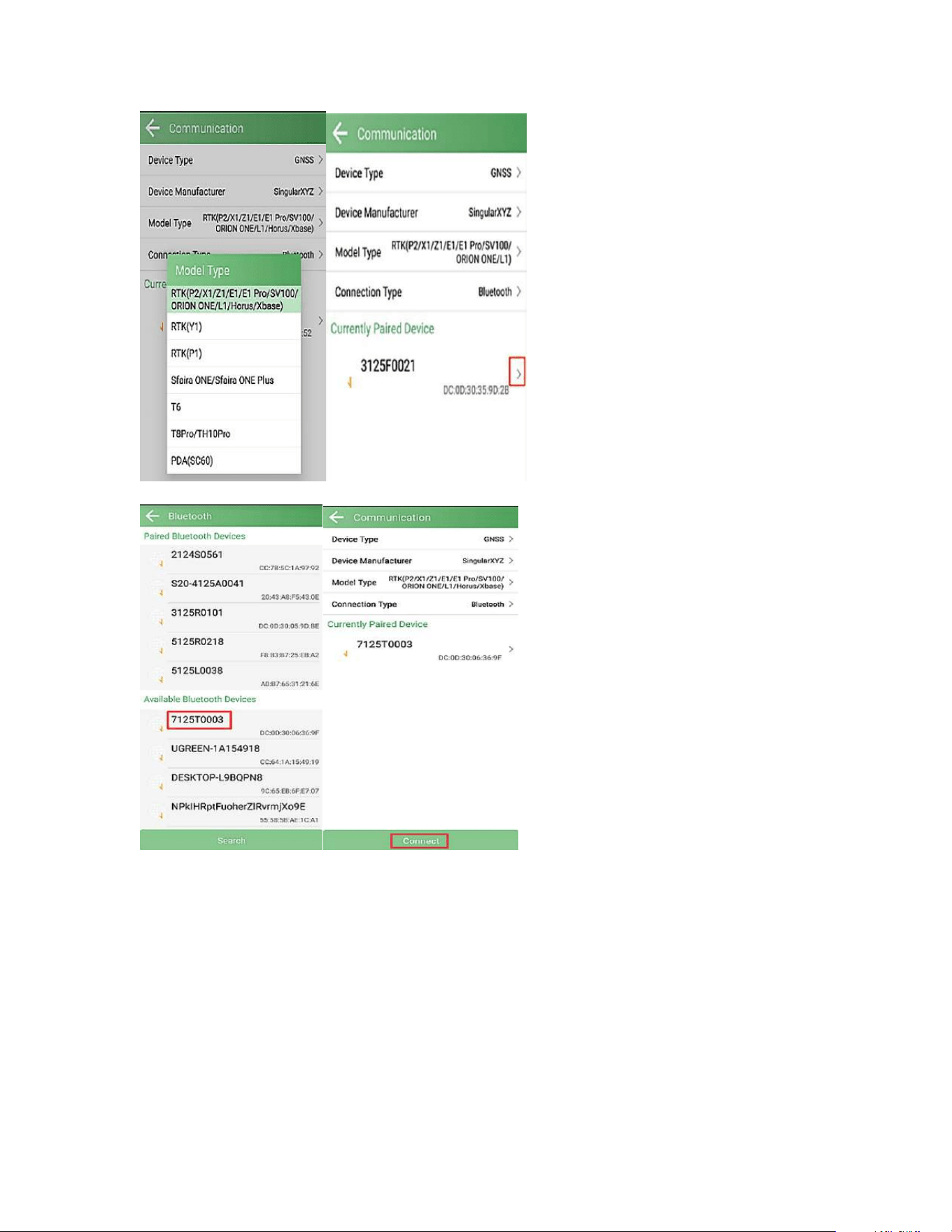
After creating a new project, switch to Device interface, click Communication. Select
the corresponding parameters according to the following requirements.
Device Type: GNSS
Device Manufacturer: SingularXYZ
Model Type: RTK (P2/X1/Z1/E1/ E1 Pro/SV100/ORION ONE/L1/Horus/Xbase)
Connection Type: Bluetooth
Ensure the Bluetooth is enabled on the data collector. Click Current Paired Devices
below to find the SN of the Xbase receiver. Click Connect
14
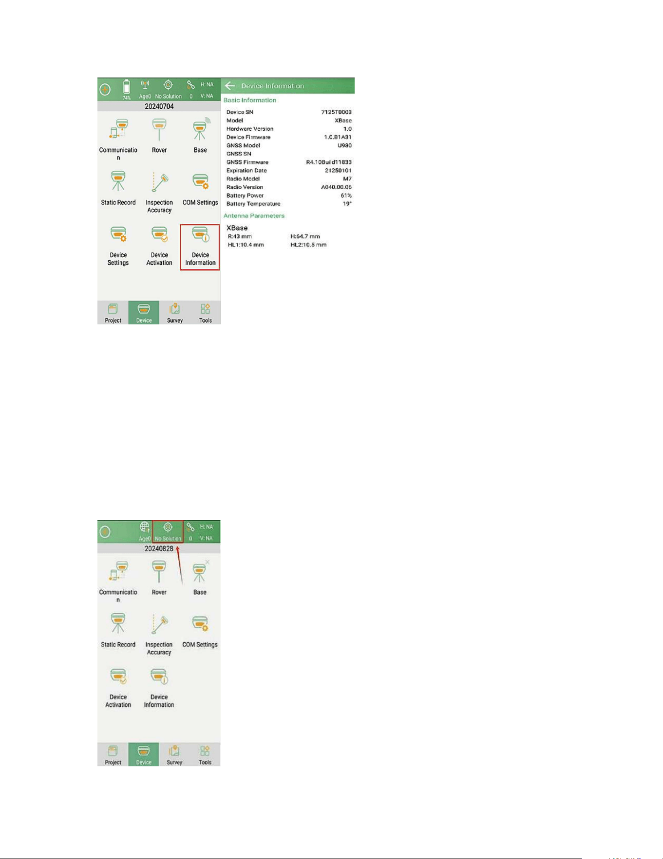
After connecting Xbase receiver, you can check the information of the receiver (such
as firmware version) in Device Information.
15
Troubleshooting
After connecting to the receiver, if <No Data> is displayed in the top status bar, it
may indicate that the<Model Type> does not match the connected receiver.
Please go back to communication interface and verify the model type, switch to
<RTK(P2/X1/Z1/E1/E1 Pro/SV100/ORION-ONE/L1)> and reconnect the device.
If <No Solution> is displayed in the top status bar, it means you are indoors without
sufficient satellite signals. Please go outdoors for satellite searching.
16
Tip
:
If you fail to connect with receiver through SingularPad, you can follow the prompts to enter the
system Bluetooth settings interface of the PDA/data collector to ensure that the Bluetooth pairing is
successful.
Sometimes you need to cancel the device Bluetooth pairing, restart the receiver or SingularPad software
and pair again.
2.4 Concepts About RTK
2.4.1 Overview
Real-Time Kinematic (RTK) is a GNSS positioning technique used to improve the
accuracy of a standalone GNSS receiver.
Traditional GNSS receivers, like the one in a smartphone, could only determine the
position with 2–4 meters (7– 13 feet) accuracy. RTK can give you centimeter
accuracy.
GNSS receivers measure how long it takes for a signal to travel from a satellite to the
receiver. Transmitted signals travel through the ionosphere and atmosphere and are
slowed down and affected on the way. For example, travel time on a cloudy day and
in clear sky conditions would be different. That is why it is difficult for a standalone
receiver to precisely determine its position. RTK is a technology that solves this
issue.
2.4.2 High-Precision Real-Time Positioning
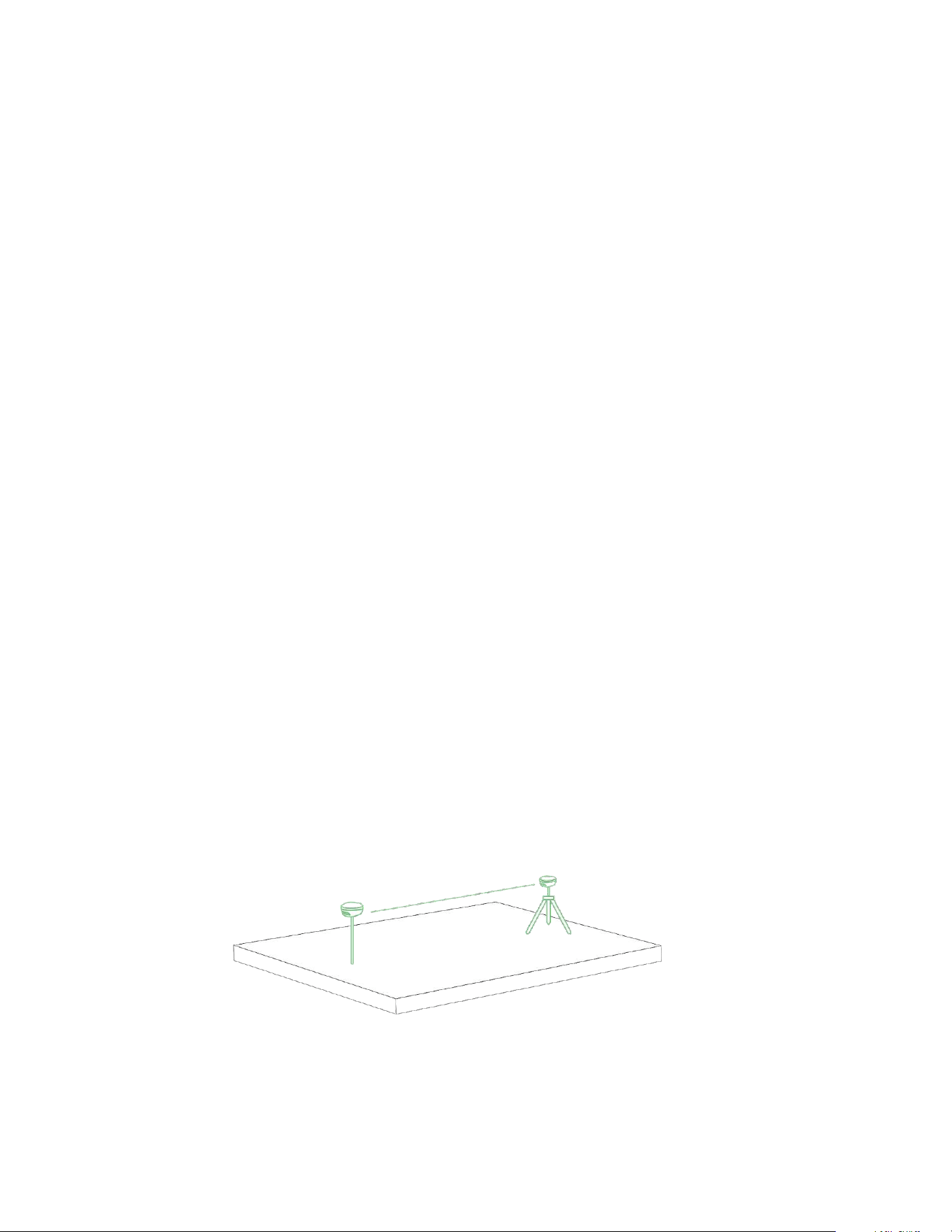
Two receivers are used in RTK. One of them is stationary, another moves freely. They
are called base station and rover.
The base is installed in a fixed location and send correction data to a moving
receiver. Rover uses that data to achieve centimeter precise position. Any number of
17
rovers can connect to one base if their input settings are compatible to the base’s
output.
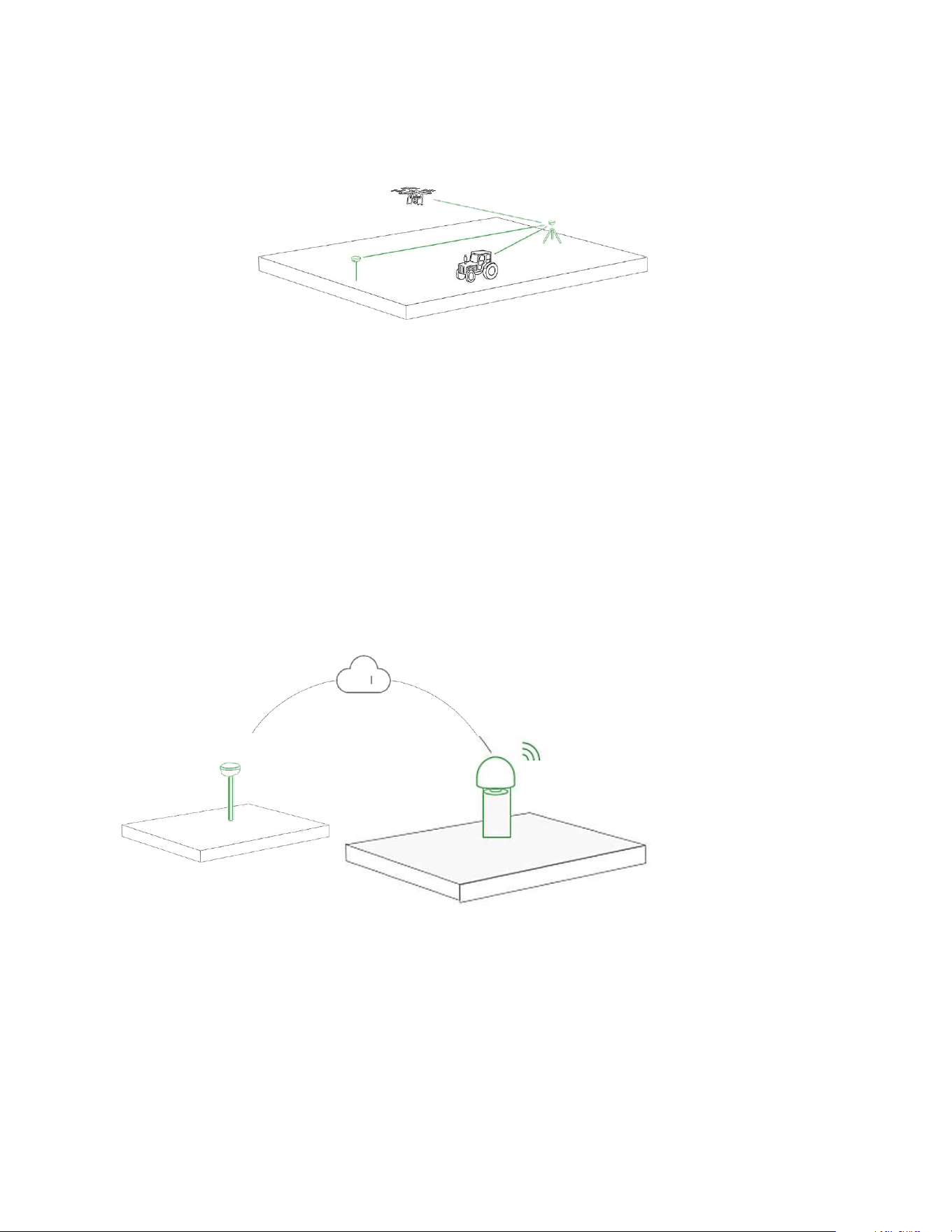
2.4.3 Corrections over NTRIP
A dedicated local base station is not always required for RTK operation. Usually,
there are local services that share base corrections over the Internet. This
technology is called NTRIP. NTRIP is a good option for areas with strong 3G/LTE
coverage and a vast network of NTRIP bases nearby. In other cases, using the second
receiver as a local base station has two advantages:
•Autonomy in remote areas as there’s no need in the Internet connection;
• Independence from local providers, no additional fees by NTRIP service.

18
2.5 Quick Setup Guide
With the help of this section, you can easily configure your Xbase and achieve
accurate positioning for your subsequent tasks. This chapter introduces three work
modes, allowing you to select the most suitable operating mode for your working
conditions and accuracy requirements.
Work
Mode
Use Conditions
Accuracy
Radio
Mode
-Two GPS RTK units (base and
rover) required
Centimeter
level
Network/
GSM Mode
- Two GPS RTK units (base and
rover) required
- Network required
- Ntrip Caster Platform required
Centimeter
level
PDA
CORS
Mode
- Network required
- RTK correction service
subscription / CORS account
needed
Centimeter
level
PPP Mode
No network or RTK correction
service needed
10 - 20 cm
SBAS
Mode
- No network or RTK correction
service needed
- SBAS coverage required
Submeter
level
Static
Mode
≥3 GNSS units required for stable
triangulation network adjustment
Millimeter
level
Note: The cost and coverage area of the CORS service may vary by country and
region depending on your local service provider

19
2.5.1 Internal Radio Mode
2.5.1.1 Internal Radio Base
During configuration, you need to connect your PDA device or data collector to the
base.
When working as a Base station, SingularPad supports transmitting the correction
data in Internal Radio mode.
Internal Radio: This mode uses internal radio to transmit the correction data from
Base to Rover. You need to set Base and Rover with the same protocol and frequency.
• Protocol: Supports CSS, TRIMTALK, TRIMMK3, TT450S, TRANSEOT and SATEL.
• Frequency: select a channel or customize a frequency, the range of frequency is
410-470 MHz
• Baud rate: 4800,9600,11000,19200,115200
• Power: High and low (low power reduces the transmission range)
TIP - Condition of the base station setup
Ideal Environment:
· Clear outdoor sky view, free
from obstructions.
· Place GPS and radio antennas
as high as possible to reduce
signal interference and
maximize communication range.
Avoid:
· Obstacles: buildings, vehicles,
towers, trees, etc.
· Interference: high-power radar,
TV, cellular towers, power lines or
electrical facilities
The following steps give an example of how to configure internal radio base mode.
NOTE: Set Internal Radio Work Mode: Connect the whip antenna to both your base station and rover.
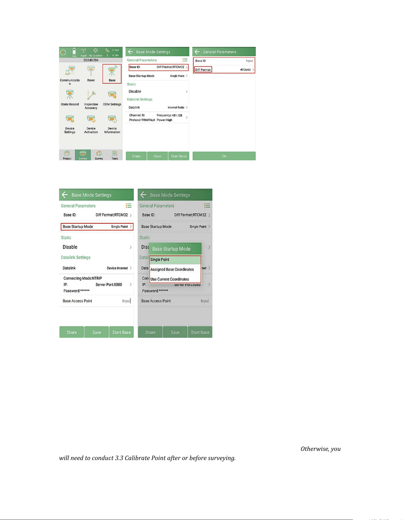
1.Go to Device >> Base. Set Base ID and choose the Diff Format.
20
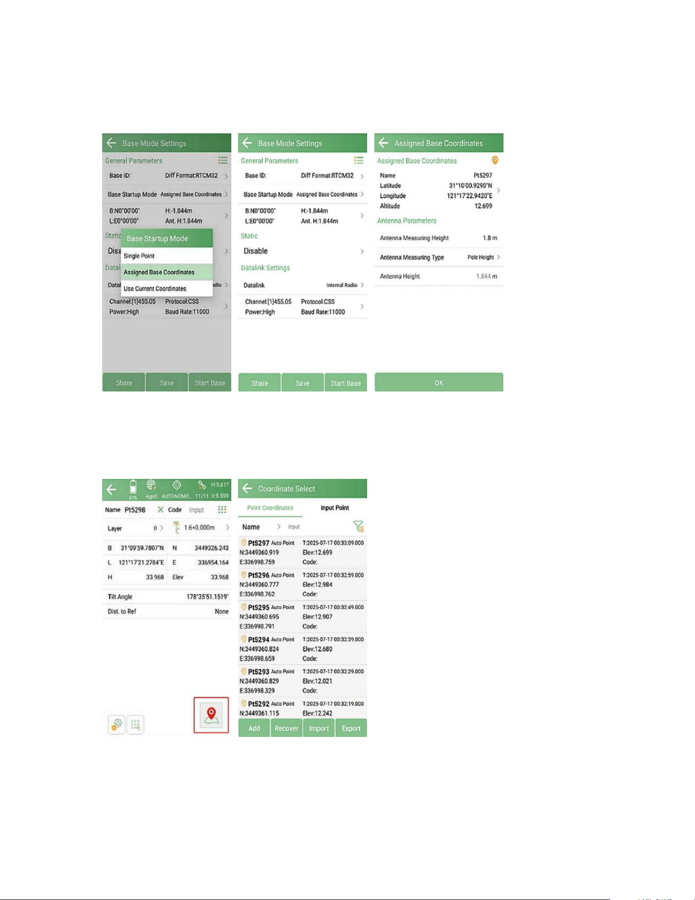
2.Click Base Startup Mode to select from the following options.
Single Point: Start the base station at unknown coordinates
Assigned Base Coordinates: Start the base station at known coordinates, and you
need to enter the latitude, longitude and the height
Use Current Coordinates: Automatically start the base station at the current
coordinates.
NOTE: For the best RTK accuracy, it is recommended to set up the base station at a known point. Select
Base Startup Mode as Assigned Base Coordinates and input the known point coordinates. Make sure the
current coordinates of the receiver are within 50 meters of the known point coordinates.. Otherwise, you
will need to conduct 3.3 Calibrate Point after or before surveying.
21
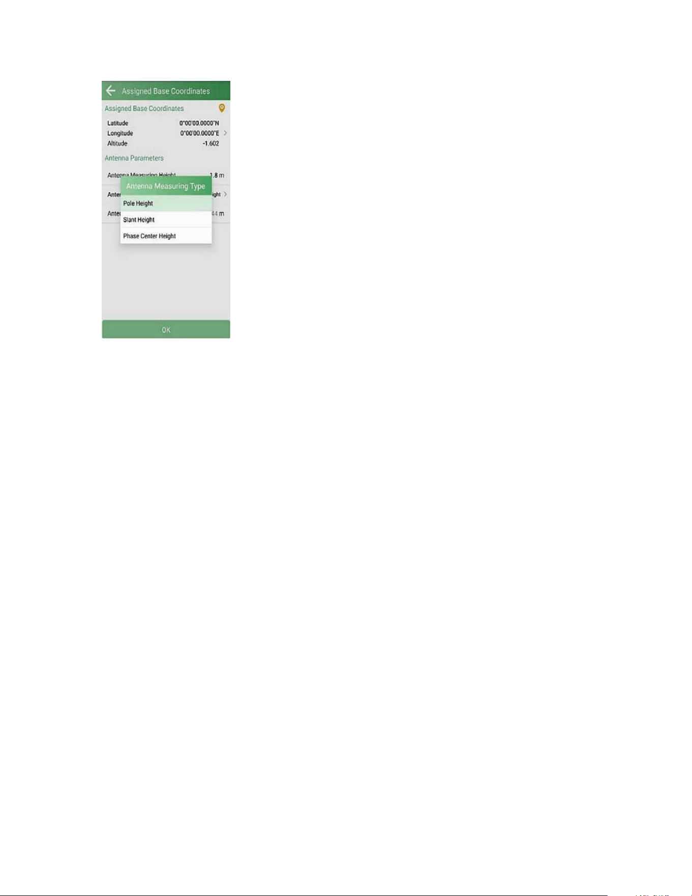
Typically, select Base Startup Mode as Assigned Base Coordinates and start the base
station at known coordinates.
You can assign the coordinates from point database (input points/measured points)
or click the survey icon to measure the current base location directly. Always use the
same coordinates when starting base at the same location.
After setting the base coordinates, set the Antenna Parameters for accurate
elevation. Click to select Antenna Measuring Type, there are three main types:
22
Pole Height: Pole height is the vertical height from the receiver’s bottom to the
ground point. If you are using a range pole with a bipod for base set-up, you can fill
the pole scale reading as the software Antenna Measurement Height when the
pole is perpendicular.
Slant Height: If you are using a tripod to set up the device, you can measure the
distance from the ground point to the antenna slant height measurement mark
(marked in the figure below). Fill the reading into the Antenna Measurement
Height, then the software will calculate the actual height.
Phase Center Height: The phase center height is the distance from the ground point
to the antenna phase center, but the antenna phase center is a virtual point of the
instrument's electromagnetic wave, and cannot be measured directly.
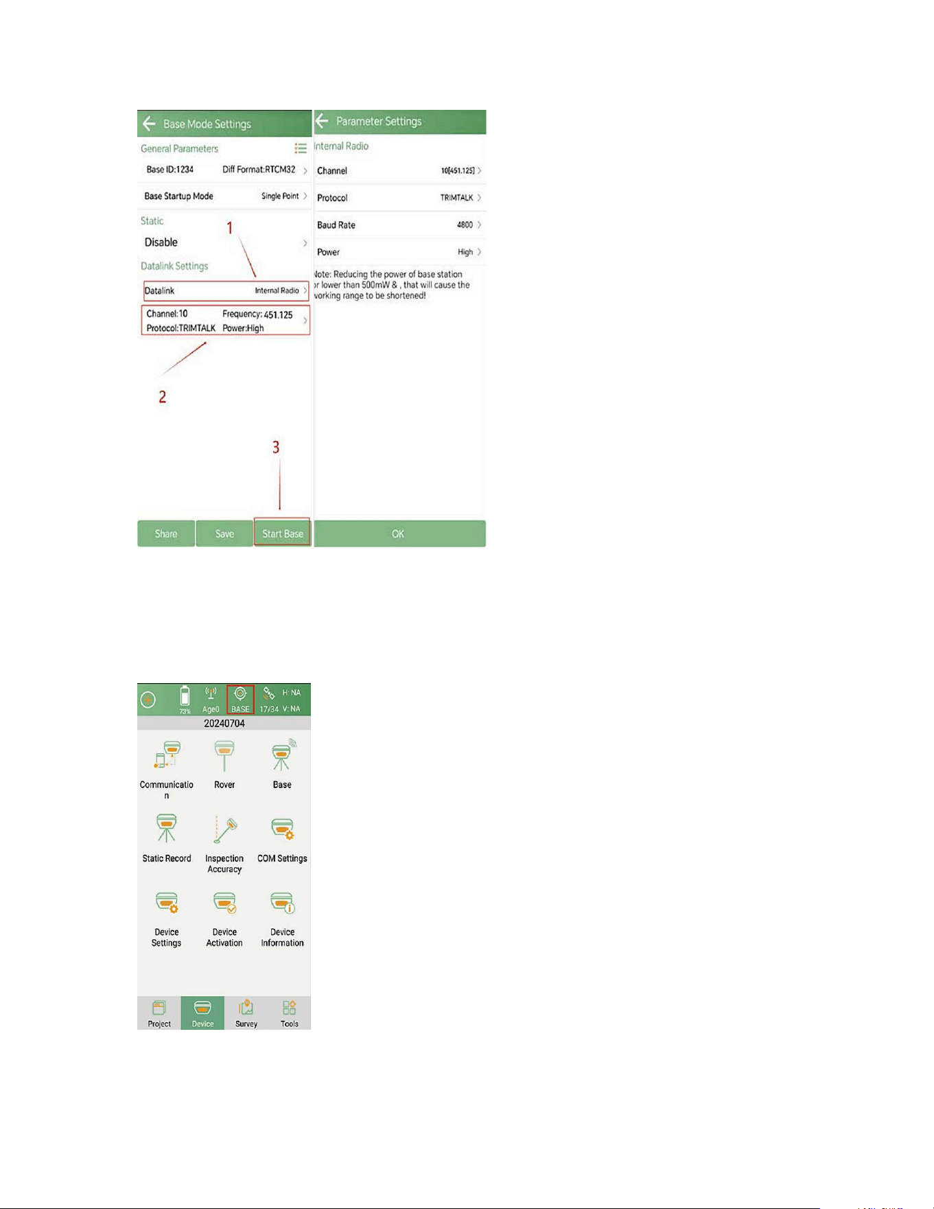
3.Set Data Link as Internal Radio. Set parameter settings, Channel,
Frequency, Protocol, Baud Rate and Power.
23
4.When the base station starts successfully, the status will show as below in
SingularPad.
NOTE: After configuring base station settings, please disconnect the base device and then search for the
SN of the rover to connect and configure the rover device. Select the same protocol and frequency as the
24
base station.
2.5.1.2 Internal Radio Rover
The following steps give an example of how to configure the internal radio rover
mode.
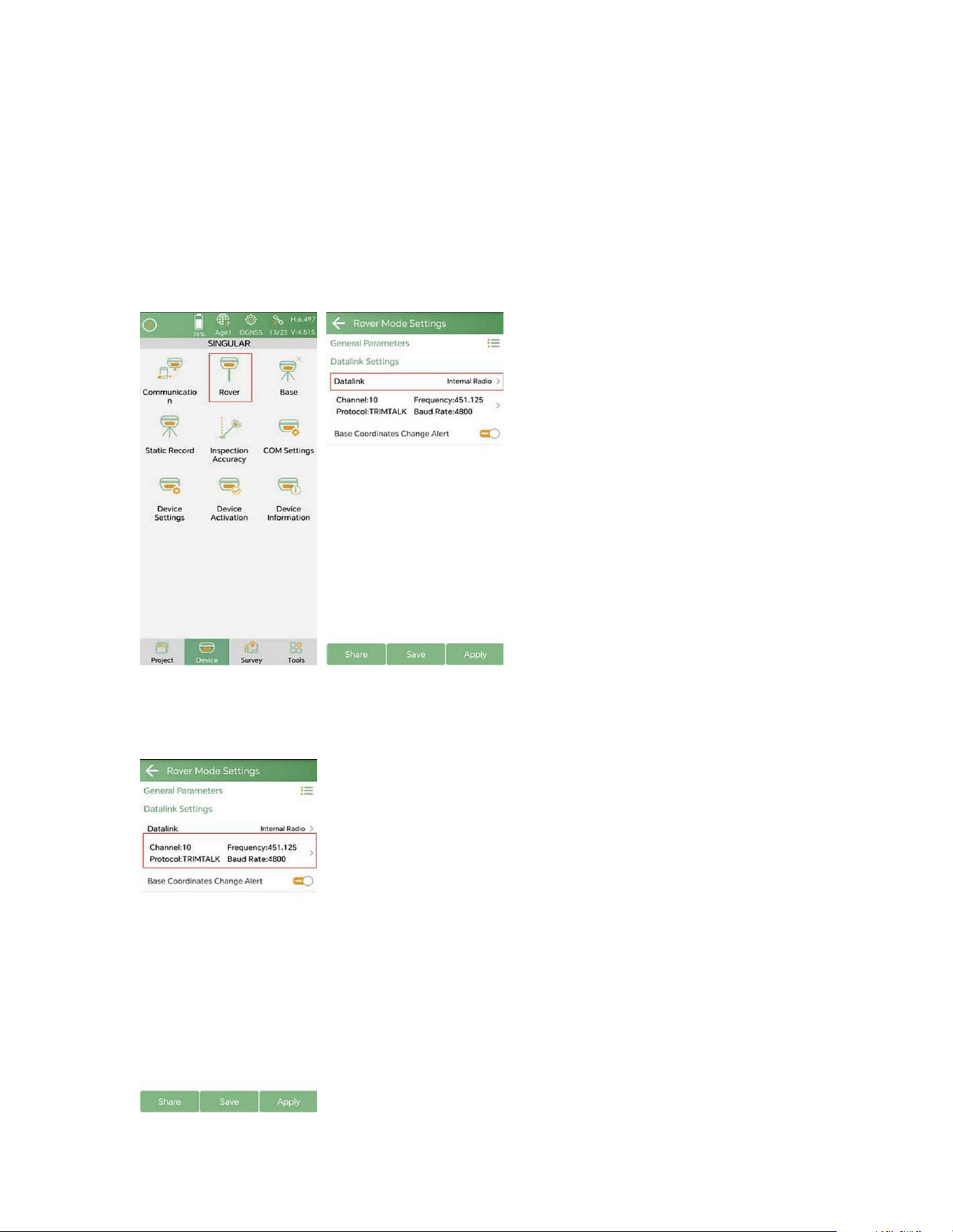
1. Go to Device >> Rover. Set Data Link as Internal Radio.
2. Parameter setting: Set channel, Frequency and Protocol the same as the base
station
25
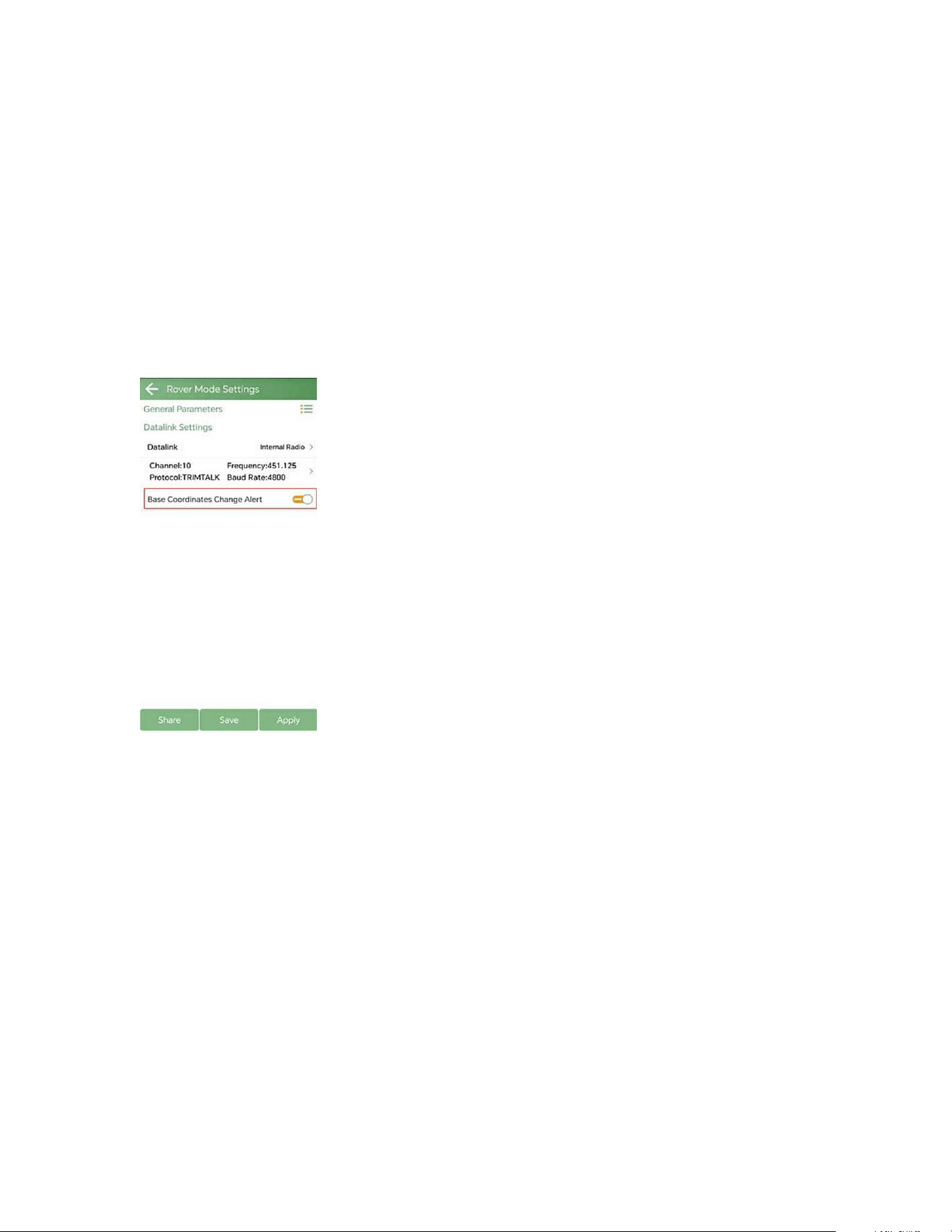
3. Base Coordinates Change Alert: SingularPad will alert when the base station
coordinates change while you are working. This may be because the rover is
mistakenly connected to another base station or the base station has been moved.
4. Click Apply to start the rover mode.
After completing the configuration, please check the RTK status in the top status bar.
Once the status changes to "FIXED" and the differential delay “Ageˮ is within the
range of 1-2 seconds, you have obtained reliable centimeter-level RTK positioning.
Now you can proceed to 3.2 Point Survey to start surveying.
2.5.2 Network Mode
In addition to radio-based RTK correction transmission, the Xbase also supports
network-based modes.
You can choose from the following configuration options depending on your
working environment and available resources.
2.5.2.1 Internal GSM Base Mode
Network Base Options:
26
Local RTK Service/CORS: You can subscribe to a local CORS/RTK Service account to
get RTK corrections. Typically, the account includes IP address, port, mountpoint,
username, and password for accessing correction data.
Internal GSM Base Mode (XBASE): Set up the receiver as an internal GSM base to
broadcast RTK corrections via a network connection.
NOTE: A valid SIM card must be inserted into the receiver. You will also need a
NTRIP caster platform to distribute correction data from the base to the rover.
When working as a base, SingularPad supports broadcasting the correction data in
Device internet Mode.
Device Internet: This mode uses the receiver network to transmit the correction
data from Base to Rover. Please insert a valid SIM card into your Xbase receiver.
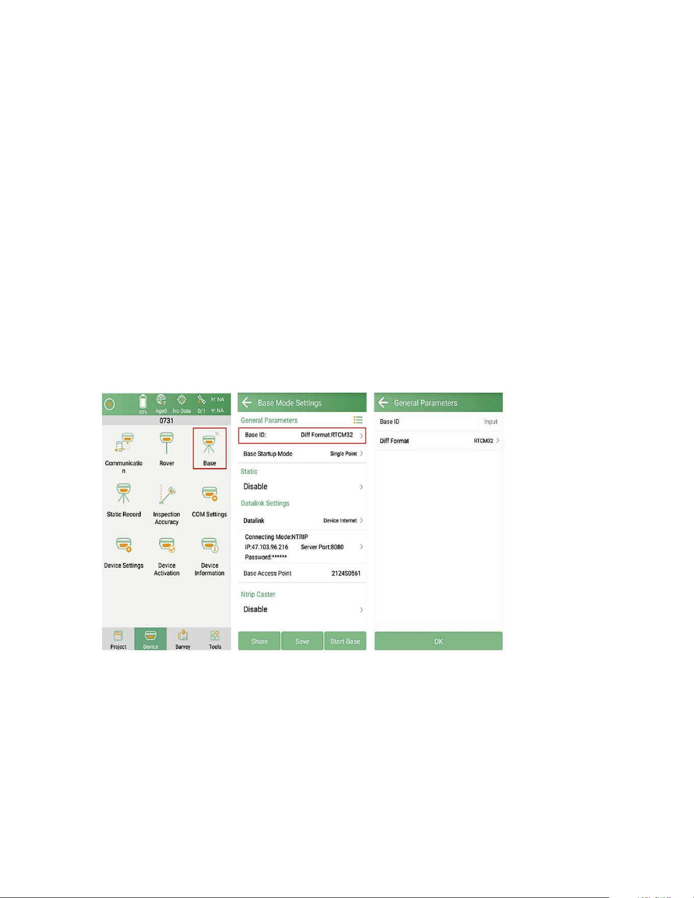
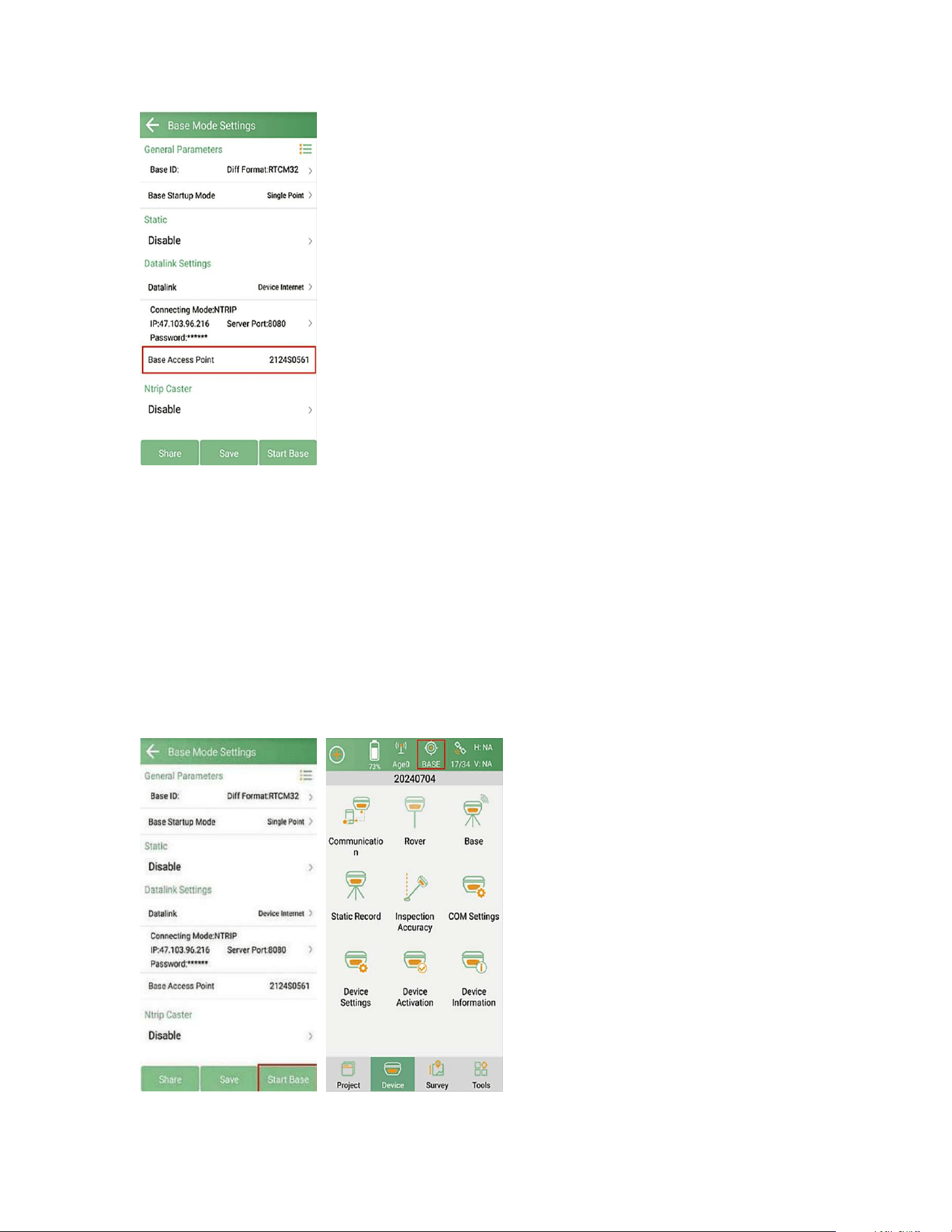
1.Go to Device >> Base. Set Base ID and choose the Diff Mode (typically RTCM32).
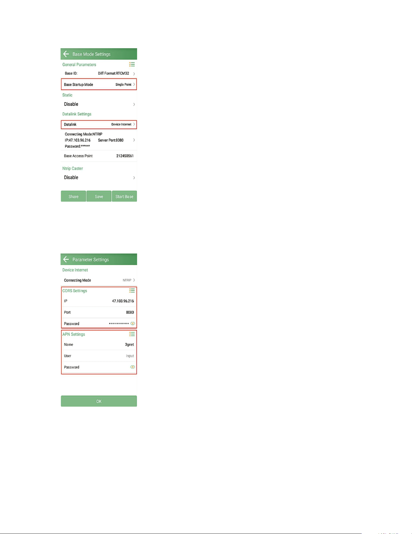
2. Set Start up Mode (please refer to chapter 2.5.1 for details). And set Data link to
the Device Internet.
27
3. Set Connecting Mode as Ntrip and input the detailed parameters: Input the IP,
Port, Password according to your Ntrip Caster platform. Input APN Settings
according to your SIM card mobile service provider.
4. Set the Base Access Point in the end, which will be the mountpoint name when
configuring RTK rover.
28
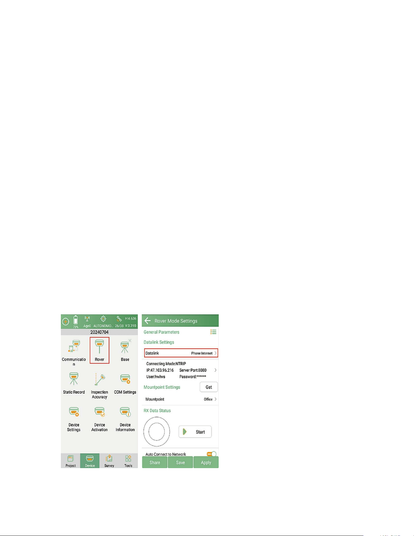
5. Click Start Base. After the base station starts successfully, its status will show in
SingularPad as below.
29
Note:
XBase receiver does not support hot swap of SIM card. Please shut down the receiver then insert the SIM
card. If you insert the SIM card when the receiver is on, please reboot the receiver.
2.5.2.2 PDA CORS Rover Mode
When working as a Network Rover, SingularPad supports receiving the correction
data in Phone internet Mode.
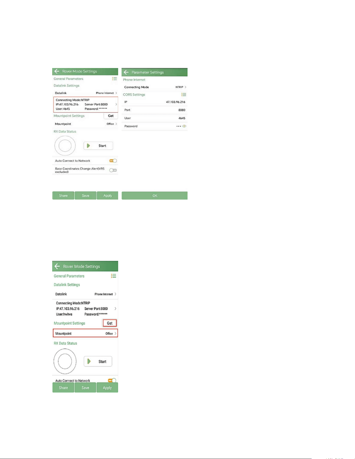
Phone Internet: This mode uses the phone internet to transmit the correction data
from Base to Rover. Please make sure the PDA device is in good network conditions,
such as 4G (SC200/SC300 data collector can obtain a 4G network signal by inserting
a SIM card), WiFi or hot spot.
1. Go to Device >> Rover. Set Data link to the Phone Internet.
30
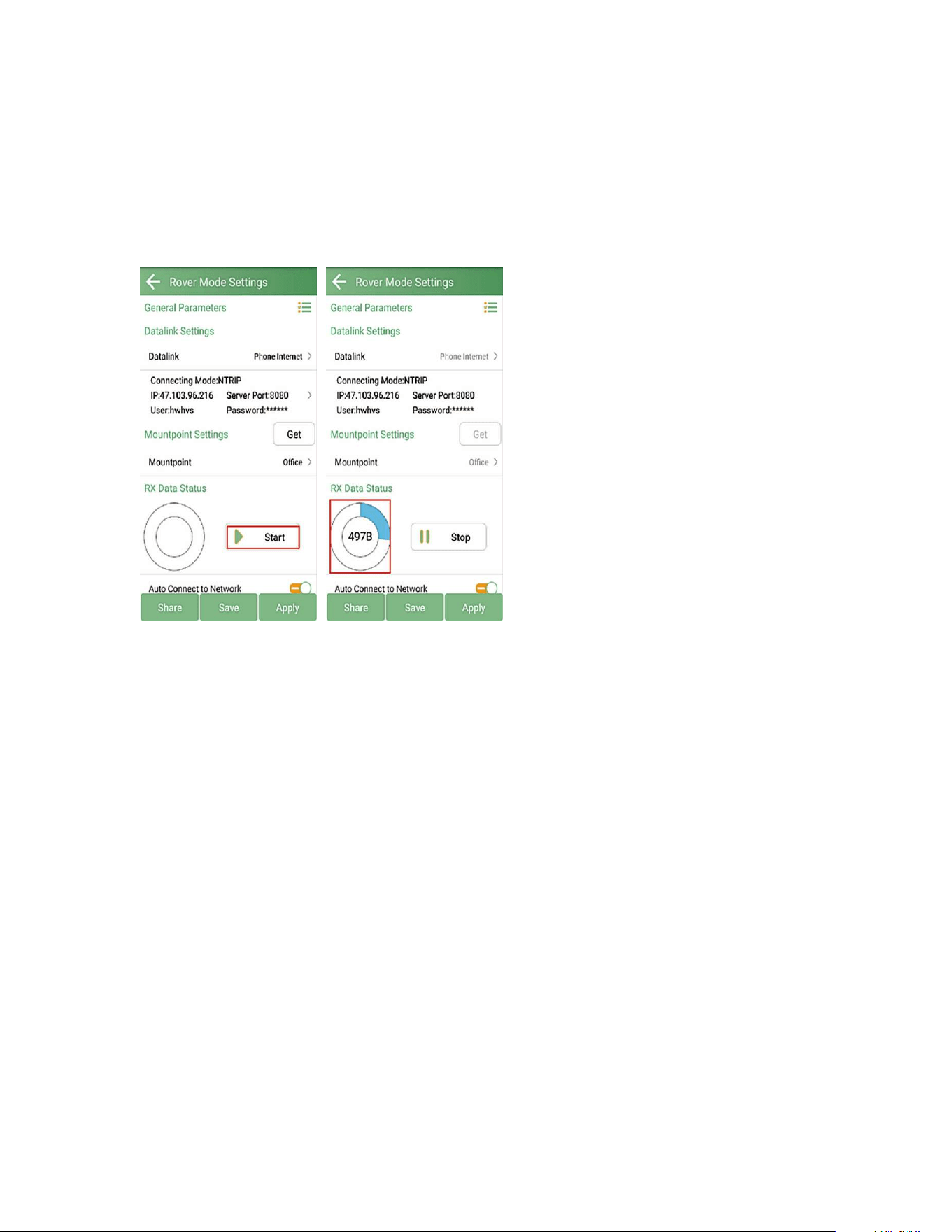
2. Set Connecting mode as NTRIP. CORS Settings: Input the server IP, Port, User and
Password in the CORS Settings.
NOTE: IP & port in the picture is only for example. Please enter your local CORS
account instead. You can purchase a third-party RTK corrections service account in
your local area to obtain an RTK FIX solution.
3.Click Get button to get the mountpoint list and choose the mountpoint.
NOTE:
31
The mountpoint shown in the figure is for demonstration purposes only. Please find out the
appropriate mount point via the website of your local NTRIP/CORS provider. Make sure that the
baseline does not exceed 50km.
4.Click Start button to receive data from CORS/RTK correction service once the
connection is established.
NOTE:
If you have clicked Start but there is no data displayed in RX Data Status, please check
the parameter information above.
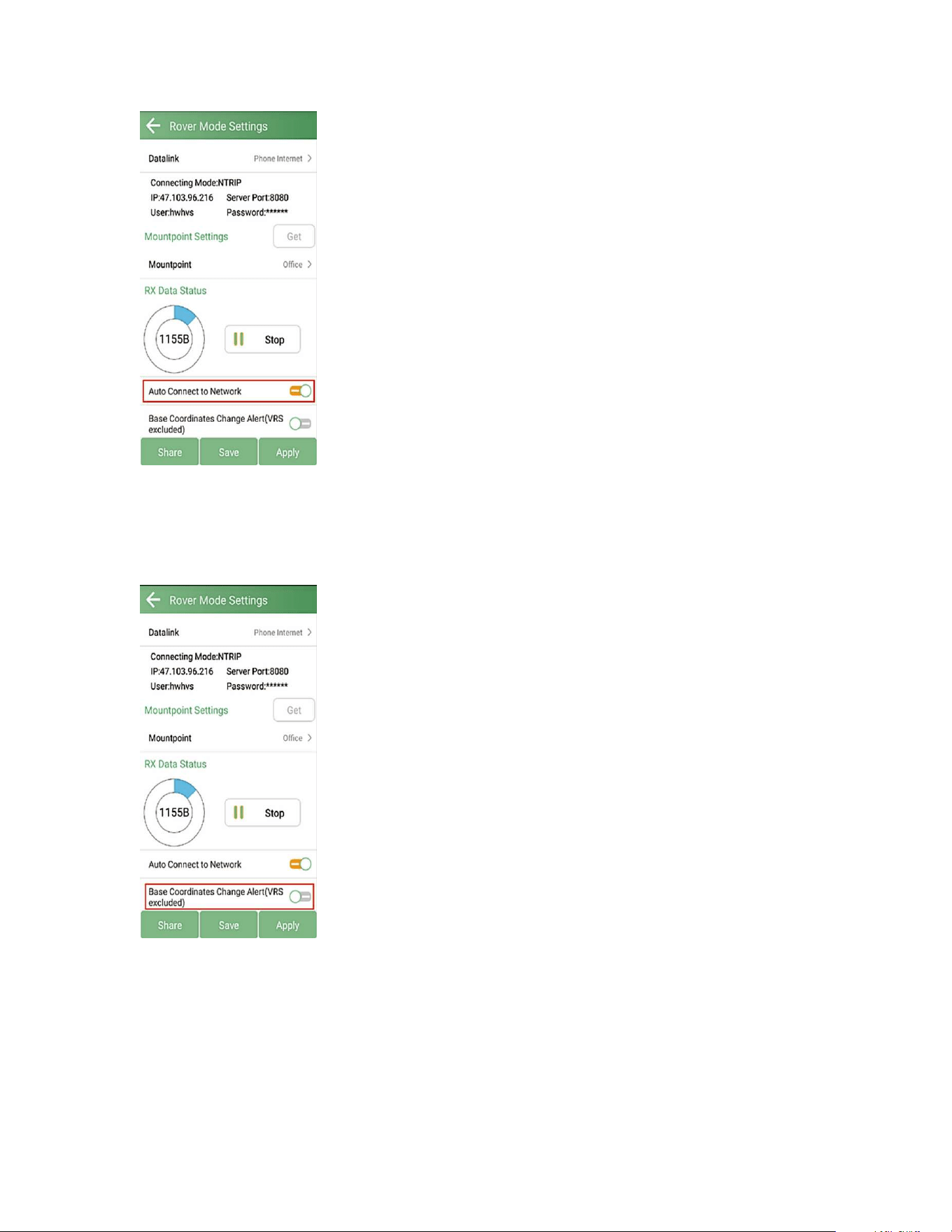
5. Auto connect to network: When this option is opened, SingularPad will connect to
the network automatically so that users do not need to click Start to connect to the
network.
32
6. Base Coordinates Change Alert: SingularPad will alert the user if correction data is
received from different base station. When you are using VRS, it is recommended to
disable this option.
7. Click Apply to start the Rover mode.
After completing the configuration, please check the RTK status in the top status bar.
Once the status changes to "FIXED" and the differential delay “Ageˮ is within the
range of 1-2 seconds, you have obtained reliable centimeter-level RTK positioning.
Now you can proceed to 3.2 Point Survey to start surveying.
33
2.5.2.3 INTERNAL GSM ROVER MODE
Network Rover Options:
PDA CORS Rover Mode: Receive RTK correction data via the mobile network of your
data collector or other Android PDA device.
NOTE:
Make sure the data collector or mobile device you are using has an active internet connection.
Internal GSM Rover Mode: Insert a SIM card into the GNSS receiver and access RTK
correction data directly through the receiver network.
When operating as a Rover, SingularPad supports receiving RTK correction data in
Device internet Mode.
Device Internet: This mode uses the receiver’s network to transmit the correction
data from Base to Rover. Please insert a valid SIM card into your XBASE receiver.
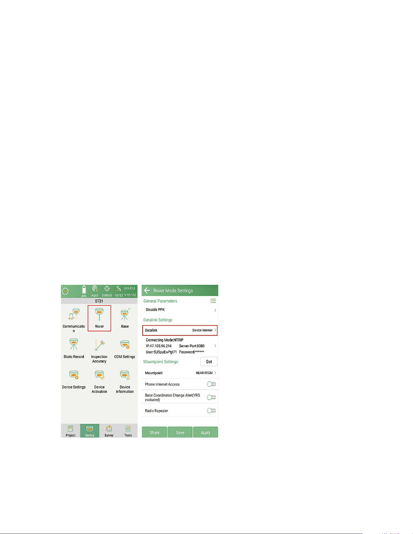
1. Go to Device >> Rover. Set Data link to the Device Internet.
2. Set Connect mode, for Xbase receiver supports NTRIP and TCP Client.
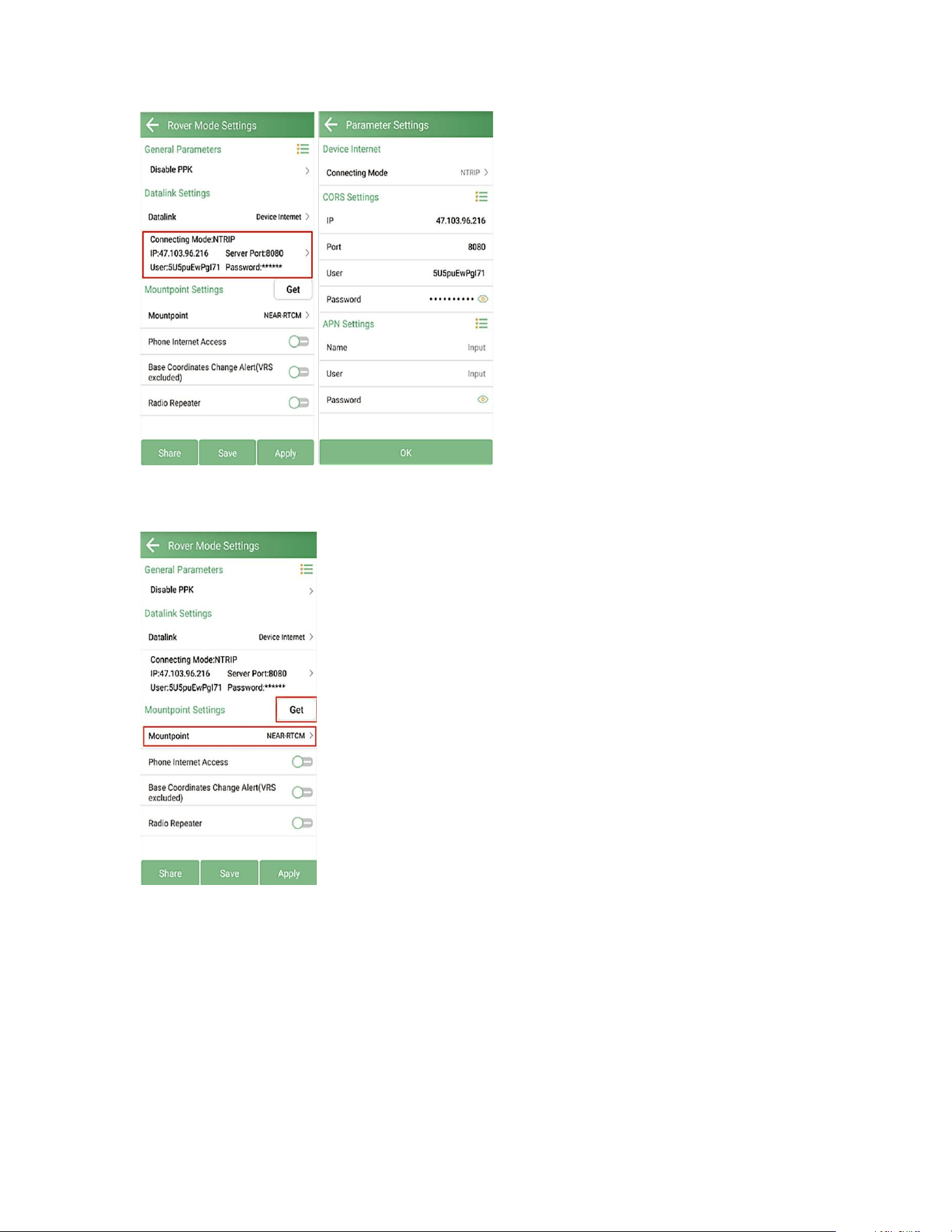
CORS Settings: Input the server IP, Port, User and Password in the CORS Settings.
34
3.Click Get to get the mount-point list and choose the mountpoint.
NOTE:
The mount point "NEAR-RTCM" shown in the figure is an example only. Please find out the appropriate
mount point via the website of your local NTRlP/CORS provider or the base name you set in internal
GSM base mode. For optimal RTK performance, it is recommended that the baseline does not exceed
50km.
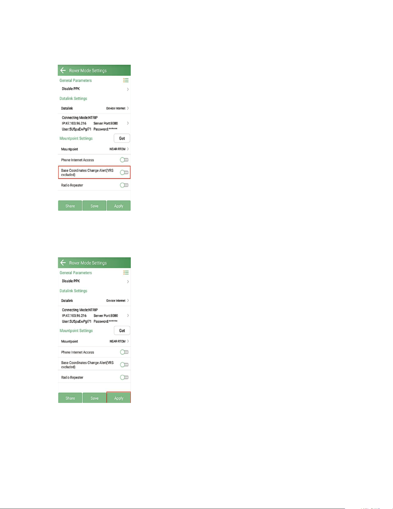
4. Base Coordinates Change Alert: SingularPad will alert when you connect with
different base station. When you are using VRS, it is recommended to disable this
35
option.
5. Click Apply to start the Rover mode
After completing the configuration, please check the RTK status in the top status bar.
Once the status changes to "FIXED" and the differential delay “ageˮ is within the
range of 1-2 seconds, you have obtained reliable centimeter-level RTK positioning.
Now you can proceed to 3.2 Point Survey to start surveying.
36
2.5.3 PPP MODE
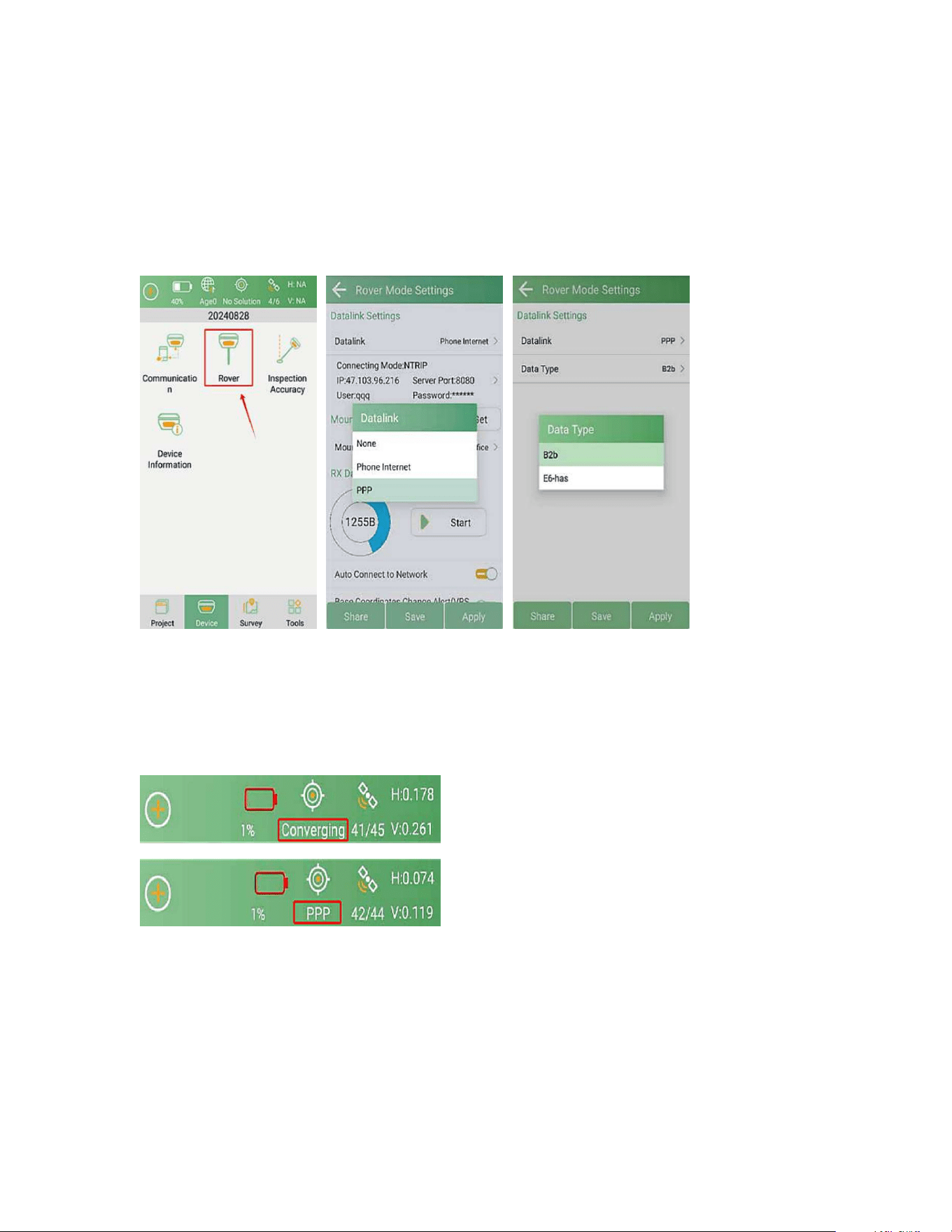
Enter Device >> Rover, select Datalink as PPP, and you can choose Data Type
between Beidou B2b and Galileo E6-has, then click Apply.
After configuration, the PPP mode will take around 10 minutes converging to typical
accuracy. You can see the positioning state in the top status bar will change and
remain in Converging for around 10 minutes. After the positioning state changes to
PPP mode, you can then conduct surveying tasks.
2.5.4 SBAS MODE
Click the satellite icon in the top status bar to enter the Position Information
interface, then click Settings. Enable SBAS and click OK.
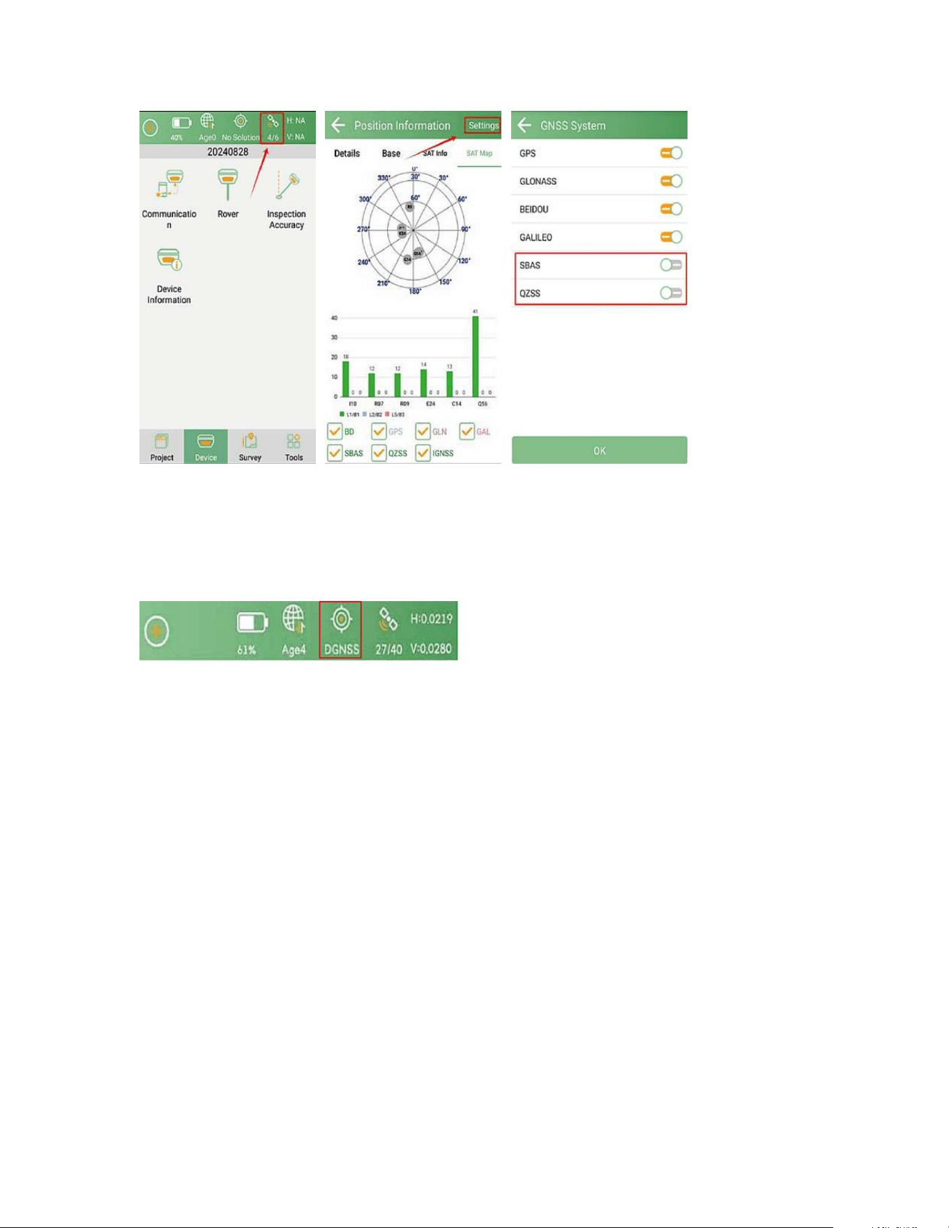
37
After configuration, you can see the positioning state in the top status bar will
change to DGNSS, now you are ready to conduct surveying tasks.
38
3 RTK SURVEY - FIELD DATA COLLECTION
This section introduces the basic survey functions of SingularPad, including Point
Survey, Calibrate Point, Localization, Tilt Survey, Point Stakeout and etc. Before
RTK survey, you need to connect to the receiver and get a fixed solution.
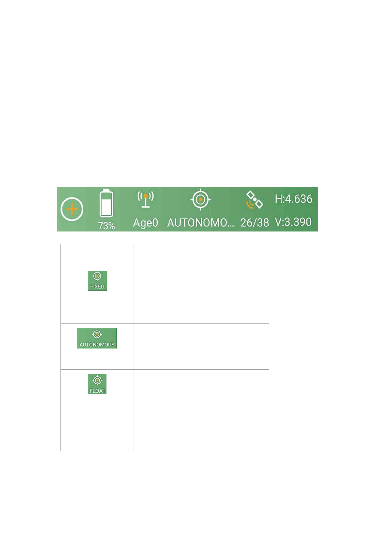
3.1 SingularPad Status Bar
After completing your Xbase RTK setup, check current RTK solution status at the
top of the SingularPad software.
RTK solution status
Description
The device is receiving RTK corrections
stably and obtaining a Fixed RTK
solution with centimeter-level
accuracy.
Single-point satellite positioning
without receiving RTK correction data.
The accuracy is around meter-level.
The device receives corrections from
the base/CORS, but due to
obstructions or magnetic field
interference the signal reception is not
very stable and the accuracy is sub-
meter level.
39
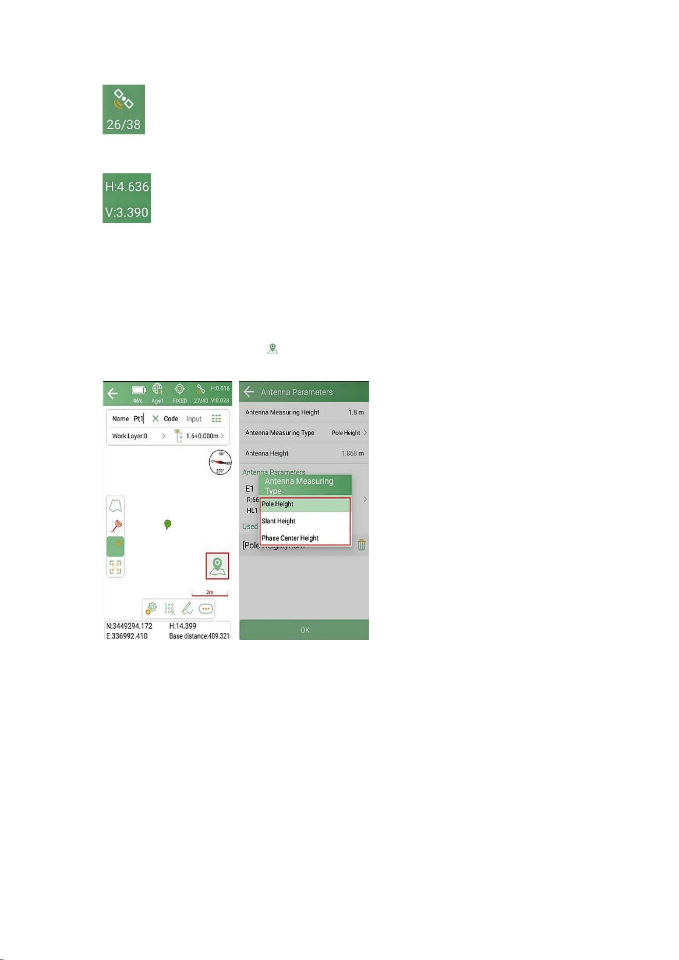
The satellite icon shows calculated satellites number/tracked satellites
number. You can click it to check satellite map and more information.
The status bar also displays HRMS and VRMS on the top of the
interface. Tap the HRMS or VRMS value to view detailed positioning
quality information.
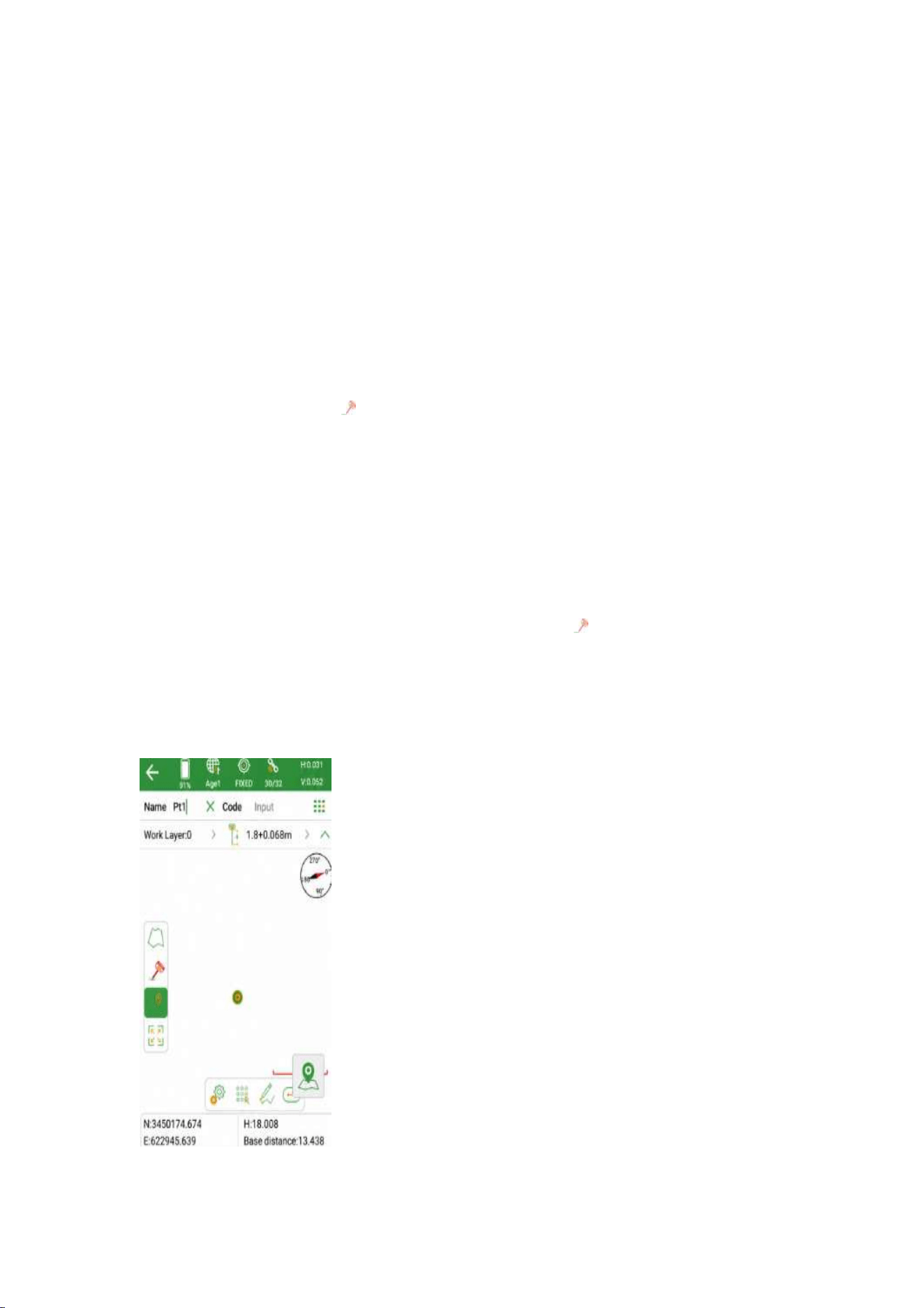
3.2 Point Survey
In the Survey interface, click Point Survey and enter point Name, Code and
Antenna height, then click to start or stop collecting data.
NOTE: Our software supports 3 antenna measuring types, please refer to chapter
2.5.1 for details.
Pole Height: Typically in rover mode, select the Antenna Measuring Type as Pole
Height and enter the height of your centering pole.
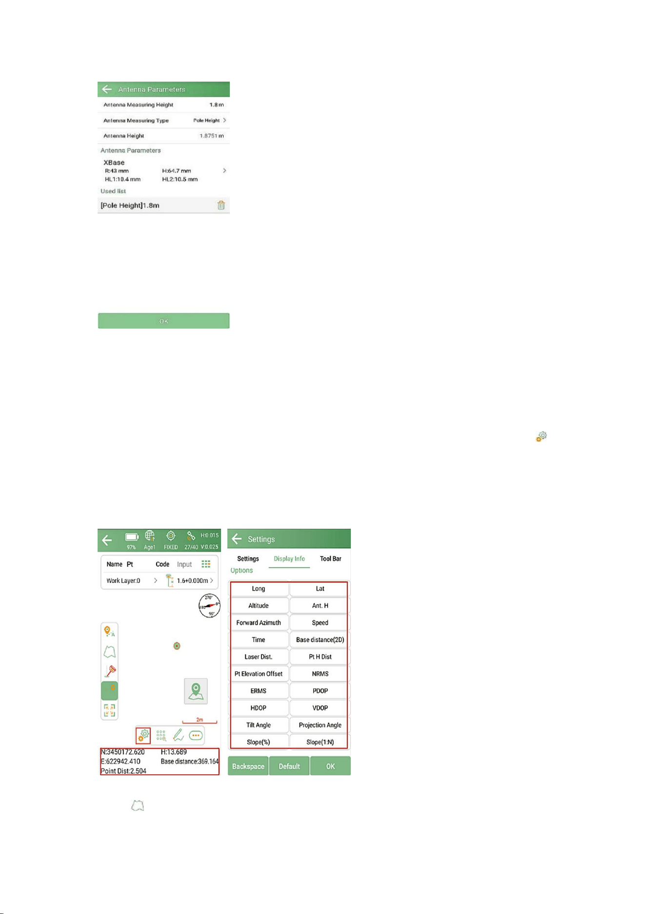
40
In the floating window of the survey interface, you can see the real-time survey
information. The default display information is N, E, H, and Base distance. Click
the floating window to customize the displayed information. You can also click
to enter the display information settings interface and customize the information
you need to display. Except default display information, SingularPad supports
Longitude, Latitude, Altitude, etc.
Click to select different map types or do map calibration. SingularPad
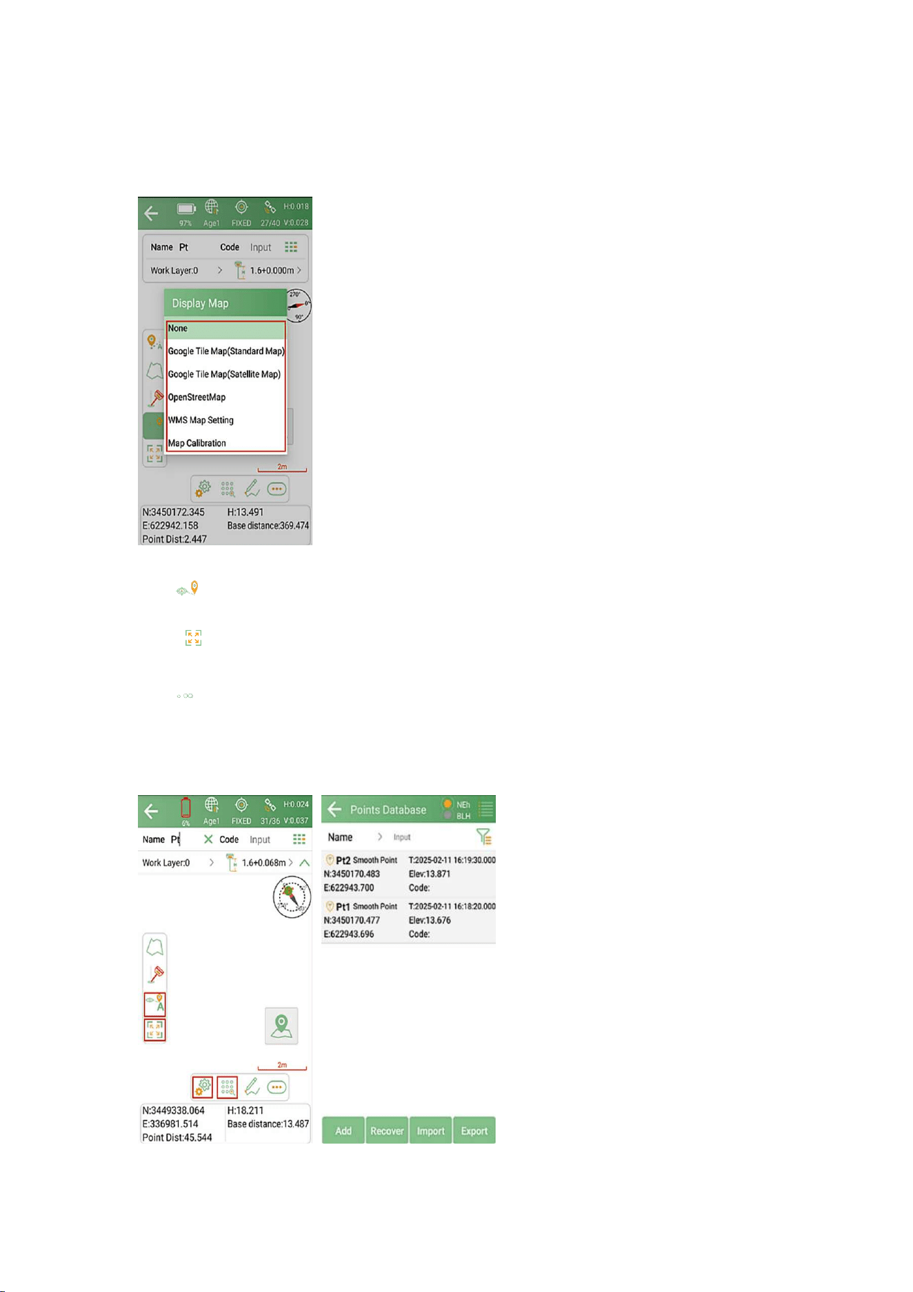
41
supports Google Map(Standard Map/Satellite Map), OpenStreetMap and WMS
Map.
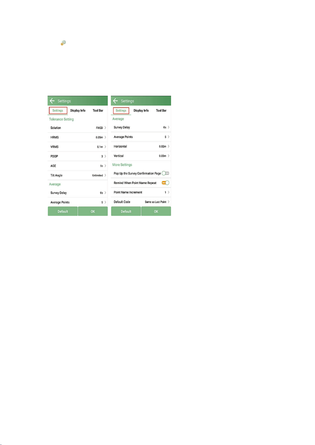
Click to center map on current position
Click to display all survey points on the interface.
Click to enter the point database. You can add, recover, import and export
data. After selecting a point, you can view the details and add notes or attach
photos.
42
Click to enter Settings interface
In Settings interface, you can modify Tolerance Setting such as solution limit,
HRMS limit, VRMS limit and etc. and modify Smooth parameters and other
Settings options.
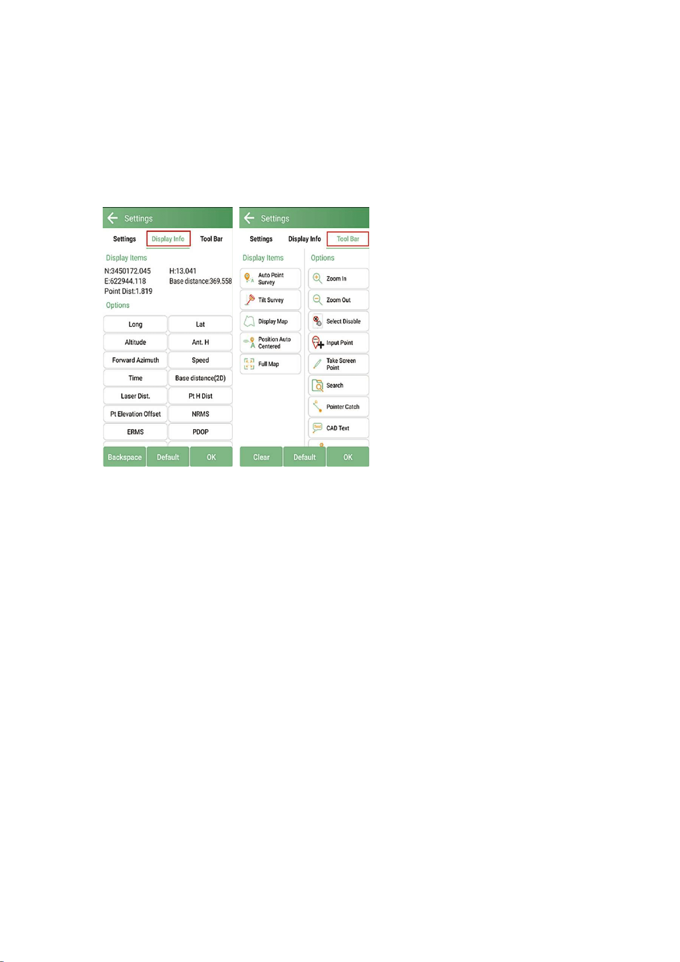
43
In Display Info interface, you can set the display information to the floating
window, such as longitude, latitude, altitude, etc.
In Tool Bar interface, you can add or delete options that displayed on the point
survey interface. You can customize the interface layout to suit your preferences.
44
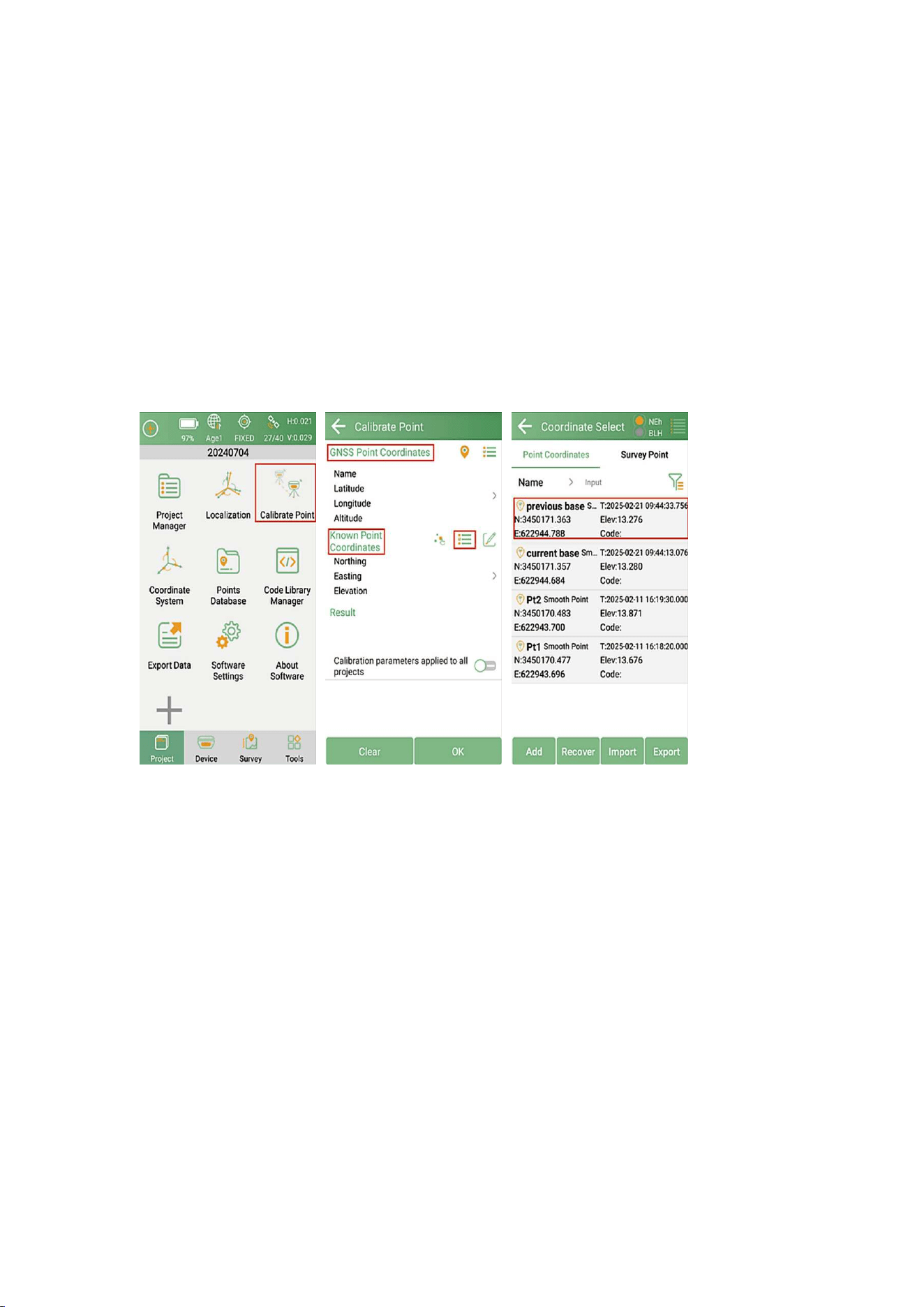
3.3 Calibrate Point
When changing the position of the base station, there will be offsets between
surveying points under different base stations. Users can use the Calibrate Point
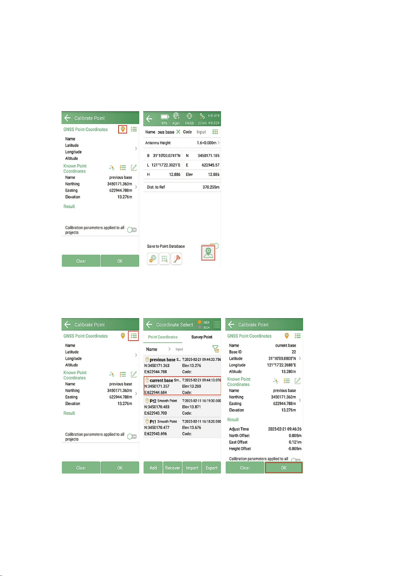
to calibrate the offset.
Go to Project > Calibrate Point. Add a point measured under the previous base
station as Known Point Coordinates, and measure the same point under current
base station as GNSS Point Coordinates.
45
For the GNSS Point Coordinates, you can click the surveying icon to measure
under the current base directly.
NOTE: Please confirm the RTK status is FIXED before performing the calibration.
Or measure the GNSS point under the current base station in advance and click to
select from the point database.
46
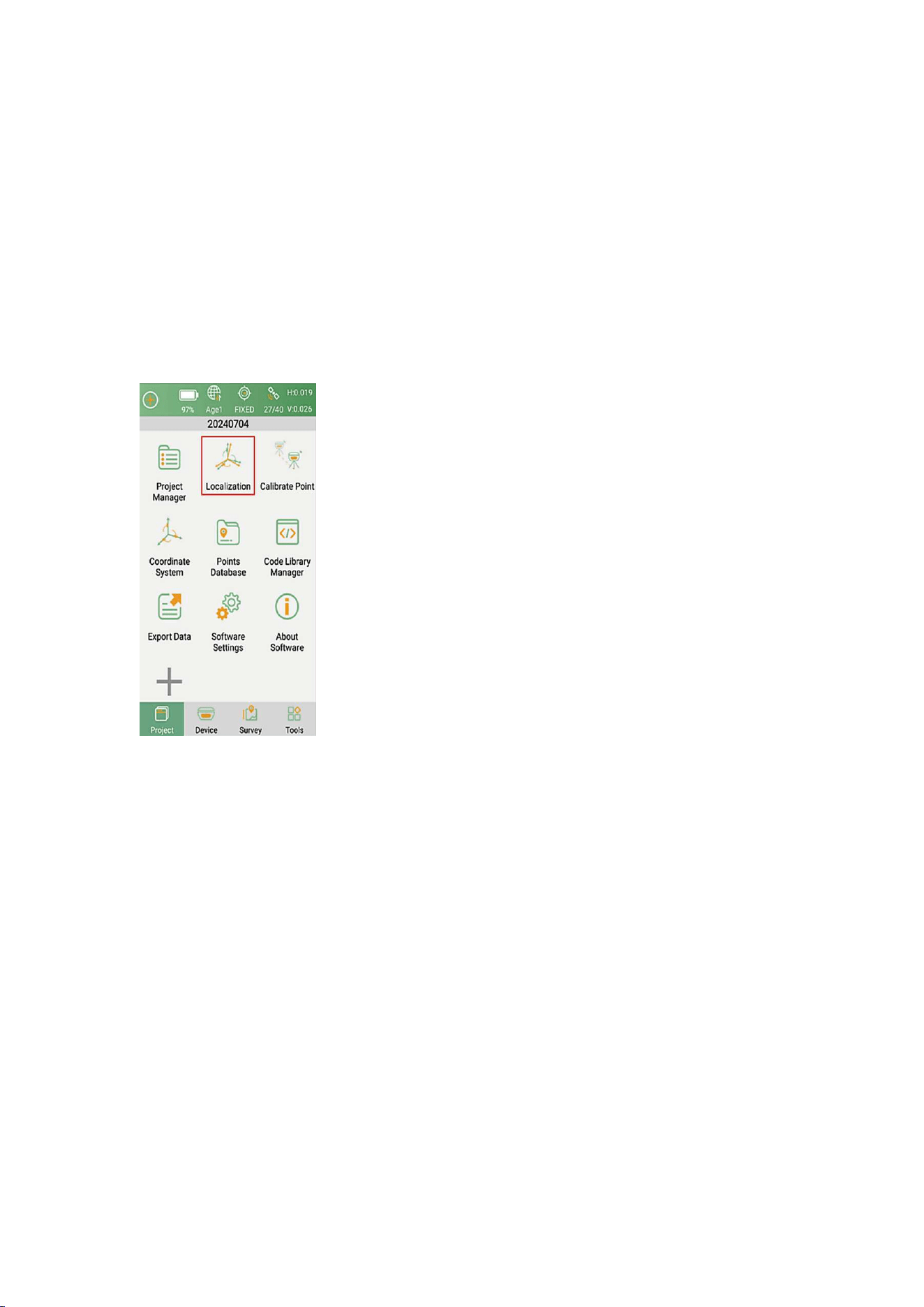
3.4 Localization
When starting a new project, if you are using the local coordinate system, you can
use Localization function to transform the geodetic coordinates system to your
local coordinate system.
Go to Project > Localization, add at least 3 pairs of points to perform
Localization.
NOTE: A pair of points are the known local coordinates and the surveying
coordinates of the same point
47
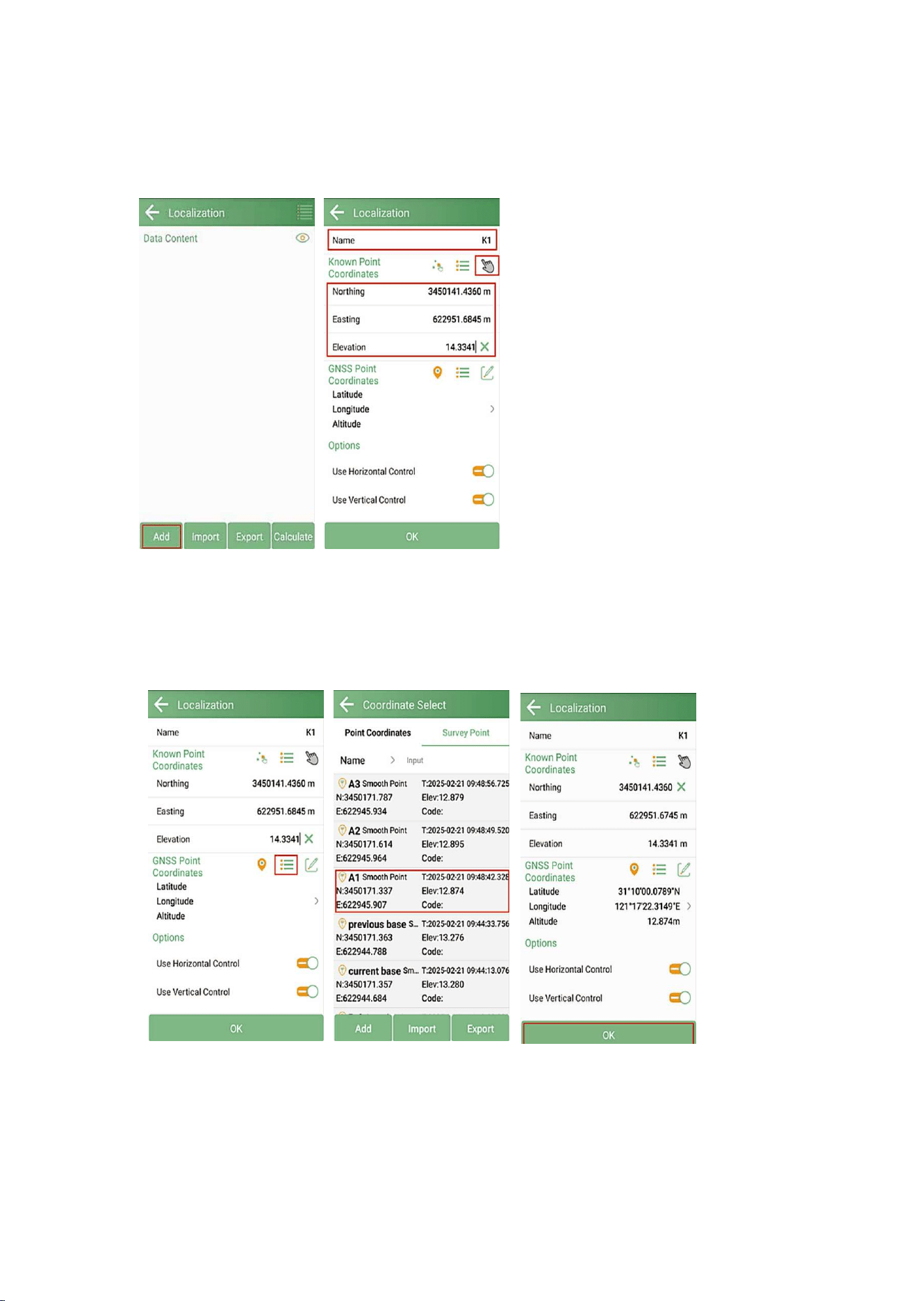
Click Add to add the corresponding pairs. Firstly, input the Known Point
Coordinates.
Then select the corresponding GNSS coordinates of the known point.
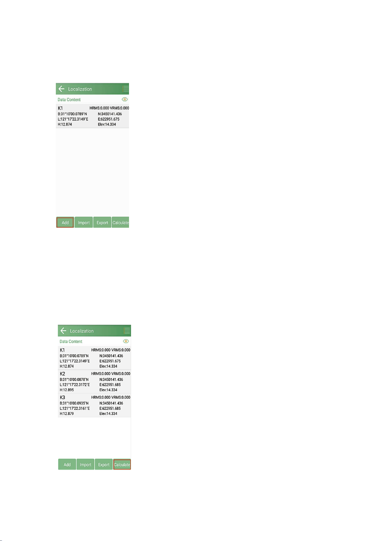
48
Add the remaining point pairs in sequence. You can also enter the known point in
point database in advance and select the input points.
After adding all the point pairs, click Calculate.
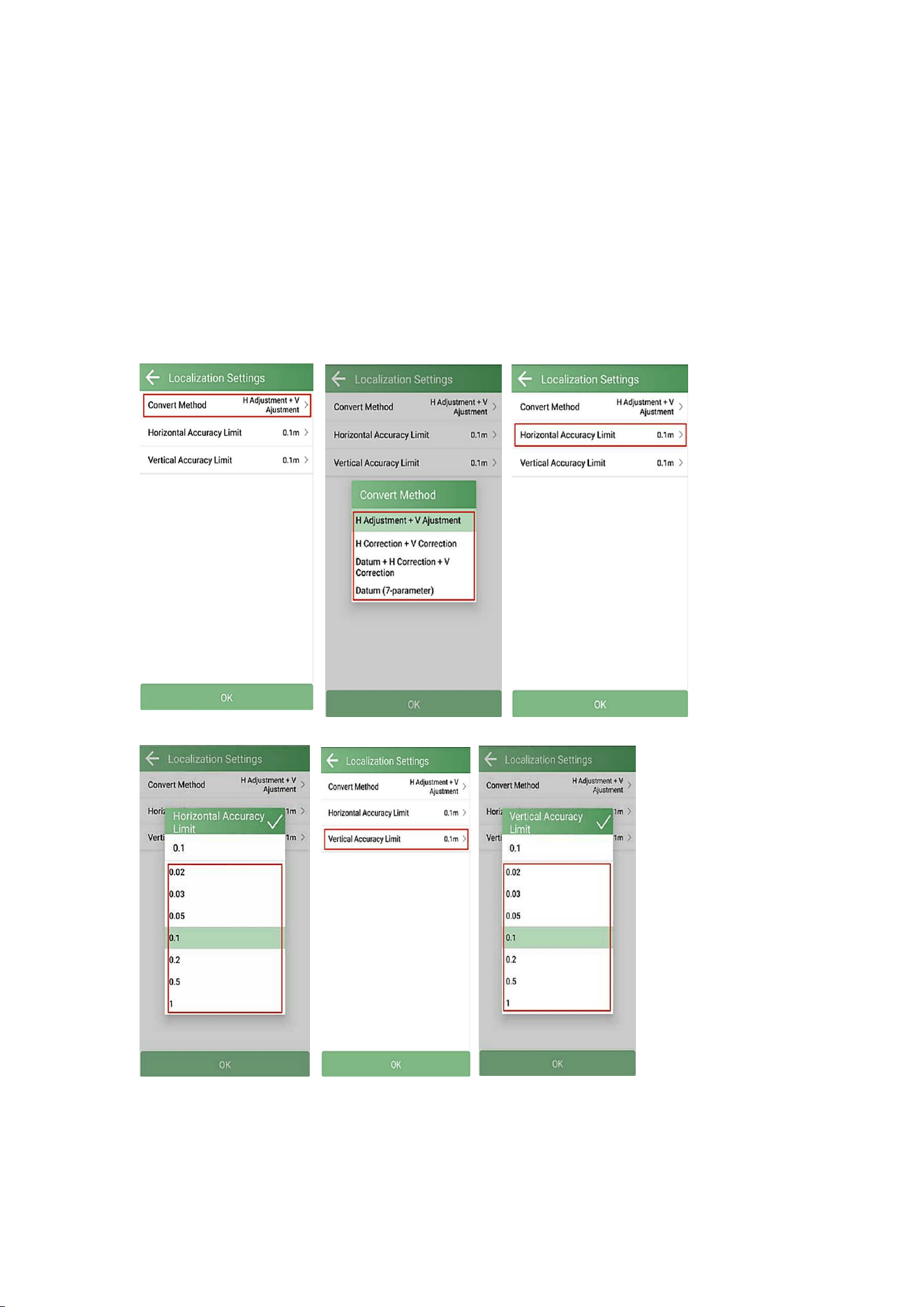
49
Select the convert method and the accuracy limit according to your project
requirements.
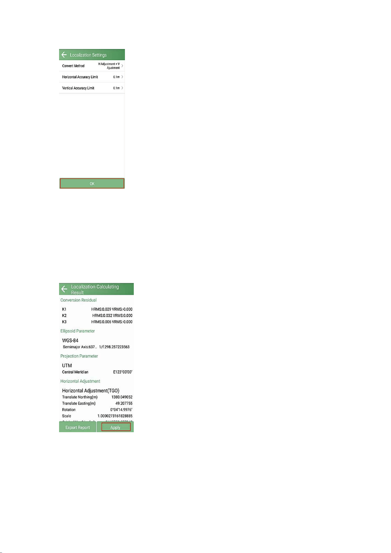
50
You can click Export Report to save the projected coordinate system parameters.
Click Apply to apply the localization.
51
3.5 Tilt Survey
If using the Xbase as a base station, there is no need to enable the IMU; however,
if using it as a rover, the IMU can be initialized to perform tilt measurements.
The XBase GNSS receiver features a built-in IMU module that supports tilt
surveying up to 60°. The system will accurately calculate the actual offset based
on the tilt angle, reducing the need to keep the range pole perfectly vertical
during measurements.
The tilt function option will appear in each survey/stakeout function
interface. You can click the icon to enable or disable tilt compensation.
Tilt initialization is required when using it for the first time or when the
calibration has expired.
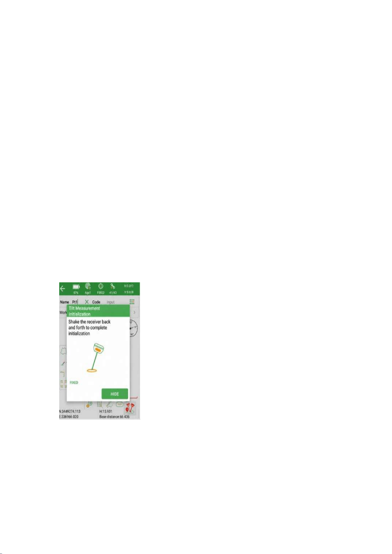
The following steps give an example of how to use tilt survey.
1.Open IMU: Go to survey >> Point Survey >> click the button to open.
After enabling the tilt IMU button, the system will prompt you to check the
antenna information, please check whether the antenna height is correct.
52
2. Initialization
After clicking the IMU button, you can follow the guidance on the interface to
complete it.
During the operation, ensure that the receiver can search for satellites and obtain
a fixed RTK solution.
NOTE: If the receiver is powered off or reset, IMU initialization must be
performed again.
In survey interface, you can find the bubble indicator and angle value showing
how you tilt the pole in real time. To ensure the accuracy, please keep the tilt
angle less than 60° . When the pole tilts within 60°, the built-in IMU precisely
calculates the actual offset, the accuracy of which can be accurate to ±2.5cm.
NOTE:If rapid rotation, falling and other violent movements cause IMU status
loss, it needs to be reinitialized by gently shaking the pole for about 5 seconds.
53
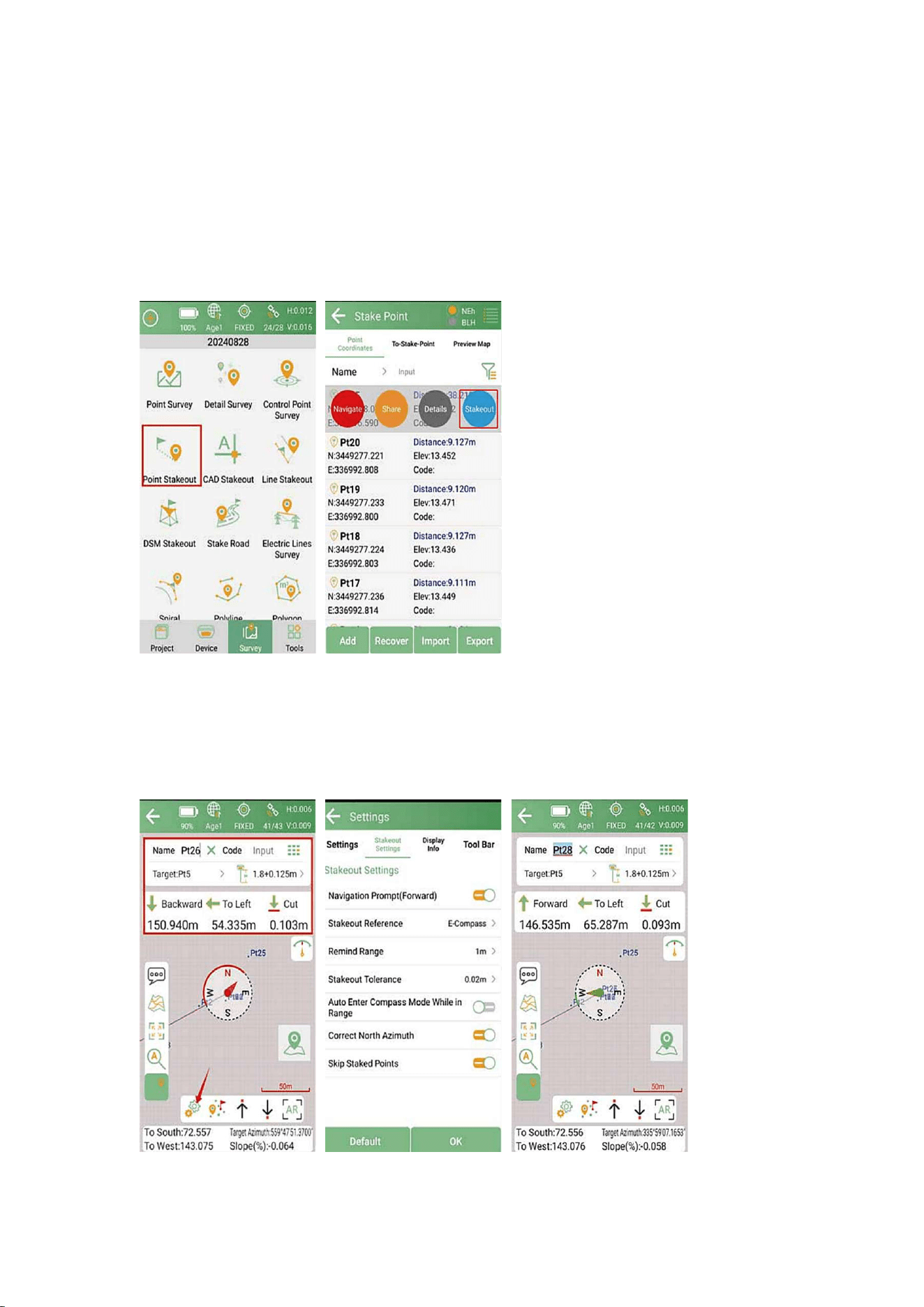
3.6 Point Stakeout
Go to Point Stakeout interface, you can select a point from the point database to
Stakeout. You can add or import the required point coordinates into the point
database.
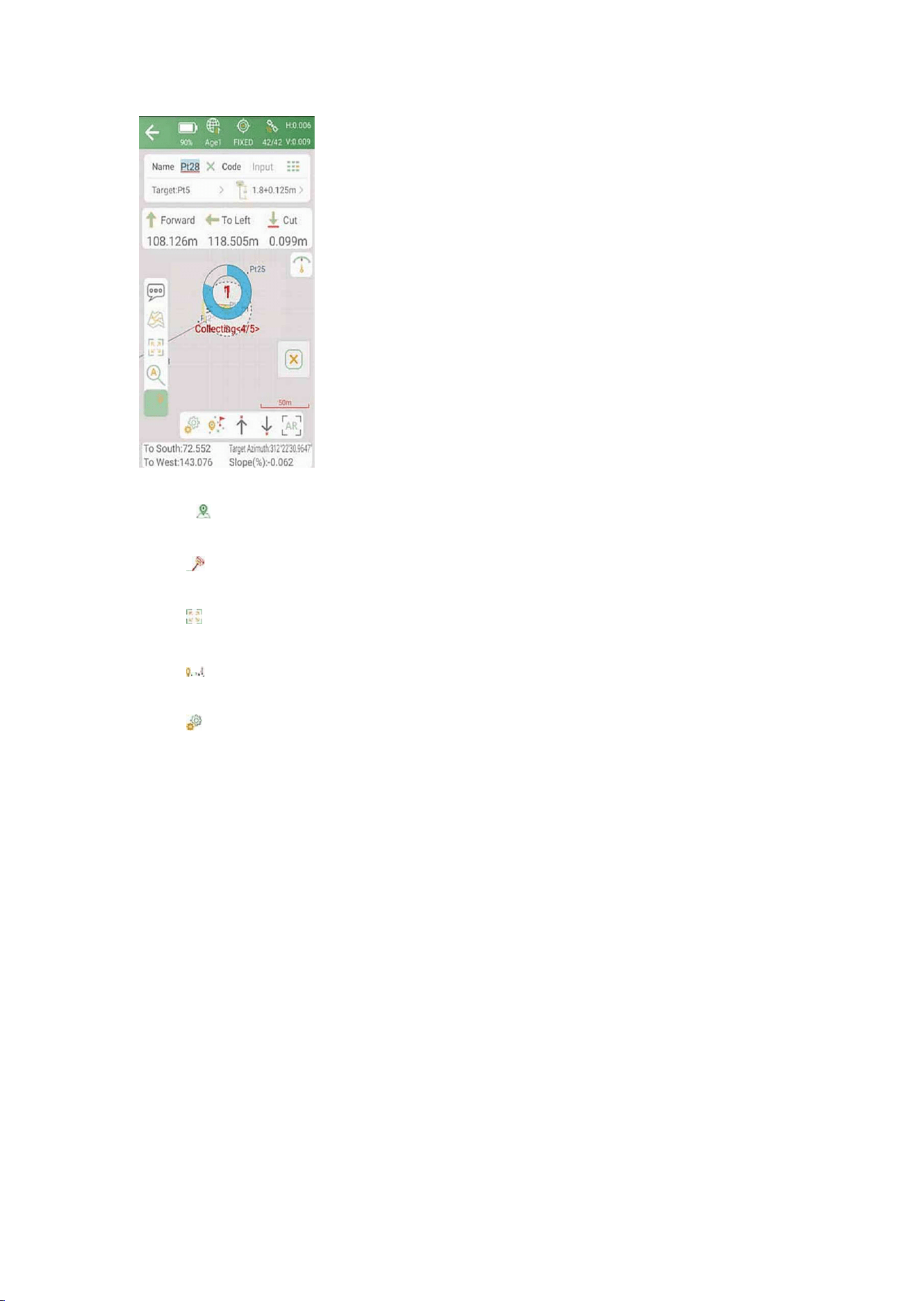
Select a point to stake, and follow the navigation guidance displayed on the map
for staking points/lines. Once you get close enough to the target point, it will
alarm you based on the alarm range you have set.
54
Click to start or stop staking points
Click to enable or disable IMU
Click to automatically zoom to the full image
Click to jump to the current point
Click to set up the slide-out settings, display information and toolbar, you
can edit the prompt range and range error
3.7 Export points data
Tap Export in Project interface to export point data. Also, click More formats to
export the survey points in various formats like stake points/ lines, DXF, SHP,
KML, RAW, RW5, HTML, CASS feature result.
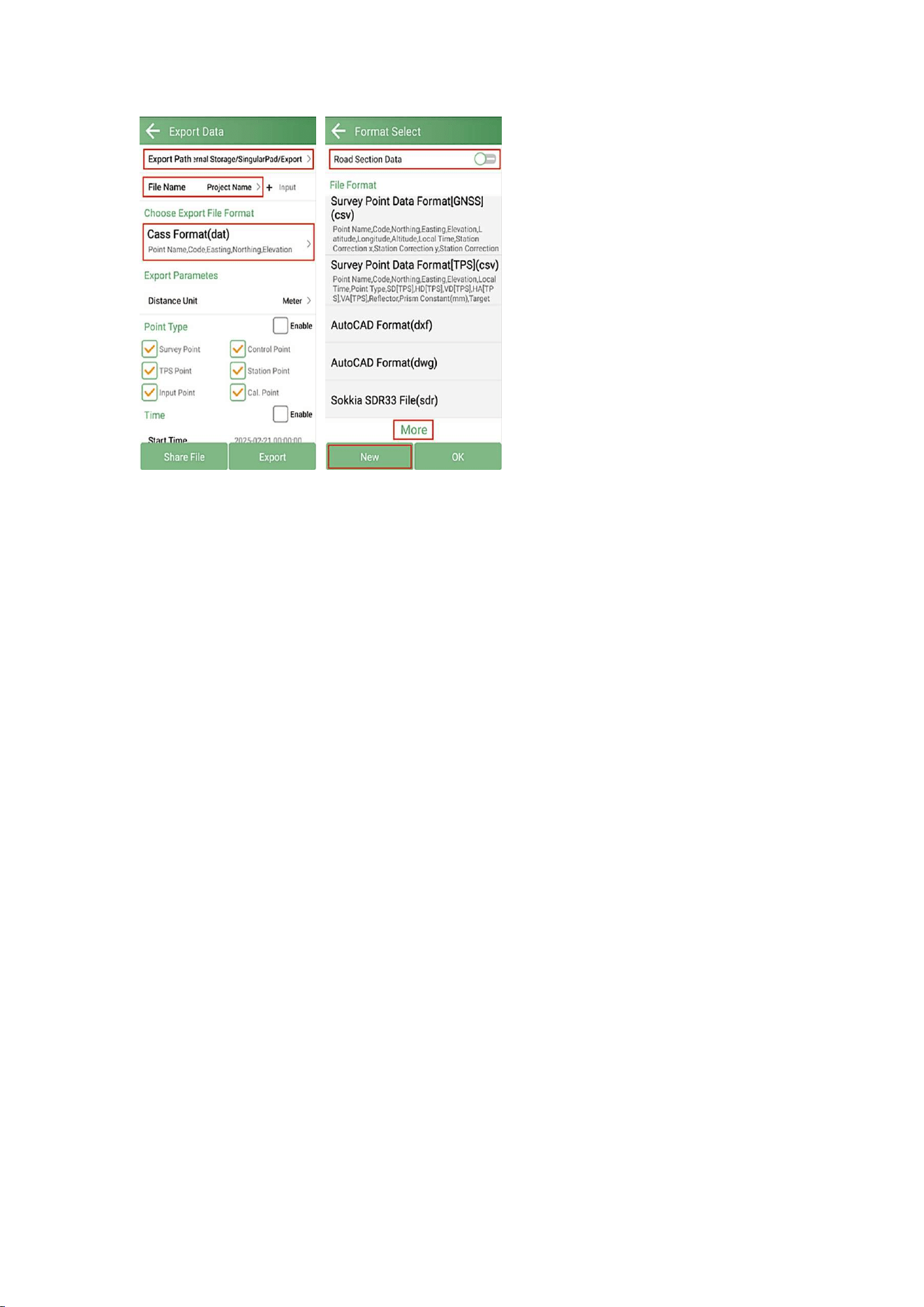
55
Export Path: the default export path is internal storage/SingularPad/export; you
can also change to any other path if required.
• File Name: support project name, operator, data, data time
• Export File Format: support *.csv, *.dat, *.txt, *.kml, etc.
• Distance Unit: support meter, US survey feet and international feet
• Road section data: open to export road section data
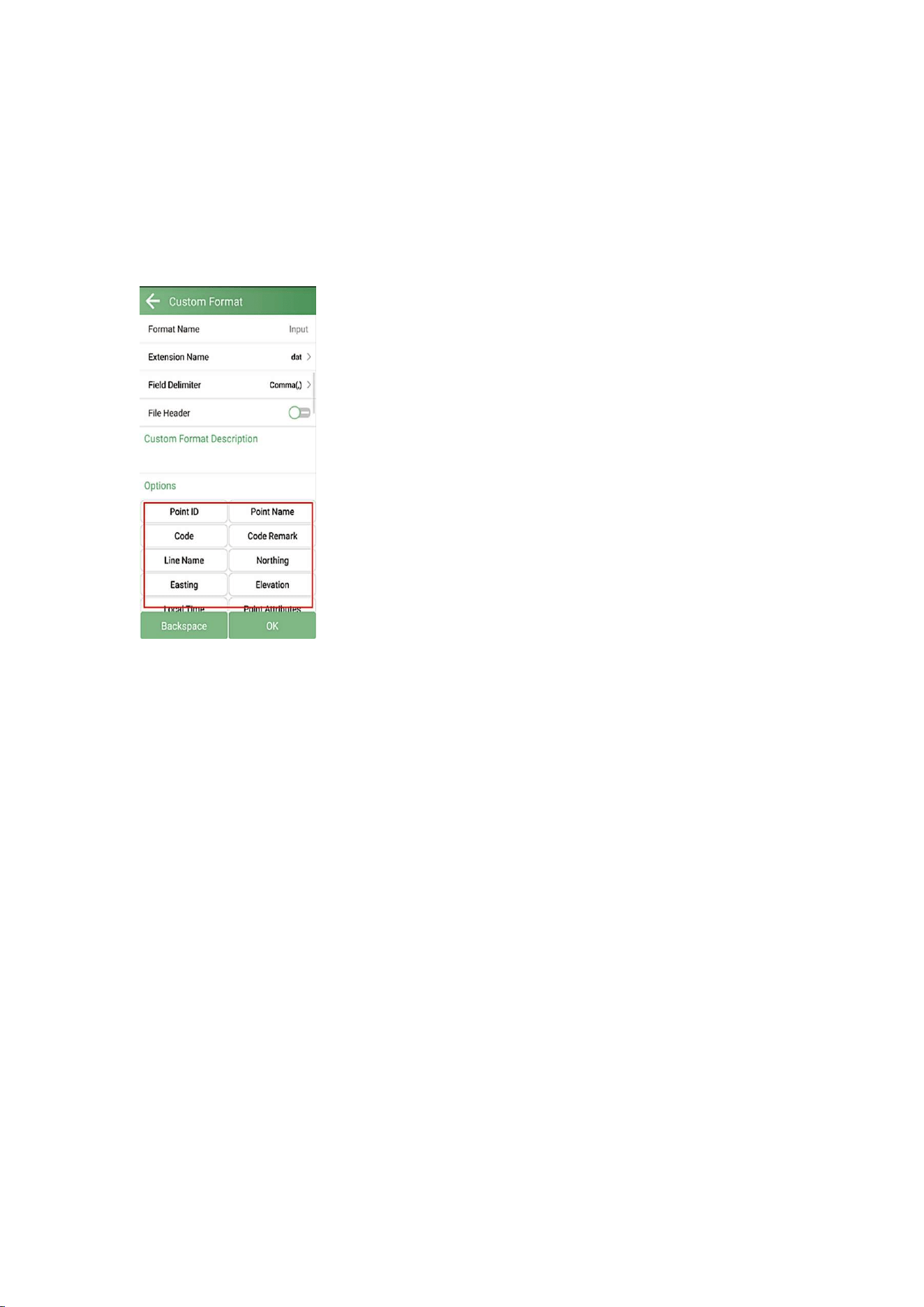
Additionally, you can click New to create a user defined type. The elements
include: id, name, code, latitude, longitude, altitude, northing, easting, elevation,
N, E, Z, type, local time, UTC time, solution status, Age, max delay, min delay, used
satellites, tracked satellites, cut-off angle, mount point, measurement method,
repeat, start date, end time, RMS, HRMS, VRMS, PDOP, VDOP, speed, heading,
antenna type, measuring type, measuring height, antenna height, base id, base
latitude, base longitude, base altitude, distance to ref, original latitude, original
longitude, original altitude, undulation height, station correction h, inclination
correction, pitch, roll, yaw, inclined angle, projected angle, stakeout type, target,
station, offset, north diff, east diff, elevation diff.
56
For the points, lines and polygons you surveyed in point survey, you can export
as .dxf file, then you can edit them in third party CAD software, import to base
map to check, or import to CAD to stake. Choose the data that you want to export
including survey point, input point, control point, stake point, line and polygon,
and the layer properties include name, code and height.

57
4 STATIC SURVEY
This chapter describes how to conduct static survey through Xbase receiver and
SingularXYZ Converter software. For static survey, Xbase supports SingularXYZ
binary format (*.XYZ), which is a raw observation data format. You can convert it
to RINEX format via SingularXYZ Converter Software.
For the converter software, please contact the SingularXYZ support team at
4.1 Static Data Collection
Static survey is mainly used for the control point survey. To reach millimeter
accuracy results, please follow the recommendations below:
•At least 3 GNSS receivers are required to form a stable triangulation network.
• It is better to collect static data on the known point.
• Power off the receiver before moving to other observation site.
• For the convenience of post-process static observation raw data, record the
station name, receiver SN, antenna height, start and end time for each
observation site.
For convenient operation, you can start recording static data by double-pressing
the function button on the front panel. The flashing yellow indicator on the
function button indicates that static data recording has begun at a 1Hz frequency.
If you need to do more detailed settings about static survey, please follow these
steps to configure them in the SingularPad software.
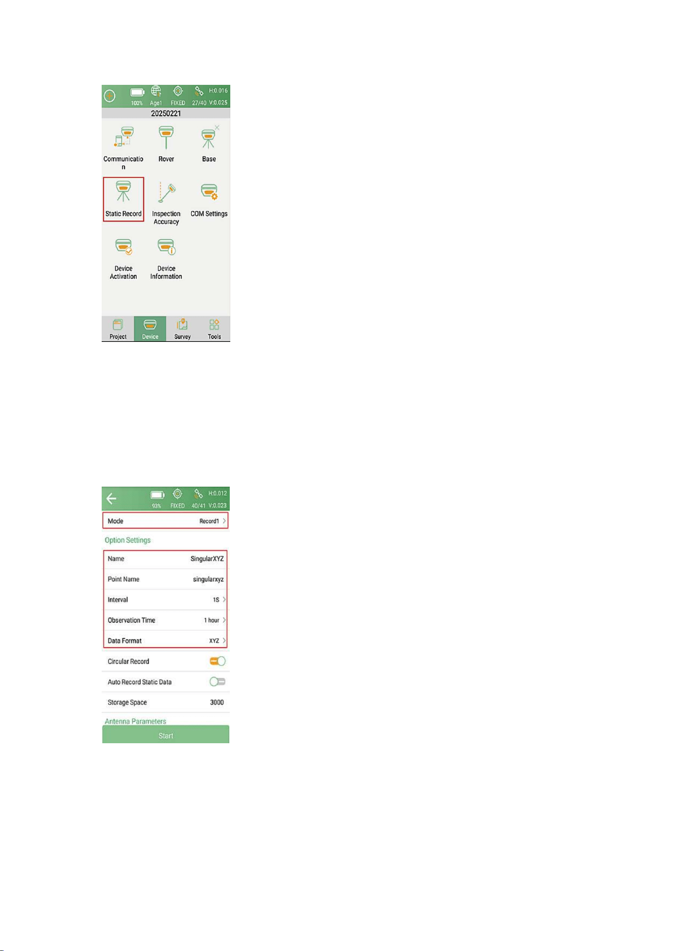
1. Go to Device >> Static Record for static settings.
58
2. Choose the Record mode. There are two record modes and they can record
static data at the same time.
Options Settings interface: Input Record name and Point name. Set the Collection
Interval, Observation Time and Data Format.
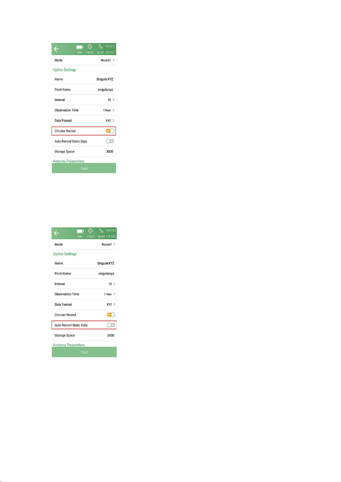
3. Turn on/off the Circular Record according to your needs. If this option is
turned on, the receiver will automatically delete the earliest recorded data to
keep recording when the storage space is full.
59
4.Enable/disable the Auto Record Static Data according to your needs. If this
option is turned on, the receiver will automatically record static data after it is
power on.
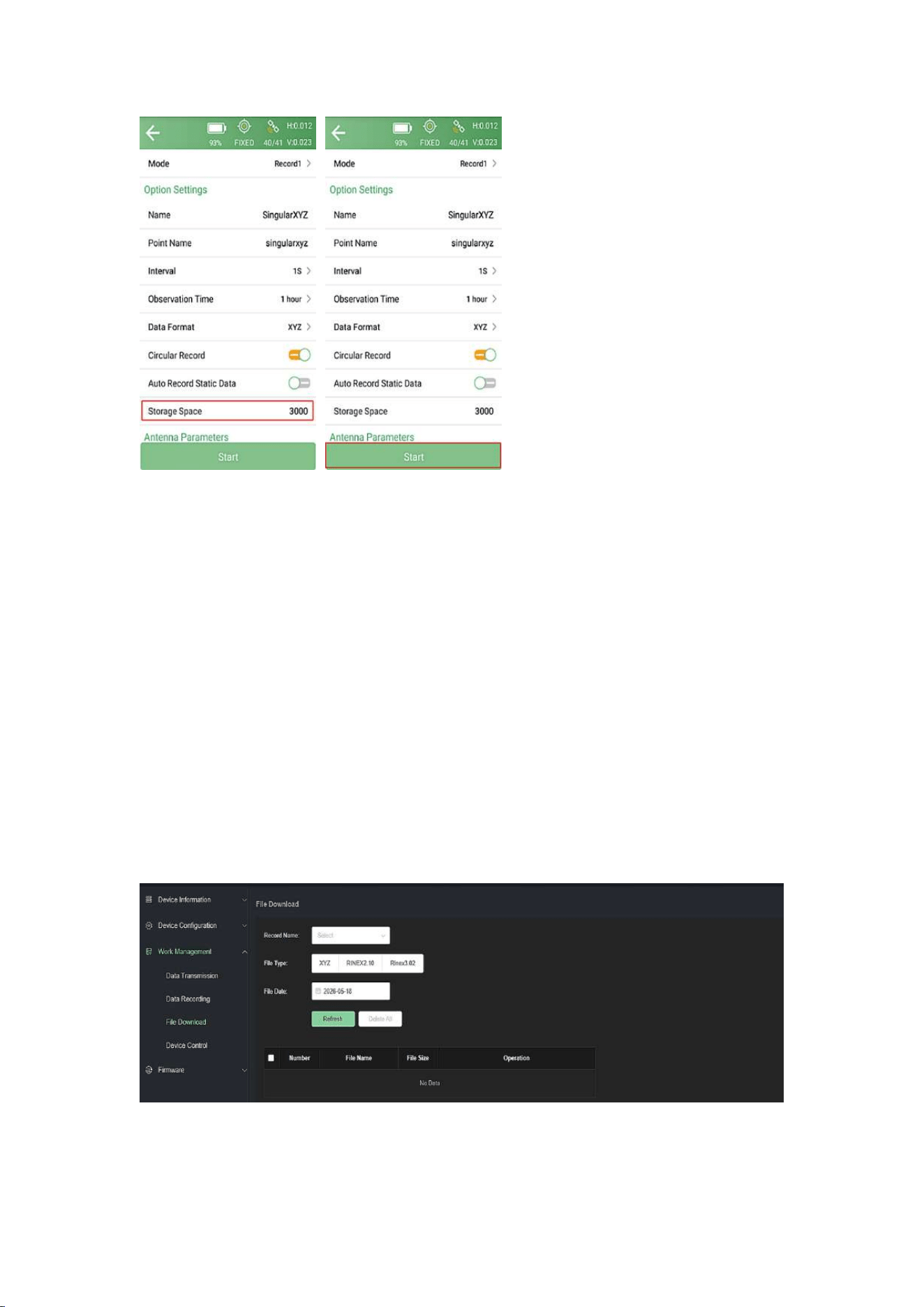
5.Set the Storage Space at the end (unit: MB). It will limit the amount of data
that receiver can record.
6.Click start to start static data collection.
60
4.2 Static Data Download
The raw observation data is saved in the internal memory of the Xbase receiver.
The specific steps to download the static data from the Xbase receiver are as
follows:
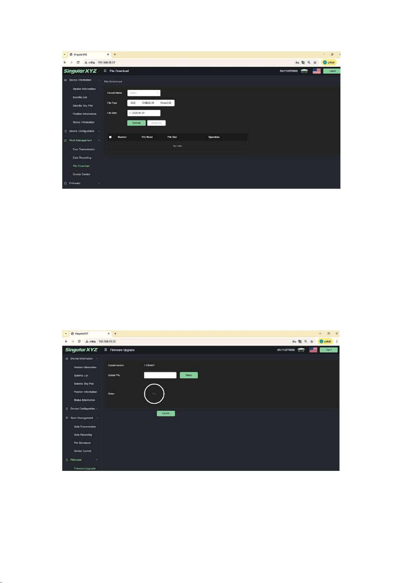
Refer to Chapter 5.1 Access the web interface to go to the Xbase web page.
Go to Work management >> File Download, select the corresponding record
name, file type and date to filter and download the static data.
61
4.3 RINEX Conversion
After download raw observation data to PC, you can convert the data format from
SingularXYZ binary format (*.XYZ) to Rinex in SingularXYZ Converter software.
The following steps give an example of Rinex conversion.
1. Start SingularXYZ Converter software.
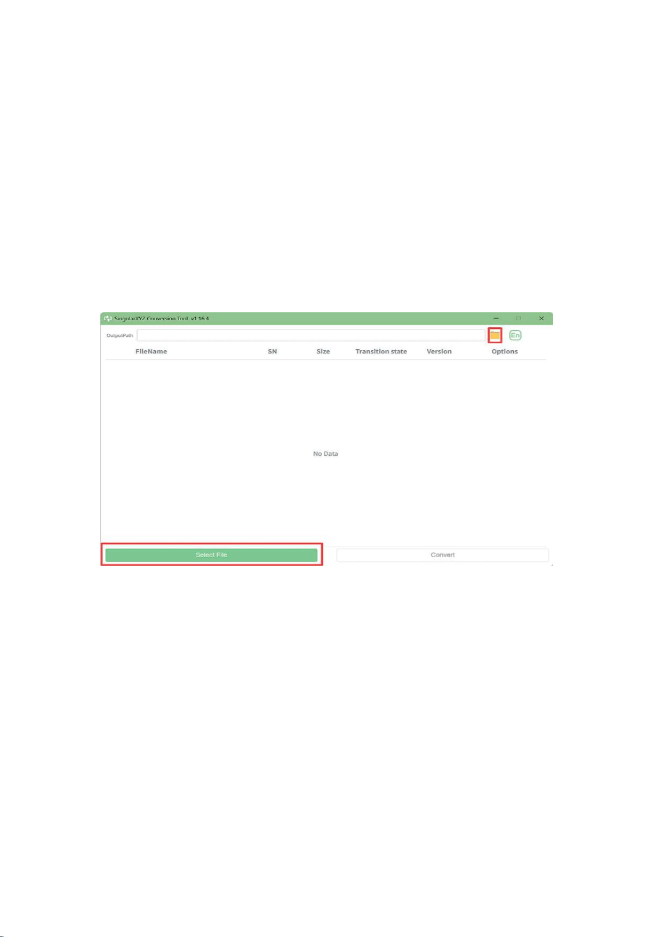
2. Click the file folder icon to set the output path and click Select file to import
the binary file.
62
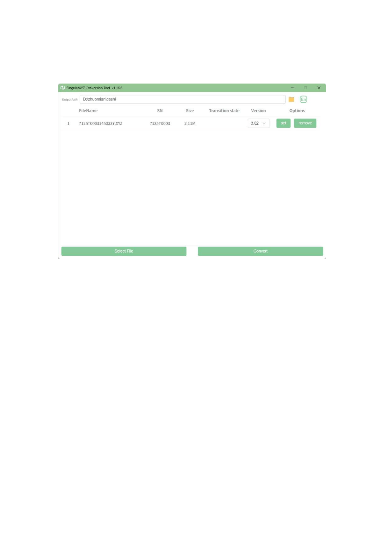
3. Click convert to start converting XYZ to Rinex, and the Rinex files will be
output to the output file path.
NOTE: The output path and GNSS raw data storage path must contain only English letters and
numbers.
63
5 WEB UI INTRODUCTION
This chapter mainly introduces the function of Web UI.
5.1 Access the web interface
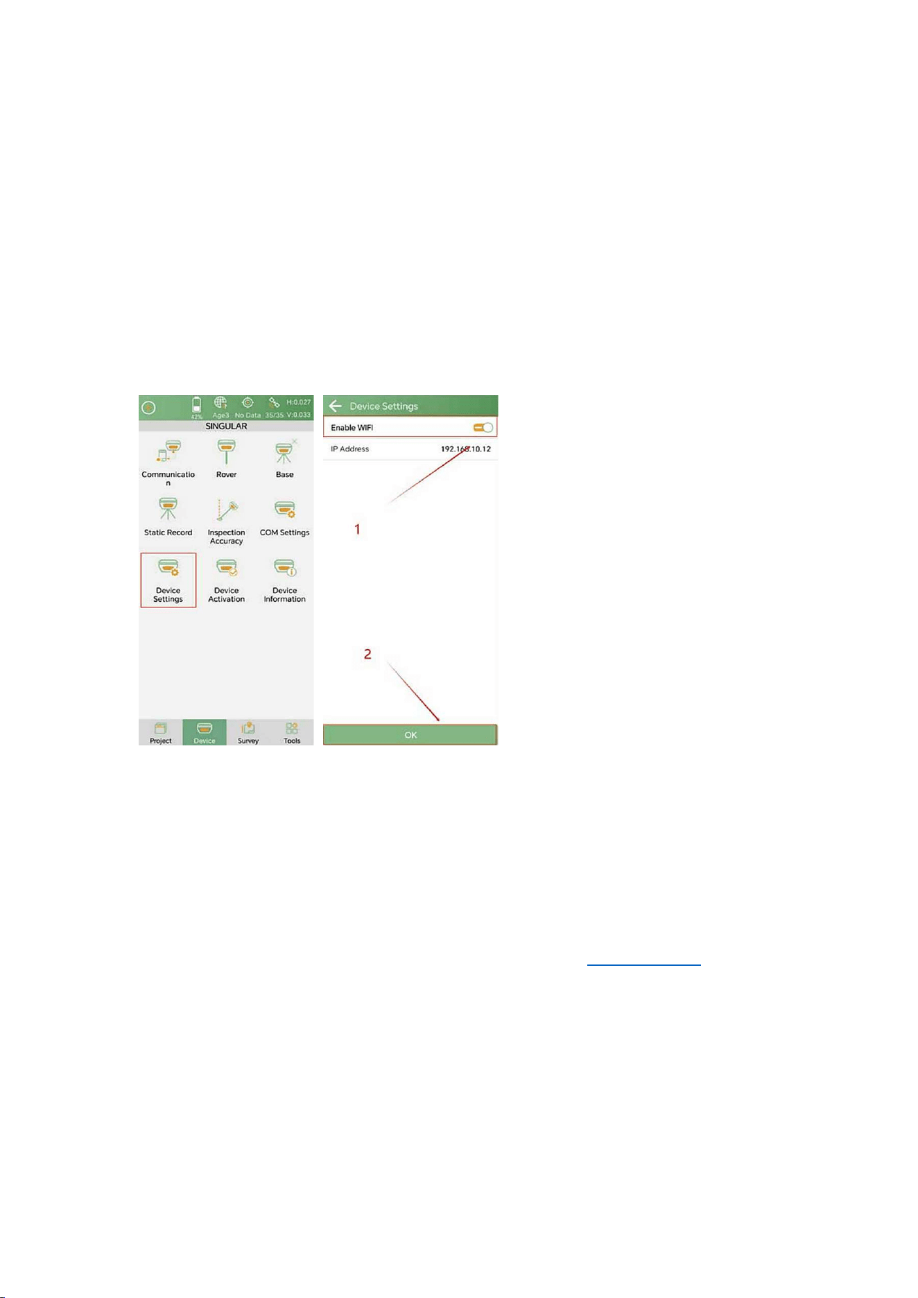
After you connect Xbase GNSS Receiver to SingularPad via Bluetooth, go to
Device >> Device Settings. Keep the default IP address and enable WIFI, click OK.
NOTE: By default, the Xbase receiver starts with Bluetooth enabled and Wi-Fi
disabled. Bluetooth and Wi-Fi cannot be enabled simultaneously. Therefore, to
use Wi-Fi, you need to enable it through the PAD software. After restarting the
device or configuring it via the web interface, Bluetooth will be enabled again.
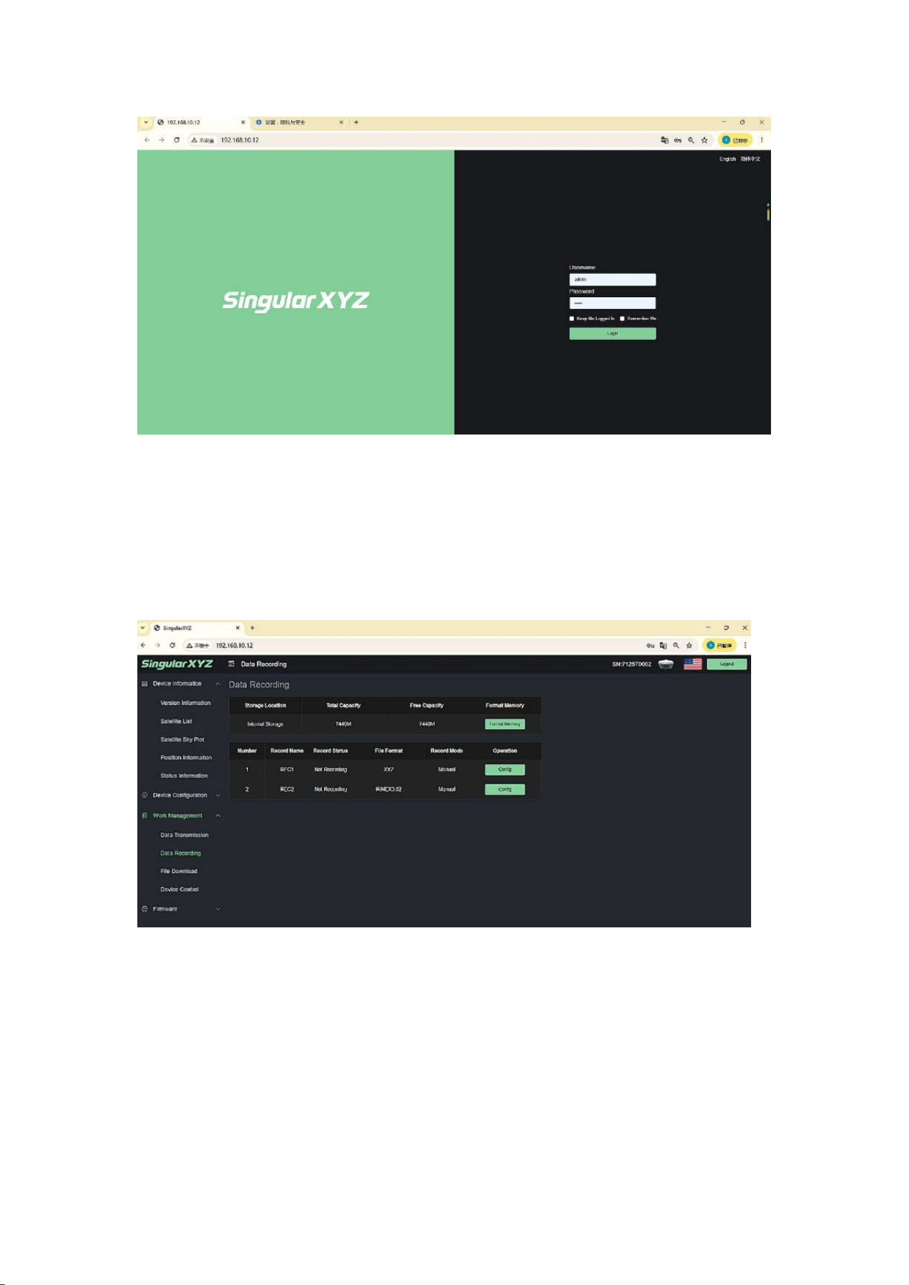
Connect PC or mobile devices to Xbase WiFi (Name: SN of Xbase, Password:
12345678). Open browser and enter the web page via IP 192.168.10.12
(Username: admin, Password: admin).
64
5.2 Work Management
In Data Recording, you can set the parameters of the collected static data and
start record. You can also format memory in this interface.
In file download section, you can download recorded static data.
65
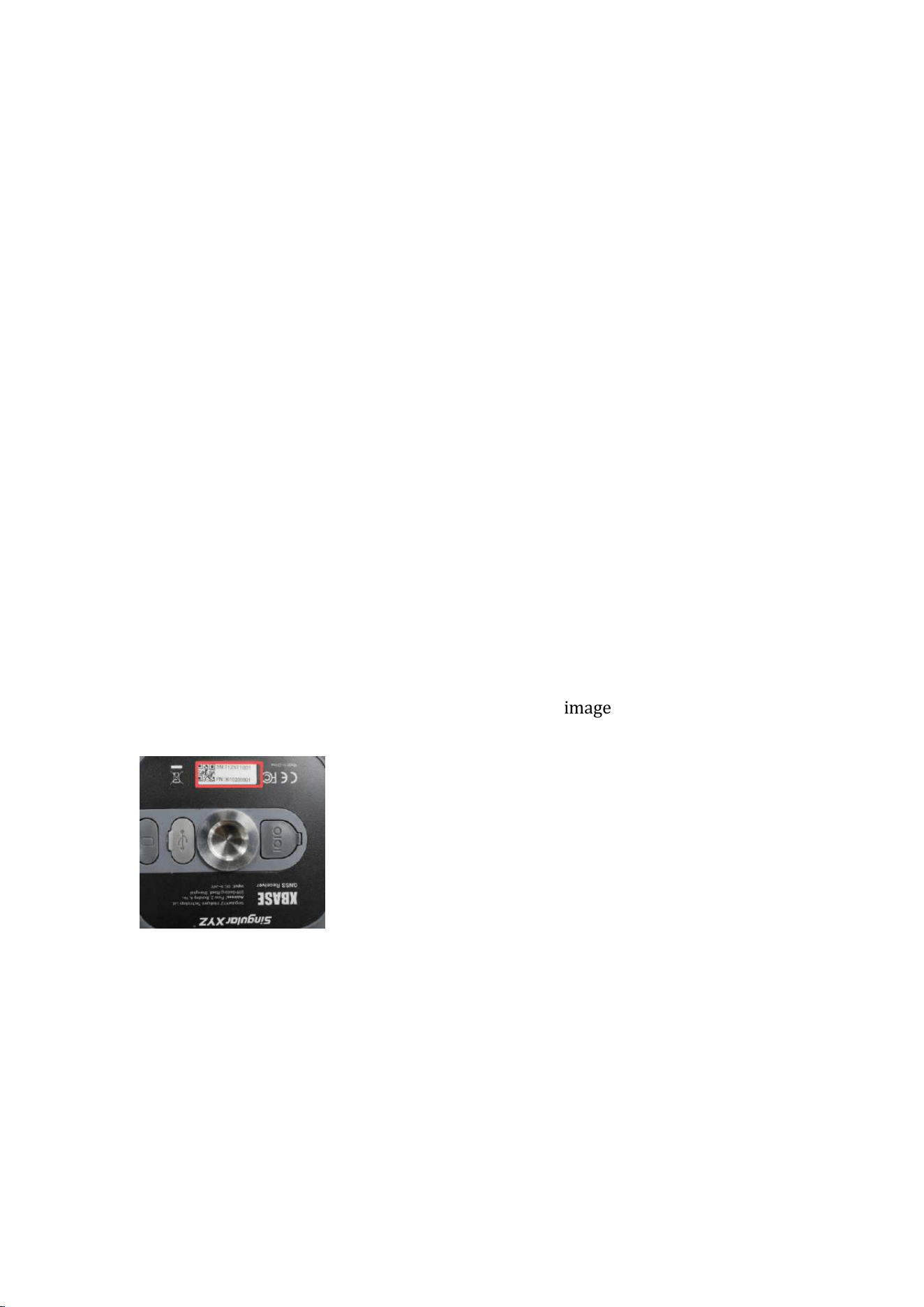
5.3 Firmware Upgrade
This function interface is used to upgrade the firmware version of the device.
1. Select the firmware (*.bin file) in this interface and click Update to upload the
firmware package.
2. After the upload complete, the device will automatically restart and the
upgrade is finished.
66
6 TROUBLESHOOTING
If you encounter any issues that are not addressed in this manual, please contact
SingularXYZ support team for assistance. To help our support engineers diagnose
and resolve the issue efficiently, Please send the following information to our
support team for further assistance.
• Serial number of your Xbase device
• Problem description with supplementary video/screenshots
• Debug logs and project file
6.1 How to Find Serial Number
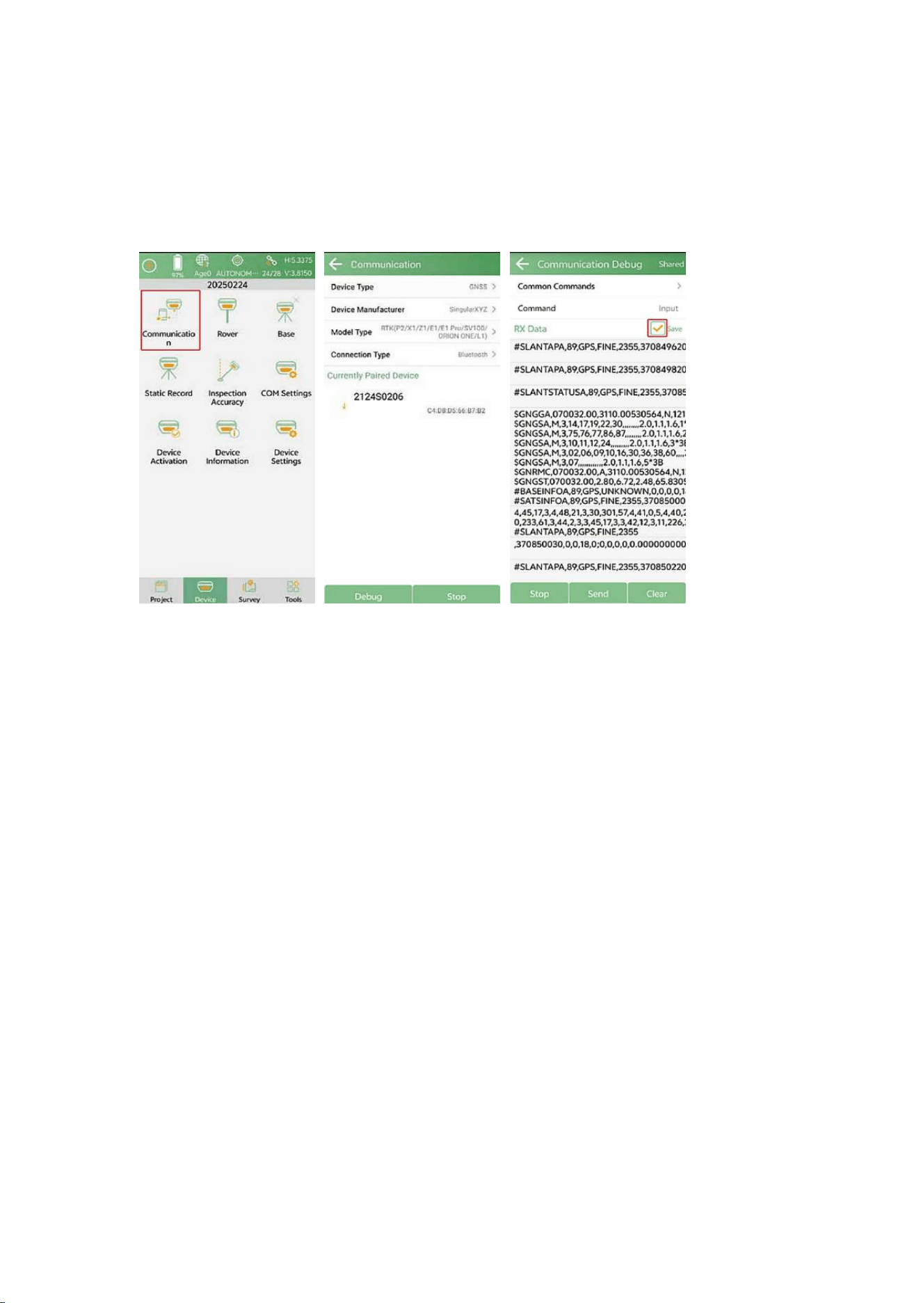
The serial number is a unique combination of numbers and letters assigned to
your Xbase receiver for identification and technical support purposes.
Find serial number
Find the serial number of your Xbase as shown in the image below.
6.2 How to Get Debug Data & Project File
6.2.1 Save Debug File
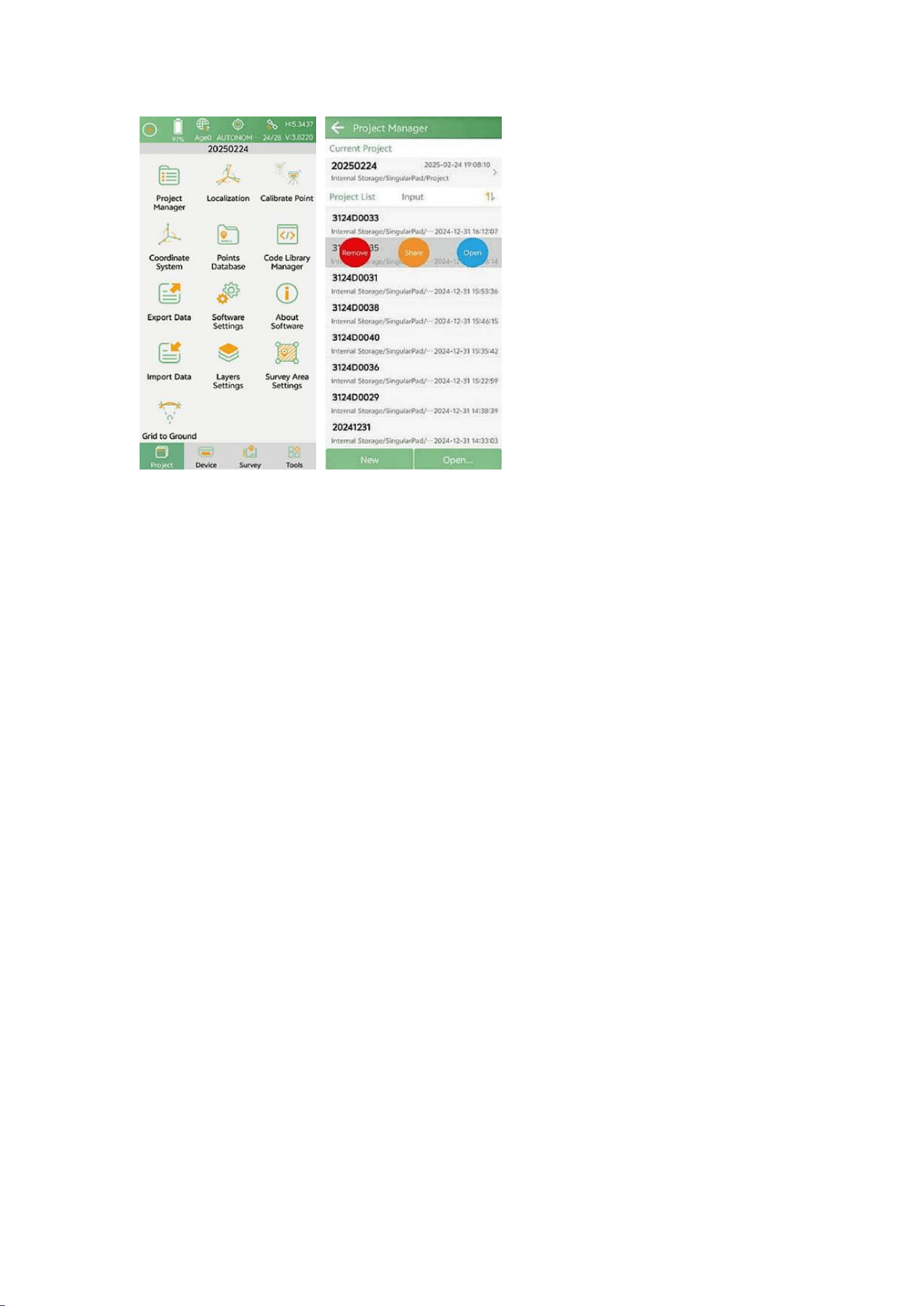
The Debug data provides information about your current Xbase internal state,
helping support team facilitate troubleshooting.
67
After connecting the device, you can access the Debug section.
Enter Device>>Communication>>Debug, then enable Save option to save debug
file, which will be stored in the System folder (/SingularPad/Debug).
6.2.2 Share Project File
The project file and its parameters will also help us identify the issues. You can
share your project with us by following these steps:
Enter Project>>Project Manager, select your project and click Share.
68
69
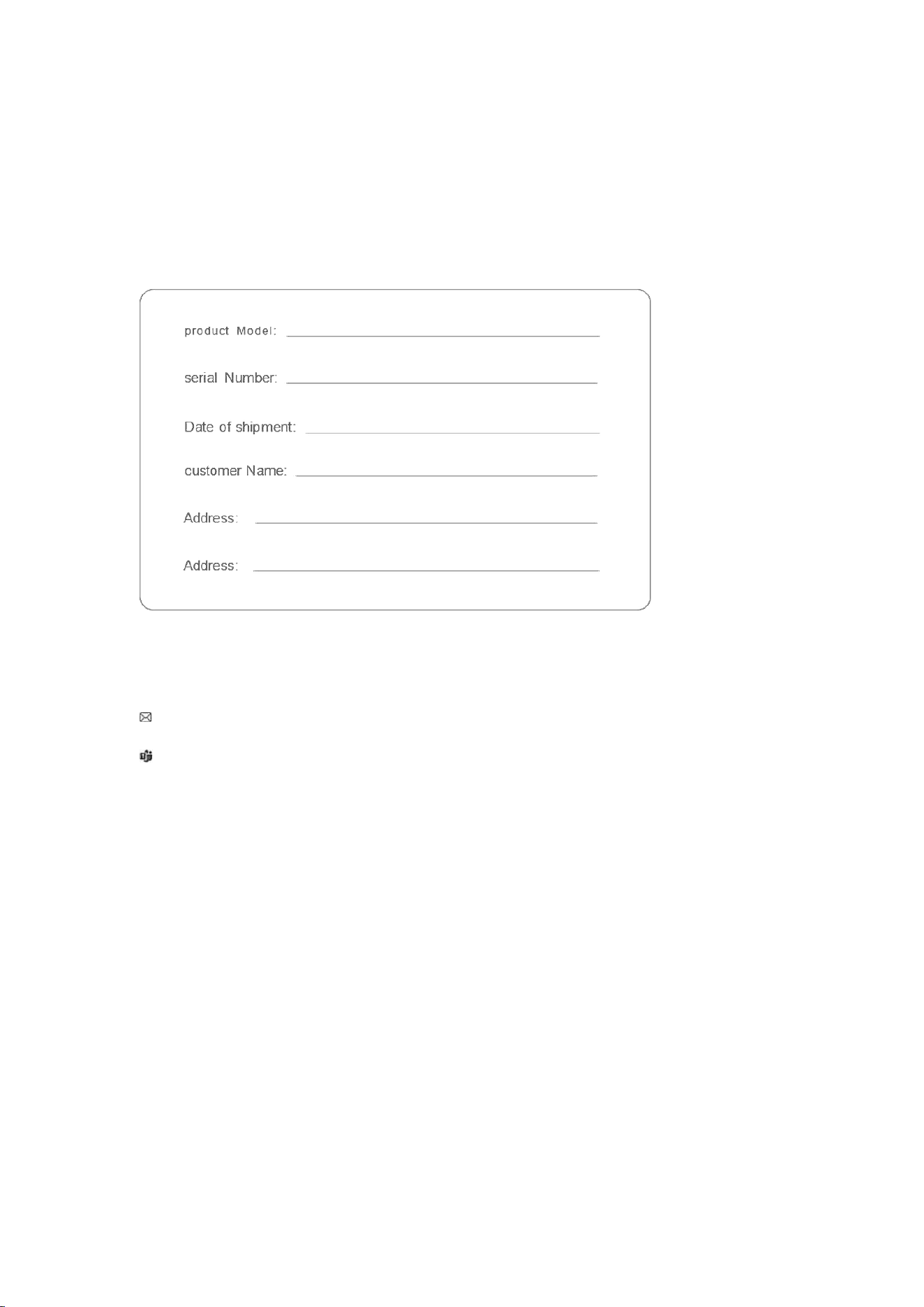
WARRANTY CARD
If you meet any issues while using the product, please contact SingularXYZ
support team or your local SingularXYZ distributor partner for supporting and
debugging first
To request warranty service, please contact your local SingularXYZ distributor or
our support team at:
Support.SingularXYZ
Warning and Caution
An absence of specific alerts does not mean that there are no safety risks
involved. A
Warning or Caution information is intended to minimize the risk of personal
injury and/or damage to the equipment.
WARNING - A Warning alerts you to a potential risk of serious injury to your
person
and/or damage to the equipment, because of improper operations or wrong
settings of the equipment.
CAUTION - A Caution alerts you to a possible risk of damage to the equipment

70
and/or data loss.
Warranty Notice
SingularXYZ does not warranty devices damage because of force majeure
(lighting, high voltage or collision).
SingularXYZ does not warranty the disassembled devices.
FCC Warning
This device complies with part 15 of the FCC rules. Operation is subject to the following two conditions: (1) this device may not
cause harmful interference, and (2) this device must accept any inte rference received, including interference that may cause
undesired operation.
Changes or modifications not expressly approved by the party responsible for compliance could void the user's authority to
operate the equipment.
NOTE: This equipment has been tested and found to comply with the limits for a Class B digital device, pursuant to part 15 of the
FCC Rules. These limits are designed to provide reasonable protection against harmful interference in a residential installation.
This equipment generates uses and can radiate radio frequency energy and, if not installed and used in accordance with the
instructions, may cause harmful interference to radio communications. However, there is no guarantee that interference will not
occur in a particular installation. If this equipment does cause harmful interferenceto radio or television reception, which can be
determined by turning the equipment off and on, the user is encouraged to try to correct the interference by one or more of the
following measures:
• Reorient or relocate the receiving antenna.
• Increase the separation between the equipment and receiver.
• Connect the equipment into an outlet on a circuit different from that to which the receiver is connected.
• Consult the dealer or an experienced radio/TV technician for help.
Radiation Exposure Statement
This equipment complies with FCC radiation exposure limits set forth for an uncontrolled environment. This equipment should
be installed and operated with minimum distance 60cm between the radiator and your body.