Far Range, Affordable
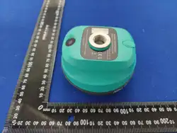
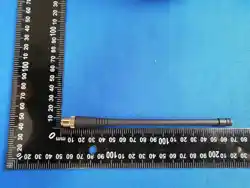
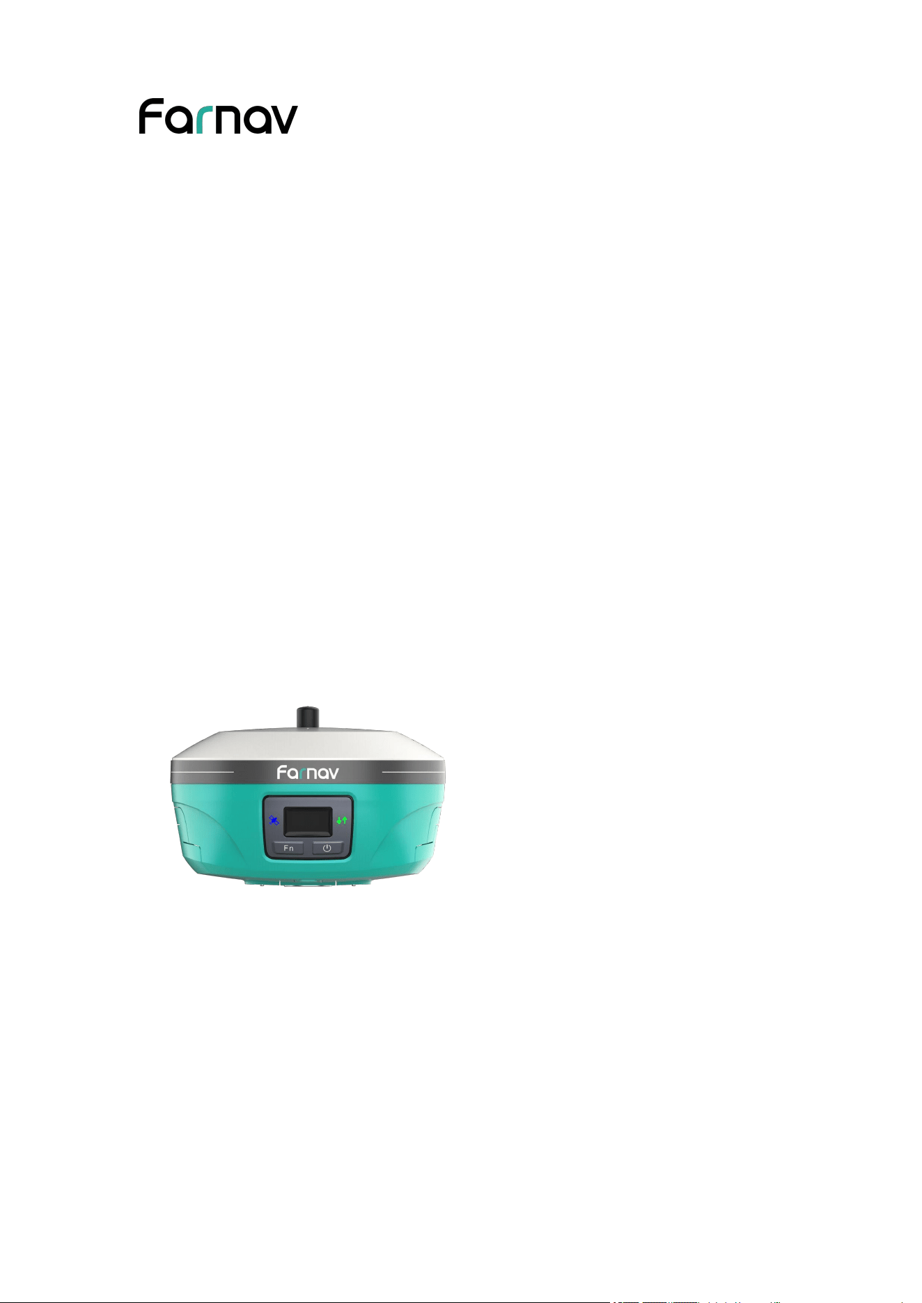
Farnav Nbase GNSS
USER GUIDE
Survey & Construction | Feb 2026

Table of Content
Preface
...................................................................................................................1
Copyright
............................................................................................................... 1
Copyright
....................................................................................................... 1
Trademarks
.................................................................................................... 1
Safety Warnings
..................................................................................................... 1
FCC Statement
.......................................................................................................1
CE Interference Statement
.....................................................................................2
Brazil
......................................................................................................................3
Conformity to Japanese regulations
.......................................................................3
1 Introduction
........................................................................................................4
1.1 Safety Information
........................................................................................... 4
1.2 Regulations and Safety
.................................................................................... 4
1.3 Technical Support
............................................................................................ 5
1.4 Disclaimer
........................................................................................................5
1.5 Your Comments
............................................................................................... 5
2 Getting Started with Nbase
................................................................................ 6
2.1 About the Receiver
...........................................................................................6
2.2 Parts of the Receiver
........................................................................................ 6
2.2.1 Front Panel
............................................................................................6
2.2.2 Lower housing and ports
.......................................................................8
2.3 Batteries and Power
......................................................................................... 9
2.3.1 Internal Batteries
...................................................................................9
2.3.2 Charging the Battery
.............................................................................9
2.3.3 Battery Safe
...........................................................................................9
2.4 Inserting Battery and SIM Card
.....................................................................10
2.4.1 Inserting battery
.................................................................................. 10
2.4.2 Inserting SIM card
.............................................................................. 11
2.5 Product Basic Supply Accessories
.................................................................12
2.6 Connecting to a Controller
.............................................................................13
2.6.1 Connecting via Wi-Fi with eField Software
....................................... 13
2.6.2 Connecting via Bluetooth with eField Software
.................................13
2.7 Downloading Logged Data
............................................................................14
2.7.1 FTP Download
....................................................................................14
3 Front Panel Operation
......................................................................................17
3.1 Main Operation Menus
.................................................................................. 17
3.2 Configure the Working Mode
........................................................................ 19
4 Equipment Setup and Operation
......................................................................23
4.1 Post-processing Base Station Setup
...............................................................23
4.2 Real-Time Base Station
................................................................................. 24
4.2.1 Real-Time Base Station Setup
............................................................ 25
4.2.2 Ultra Base
........................................................................................... 25

4.3 Real-Time Rover Station
............................................................................... 27
4.3.1 Real-Time Rover Station Setup
.......................................................... 27
4.3.2 Ultra Rover
......................................................................................... 28
5 Configuring Through a Web Browser
.............................................................. 29
5.1 Status Menu
................................................................................................... 30
5.1.1 Position Submenu
............................................................................... 31
5.1.2 Activity Submenu
............................................................................... 31
5.1.3 Google Map Submenu
........................................................................ 32
5.2 Satellites Menu
.............................................................................................. 32
5.2.1 Tracking Table Submenu
.................................................................... 33
5.2.2 Tracking Info. Table Submenu
............................................................33
5.2.3 Tracking Skyplot Submenu
.................................................................34
5.2.4 Satellite Activation Submenu
..............................................................34
5.2.5 Tracking Enable Submenu
.................................................................. 35
5.3 Receiver Configuration Menu
....................................................................... 35
5.3.1 Description
..........................................................................................36
5.3.2 Antenna Configuration Submenu
........................................................36
5.3.3 Reference Station Settings Submenu
..................................................37
5.3.4 Receiver Reset Submenu
.................................................................... 38
5.3.5 Languages Submenu
........................................................................... 39
5.3.6 User Management Submenu
...............................................................39
5.3.7 HCPPP Settings
.................................................................................. 39
5.4 Data Recording Menu
....................................................................................39
5.4.1 Log Settings Submenu
........................................................................40
5.4.2 FTP Push Settings Submenu
...............................................................42
5.4.3 FTP Push Log Submenu
..................................................................... 42
5.5 IO Settings Menu
...........................................................................................43
5.5.1 IO Settings Submenu
.......................................................................... 43
5.6 Network Setting Menu
...................................................................................49
5.6.1 Description Submenu
..........................................................................50
5.6.2 Mobile Network Setting Submenu
..................................................... 50
5.6.3 Email Alarm Submenu
........................................................................51
5.6.4 HTTP Submenu
.................................................................................. 51
5.6.5 HTTPS Submenu
................................................................................ 52
5.6.6 FTP Service Submenu
.........................................................................52
5.7 Module Setting Menu
.................................................................................... 52
5.7.1 Description Submenu
..........................................................................53
5.7.2 WiFi Submenu
.................................................................................... 53
5.7.3 Bluetooth Settings Submenu
...............................................................53
5.7.4 Radio Settings Submenu
.....................................................................54
5.7.5 IMU Settings Submenu
.......................................................................54
5.8 Firmware Menu
..............................................................................................54

5.8.1 Firmware Info Submenu
..................................................................... 55
5.8.2 Hardware Version Submenu
............................................................... 55
5.8.3 Config File Submenu
..........................................................................55
5.8.4 System Log Download Submenu
....................................................... 56
5.8.5 User Log Submenu
............................................................................. 56
5.8.6 Firmware Update Submenu
................................................................ 56
5.8.7 GNSS Board Upgrade Submenu
.........................................................57
5.8.8 GNSS Registration Submenu
..............................................................58

Farnav Nbase GNSS USER GUIDE
| 2026-02 P a g e | 1
Preface
Copyright
Copyright
© Farnav | EFlX Geomatics Co., Ltd. All rights reserved. The Farnav is trademark of
EFlX Geomatics Co., Ltd. All other trademarks are the property of their respective
owners. Revision February 2026.
Trademarks
All product and brand names mentioned in this publication are trademarks of their
respective holders.
Safety Warnings
The Global Navigation Satellite System (GNSS) comprises several distinct satellite
constellations, each of which is under the jurisdiction of a specific government entity.
These entities bear the sole responsibility for ensuring the accuracy of their respective
systems and for maintaining the integrity of their satellite networks.
Do not rely solely on the device for critical navigation decisions. The GNSS signals
may be affected by atmospheric conditions, satellite availability, signal blockage, etc.
Be aware of the limitations of GNSS accuracy. It provides positioning information
with a certain level of accuracy, but errors (including manual error) and deviations can
occur.
Avoid prolonged exposure to strong magnetic fields, as they may interfere with the
operation of the device and affect its accuracy.
Do not dismantle or modify the device. Any unauthorized modification may result in
malfunction or damage and void the warranty.
Follow all instructions provided in the user manual for proper handling, charging, and
maintenance.
FCC Statement
This equipment has been tested and found to comply with the limits for a Class B
digital device, pursuant to Part 15 of the FCC Rules. These limits are designed to

Farnav Nbase GNSS USER GUIDE
| 2026-02 P a g e | 2
provide reasonable protection against harmful interference in a residential installation.
This equipment generates uses and can radiate radio frequency energy and, if not
installed and used in accordance with the instructions, may cause harmful interference
to radio communications. However, there is no guarantee that interference will not
occur in a particular installation. If this equipment does cause harmful interference to
radio or television reception, which can be determined by turning the equipment off
and on, the user is encouraged to try to correct the interference by one or more of the
following measures:
-- Reorient or relocate the receiving antenna.
-- Increase the separation between the equipment and receiver.
-- Connect the equipment into an outlet on a circuit different from that to which the
receiver is connected.
-- Consult the dealer or an experienced radio/TV technician for help.
This device complies with part 15 of the FCC Rules. Operation is subject to the
following two conditions:
This device may not cause harmful interference, and (2) this device must accept any
interference received, including interference that may cause undesired operation.
Changes or modifications not expressly approved by the party responsible for
compliance could void the user's authority to operate the equipment.
To maintain compliance with FCC's RF Exposure guidelines, This equipment should
be installed and operated with minimum distance 60cm between the radiator and your
body: Use only the supplied antenna.
CE Interference Statement
Declaration of Conformity: Hereby, EFIX Geomatics Co., LTD. declares that this F6
is in compliance with the essential requirements and other relevant provisions of
Directive 2014/53/EU. A copy of the Declaration of conformity can be found at EFIX
Geomatics Co., LTD.

Farnav Nbase GNSS USER GUIDE
| 2026-02 P a g e | 3
Brazil
Este equipamento nÃao tem direito à protecao contra interferência prejudicial e nao
pode causar interferência em sistemas devidamente autorizados. Para maiores
informacöes, consulte o site da ANATEL-www.anatel.gov.br.
Conformity to Japanese regulations
Japanese Radio Law and Japanese Telecommunications Business Law Compliance.
• This device is granted pursuant to the Japanese Radio Law and the Japanese
Telecommunications Business Law.
• This device should not be modified (otherwise the granted designation number will
become invalid).
Farnav Nbase GNSS USER GUIDE
| 2026-02 P a g e | 4
1 Introduction
The Nbase GNSS receiver removes barriers to portability without sacrificing
performance. Featuring full GNSS technology, it offers best-in-class GNSS signal
tracking even in a harsh environment, enabling GNSS surveying beyond usual
constraints. The Nbase GNSS incorporates the latest innovations such as an inertial
module (IMU) providing automatic pole-tilt compensation in a very compact design.
1.1 Safety Information
Warnings and Cautions
An absence of specific alerts does not mean that there are no safety risks involved.
A Warning or Caution information is intended to minimize the risk of personal injury
and/or damage to the equipment.
WARNING - A Warning alerts you to a potential misused or wrong setting of
the equipment.
CAUTION - A Caution alerts you to a possible risk of serious injury to your
person and/or damage to the equipment.
1.2 Regulations and Safety
The receivers contain a built-in wireless modem for signal communication through
Bluetooth wireless technology or through external communication datalink.
Regulations regarding the use of the wireless modem vary greatly from country to
country. In some countries, the unit can be used without obtaining an end-user license.
However, in some countries, the administrative permissions are required. For license
information, consult your local dealer. Bluetooth operates in license-free bands.
Before operating a Nbase GNSS receiver, determine if authorization or a license to
operate the unit is required in your country. It is the responsibility of the end-user to
obtain an operator's permit or license for the receiver for the location or country of
use.
Farnav Nbase GNSS USER GUIDE
| 2026-02 P a g e | 5
Use and Care
This receiver is designed to withstand the rough environment that typically occurs in
the field. However, the receiver is high-precision electronic equipment and should be
treated with reasonable care.
CAUTION - Operating or storing the receiver outside the specified
temperature range will cause irreversible damage.
1.3 Technical Support
If you have a problem and cannot find the information you need in this manual or
EFIX website (www.efix-geo.com), contact your local EFIX dealer from which you
purchased the receiver(s).
If you need to contact EFIX technical support, please contact us by email (support@
efix-geo.com).
1.4 Disclaimer
Before using the receiver, please make sure that you have read and understood this
User Guide, as well as the safety information. EFIX holds no responsibility for the
wrong operation by users and for the losses incurred by the wrong understanding
about this User Guide. However, EFIX reserves the rights to update and optimize the
contents in this guide regularly. Please contact your local EFIX dealer for new
information.
1.5 Your Comments
Your feedback about this user guide will help us to improve it in future revision.

Farnav Nbase GNSS USER GUIDE
| 2026-02 P a g e | 6
2 Getting Started with Nbase
2.1 About the Receiver
The Nbase GNSS receiver is a professional GNSS base station. The working
performance is close to GNSS receiver with external radio, but user no need to carry
heavy external battery, external radio, and radio antenna. 5W internal radio ensures
that the end user can reach 8km work range. It supports the radio interference
checking technology, judge the radio signal real time, make sure user can select the
most suitable channel to use.
The LCD panel enables user to check satellite-tracking status, internal battery status,
Wi-Fi status, working mode, data logging status and basic receiver information.
Bluetooth and Wi-Fi technology provides cable-free communication between the
receiver and controller.
The receiver can be used as the part of an RTK GNSS system with eField software.
To configure the receiver for performing a wide variety of functions, you can use the
web interface by connecting the receiver with PC or smartphone through Wi-Fi.
2.2 Parts of the Receiver
The operating controls are all located on the front panel. Battery compartment and
SIM card slot are on the bottom. Serial port is located on the bottom of the unit. The
radio antenna port is located on the top of the unit.
2.2.1 Front Panel
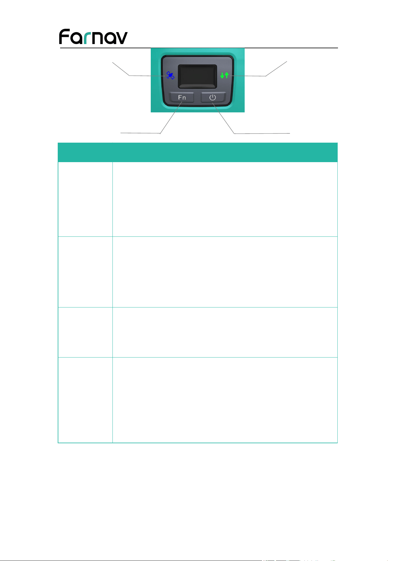
The following figure shows a front view of the receiver.
The front panel contains two indicator LEDs and 2 buttons.
Front panel
Correction LED
Farnav Nbase GNSS USER GUIDE
| 2026-02 P a g e | 7
Name
Description
Correction
LED (Orange/
Green)
Indicates whether the receiver is transmitting differential data.
The green LED flashes once per second when
As a Base station: successfully transmitting differential data.
As a Rover station: successfully receiving differential data from
Base station.
Satellite LED
(Blue)
Shows the number of satellites that the receiver has tracked.
When the receiver is searching satellites, the blue LED flashes once
every 5 seconds.
When the receiver has tracked N satellites, the blue LED will flash
N times every 5 seconds.
Fn button
Move to next line of the menus or options.
Move to next character of the value that you want to make change.
Cancel the change you make on a function.
Power button
Works as a Power button
Press and hold this button for 3 seconds to turn on or turn off the
receiver.
Works as a Confirm button
Hold Fn button and press this button for 5 times continuously to
reset the mainboard.
Power
Button
Satellite LED
Function button
Farnav Nbase GNSS USER GUIDE
| 2026-02 P a g e | 8
2.2.2 Lower housing and ports
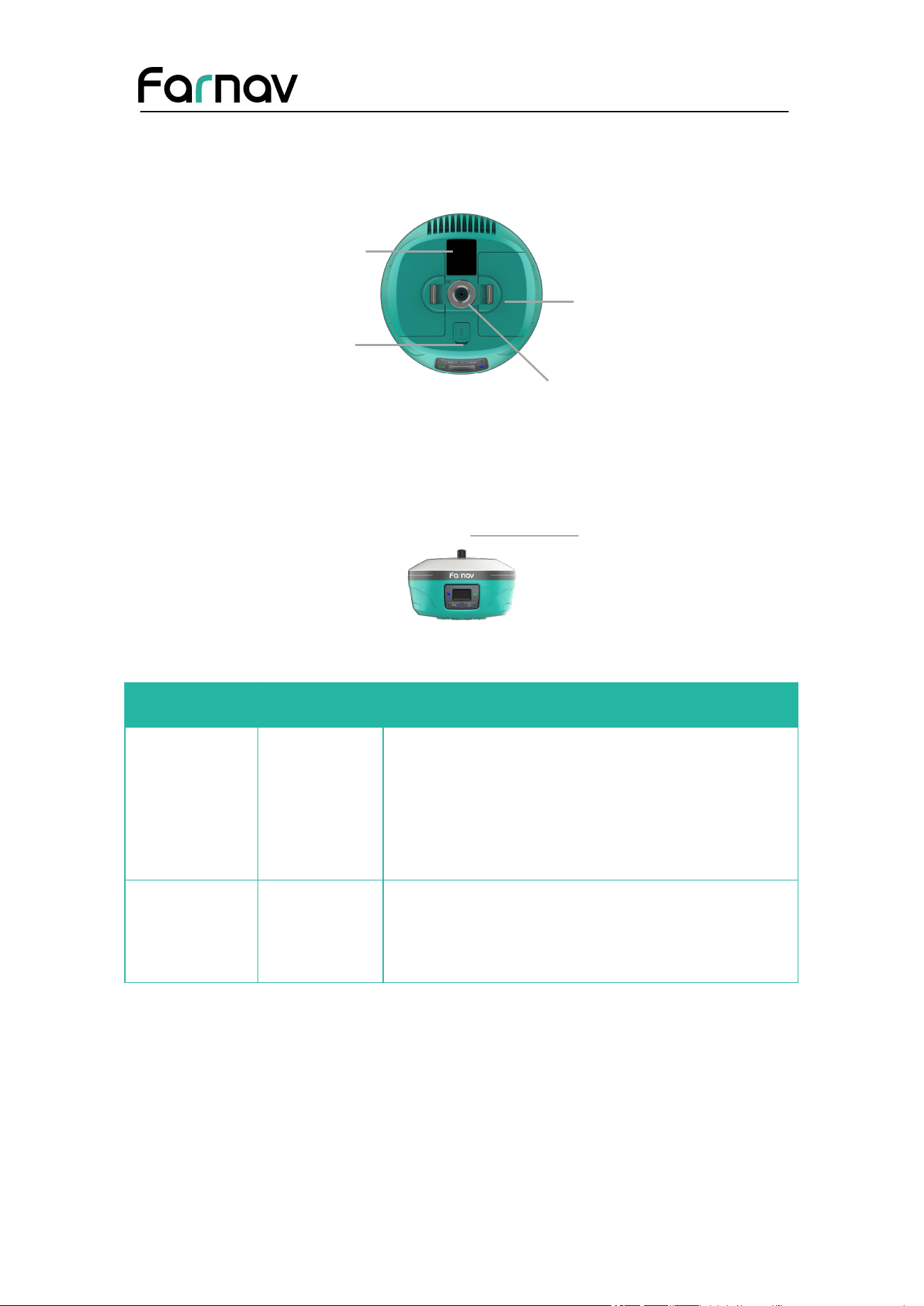
The lower housing contains one SIM card slot, two battery compartments, one
communication and power port, one 5/8-11 threaded insert, and one nameplate.
Port Name Description
IO port
This port is a 7-pin LEMO connector that
supports RS-232 communications.
Users can use a 7-pin cable to transmit
differential data to an external radio.
Radio antenna
connector
Connect a radio antenna to internal radio of the
receiver. And this connector is not used if you
are using an external radio.
Battery compartment
5/8-11 threaded
insert
IO serial communication
Nameplate
TNC radio antenna
Farnav Nbase GNSS USER GUIDE
| 2026-02 P a g e | 9
2.3 Batteries and Power
2.3.1 Internal Batteries
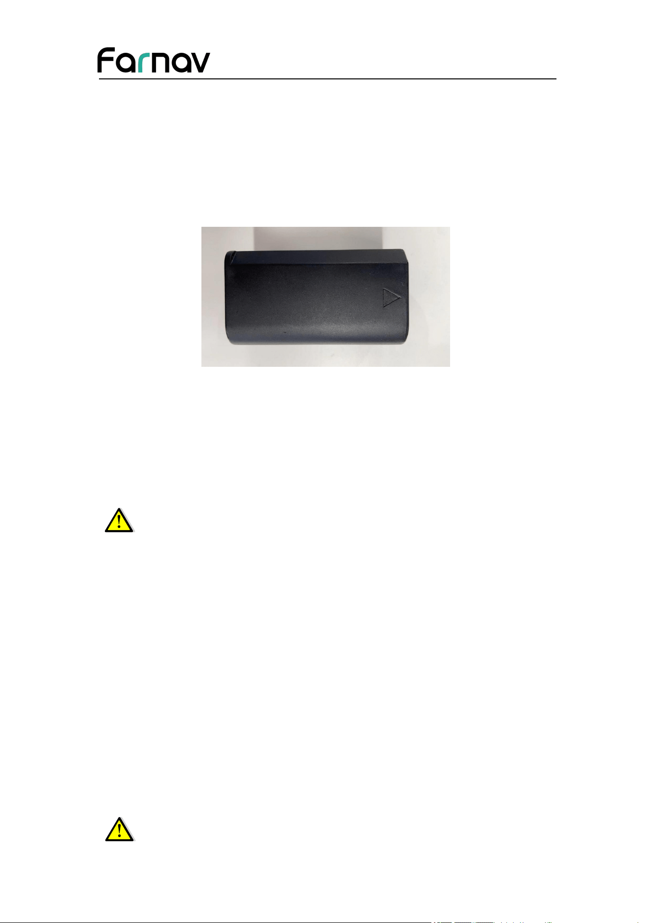
The receiver has two rechargeable Lithium-ion batteries, which can be removed for
charging.
2.3.2 Charging the Battery
The rechargeable Lithium-ion battery is supplied partially charged. Charge the battery
completely before using it for the first time. To charge the battery, first remove the
battery from the receiver, and then place it in the battery charger which is connected
to AC power.
WARNING – Charge and use the rechargeable Lithium-ion battery only in
strict accordance with the instructions. Charging or using the battery in
unauthorized equipment can cause an explosion or fire and can result in
personal injury and/or equipment damage.
To prevent injury or damage:
•Do not charge or use the battery if it appears to be damaged or leaking.
•Charge the Lithium-ion battery only in a EFIX product that is specified to charge it.
Be sure to follow all instructions that are provided with the battery charger.
•Discontinue charging a battery that gives off extreme heat or a burning odor.
•Use the battery only in EFIX equipment that is specified to use it.
•Use the battery only for its intended use and according to the instructions in the
product documentation.
2.3.3 Battery Safe
WARNING – Do not damage the rechargeable Lithium-ion battery. A
Farnav Nbase GNSS USER GUIDE
| 2026-02 P a g e | 10
damaged battery can cause an explosion or fire and can result in personal
injury and/or property damage.
To prevent injury or damage:
•Do not use or charge the battery if it appears to be damaged. Signs of damage include,
but are not limited to discoloration, warping, and leaking battery fluid.
•Do not expose the battery to fire, high temperature, or direct sunlight.
•Do not immerse the battery in water.
•Do not use or store the battery inside a vehicle under hot weather condition.
•Do not drop or puncture the battery.
•Do not open the battery or short-circuit its contacts.
WARNING – Avoid contact with the rechargeable Lithium-ion battery if it
appears to be leaking. Battery fluid is corrosive and contact with it can
result in personal injury and/or property damage.
To prevent injury or damage:
•If the battery leaks, avoid with the battery fluid.
•If battery fluid gets into your eyes, immediately rinses your eyes with clean water
and seek medical attention. Please do not rub your eyes!
•If battery fluid gets onto your skin or clothing, immediately use clean water to wash
off the battery fluid.
2.4 Inserting Battery and SIM Card
2.4.1 Inserting battery
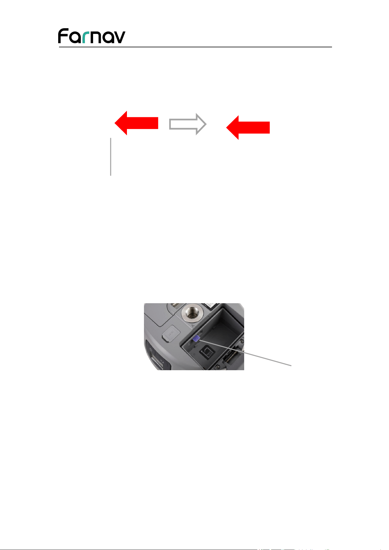
(a) Push down the spring-loaded button on the battery cover to open the cover.
(b) Put the battery into the Nbase slot, lock the battery as the picture shows like
below.
Farnav Nbase GNSS USER GUIDE
| 2026-02 P a g e | 11
Push back
Ba
t
tery cover
Lock the battery
(c) Close the battery cover to prevent water immersion.
(d) To remove the battery, unlock the battery from the slot first.
2.4.2 Inserting SIM card
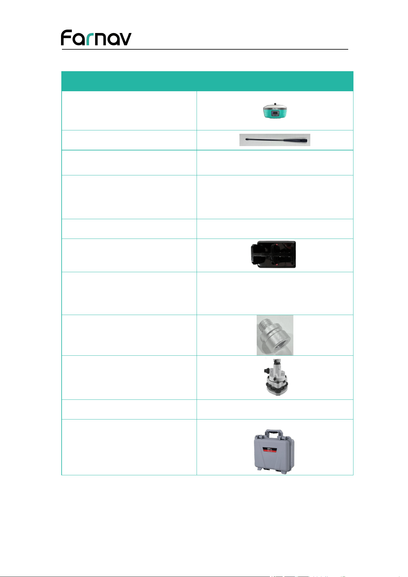
(a) Push down the spring-loaded button on the battery cover to open the cover.
(b) Insert the SIM card with the contacts facing downward, as indicated by the SIM
card icon on the battery slot.
(c) Close the battery cover to prevent water immersion.
(d) To eject the SIM card, slightly push it in to trigger the spring-loaded release
mechanism
Insert the SIM card with the contacts facing upward, as indicated by the SIM card
icon next to the SIM card slot.
To eject the SIM card, slightly push it in to trigger the spring-loaded release
mechanism.
Tip – The SIM card is provided by your cellular network service provider.
SIM slot
Farnav Nbase GNSS USER GUIDE
| 2026-02 P a g e | 12
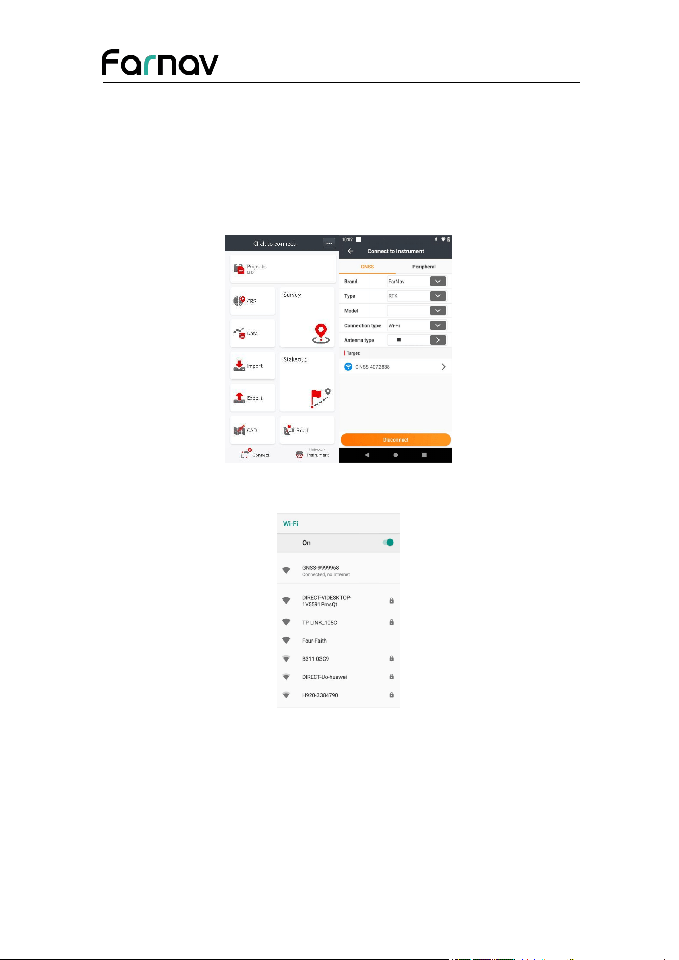
2.5 Product Basic Supply Accessories
Item
Picture
Nbase GNSS Receiver
UHF Bar Antenna (410-470 MHz)
Lithium Battery
H.I. Tape
Extension pole
C300 Pedestal charger
C300 Power Adapter with Cord
Tribrach adaptor
Tribrach with optical plummet
Auxiliary H.I. Tool
Transport Hard Case
Farnav Nbase GNSS USER GUIDE
| 2026-02 P a g e | 13
2.6 Connecting to a Controller
2.6.1 Connecting via Wi-Fi with eField Software
Turn on the controller → run eField → tap Connect.
In the Connect screen, select EFIX for the Brand field, Nbase for Model field, WIFI
for Contact type field.
Tap the WiFi icon to select the hot spot → Switch on the WiFi module by the top
switch → select the target device in the list.
Tap the Connect button to build the connection.
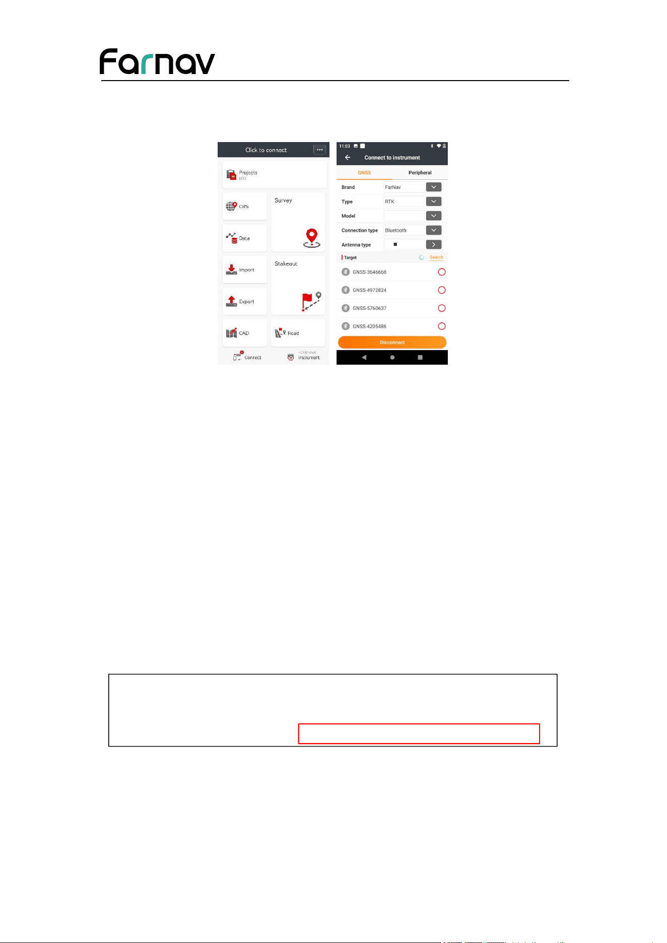
2.6.2 Connecting via Bluetooth with eField Software
Turn on the controller → run eField → tap Connect.
In the Connect screen, select EFIX for the Brand field, Nbase for Model field,
Bluetooth for Contact type field.
Farnav Nbase GNSS USER GUIDE
| 2026-02 P a g e | 14
Tap the Search icon and turn on the Bluetooth function to search Bluetooth device
around → select(pair) the target device in the list → Tap back button → select the
target device in the target list.
Tap the Connect button to build the connection.
2.7 Downloading Logged Data
Data logging involves the collection of GNSS measurement data over a period at a
static point or points, and subsequent post-processing of the information to accurately
compute baseline information. Data logging using receivers requires access to suitable
GNSS post-processing software such as the eOffice Software.
2.7.1 FTP Download
The procedures of downloading logged data through FTP are as follows:
(1) Switch on the receiver, search its Wi-Fi in the computer and connect.
(2) After the successful connection, open the file manager in the computer and input
“ftp://192.168.1.1” in the address box.
Farnav Nbase GNSS USER GUIDE
| 2026-02 P a g e | 15
(3) Input user name and password, the default user name and password are “ftp”.
(4) Double click the folder “repo_receiver SN” (take 3225804 as example), you will
see folders. The “push_log” folder is used to save the log files, and the "record_1"
folders are used for store static data.
(5) Double click the folder that you have configured to store the static data, you will
see the folder(s) created by the Nbase system automatically and named by the date
which is decide by GPS time when you start to log data.
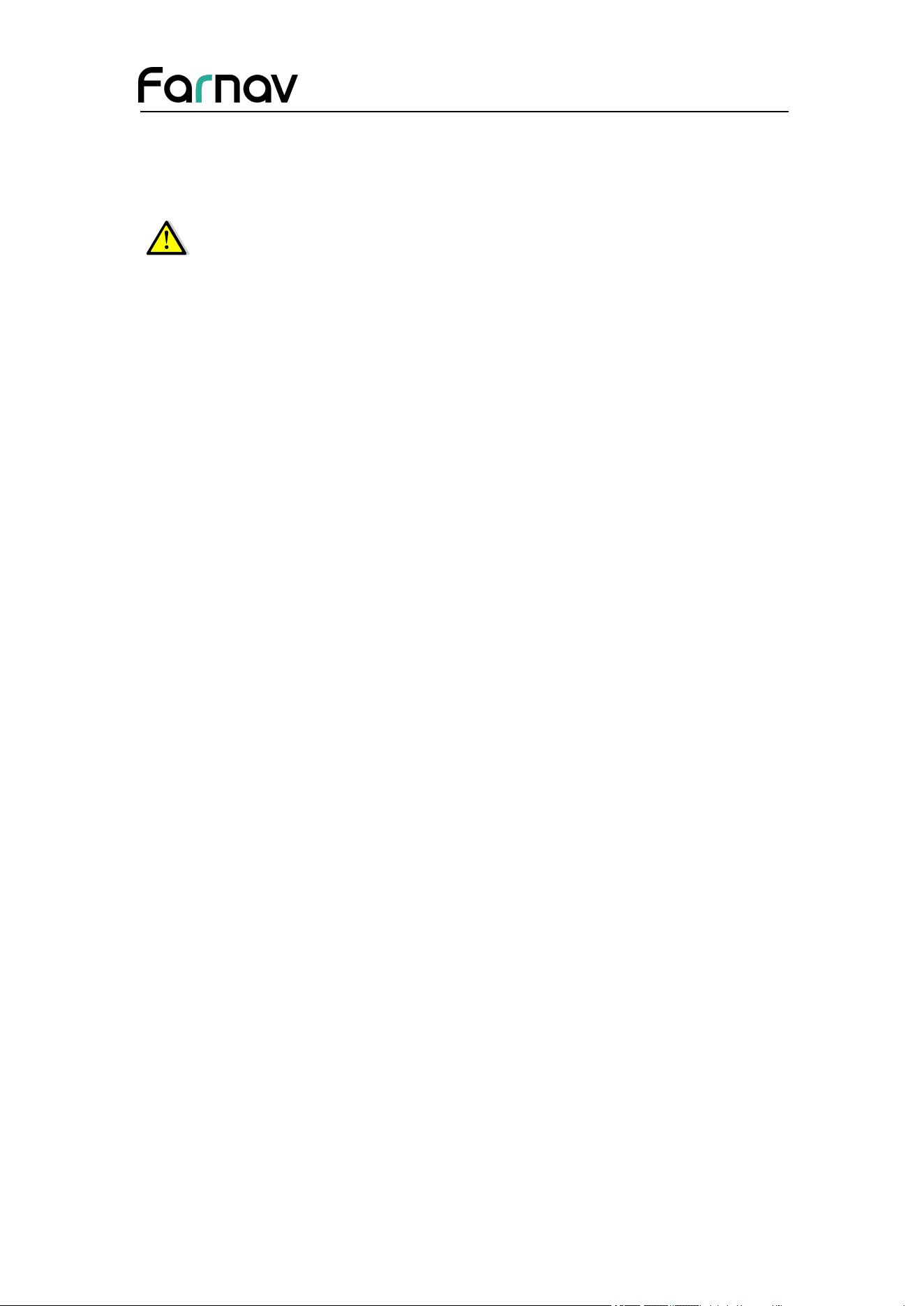
(6) Select the destination folder and double click it, two folders named as different
data format (ECN and rinex) will be displayed.
(7) Select the data format that you configured to save the static data, you will find the
static raw data.
Farnav Nbase GNSS USER GUIDE
| 2026-02 P a g e | 16
Notes: For ecn files, the name of the file is represented as XXXXXXDDDNN, where
XXXXXX is the SN of the receiver, DDD is day of year, and NN is the recording
session.
WARNING – The static data will be saved in the first logging session, the
“record_1” folder, by default. Old files will be deleted if the storage space is
full. If you configure not to auto delete old files when the memory is low, the
receiver will stop data logging.

Farnav Nbase GNSS USER GUIDE
| 2026-02 P a g e | 17
3 Front Panel Operation
The front panel contains one LCD screen, two indicator LEDs, and two buttons. The
operating controls are all located on the front panel.
3.1 Main Operation Menus
The top-level menu of the front panel includes 6 parts: Status, mode, static and info.
Status shows satellites, receiver solution and the power percentage. Mode is the
important part which illustrate the work mode and users can select the mode
according to their needs. Static is used to set static mode. Info is the basic information
of firmware such as SN, PN, etc.
The details of main operation are as follows and they are concluded two tables. The
first table includes 5 parts: Info, SV, Power, Data and Set and the second table
displays details of Data.
Top-level
Menu
Second-level Menu
Description
Status
Satellites
Indicate the total number of satellites
that have been tracked and the
number of satellites tracked of each
constellation, where G represents
GPS, R represents GLONASSS, C
represents BeiDou, S represents
SBAS, and E represents Galileo.
Power
Indicates the remaining power of the
battery inserted in the left (B) and
right (A) battery compartment.
WIFI ON/OFF
Press Enter to turn on or turn off
WIFI
Network status
displays the if a SIM card inserts the
RTK
Back
Press Enter to back to last page

Farnav Nbase GNSS USER GUIDE
| 2026-02 P a g e | 18
Mode
Ultra Base
Base External UHF
Base Internal UHF
Base APIS
Base External UHF & APIS
Rover APIS
Rover UHF
Rover NTRIP
Back
• Press Enter button to enter the
configuration screen of the selected
working mode.
• More operation information, see
3.2 Configure the Working Mode.
Static
Set on/off
Press Enter button to switch static
measurement on or off.
Recording
Display the time of recording
Advanced
Sample
Press Enter to change sample
interval (1s, 2s, 5s, 10s, 15s, 30s,
1m)
Elev Mask
degree
Press Enter button to change the
mask degree from 0 degree to 90
degrees.
Duration
• Press Enter button to enter
Duration Time Setting screen.
• In the Duration Time Setting
screen, press Fn button to move to
the character of the duration time
value user want to make change, and
then press Enter button to change
from 0 to 9. After the change has
been done, user can press Fn button
to move to OK field, and then Press
Enter button to save the change and
back to the second-level menu; or
press Fn button to move to Cancel
field and press Enter button to
cancel the change and back to the
second-level menu.
Measurement
phase Center
Press Enter button and switch height
between oblique, vertical, phase
center.
Antenna Height
Press Enter button and input the
measured antenna height.

Farnav Nbase GNSS USER GUIDE
| 2026-02 P a g e | 19
Back
Press Enter button to back to the last
menu.
OK
Press Enter to complete settings.
Back
Press Enter button to back to the
top-level menu.
Info
SN
PN
Register
Sleep Time
Version
IMEI
Language
Back
Describe the main information of
this machine. SN displays the Serial
Number of the receiver. PN displays
the Part Number of the receiver.
Register displays the expiry date of
registration code. Press Enter to
select sleep time including 5s, 10s,
30s, 1min, 30min. Version displays
the firmware version. IMEI is
International Mobile Equipment
Identity which is used to identify the
RTK. Press Enter to change
languages. Press back to go back to
the previous menu.
3.2 Configure the Working Mode
7 working modes are provided for quickly setting up an RTK base station or rover
station. Users can configure each working mode through the front panel as follows:
Top-level
Menu
Second-level Menu
Description
Ultra Base
/
Reserved for the Ultra Base mode.
Base External
UHF
Mode Base External UHF
The title of this configuration
screen.
Format
Press Enter to select correction
format (RTD, CMR, RTCMv2.3,
RTCMv3 and RTCMv3.2).
OK
Press Enter button to save the
settings and back to the top-level
menu, and then this working mode
can take effect.
Cancel
Press Enter button to cancel the
settings and back to the
second-level menu.
Base Internal
UHF
Mode Base External UHF
The title of this configuration
screen.

Farnav Nbase GNSS USER GUIDE
| 2026-02 P a g e | 20
Protocol
Press Enter to select current
protocol (EFIX, Transparent,
TT450s, Satel 3AS, EcoLink)
Channel
Press Enter to change the channel
Baud
Press Enter to select Baud (4800,
9600 and 19200)
Power
Press Enter button to change the
transmitting power (1w,2w,5w).
Format
Press Enter to select correction
format (RTD, CMR, RTCMv2.3,
RTCMv3 and RTCMv3.2).
OK
Press Enter button to save the
settings and back to the top-level
menu, and then this working mode
can take effect.
Cancel
Press Enter button to cancel the
settings and back to the
second-level menu.
Base APIS
Mode Base APIS
The title of this configuration
screen.
Format
Press Enter to select correction
format (RTD, CMR, RTCMv2.3,
RTCMv3 and RTCMv3.2).
IP
Press Enter to enter third-level
menu to select IP or press
Customized IP to customize your
own IP
Port
Press Enter button to change the
port from 9901 to 9920.
OK
Press Enter button to save the
settings and back to the top-level
menu, and then this working mode
can take effect.
Cancel
Press Enter button to cancel the
settings and back to the
second-level menu.
Base External
UHF & APIS
Mode Base External UHF
& APIS
The title of this configuration
screen.
Way External UHF+APIS
Display the way of base station

Farnav Nbase GNSS USER GUIDE
| 2026-02 P a g e | 21
combination.
Format
Press Enter to select correction
format (RTD, CMR, RTCMv2.3,
RTCMv3 and RTCMv3.2).
IP
Press Enter to enter third-level
menu to select IP or press
Customized IP to customize your
own IP
Port
Press Enter button to change the
port from 9901 to 9920.
OK
Press Enter button to save the
settings and back to the top-level
menu, and then this working mode
can take effect.
Cancel
Press Enter button to cancel the
settings and back to the
second-level menu.
Rover APIS
Mode Rover APIS
The title of this configuration
screen.
Base ID
Press Enter to enter third-level
menu to change Base ID
IP
Press Enter to enter third-level
menu to select IP or press
Customized IP to customize your
own IP
Port
Press Enter button to change the
port from 9901 to 9920.
OK
Press Enter button to save the
settings and back to the top-level
menu, and then this working mode
can take effect.
Cancel
Press Enter button to cancel the
settings and back to the
second-level menu.
Rover UHF
Mode Rover UHF
The title of this configuration
screen.
Protocol
Press Enter to select current
protocol (EFIX, Transparent,
TT450s, Satel 3AS, EcoLink)
Channel
Press Enter to change the channel
Baud
Press Enter to select Baud (4800,

Farnav Nbase GNSS USER GUIDE
| 2026-02 P a g e | 22
9600 and 19200)
OK
Press Enter button to save the
settings and back to the top-level
menu, and then this working mode
can take effect.
Cancel
Press Enter button to cancel the
settings and back to the
second-level menu.
Rover NTRIP
Mode Rover NTRIP
The title of this configuration
screen.
Status
Indicates the login status.
OK
Press Enter button to save the
settings and back to the top-level
menu, and then this working mode
can take effect.
Cancel
Press Enter button to cancel the
settings and back to the
second-level menu.
Back
Press Enter button to back to the
top-level menu.
Farnav Nbase GNSS USER GUIDE
| 2026-02 P a g e | 23
4 Equipment Setup and Operation
4.1 Post-processing Base Station Setup
For good performance, the following base station setup guidelines are recommended:
Components:
Steps:
(1)
Put tripod in the target position, center and level it roughly.
(2)
Place and lock the tribrach in the tripod.
(3)
Insert the batteries into the receiver.
(4)
Screw the receiver onto the extension pole, and connect it to Tribrach w/Opti.
(5)
Center and level the receiver more precisely.
No.
Name
a
Nbase GNSS receiver
b
Extension pole (30 cm)
c
Tribrach adaptor
d
Tribrach w/ Opti
e
Aluminum tripod
f
Lithium battery
a
b
d
e
c
f
Farnav Nbase GNSS USER GUIDE
| 2026-02 P a g e | 24
(6)
Connect the receiver to external battery by using external power cable if
necessary.
(7)
Connect the receiver to external storage disk by using USB cable if necessary.
(8)
Turn on the receiver by pressing the power button for 3s.
(9)
Measure the antenna height by using H.I. tape and auxiliary H.I. tool.
(10)
Press the function button to select Data to start recording static raw.
If work with a data controller:
(1)
Switch on the data controller and connect it to the receiver.
(2)
Use software to configure the receiver as static mode.
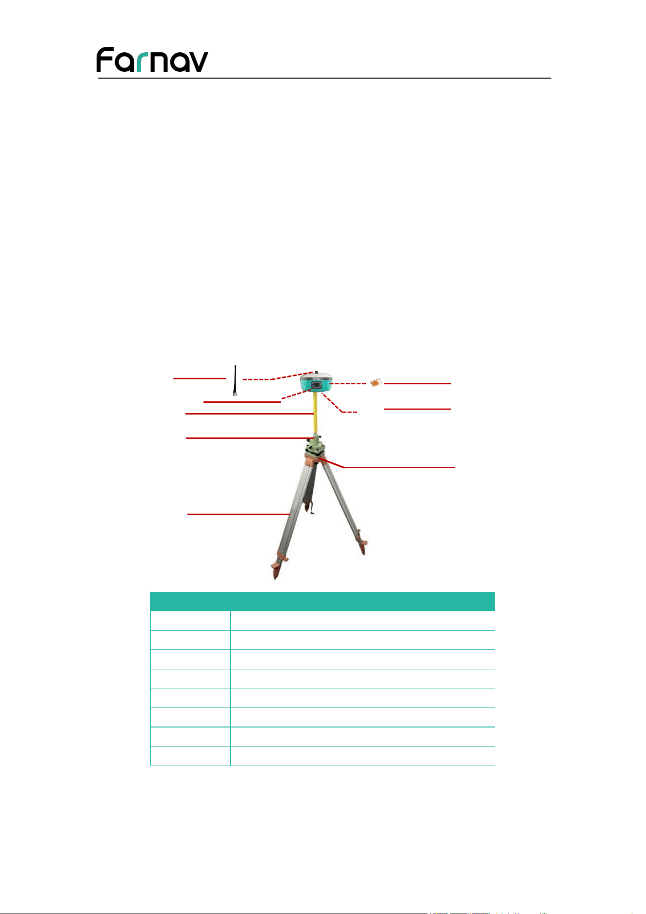
4.2 Real-Time Base Station
For good rover operation, the following base station setup guidelines are
recommended:
Components:
No.
Name
a
UHF whip antenna
b
Nbase GNSS receiver
c
Extension pole (30 cm)
d
Tribrach adaptor
e
Tribrach w/ Opti
f
Aluminum tripod
g
Nino SIM card (12 mm x 9 mm)
h
Lithium battery
a
b
d
e
c
g
h
f
Farnav Nbase GNSS USER GUIDE
| 2026-02 P a g e | 25
4.2.1 Real-Time Base Station Setup
Steps:
(1)
Put tripod in the target position, center and level it roughly.
(2)
Place and lock the tribrach in the tripod.
(3)
Insert the batteries into the receiver.
If work as a cellular base station, the SIM card need to be inserted before the
batteries.
(4)
Screw the receiver onto the tribrach.
(5)
Center and level the receiver more precisely.
If work as a UHF base station, the UHF whip antenna need to be connected to the
receiver.
(6)
Connect the receiver to external battery by using external power cable if
necessary.
(7)
Connect the receiver to external storage disk by using USB cable if necessary.
(8)
Turn on the receiver by pressing the power button for 3 s.
(9)
Measure the antenna height by using H.I. tape and auxiliary H.I. tool.
(10)
Switch on the data controller and connect it to the receiver.
(11)
Use software to configure the receiver as cellular base or UHF base mode.
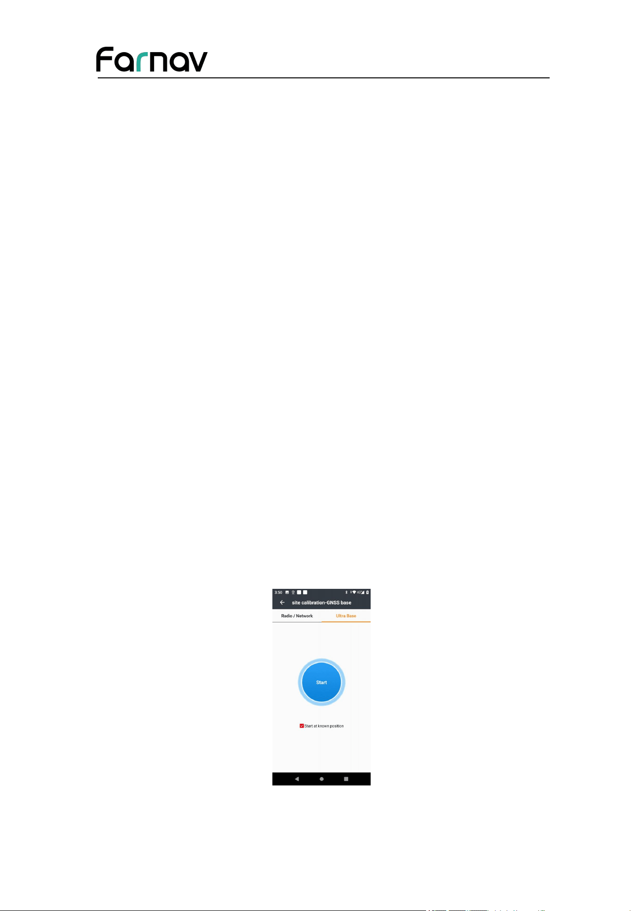
4.2.2 Ultra Base
Steps:
(1)
Connect to the receiver, locate GNSS Base in the Configure interface, and select
Ultra Base:
(2)
We can choose whether to start from a known position. Click the Start option to
initialize Ultra Base.
Farnav Nbase GNSS USER GUIDE
| 2026-02 P a g e | 26
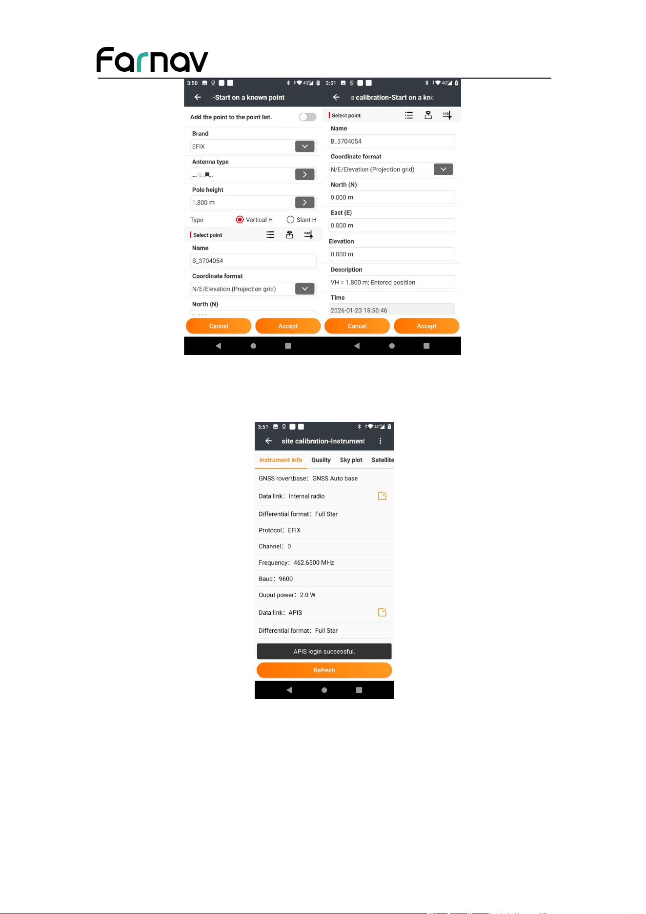
(3)
Upon the successful completion of the configuration, the operating mode of the
base station can be queried and verified in the Instrument Info option provides
access to comprehensive device details.
Farnav Nbase GNSS USER GUIDE
| 2026-02 P a g e | 27
4.3 Real-Time Rover Station
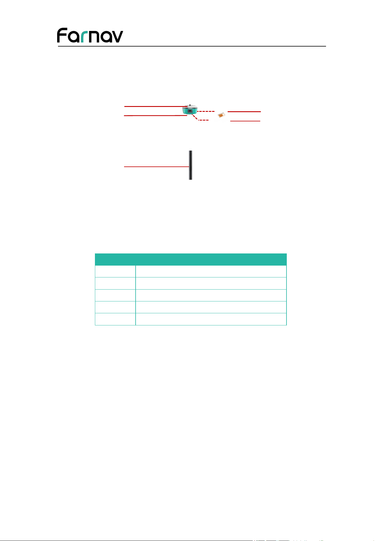
For good performance, the following rover station setup guidelines are recommended:
Components:
No.
Name
a
whip antenna
b
Nbase GNSS receiver
c
2M range pole w/bag
d
Micro SIM card (12 mm x 15 mm)
e
Lithium battery
4.3.1 Real-Time Rover Station Setup
Steps:
(1)
Insert the batteries into the receiver.
If work as a cellular rover station, the SIM card need to be inserted before the
batteries.
(2)
Screw the receiver onto the pole.
If work as a UHF rover station, the UHF whip antenna need to be connected to the
receiver.
(3)
Turn on the receiver by pressing the power button for 3 s.
(4)
Switch on the data controller and connect it to the receiver.
(5)
Use software to configure the receiver as cellular rover or UHF rover mode.
(6)
Center and level the receiver more precisely.
b
a
c
d
e
Farnav Nbase GNSS USER GUIDE
| 2026-02 P a g e | 28
(7)
Use software to start survey.
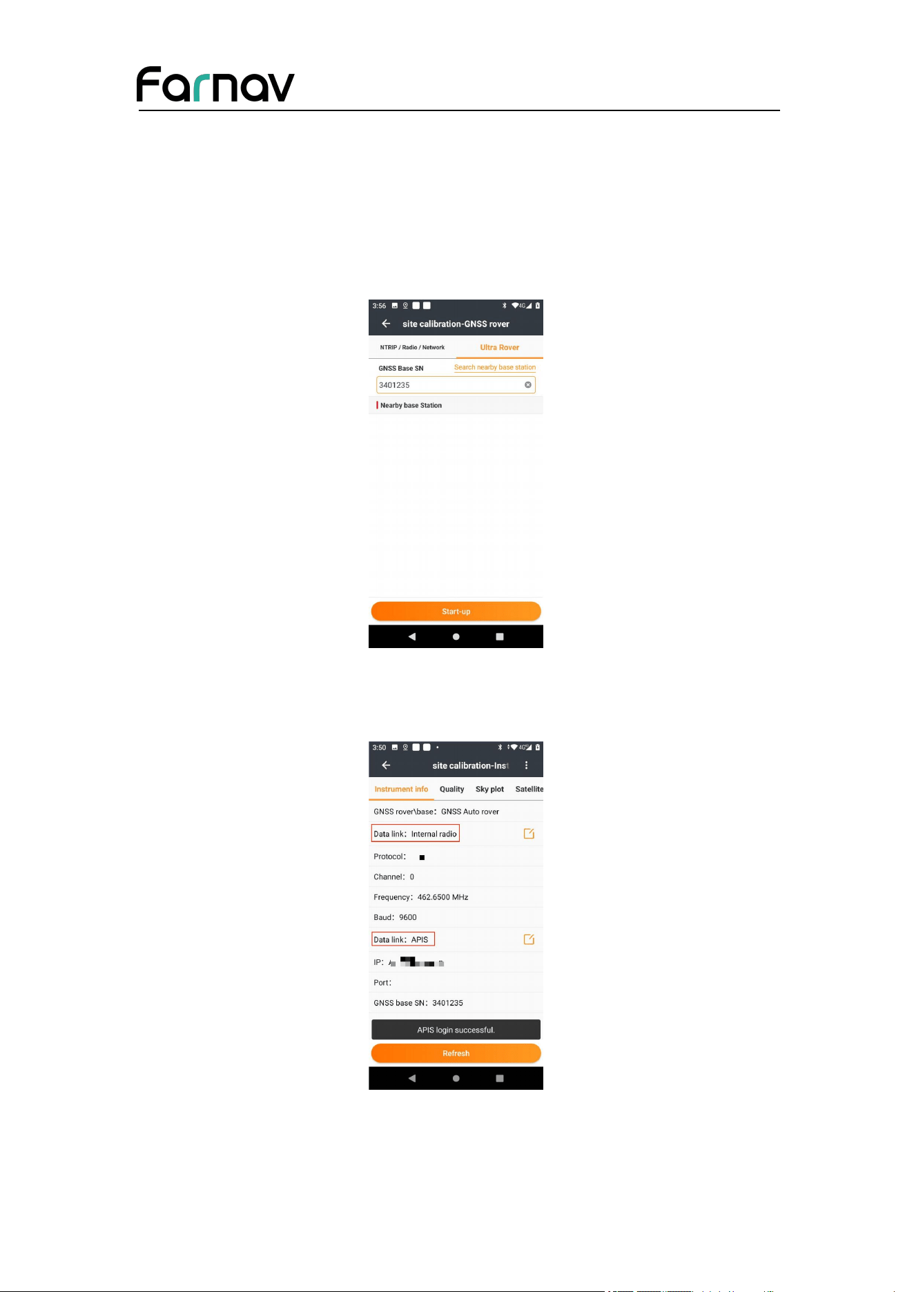
4.3.2 Ultra Rover
(1)Locate the GNSS Rover option in the Configure interface. In Ultra Rover, we can
receive the base station signal either by selecting the Nearby Base Station or entering
the Ultra Base serial number (SN).
(2)After completing the Ultra Rover configuration, the Instrument Info option
provides access to comprehensive device details, through which the active data link
can be verified and confirmed.
Farnav Nbase GNSS USER GUIDE
| 2026-02 P a g e | 29
5 Configuring Through a Web Browser
Supported browsers:
Google Chrome
Microsoft Internet Explorer version 10, or higher
To connect to the receiver through a web browser:
1. Turn on the Wi-Fi of the receiver.
2. Search the wireless network named as GNSS-XXXXXXX (the SN of your
receiver) on your computer, and then establish the connection.
3. After the successful connection between your computer and the receiver, enter
the IP address (192.168.1.1) of the receiver into the address bar of the web
browser on your computer:
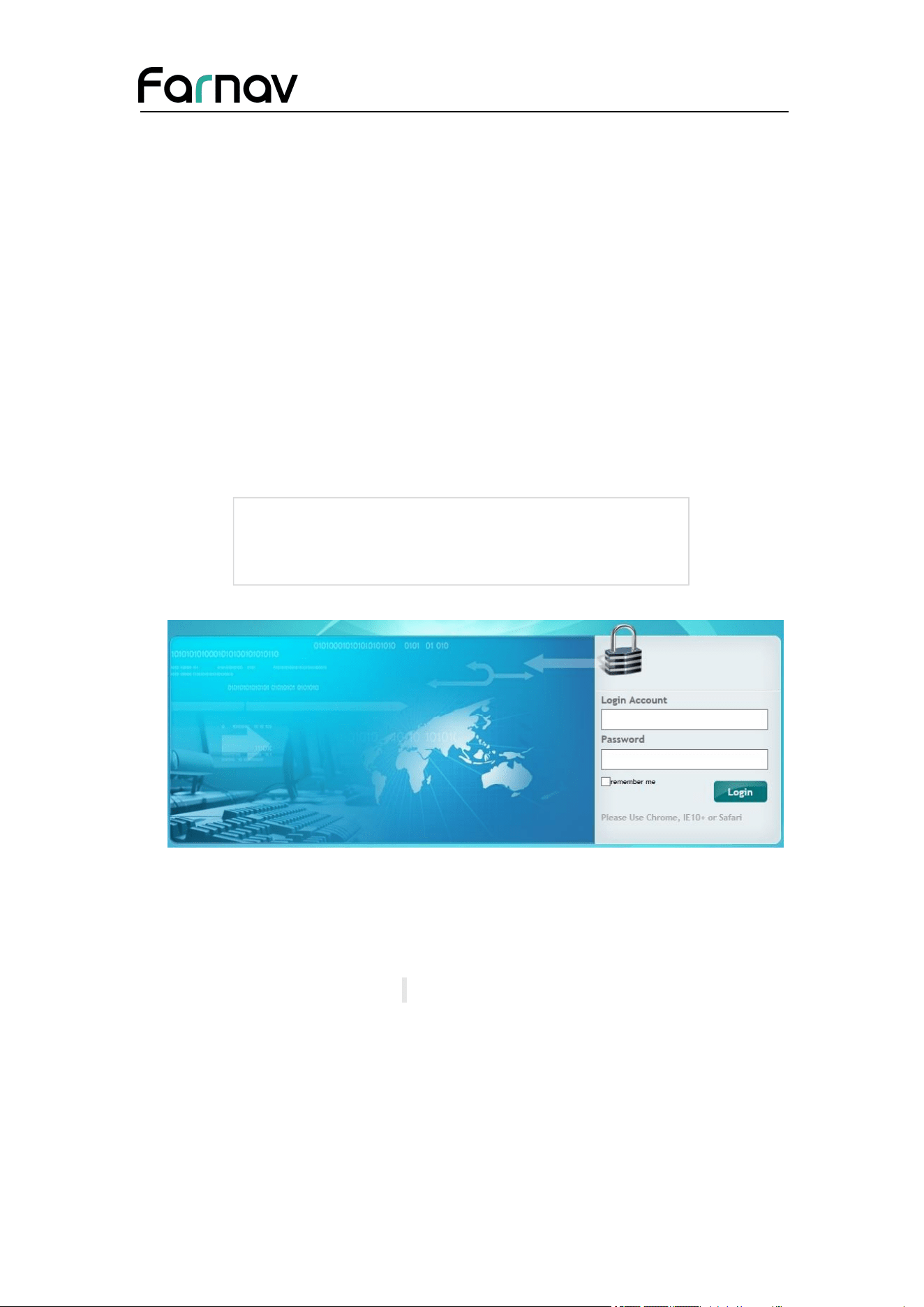
4. The web browser prompts you to enter a login account and password:
The default login account for the receiver is:
Login Account: admin
Password: password
Note – Tick remember me option, and then the browser will remember the Login
Account and Password you entered.
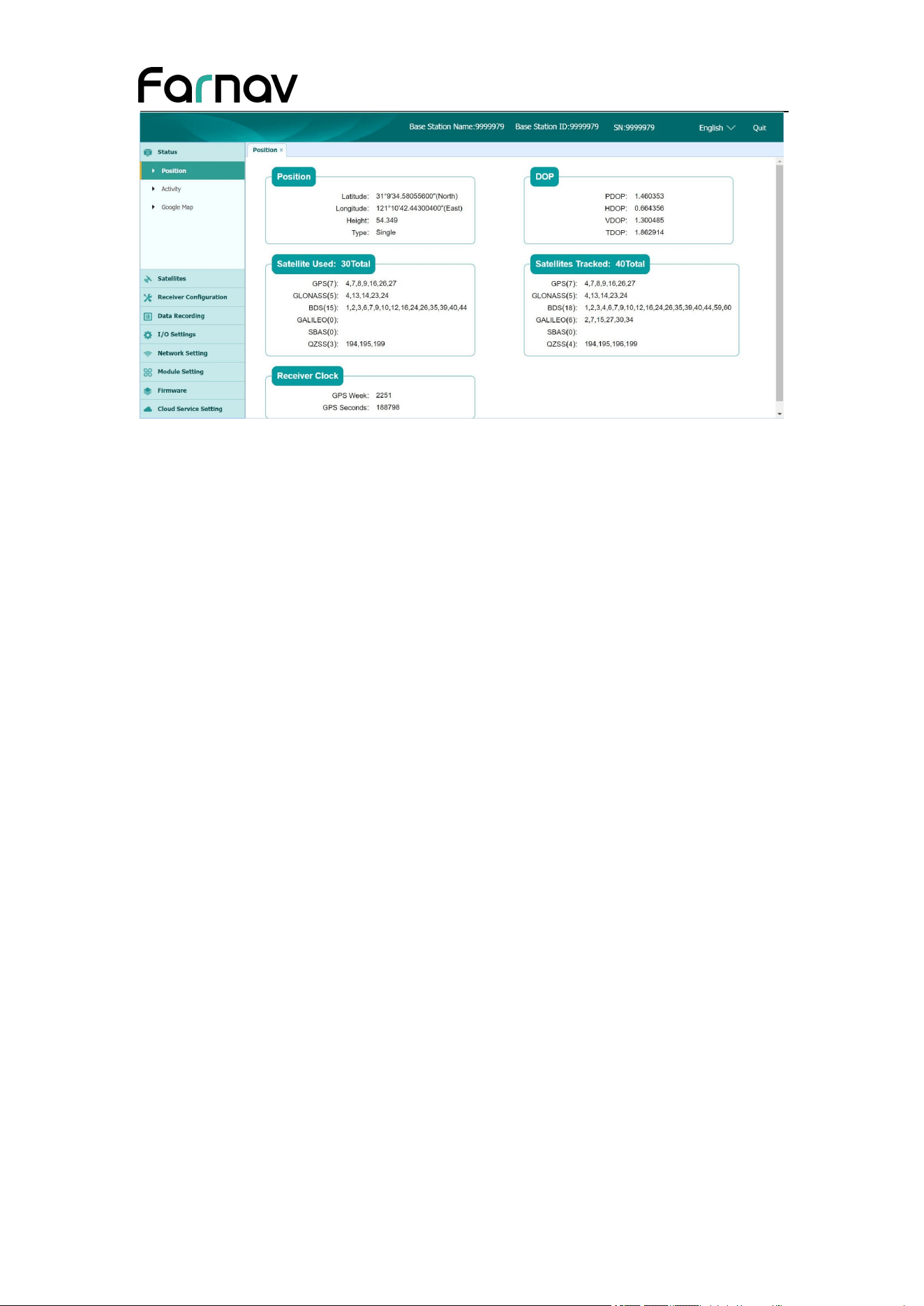
5. Once you log in, the web page appears as follows:
Farnav Nbase GNSS USER GUIDE
| 2026-02 P a g e | 30
This web page shows the configuration menus on the left of the browser window, and
the setting on the right. Each configuration menu contains the related Submenus to
configure the receiver and monitor receiver performance.
This chapter describes each configuration menu.
To view the web page in another language, select the corresponding language name
from the dropdown list on the upper right corner of the web page.
Currently, these languages are available:
5.1 Status Menu
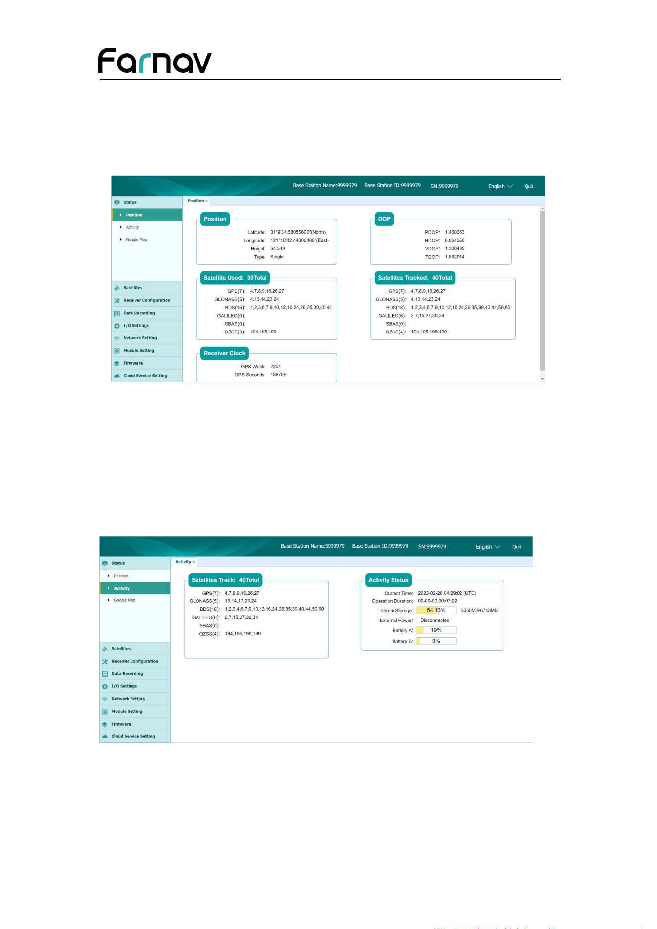
This menu provides a quick link to review the receiver's position information,
satellites tracked, runtime, current data log status, current outputs, available memory,
and more.
Farnav Nbase GNSS USER GUIDE
| 2026-02 P a g e | 31
5.1.1 Position Submenu
This page shows the relevant position information about the receiver's position
solution which including the position, DOP values, satellites used and tracked, and the
receiver clock information.
5.1.2 Activity Submenu
Lists several important items to help you understand how the receiver is being used
and its current operating condition. Items include the identities of currently tracked
satellites, internal and external storage usage rate, how long the receiver has been
operational, state of the internal battery, power source state. With this information, it
is easy to tell exactly what functions the receiver is performing:
Farnav Nbase GNSS USER GUIDE
| 2026-02 P a g e | 32
5.1.3 Google Map Submenu
Tap this submenu to show the location of the receiver on Google map.
5.2 Satellites Menu
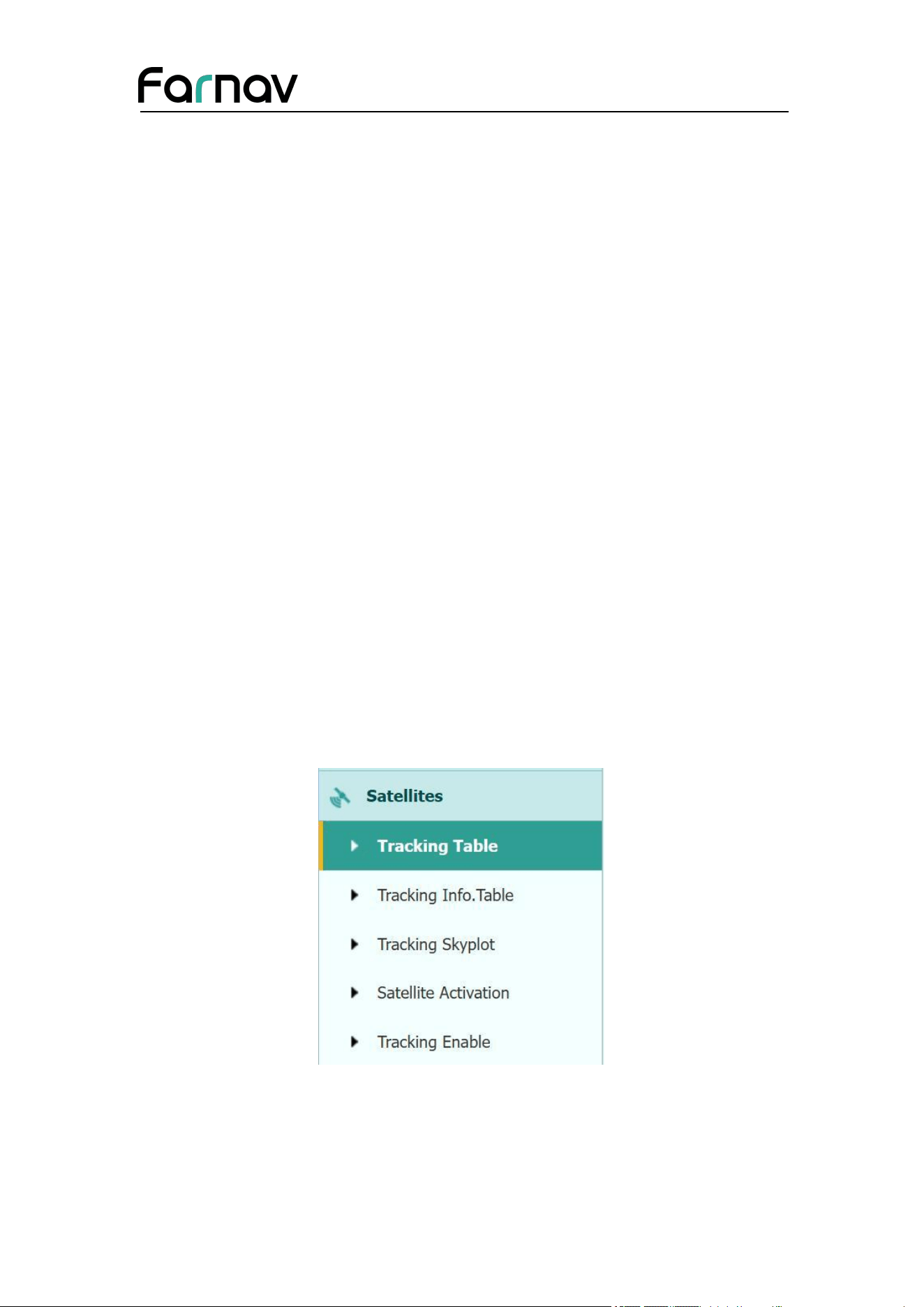
Use the Satellites menu to view satellite tracking details and enable/disable GPS,
GLONASS, BDS and Galileo constellations. These menus include tabular and
graphical displays to provide all required information on satellite tracking status.
Farnav Nbase GNSS USER GUIDE
| 2026-02 P a g e | 33
5.2.1 Tracking Table Submenu
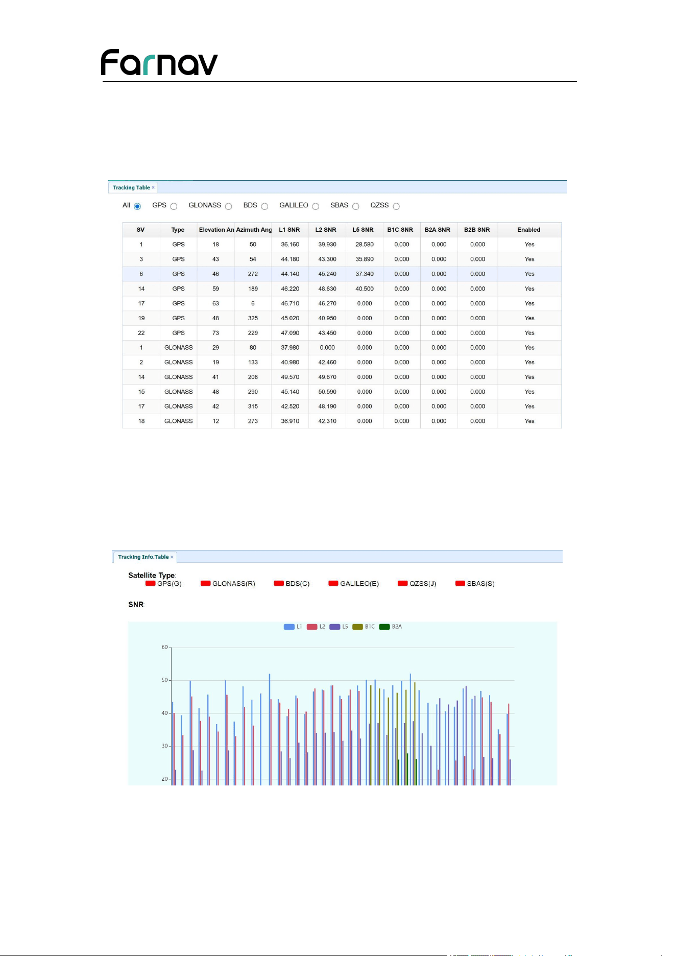
Provides the status of satellites tracked in general, such as the satellite ID, satellite
type, attitude angle, azimuth angle, L1 SNR, L2 SNR, L5 SNR B1C SNR, B2A SNR,
B2B SNR and enable/disable status of each one.
5.2.2 Tracking Info. Table Submenu
The following figure is an example of satellite track diagram page. Users can
determine the satellite types and the corresponding SNR of L-band carriers to be
displayed in any combination.
Farnav Nbase GNSS USER GUIDE
| 2026-02 P a g e | 34
5.2.3 Tracking Skyplot Submenu
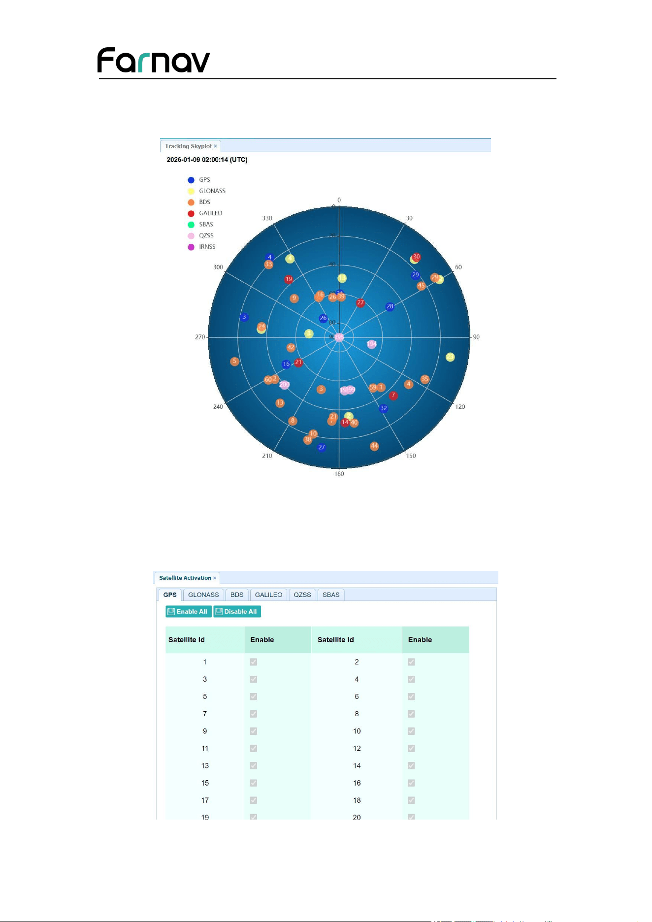
The following figure is an example of Skyplot page.
5.2.4 Satellite Activation Submenu
Use this menu to enable or disable satellites.

Farnav Nbase GNSS USER GUIDE
| 2026-02 P a g e | 35
5.2.5 Tracking Enable Submenu
Use this menu to enable or disable satellite tracks.
5.3 Receiver Configuration Menu
Use this menu to configure settings such as the antenna type and height, elevation
mask and PDOP setting, the reference station coordinates, receiver resetting and web
interface language:
Farnav Nbase GNSS USER GUIDE
| 2026-02 P a g e | 36
5.3.1 Description
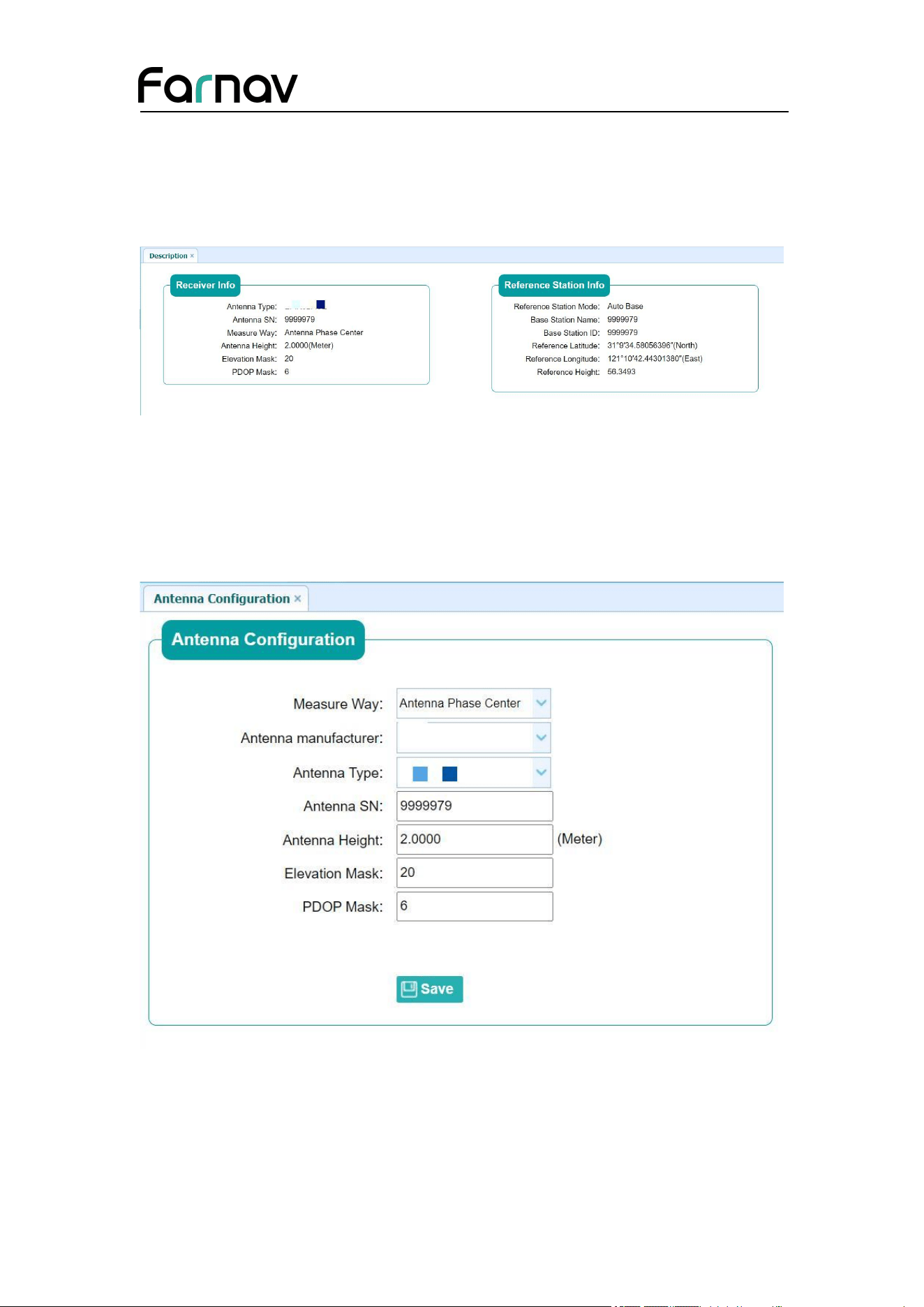
This submenu shows the receiver information and reference station information,
including antenna related information, elevation mask angle, reference station work
mode and position, etc.
5.3.2 Antenna Configuration Submenu
Use this screen to configure all the items related to the GNSS antenna. You must enter
the correct values for all antenna-related fields, because the choices you make affect
the accuracy for logged data and broadcast correction data significantly:
Farnav Nbase GNSS USER GUIDE
| 2026-02 P a g e | 37
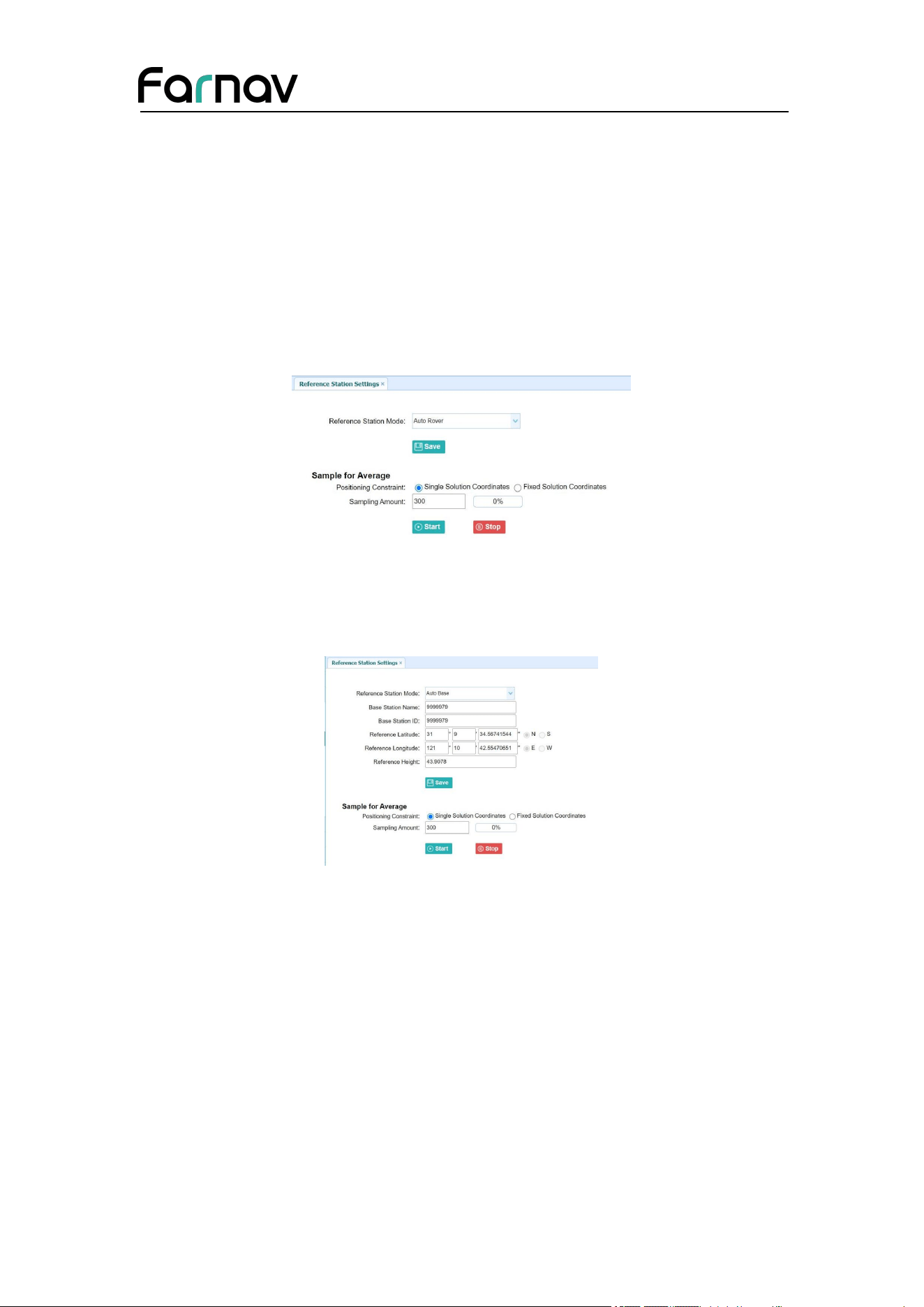
5.3.3 Reference Station Settings Submenu
Use this screen to configure settings such as the station coordinates and the broadcast
station identifiers. You must enter accurate information in these fields, as this data
affects the accuracy of logged data files and broadcast correction data significantly:
For Reference Station Mode:
There are three modes available:
a) Auto Rover: The receiver will serve as a rover after this mode is enabled, and
then receive correction data through the working mode set last time.
b) Auto Base: The receiver will serve as a base after this mode is enabled, and
then broadcast correction data based on coordinate inputted by user or
obtained through autonomous positioning automatically.
c) Manual Base: The receiver will serve neither as a base nor a rover after this
mode is enabled. Users need to configure the receiver manually.
Farnav Nbase GNSS USER GUIDE
| 2026-02 P a g e | 38
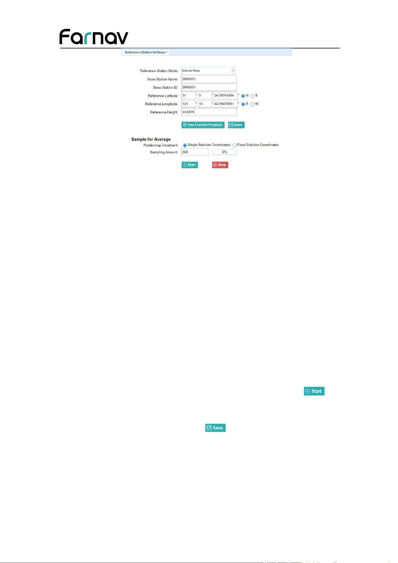
For Reference Latitude and Reference Longitude:
There are mainly three methods to enter the reference coordinates and shown as
follows:
a) Acquire Current Position: Click this button to acquire current position
obtained through autonomous positioning automatically.
b) Manual Input: Manually input the coordinate of a control point.
c) From CORS: After the receiver logging in CORS, the software can record the
coordinate of current position based on fix solution.
For Sample for Average:
Users can determine the positioning limit and sampling amount. The positioning limit
falls into two types:
a) Single Solution Coordinates: Collect the coordinates of receiver obtained
through autonomous positioning.
b) Fixed Solution Coordinates: Only collect coordinates of receiver with a fixed
solution.
After the configuration of positioning limit and sampling amount, click to
carry out sampling and averaging → the progress bar will show the progress → the
result will be served as the coordinate of current position.
If users need to save the changes, please tap button.
5.3.4 Receiver Reset Submenu
Use this screen to completely or partially reset the receiver:
Farnav Nbase GNSS USER GUIDE
| 2026-02 P a g e | 39
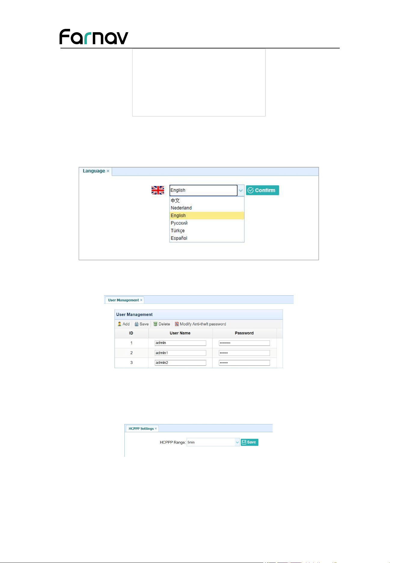
5.3.5 Languages Submenu
Use this screen to select the web interface language:
5.3.6 User Management Submenu
5.3.7 HCPPP Settings
Reserved menu.
5.4 Data Recording Menu
Use the Data Logging menu to set up the receiver to log static GNSS data and to view
the logging settings. You can configure settings such as observable rate, recording rate,
Farnav Nbase GNSS USER GUIDE
| 2026-02 P a g e | 40
continuous logging limit, and whether to auto delete old files when memory is low.
This menu also provides the controls for the FTP push feature:
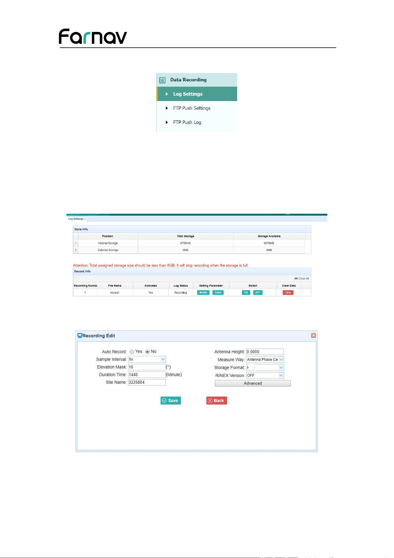
5.4.1 Log Settings Submenu
Here shows the data logging status, including internal and external storage usage and
data logging status of each session. Also, users can configure the data logging settings
for each session, including recording name, store location, storage limit, store formats,
start time, etc.
To edit the settings of each session, click the Modify button to the right of the
required session, and then the Recording Edit screen appears:
Click advanced to see more settings.
Farnav Nbase GNSS USER GUIDE
| 2026-02 P a g e | 41
In this screen, you can configure all the data logging parameters, and determine
whether the recording files will be affected by the FTP Push. The parameters are
mainly as follows:
Auto Record: on or off.
Sample Interval: Select the observable rate from the dropdown list.
Elevation Mask: Enter the elevation mask.
Duration Time: Set the duration of data logging.
Site Name: Enter the name of the site.
Antenna Height: the measured height value.
Measure way: Antenna Phase Center, Vertical Height, Slant Height
Storage Format: Select the format of the data store.
RINEX Version: OFF, 3.02, 2.11
Start Date: Select Yes or No option to determine whether to auto record start
date.
Apply Time: Select Yes or No option to determine whether to auto record
apply time.
Integral Point Store: Select Yes or No option to determine whether to allow
receiver to save data every hour.
Circulating Memory: Select Yes or No option to determine whether to auto
delete old files if the storage space is full.
Repeat Observations: Select Yes or No option to determine whether to turn
on to record a single observation.
Store Location: Internal Storage, External Storage.
Assigned Storage: The assigned memory size of current thread(for example,
Record 1) is 10000MB
Observer: Enter the name of observer.
Observer Agency: Enter the name of observer agency.
FTP Push: Decide whether to push the stored files to the FTP server of your
choice.
Tap button to save the settings and back to the Log Settings screen. Also,
users can click to abandon the changed settings and back to Log Settings
screen.
Farnav Nbase GNSS USER GUIDE
| 2026-02 P a g e | 42
Note – To modify data logging parameters, make sure the data logging session is
switched off.
To switch on or off ANY data logging session, tap the ON or OFF button on the right
of the required session.
To delete the recorded files of ANY data logging session, tap the Clear button on the
right of the required session.
To delete the recorded files of ALL data logging sessions, tap the Clear ALL
Accounts button.
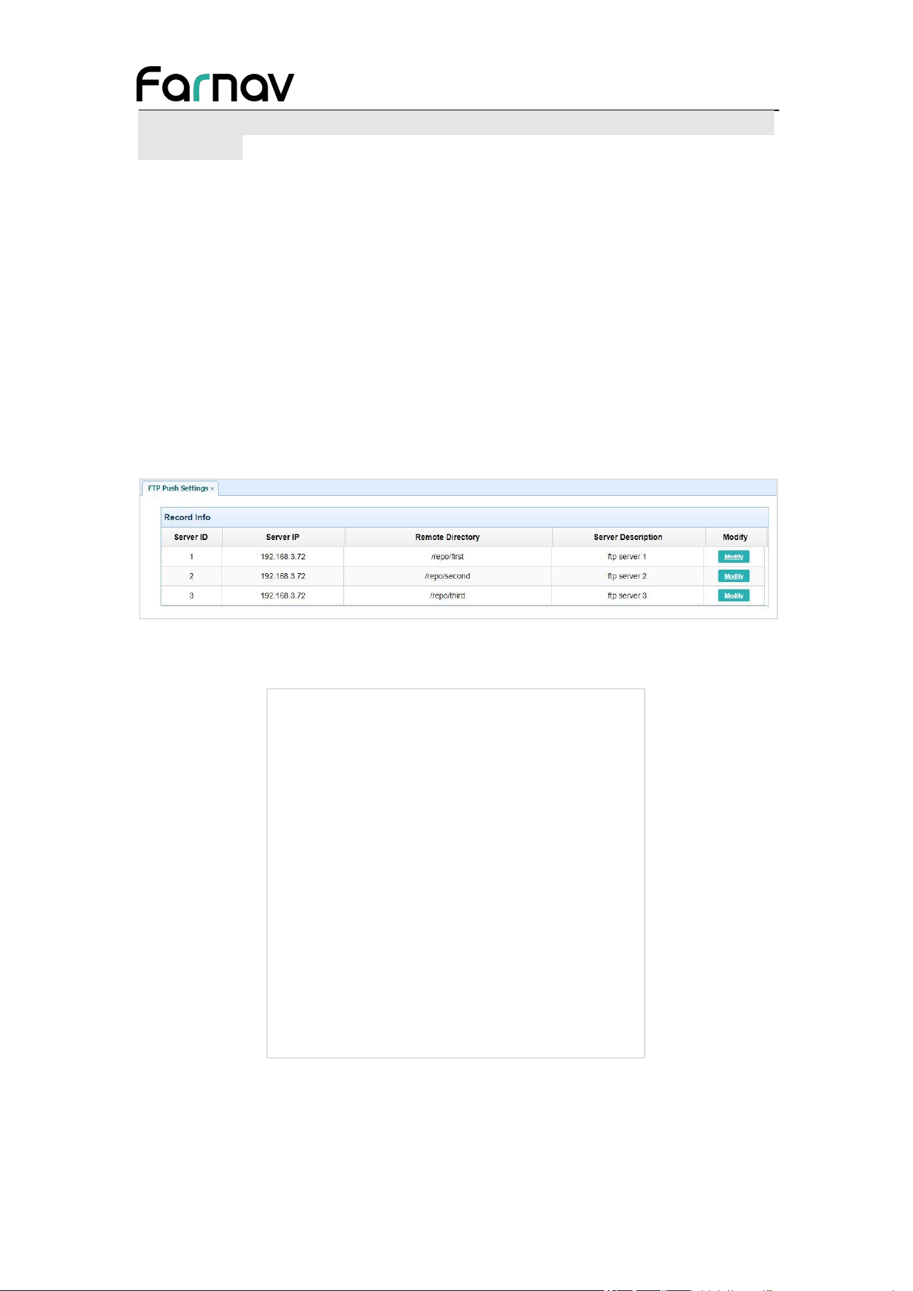
5.4.2 FTP Push Settings Submenu
Use this screen to configure the receiver to push stored files to the FTP server of your
choice. Only files that are configured to use FTP push are transmitted.
Tap Modify button on the right of the required FTP server and the FTP Push Settings
screen appears:
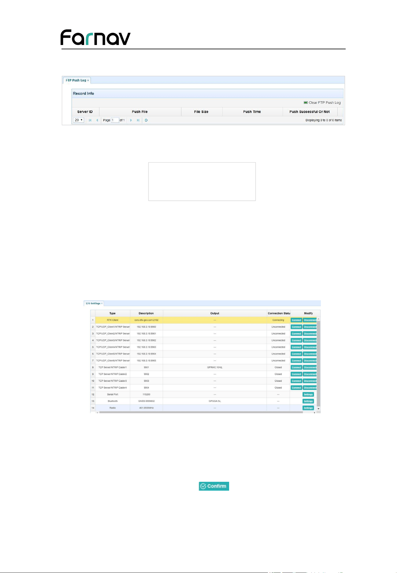
5.4.3 FTP Push Log Submenu
Shows the related information about the recorded filed that be pushed. And users can
Farnav Nbase GNSS USER GUIDE
| 2026-02 P a g e | 43
tap Clear Ftp Send Log button in the upper right corner to clear the log of FTP Push
operations.
5.5 IO Settings Menu
Use the IO Settings menu to set up all receiver outputs and inputs. The receiver can
output CMR, RTCM, Raw data, Ephemeris data, GPGGA, GPGSV, on TCP/IP, UDP,
serial port, or Bluetooth ports.
5.5.1 IO Settings Submenu
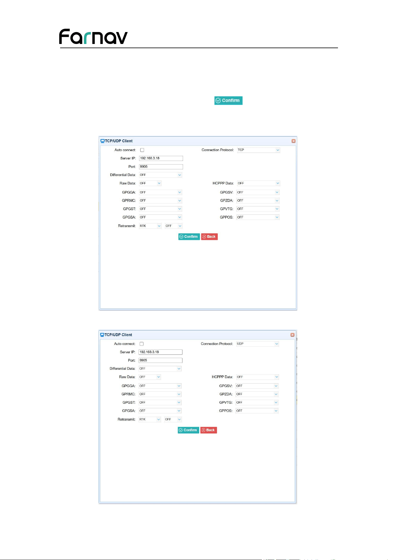
The following figure shows an example of the screen that appears when you select
this submenu. (Serial port setting is reserved menu)
In this submenu, users can configure 6 types of input and output settings.
1. RTK Client
After configuring the settings of RTK client, users can log on CORS or APIS. Tap the
Connect button to the right → the IO Settings screen will appear → choose one of the
connection protocols among the NTRIP, APIS_BASE, APIS_ROVER and TCP →
configure the related parameters → click to log on CORS or APIS.
Connection Protocol: NTRIP

Farnav Nbase GNSS USER GUIDE
| 2026-02 P a g e | 44
Connection Protocol: APIS_BASE
Connection Protocol: APIS_ROVER
Connection Protocol: TCP
Farnav Nbase GNSS USER GUIDE
| 2026-02 P a g e | 45
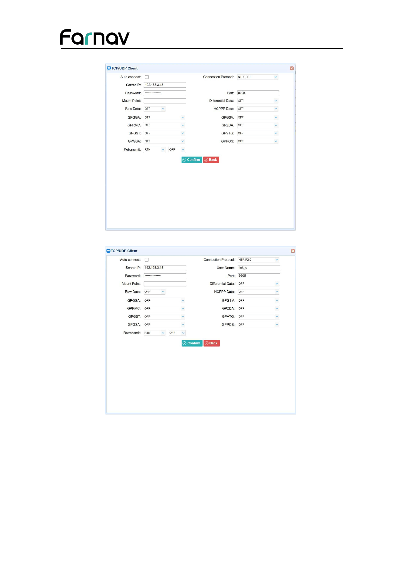
2. TCP/UDP_Client/NTRIP Server
Tap the Connect button on the right of required TCP/UDP Client → the IO Settings
screen will appear → select the connection protocol from TCP, UDP, NTRIP1.0 and
NTRIP2.0 → enter the IP and Port of the target server → configure messages that you
want to output to the target server → click to save and complete the
connection.
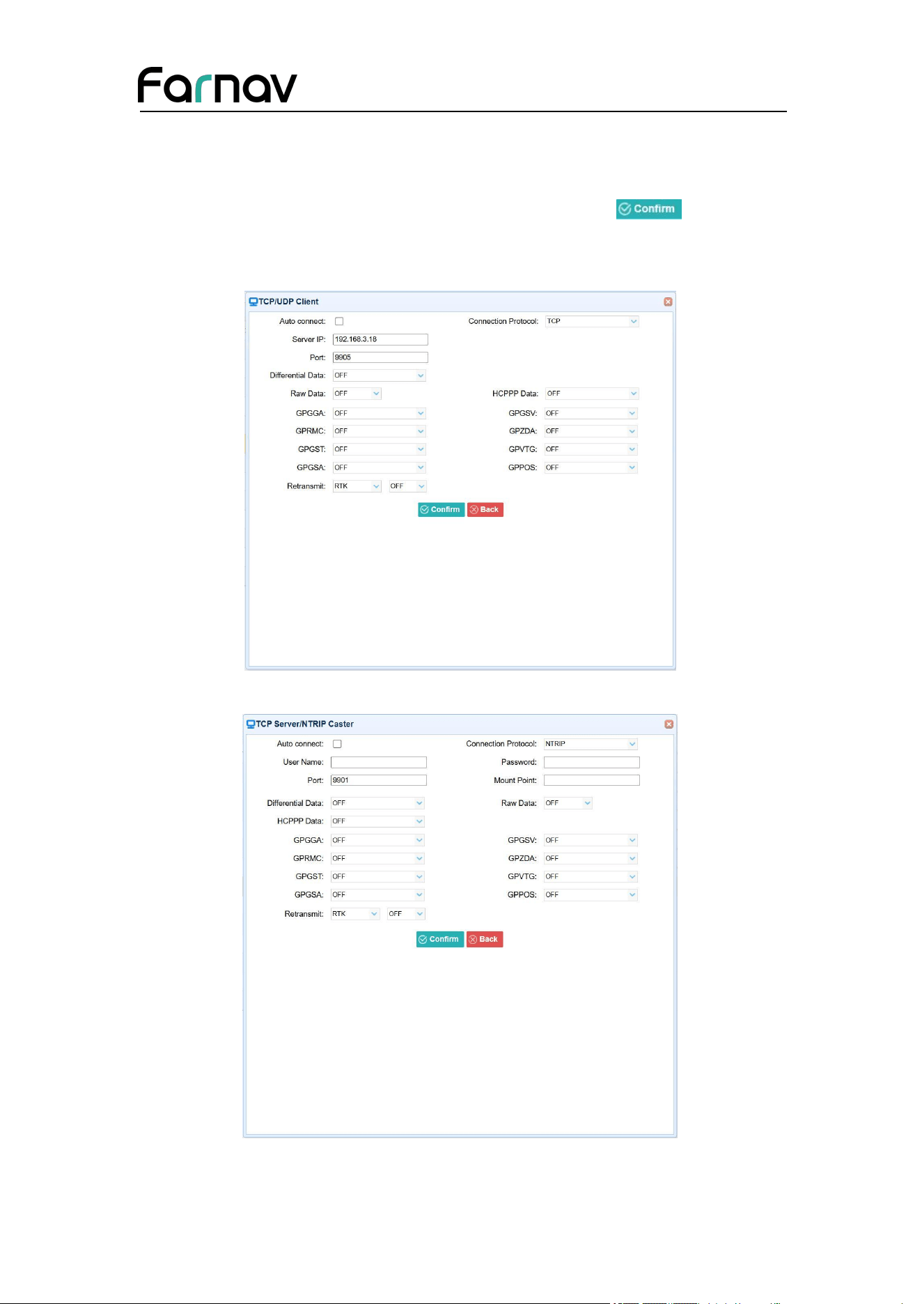
Connection Protocol: TCP
Connection Protocol: UDP
Farnav Nbase GNSS USER GUIDE
| 2026-02 P a g e | 46
Connection Protocol: NTRIP1.0
Connection Protocol: NTRIP2.0
Farnav Nbase GNSS USER GUIDE
| 2026-02 P a g e | 47
3. TCP Server/NTRIP Caster
Tap the Connect button to the right of required TCP Server/NTRIP Caster→ the IO
Settings screen will appear → select one of the connection protocols between NTRIP
and TCP → configure the other related parameters → click to save the
settings and open the server.
Connection Protocol: TCP
Connection Protocol: NTRIP
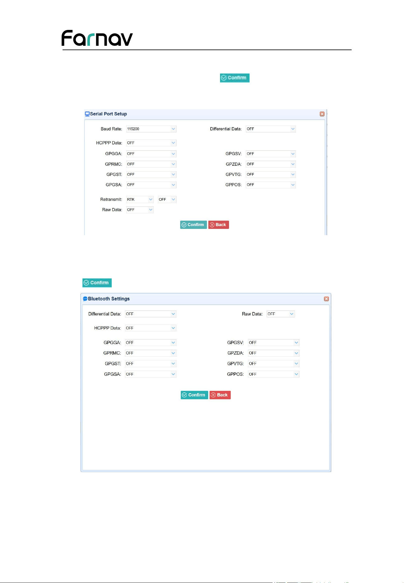
4. Serial Port
Farnav Nbase GNSS USER GUIDE
| 2026-02 P a g e | 48
Tap the Settings button on the right of Serial Port → the Serial Port Setup screen will
appear → select Baud Rate used to transmit data → configure the messages that you
want to output through the serial port → click to save the settings and start
to transmit.
5. Bluetooth
Tap the Settings button to the right of Bluetooth → the Bluetooth Set screen will
appear → configure the messages that you want to transmit through Bluetooth →
click to save the settings and start to transmit.
Farnav Nbase GNSS USER GUIDE
| 2026-02 P a g e | 49
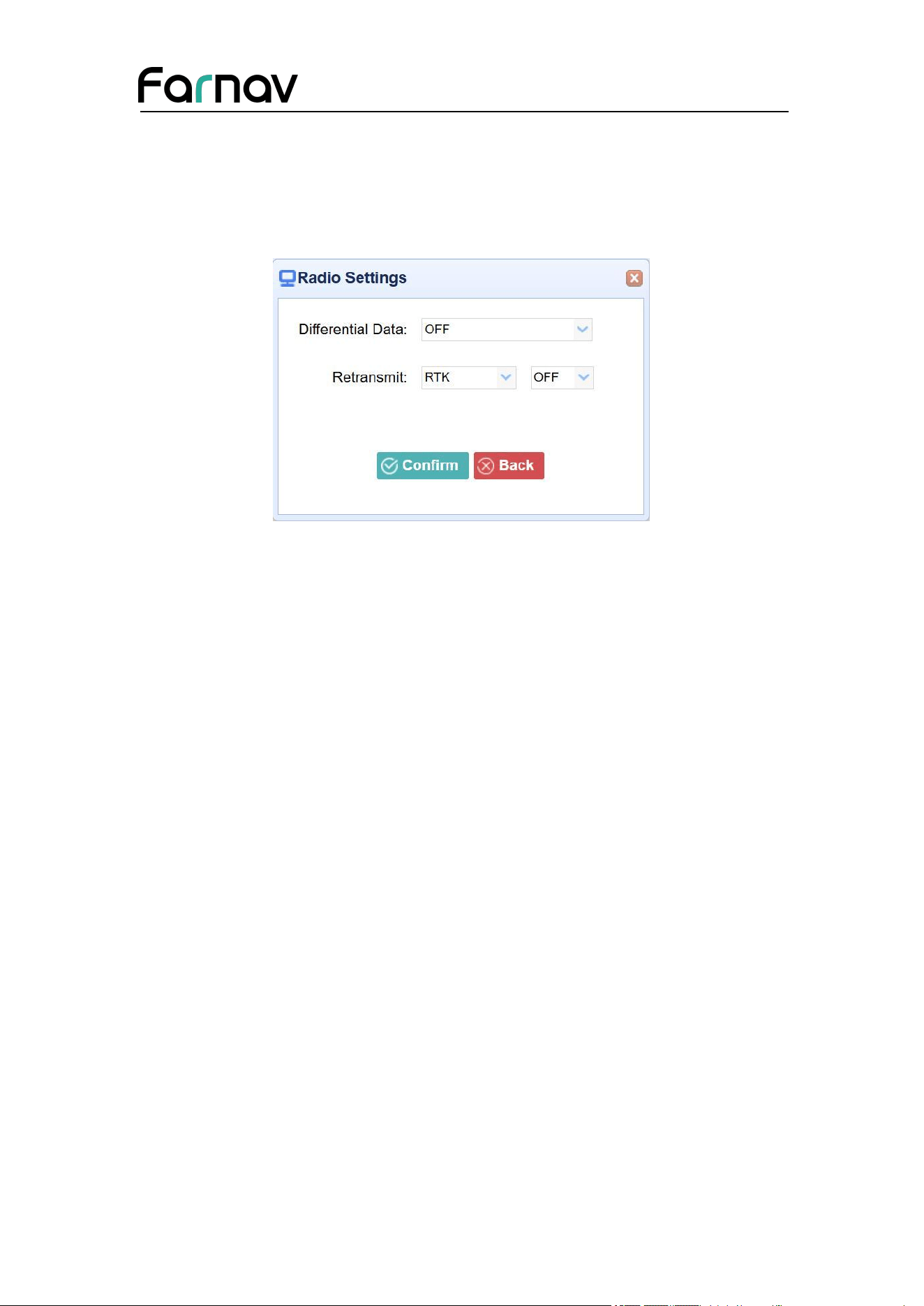
6. Radio
Tap the Settings button to the right of Radio → the Radio Settings screen will appear
→ select the format of differential data that you want to transmit through radio from the
dropdown list
➢
click to save the settings and start to transmit.
5.6 Network Setting Menu
Use this menu to view network information, configure the receiver’s mobile network,
set email alert for specific situation, configure HTTP or HTTPS port, and the
username and password of internal FTP site:
Farnav Nbase GNSS USER GUIDE
| 2026-02 P a g e | 50
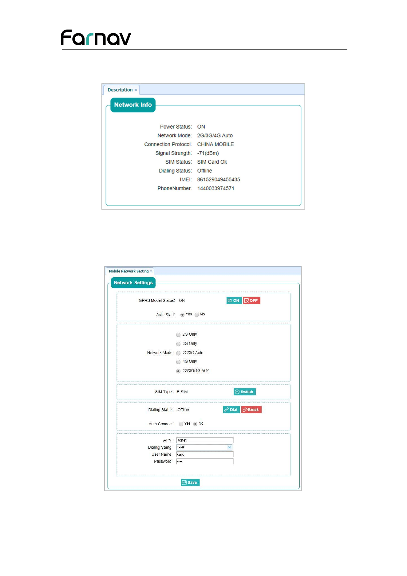
5.6.1 Description Submenu
Use this submenu to check the information of network setting.
5.6.2 Mobile Network Setting Submenu
Use this submenu to configure GPRS model, network module and modify dialing
status.
Farnav Nbase GNSS USER GUIDE
| 2026-02 P a g e | 51
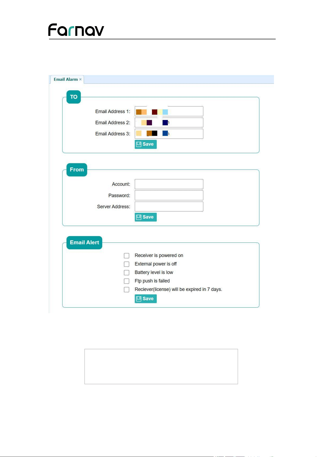
5.6.3 Email Alarm Submenu
Use this submenu to choose which situation of receiver will be alerted and input the
email address.
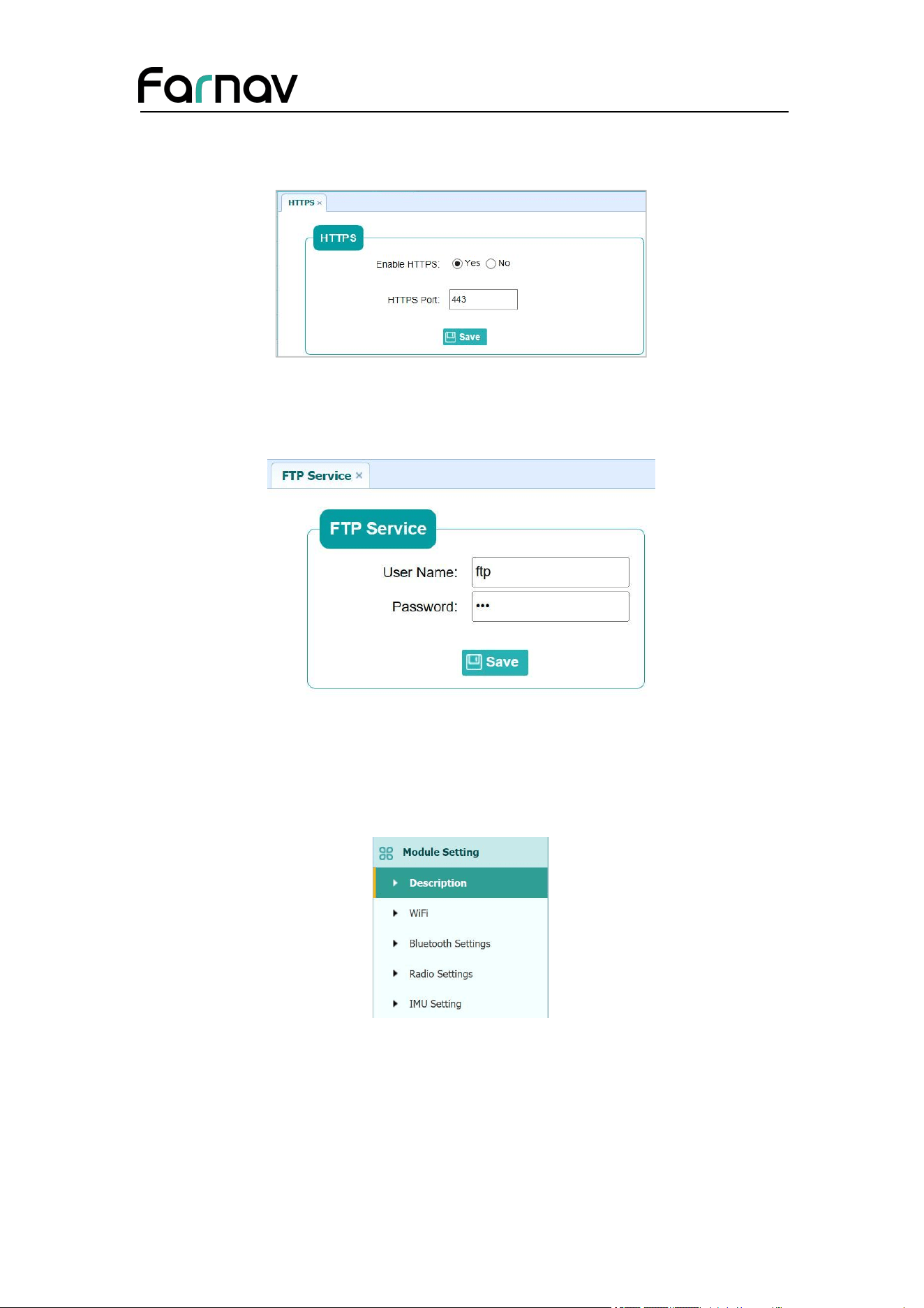
5.6.4 HTTP Submenu
Use this submenu to configure HTTP port.
Farnav Nbase GNSS USER GUIDE
| 2026-02 P a g e | 52
5.6.5 HTTPS Submenu
Use this submenu to configure HTTPS port.
5.6.6 FTP Service Submenu
Use this submenu to configure the user name and password of internal FTP site.
5.7 Module Setting Menu
Use this menu to check module information, configure WiFi, bluetooth, radio related
settings.
Farnav Nbase GNSS USER GUIDE
| 2026-02 P a g e | 53
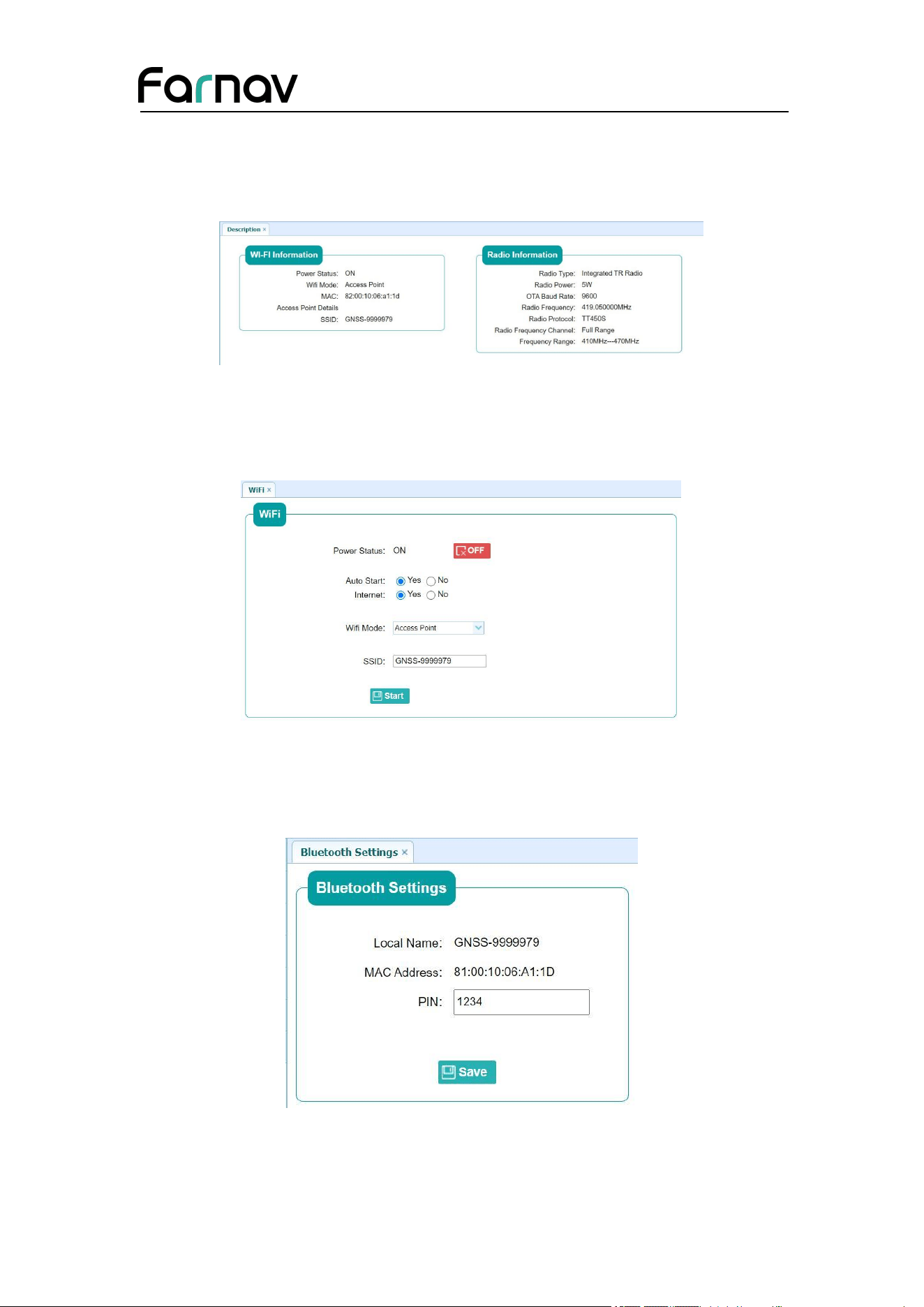
5.7.1 Description Submenu
Use this submenu to check the information of WiFi module, bluetooth module and
radio module.
5.7.2 WiFi Submenu
Use this submenu to turn on/off WiFi function and modify password.
5.7.3 Bluetooth Settings Submenu
Use this submenu to turn on/off bluetooth function and modify PIN number.
Farnav Nbase GNSS USER GUIDE
| 2026-02 P a g e | 54
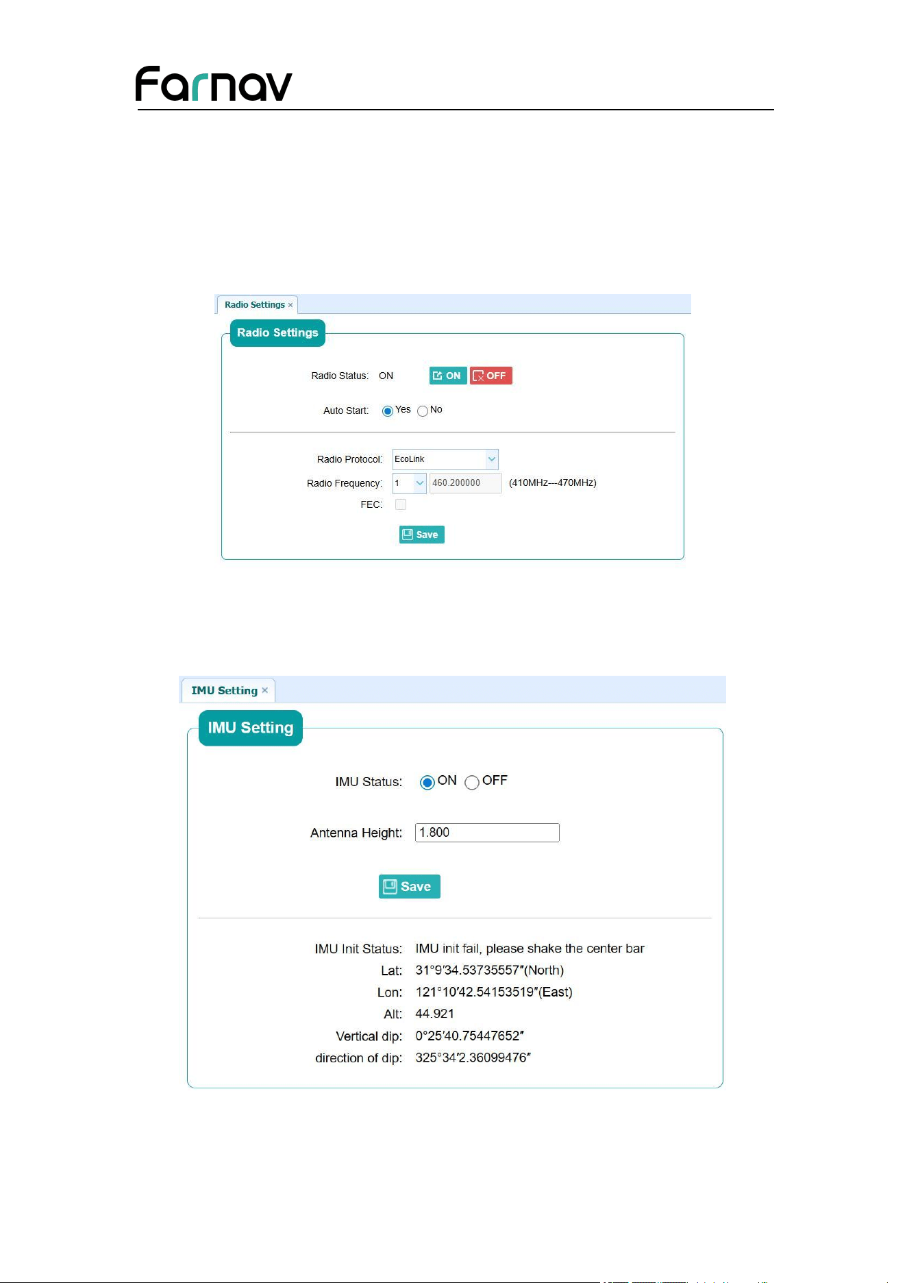
5.7.4 Radio Settings Submenu
Use this submenu to turn on/off radio function and configure radio parameters.
Note:
Instruments of different batches support different radio station protocols.
PN: A10522980909070005 supports EFIX\ Transparent\ TT450\ Satel\ EcoLink.
5.7.5 IMU Settings Submenu
Use this submenu to turn on/off IMU function.
5.8 Firmware Menu
Farnav Nbase GNSS USER GUIDE
| 2026-02 P a g e | 55
Use this menu to check the current firmware information, download the system log,
update the receiver firmware, download, or update the configuration file and register
the receiver, and more:
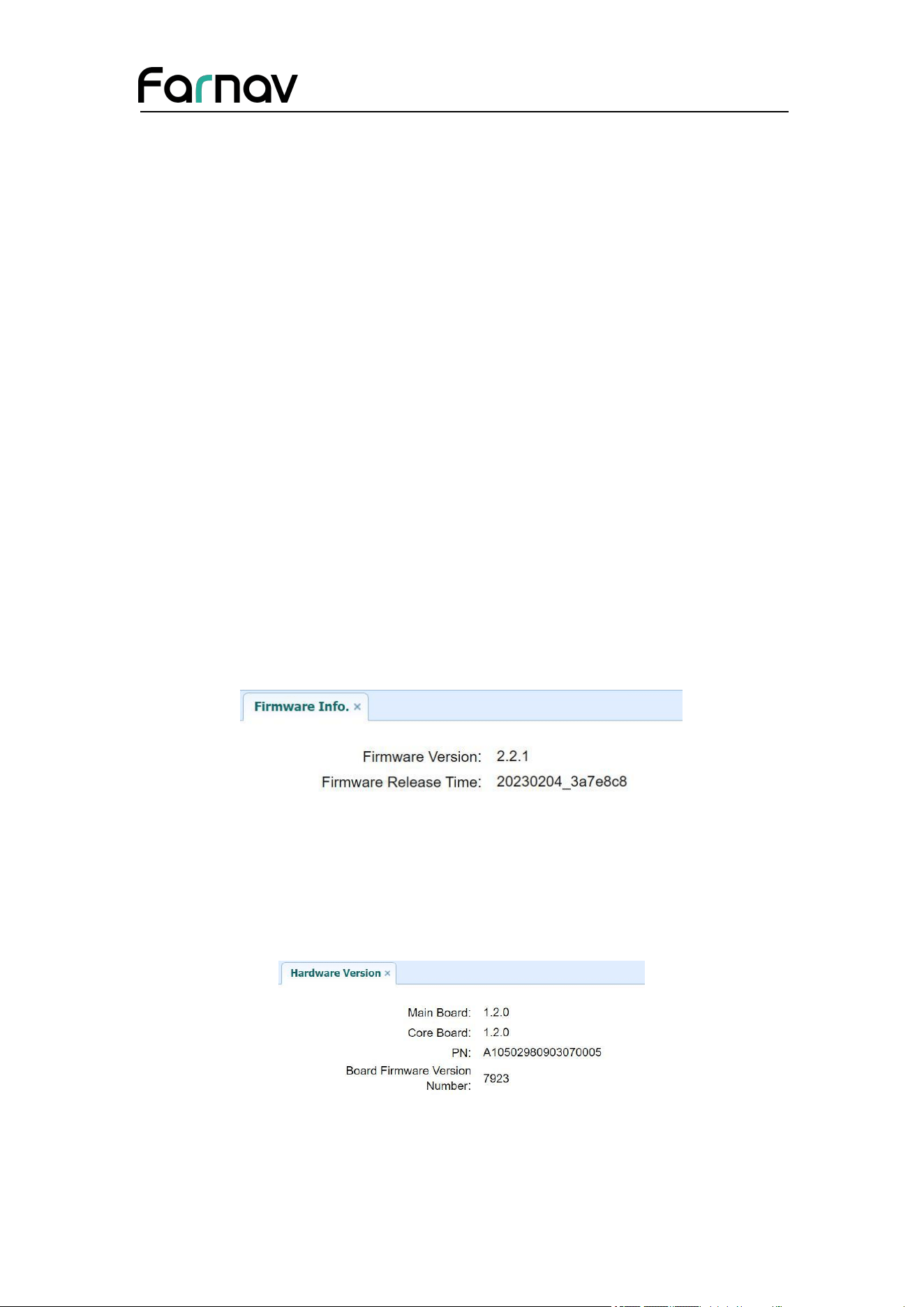
5.8.1 Firmware Info Submenu
Use this submenu to check the current firmware information. The following figure
shows an example of the firmware information.
5.8.2 Hardware Version Submenu
Use this submenu to check the hardware information, including main board version
and core board version:
5.8.3 Config File Submenu
Farnav Nbase GNSS USER GUIDE
| 2026-02 P a g e | 56
Use this submenu to update Configuration File.
5.8.4 System Log Download Submenu
Use this submenu to download the system log of the receiver.
5.8.5 User Log Submenu
Use this submenu to download the user log. Tap Download to download current user
log; Tick items that you want to see on the user log and tap confirm button to confirm
selected user log.
5.8.6 Firmware Update Submenu
Farnav Nbase GNSS USER GUIDE
| 2026-02 P a g e | 57
Use this submenu to load new firmware to the receiver across the network. Tap the
Browse button to locate the upgrade file → tap Confirm button to confirm the
selected upgrading file and start upgrading.
Notes
It may take about 3 or 4 minutes to complete the firmware upgrading. Do not
touch the power button or unplug the power until the upgrading process finishes,
or damage will be caused to the receiver.
The receiver will restart after the firmware upgrading is done, so users need to
reconnect the receiver with your computer via Wi-Fi, and then log-in the receiver
through a web browser to continue the configuration.
5.8.7 GNSS Board Upgrade Submenu
Use this submenu to upgrade GNSS Board. Use this submenu to load new board to
the receiver across the network. Tap the Browse button to locate the upgrade file →
tap Confirm button to confirm the selected upgrading file and start upgrading.
Farnav Nbase GNSS USER GUIDE
| 2026-02 P a g e | 58
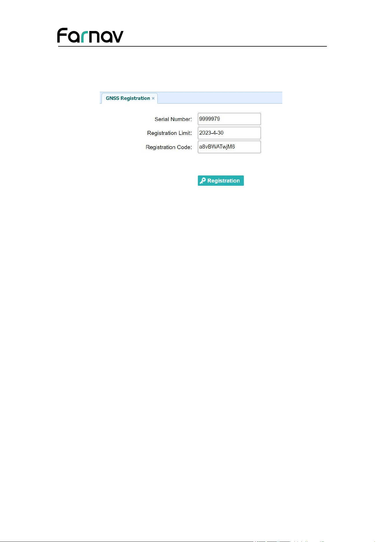
5.8.8 GNSS Registration Submenu
Use this submenu to register the receiver. Paste or enter the registration code to the
Registration Code field → tap Registration button to complete the registration.