
R100 Receiver Installation and Operation User Manual V1
R100 GNSS RECEIVER
Installation and Operation
User Manual
Shanghai AllyNav Technology Co., Ltd

R100 Receiver Installation and Operation User Manual V1
R100 GNSS RECEIVER INSTALLATION AND OPERATION USER MANUAL
Revised version:V1
Revision Date: Friday, January 9, 2026
Firmware version:V4.1.2
Warranty Information
Limited warranty period:
Products and software: 12 months from the date of shipment (receiver)
Accessories: Cable and other accessories are included for 90 days from the date of shipment.
AllyNav warrants that its GNSS products are free from defects in materials and workmanship.
During the applicable warranty period (“Warranty Period”), AllyNav will, at its sole discretion,
repair or replace at its own facility any product, accessory, or software that does not conform to
AllyNav specifications or has significant material or workmanship defects (“Defective Product”). If
the software is determined to be defective during the Warranty Period, AllyNav will, at its sole
discretion and at its own expense, provide the purchaser with a qualified software patch to resolve
the issue, or a fix included in the next general version of the affected software. This limited
warranty does not cover the costs of any software re-verification, certification, or implementation.
Qualified software patches will be provided “as is” and subject to the accompanying special
software license terms.
This limited warranty does not cover products, accessories, or software that are: (a) subjected to
abuse, misuse, negligence, fault, accident, damage during transport, improper testing, improper
installation, improper storage, improper handling, improper maintenance, abnormal physical
stress, abnormal environmental conditions, abnormal use, any other situation exceeding AllyNav
specifications, or failure to follow AllyNav instructions; (b) modified, rebuilt, repaired, or altered
by persons other than AllyNav or unauthorized by AllyNav; (c) used with any third-party products,
hardware, or equipment not approved in writing by AllyNav in advance; or (d) returned with the
original identification markings removed or altered. Furthermore, any products, accessories, or
software designated by AllyNav as test samples, experimental products, development products,
research products, prototypes, pre-production products, samples, incomplete products, or
non-conforming products, accessories, or software are provided "as is" and are expressly
excluded from this limited warranty. This limited warranty does not cover products, accessories,
and software manufactured or created by third parties ("Third-Party Materials"). AllyNav will
transfer any warranty coverage of third-party materials to the purchaser to the extent permitted
by law; however, AllyNav does not provide a separate warranty for any such third-party materials,
and the warranty period for third parties may differ from this warranty. Under no circumstances
does AllyNav guarantee that any software will operate uninterruptedly or without errors.
Except to the extent permitted by law, this Limited Warranty supersedes all other warranties,
whether arising out of law, trade custom, performance, or industry practice, and whether express
or implied, including, but not limited to, implied warranties of merchantability and fitness for a

R100 Receiver Installation and Operation User Manual V1
particular purpose; and this Warranty provides AllyNav with its sole obligation to cover any
breach of warranty and the Purchaser's sole and exclusive remedy. In no event shall AllyNav be
liable for any special, indirect, incidental, or consequential damages of any kind or nature. Any
attempt to modify or amend this Limited Warranty without the written consent of AllyNav's senior
management shall be invalid.
Document Declaration
The information contained in this document is subject to change without notice.

R100 Receiver Installation and Operation User Manual V1
Table of contents
1. Chapter 1 R100 Overview of.......................................................................................................................................9
1.1. Characteristics.................................................................................................................................................9
1.2. R100 Connector Overview..........................................................................................................................9
1.3. R100 Indicator Light (LED)........................................................................................................................10
2. Chapter 2 R100 Installation.......................................................................................................................................11
2.1. Additional accessories required for the R100 receiver................................................................... 11
2.2. Installation and Orientation of R100.....................................................................................................11
2.2.1. Installation......................................................................................................................................................11
2.2.2. Orientation.................................................................................................................................................... 12
2.2.3. R100 mounting hole location..................................................................................................................12
2.2.4. Mounting Plate.............................................................................................................................................13
2.3. Connect R100 to the data communication equipment..................................................................14
2.3.1. Serial Port.......................................................................................................................................................14
2.3.2. CAN Bus Port................................................................................................................................................14
2.3.3. Speed
Pulse Output Port.................................................................................................................14
2.4. R100 Power Requirements.......................................................................................................................14
2.5. Check if R100 is working properly.........................................................................................................14
3. Chapter 3 R100 Instruction Operation..................................................................................................................15
3.1. Communicating with the receiver..........................................................................................................15
3.1.1. Serial Port Communication...................................................................................................................... 15
3.1.2. CAN Bus Communication.........................................................................................................................16
3.2. Quick Start Guide........................................................................................................................................ 16
3.2.1. Entering Configuration Mode................................................................................................................. 16
3.2.2. Query & Save................................................................................................................................................16
3.2.3. Reset................................................................................................................................................................17
3.2.4. Working Mode............................................................................................................................................. 17
3.2.5. Straight-through module configuration..............................................................................................18
3.2.6. Internal serial port baud rate...................................................................................................................18
3.2.7. CAN Baud Rate Setting............................................................................................................................. 19
3.3. Enable SBAS positioning...........................................................................................................................19

R100 Receiver Installation and Operation User Manual V1
3.4. ALLYLINK Service.........................................................................................................................................20
3.4.1. Required Components...............................................................................................................................22
3.4.2. Enable L-BAND signal tracking.............................................................................................................. 23
3.4.3. ALLYLINK Service Subscription Method.............................................................................................. 24
3.5. R100 speed pulse signal............................................................................................................................24
3.5.1. Velocity Pulse Signal Configuration...................................................................................................... 24
4. Chapter 4 IMU Combinatorial Navigation........................................................................................................... 26
4.1. IMU Axial Description.................................................................................................................................26
4.1.1. Axial Acceleration........................................................................................................................................26
4.1.2. Axial angular velocity................................................................................................................................. 26
4.1.3. Heading Angle............................................................................................................................................. 27
4.1.3.1. Absolute heading........................................................................................................................................27
4.1.3.2. The Z-axis is parallel to the horizontal plane.....................................................................................27
4.1.4. Pitch Angle.................................................................................................................................................... 28
4.1.5. Roll Angle.......................................................................................................................................................28
4.2. Vehicle Navigation Axis Description..................................................................................................... 29
4.2.1. Heading Angle............................................................................................................................................. 29
4.2.2. Pitch Angle.................................................................................................................................................... 30
4.2.3. Roll Angle.......................................................................................................................................................31
4.3. Software Configuration............................................................................................................................. 31
4.4. Prerequisites..................................................................................................................................................31
4.4.1. Initialization Completion Requirements...............................................................................................31
5. Chapter 5 GNSS Module............................................................................................................................................32
5.1. Factory default configuration..................................................................................................................32
5.2. PPP Configuration.......................................................................................................................................32
5.3. 5.3. LBAND Configuration........................................................................................................................ 33
6. Chapter 6 Radio Module............................................................................................................................................34
6.1. Factory default configuration..................................................................................................................35
6.2. Configuration Commands........................................................................................................................36
7. Chapter 7 CAN Bus......................................................................................................................................................37
7.1. Default Configuration................................................................................................................................ 37
7.2. Configure CAN bus baud rate................................................................................................................ 37

R100 Receiver Installation and Operation User Manual V1
7.3. AllyNav Messages on CAN.......................................................................................................................38
7.3.1. CAN ID............................................................................................................................................................38
7.3.2. Angular Velocity Analysis..........................................................................................................................38
7.3.3. Acceleration Analysis..................................................................................................................................39
7.3.4. Angular Rate Analysis................................................................................................................................ 40
8. Chapter 8 Fault Diagnosis..........................................................................................................................................41
8.1. Functional Classification............................................................................................................................41
8.1.1. Module Classification Description..........................................................................................................42
8.1.2. Description of physical quantities..........................................................................................................42
8.1.3. Diagnostic Status Description................................................................................................................. 43
8.2. Print diagnostic text information............................................................................................................43
8.3. Configure diagnostic information time intervals by second.........................................................44
8.4. Configure diagnostic information time intervals in milliseconds................................................ 44
8.5. Configure diagnostic information time intervals by frequency....................................................45
8.6. Real-time access to diagnostic information.......................................................................................45
8.7. Report diagnostic information................................................................................................................46
8.8. Diagnostic Alarms....................................................................................................................................... 47
8.9. Set alarm limit...............................................................................................................................................48
8.10. Set alarm lower limit...................................................................................................................................48
8.11. Read the upper and lower alarm limits................................................................................................48
8.12. Configure and enable diagnostic alarms.............................................................................................49
8.13. Read all CAN bus message IDs...............................................................................................................49
9. Chapter 9 Firmware..................................................................................................................................................... 50
9.1. Firmware Updates and Model Upgrades............................................................................................ 50
9.1.1. Firmware Update.........................................................................................................................................50
9.1.2. Firmware Downgrade.................................................................................................................................55
9.2. Download firmware file............................................................................................................................. 55
9.2.1. Firmware File Format..................................................................................................................................55
9.3. Use QFlash to update or upgrade.........................................................................................................55
Appendix A R100 Technical Specifications.........................................................................................................56
A.1 R100 Performance Specifications...........................................................................................................56
A.2 R100 Mechanical Specifications..............................................................................................................59

R100 Receiver Installation and Operation User Manual V1
A.3 R100 Environmental and Electrical Specifications............................................................................ 59
A.4 R100 Data Communication Specification............................................................................................59
A.5 R100 Speed Pulse Specification.....................................................................................................60
A.6 R100 Antenna Interface Cable (Optional Accessory).......................................................................60
A.7 R100 Custom Cable Recommendation................................................................................................61
A.8 R100 Mounting Plate Specifications......................................................................................................62

R100 Receiver Installation and Operation User Manual V1
Customer Support
ALLYNAV Knowledge Base
If you encounter technical issues, please visit the ALLYNAV support page:
ALLYNAV.com/support.This support page allows you to contact customer support, find relevant
tutorials, and ask questions.
R100 Receiver Installation and Operation User Manual V1
1. Chapter 1 R100 Overview of
The R100 is a high-performance GNSS receiver and antenna optimized to provide position, speed,
attitude, and timing information for tractor navigation/automatic steering and precision agriculture.
This series achieves centimeter-level positioning accuracy using RTK or ALLYLINK correction
technology and integrates a combined navigation algorithm. This receiver can use all current GNSS
constellations and signals. Full-band technology provides smooth, consistent navigation, ensuring
optimal coverage even in complex conditions. Its robust, sealed housing allows for secure roof
mounting, direct use of onboard power, and provides diagnostic capabilities.
1.1. Characteristics
The main features of the R100 receiver are as follows:
A complete GNSS receiver with multi-frequency, high-precision positioning capabilities.
SBAS
L-BAND
PPP
1-channel CAN
2-channel RS232 serial ports
1-channel speed pulse output port
3 LED status indicator lights
IP67 waterproof and dustproof rating
Built-in data radio module
Wide voltage supply: 9-36V
1.2. R100 Connector Overview
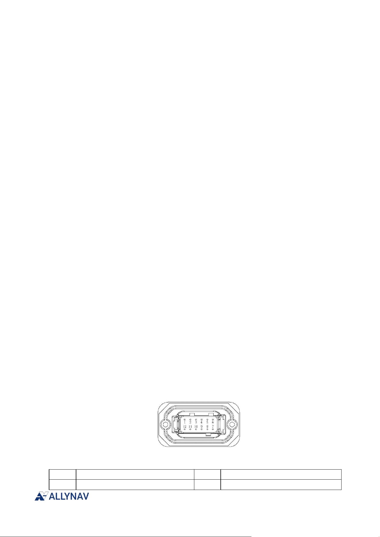
All R100 units use the same connector for power supply and communication.
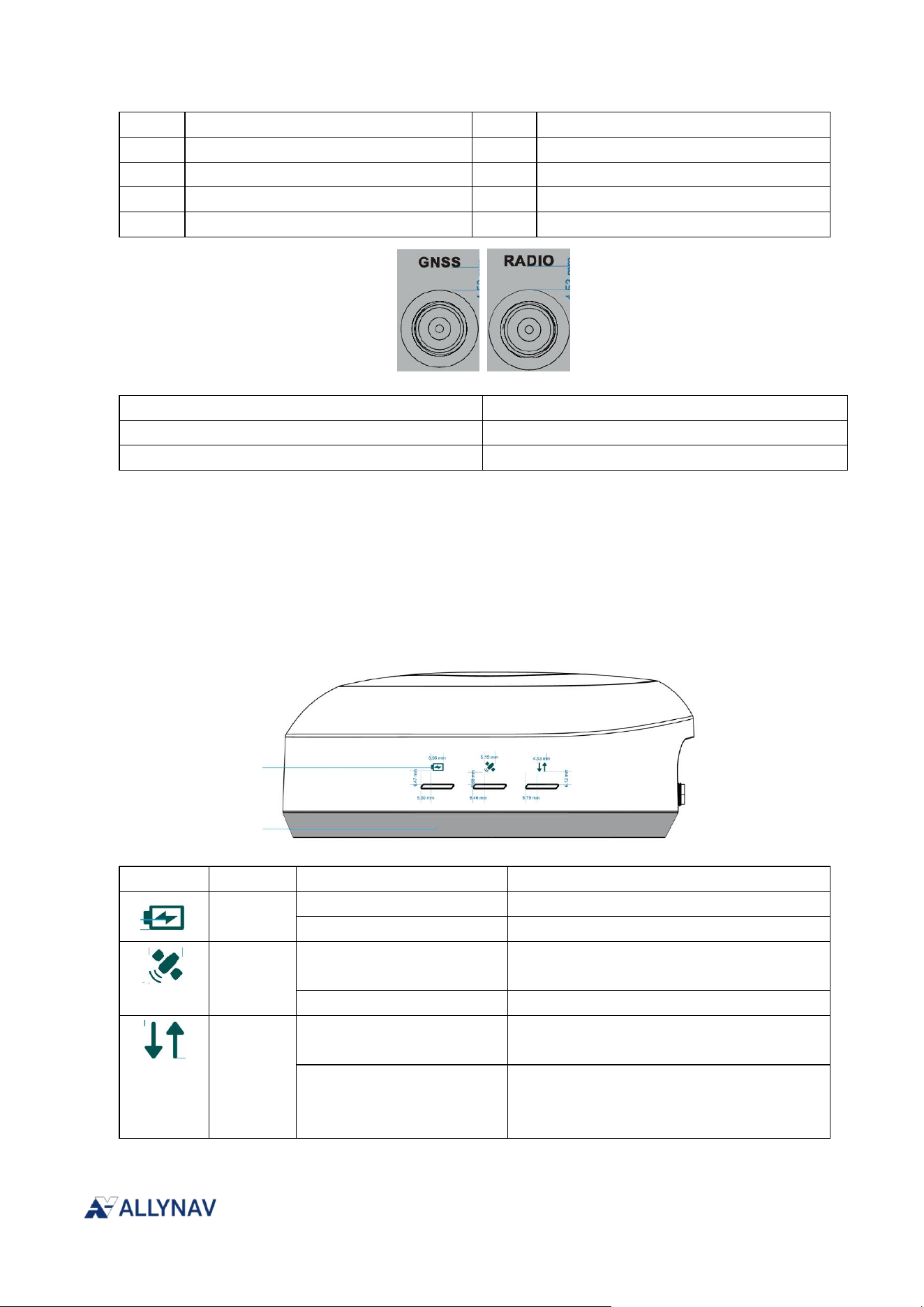
R100 interface connector
R100 Connector Pin Definitions
Pin
Function
Pin
Function
1
COM-RS232_TX
7
POW-
R100 Receiver Installation and Operation User Manual V1
2
COM-RS232_RX
8
Reserved
3
USB_D+
9
CAN_L
4
USB_D-
10
CAN_H
5
POW+
11
CONFIG-RS232_RX
6
PLS
12
CONFIG-RS232_TX
Sign
Describe
GNSS
TNC- Sub-antenna interface
RADIO
TNC - Radio Antenna Interface
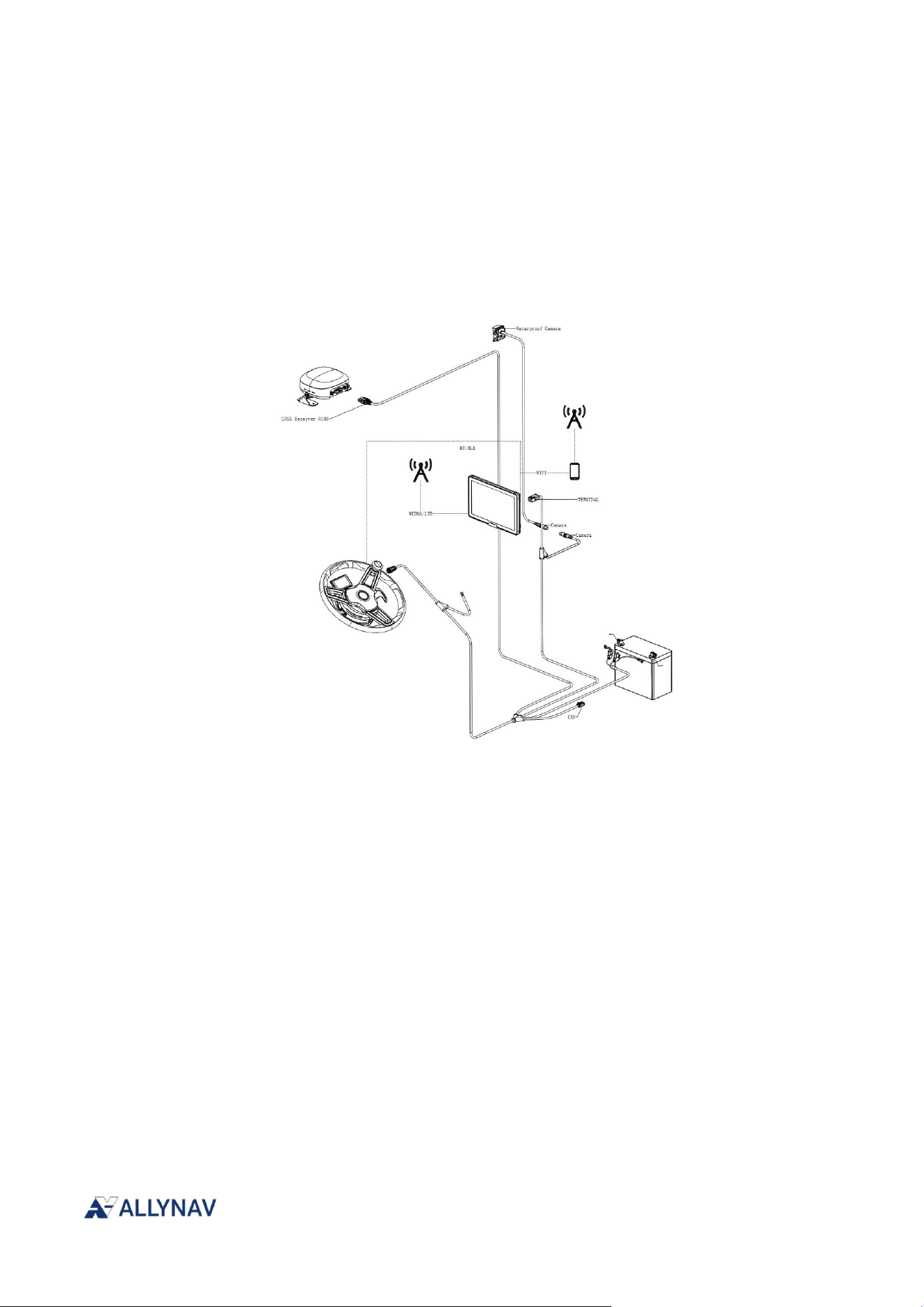
1.3. R100 Indicator Light (LED)
The R100 receiver comes standard with 3 LED indicator lights.
The following table provides information about the R100 indicator light and its status.
Sign
Definition
State
Describe
POW
Green light always on
The equipment is powered normally
Green light always off
Equipment power supply abnormality
SA
Green light always on
The positioning state reaches a fixed
solution
Green light always off
Non-fixed solution for location state
LINK
Green light flashes at 1Hz
Normal reception of differential
correction data
The green light turns on
for 500ms and then turns
off for 5 seconds.
Differential data not received correctly
R100 Receiver Installation and Operation User Manual V1
2. Chapter 2 R100 Installation
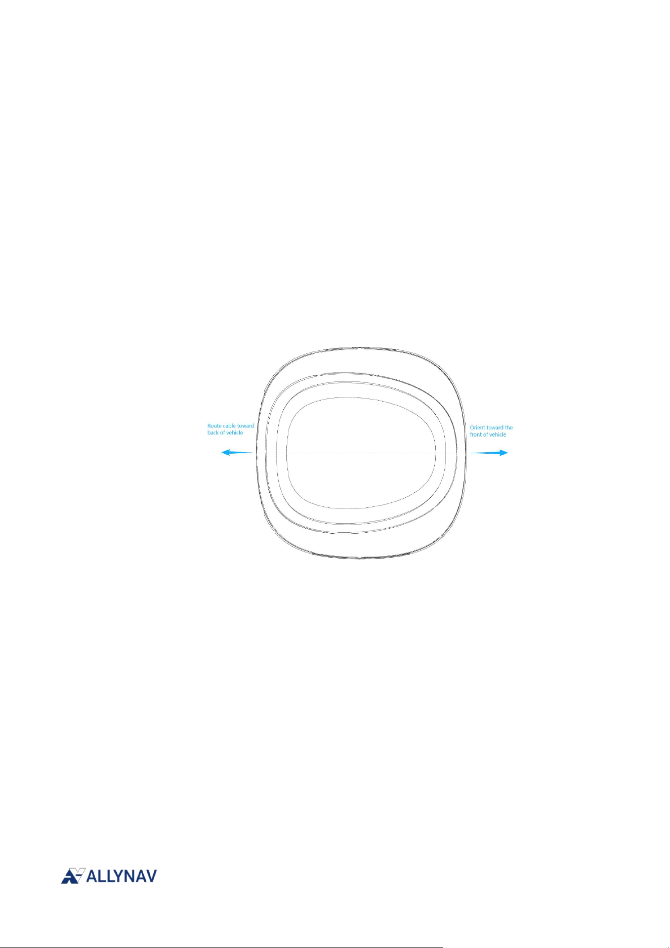
The following is a connection example for the autonomous driving kit.
2.1. Additional accessories required for the R100 receiver
1 computer (provided by the user)
1 dedicated test cable (optional)
1-channel 12V DC regulated input power supply
2.2. Installation and Orientation of R100
2.2.1. Installation
Install the R100 receiver on a safe and stable structure to ensure its safe operation in specific
environments.
R100 Receiver Installation and Operation User Manual V1
Ensure that there are no metal obstructions around the R100 receiver and that it is installed in a
location with an open view and facing the sky.
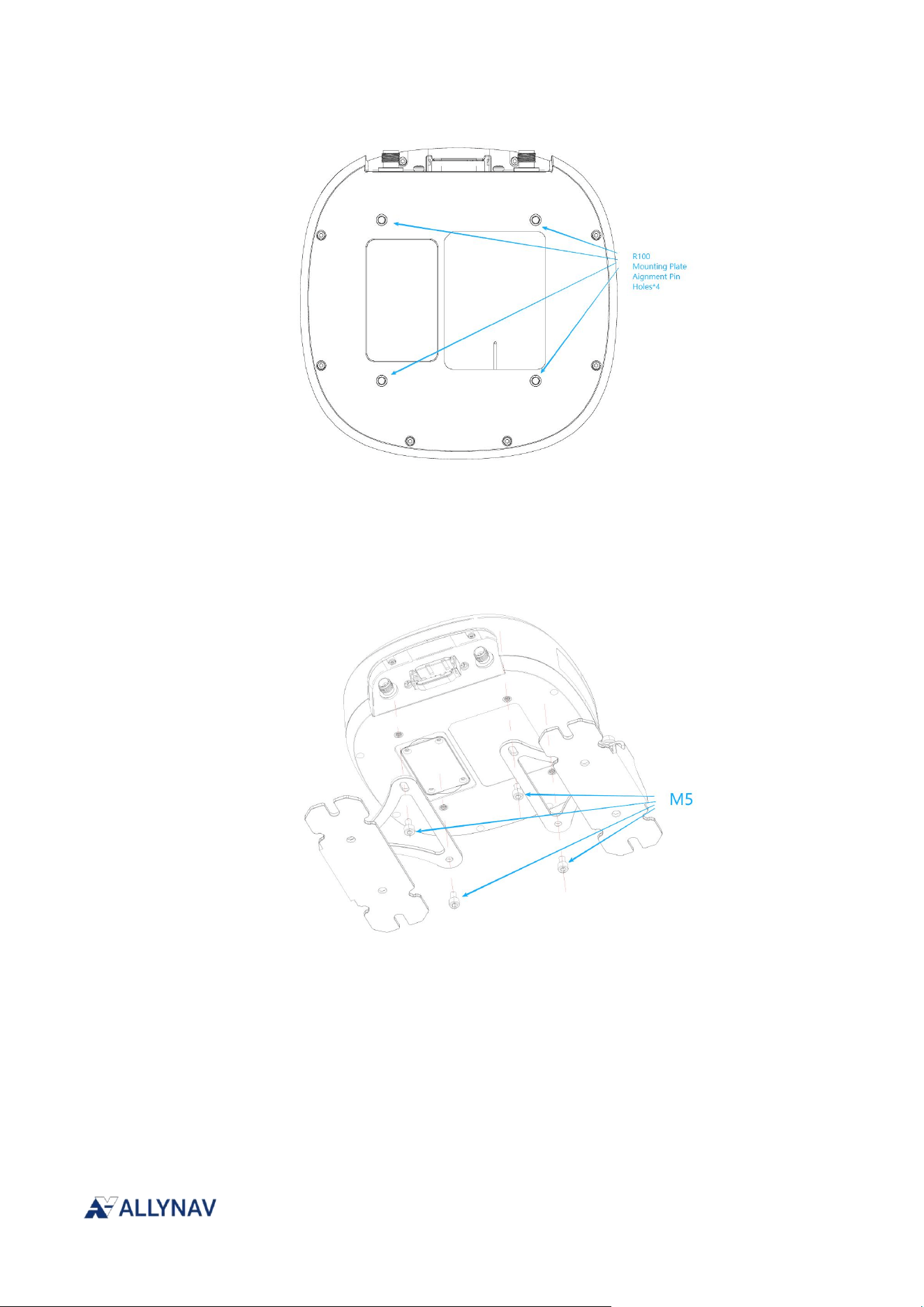
If installing on a vehicle, mount the R100 on the roof, ideally near the vehicle's pivot
point. When installing the R100, the connector must face the rear of the vehicle, and
ensure an unobstructed view of the sky from all directions.
The R100 can be mounted on the vehicle using an accessory bracket and secured with 3M
adhesive and screws.
2.2.2. Orientation
Ensure that the R100 connector faces the rear of the vehicle, with the top pointing upwards, and
that it has an unobstructed view of the sky from all directions.
2.2.3. R100 mounting hole location
The mounting hole locations for R100 are shown in the following diagram.
R100 Receiver Installation and Operation User Manual V1
2.2.4. Mounting Plate
An optional R100 mounting plate is provided to facilitate the installation of the R100. The
dimensions of the mounting plate and the location of the mounting holes are as follow.
Installation steps for the installation version:
1. Align the bracket holes with the holes on the bottom of the R100 and tighten the M5
screws.
2. Pre-installed adjustment installation position
3. Remove the 3M adhesive and screw in the fixing screws.

R100 Receiver Installation and Operation User Manual V1
2.3. Connect R100 to the data communication equipment
The R100 can communicate with other devices in the system, such as a computer's serial port. The
R100 also features a CAN bus port for communication with other CAN-compatible devices.
2.3.1. Serial Port
The R100 has two RS-232 serial ports: CONFIG and COM (through GNSS module). These ports
are located at the 12-pin connector. Pin definitions can be found in Section 1.2.
Steps to connect the serial port:
1. Connect and power the R100 receiver using a custom cable or test cable.
2. Connect the RS232 port that needs to be debugged to the serial port of a computer or other
data communication device via a DB9 connector.
2.3.2. CAN Bus Port
The R100 has a CAN bus port on its 12-pin connector.
Steps to connect to the CAN bus port:
1. Connect and power the R100 receiver using a custom cable or test cable.
2. Connect the CAN receiver or analyzer to the CAN bus of the R100.
2.3.3. Speed
Pulse Output Port
The R100 has a speed pulse output port on its 12-pin connector.
Steps to connect the speed pulse port:
1. Connect and power the R100 receiver using a custom cable or test cable.
2. The velocity pulse port can be connected to the implement port or an oscilloscope for
observation.
2.4. R100 Power Requirements
The usable voltage range for R100 devices is 6-36V. The power supply should provide at least 5W
of power.
2.5. Check if R100 is working properly.
After the receiver antenna is installed, turn on the power supply and follow these steps to confirm
that the device is working properly:
1. Check if the power light is constantly green.

R100 Receiver Installation and Operation User Manual V1
2. Connect the device to the computer via serial port.
3. Open CRT or other serial port tools
4. Send the following command
SYS CONFIG
SET CONCOM 12
SET MODE 0
MODE
The device will return the following to indicate that it is working properly:
#MODE,98,GPS,FINE,2399,196081000,0,0,18,880;MODE ROVER,HEADINGMODE
FIXLENGTH*0A
3. Chapter 3 R100 Instruction Operation
3.1. Communicating with the receiver
3.1.1. Serial Port Communication
The receiver can communicate with a PC or terminal via the serial port. The default configuration
of the serial port is as follows:
115200bps
No parity bit
88 data bits
1 stop bit
No need to use RTS/CTS hardware handshake
Echo is off; the characters you type will not be displayed in the local terminal
Break function enabled
The device can modify the communication baud rate via commands. Due to limitations in the
operating environment, hardware, and cable performance, the maximum supported baud rate is
460800bps. Users can configure the communication baud rate appropriately based on their
actual usage. It should also be noted that the actual transmission rate may be lower than the set
value, depending on the number of currently tracked satellites and the idle time between data
transmissions. To avoid data loss, it is recommended to allow for a certain margin when
selecting the rate.
Using remote terminal communication

R100 Receiver Installation and Operation User Manual V1
One way to communicate with the receiver is through a remote terminal. When communicating
with the terminal, the receiver only needs to use three lines: CONFIG-RS232_RX (receive),
CONFIG-RS232_TX (transmit), and GND (ground). It is essential to ensure that the terminal's
communication settings match the receiver's port settings.
3.1.2. CAN Bus Communication
The R100 device has an onboard CAN port. It supports switching between 250kbps and 500kbps
baud rates.
Note: The R100 has a built-in CAN transceiver, but a proper bus termination resistor is still
required.
Modify the communication rate using the "SET CAN" command.
1.SYS CONFIG
2.SET BAUD 250 // After the command is sent, the receiver will restart and the configuration
will be automatically saved.
3.2. Quick Start Guide
3.2.1. Entering Configuration Mode
Enable configuration: All configuration items that begin with the keyword SET must first be
unlocked by sending this command.
[CONFIG-RS232] SYS CONFIG
Return:
OK
3.2.2. Query & Save
This command must be sent if the modified configuration items need to be saved after a power
outage. It also returns system configuration information.
[CONFIG-RS232] SYS SAVE
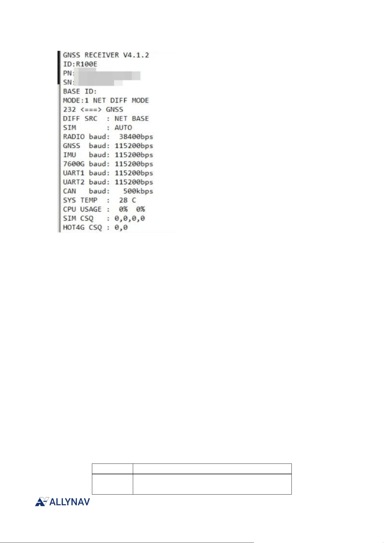
R100 Receiver Installation and Operation User Manual V1
3.2.3. Reset
The device restart command will cause the baseboard, GNSS module, IMU module, and radio
module to restart without changing the system configuration.
[CONFIG-RS232] SYS RESET
Return:
OK/FAILED
3.2.4. Working Mode
Switch the receiver's operating mode according to different usage scenarios.
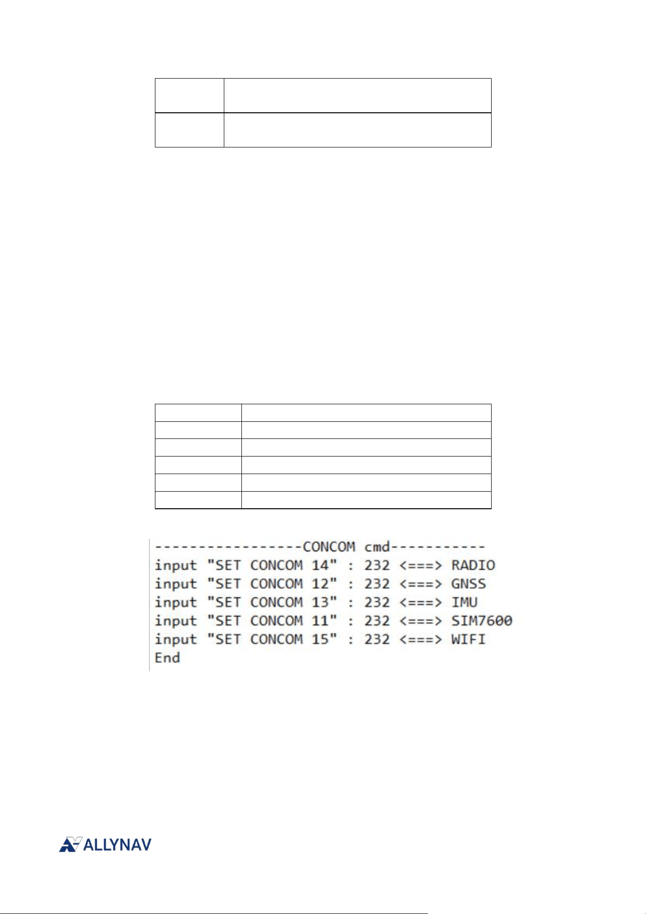
[CONFIG-RS232] SET MODE x
Return:
OK
Query:
GET MODE
X
illustrate
0
Configuration mode allows direct configuration of
each module.
R100 Receiver Installation and Operation User Manual V1
2
In serial differential mode, differential data is
received from external input via [CONFIG-RS232].
3
Radio differential mode, receiving differential data
broadcast by the base station via radio.
3.2.5. Straight-through module configuration
In MODE 0 mode, this command allows configuration switching, enabling direct serial
communication with the internal GNSS, IMU, and radio modules for configuration operations.
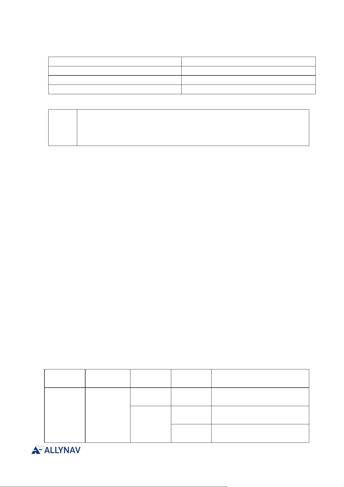
[CONFIG-RS232] SET CONCOM xx
Return:
OK/FAILED
Query:
GET CONCOM
XX
Module
11
SIM7600(Special hardware version)
12
GNSS
13
IMU
14
RADIO
15
WIFI(Special hardware version)
3.2.6. Internal serial port baud rate
This command allows you to configure the baud rate of the GNSS, IMU, and RADIO modules
and the CONFIG-RS232 serial port. Before modifying, please ensure that the module's baud rate
is already consistent with the one you want to change.
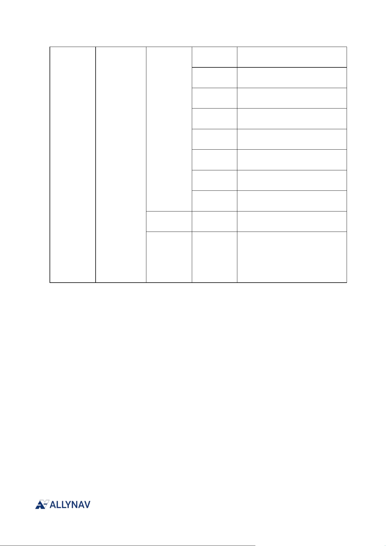
[CONFIG-RS232] SET UARTBD x,baud
Return:
R100 Receiver Installation and Operation User Manual V1
OK/FAILED
X
Module
0
RADIO
1
GNSS
2
IMU
baud
38400、9600, 19200, 38400, 57600, 115200, 230400, 460800, 921600
Note: This parameter needs to be configured according to the actual baud rate
supported by the module and usage requirements. Unless otherwise specified, the
factory default configuration is recommended.
3.2.7. CAN Baud Rate Setting
This command sets the baud rate of the CAN bus.
[CONFIG-RS232] SET CAN 250/500
After the command is sent, the receiver will automatically restart and save the configuration; the
entire process takes about 3 seconds.
3.3. Enable SBAS positioning
This command configures the SBAS function to be enabled or disabled. SBAS function
configuration supports both user-selected SBAS correction system (AUTO mode) and specified
correction system. If you are familiar with the operation of the correction system in your region, it
is recommended to specify the correction system in the configuration.
command format:
CONFIG SBAS [Parameter 1] [Parameter 2]
Command Examples:
CONFIG SBAS ENABLE WAAS
CONFIG SBAS TIMEOUT 600
Command
Header
Function
Name
Parameter 1
Parameter 2
Parameter Description
CONFIG
SBAS
ENABLE
Auto
SBAS automatically selects the
correction system mode
ENABLE
WAAS
Enable WAAS correction function
separately
GAGAN
Enable GAGAN correction
function separately
R100 Receiver Installation and Operation User Manual V1
MSAS
Enable MSAS correction function
separately
EGNOS
Enable EGNOS correction
function separately
SDCM
Enable SDCM correction function
separately
ASECNA
Enable ASECNA correction
function separately
KASS
Enable KASS correction function
separately
SPAN
Enable SPAN correction function
separately
BDS
Enable BDS SBAS correction
function separately
SLAS
Enable QZSS SLAS correction
function separately
DISABLE
-
SBAS function is disabled
(default).
TIMEOUT
t
SBAS timeout configuration,
scope:
120~1800s,The default value is
1200s; if configured to 0, it is
equivalent to DISABLE.
3.4. ALLYLINK Service
借 With the help of ALLYLINK service, the R100 receiver can achieve centimeter-level positioning
accuracy through one of three methods.
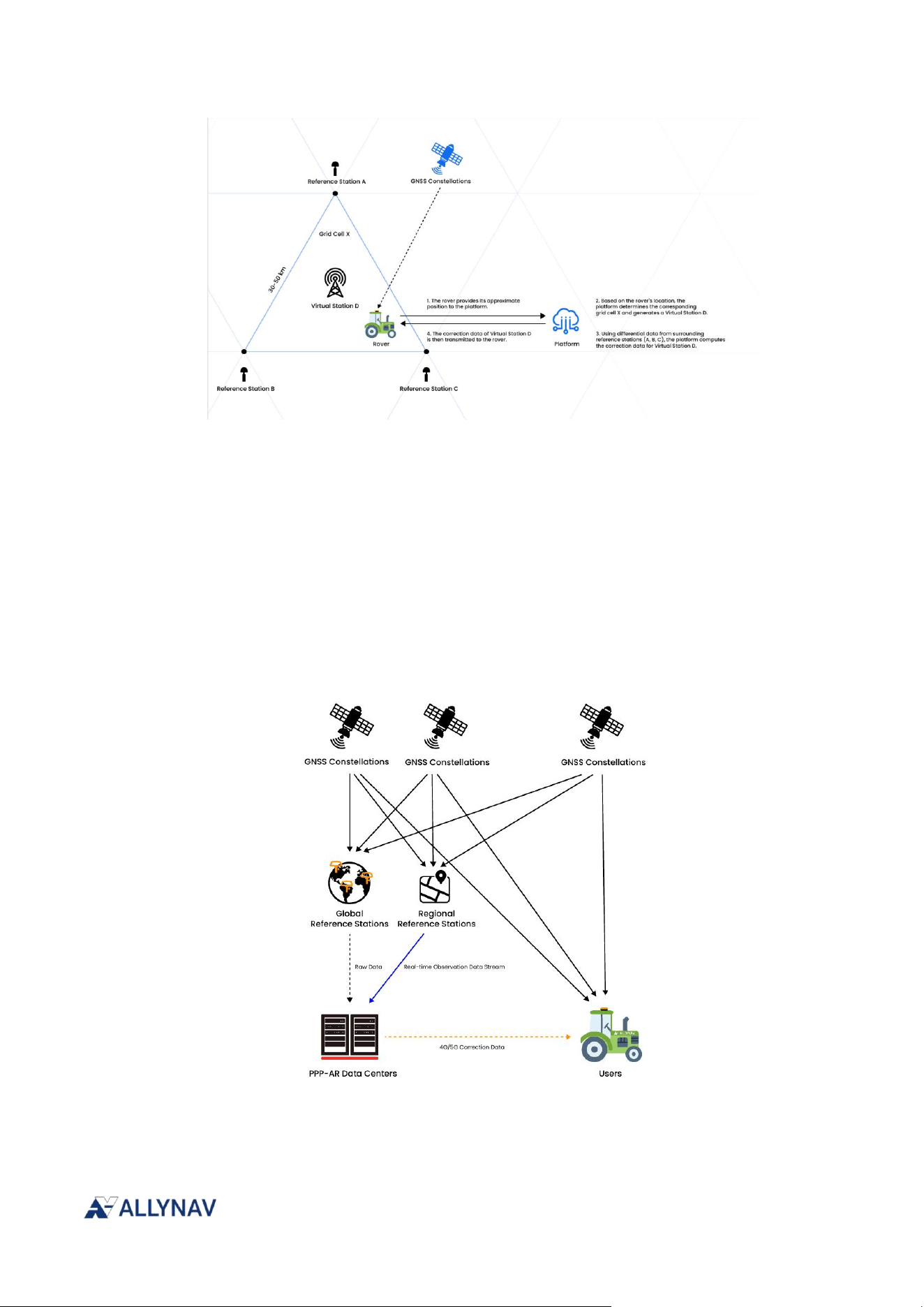
ALLYLINK-FOCUS
AllyLink-Focus delivers centimeter-level positioning with full-constellation, full-frequency GNSS
support. Backed by AllyNav’s ground-based reference station network and cloud platform, it
provides high-preci sion RTK correction data through a seamless network service, ensuring
AllyNav users benefit from a more accurate and reliable farming experience.
R100 Receiver Installation and Operation User Manual V1
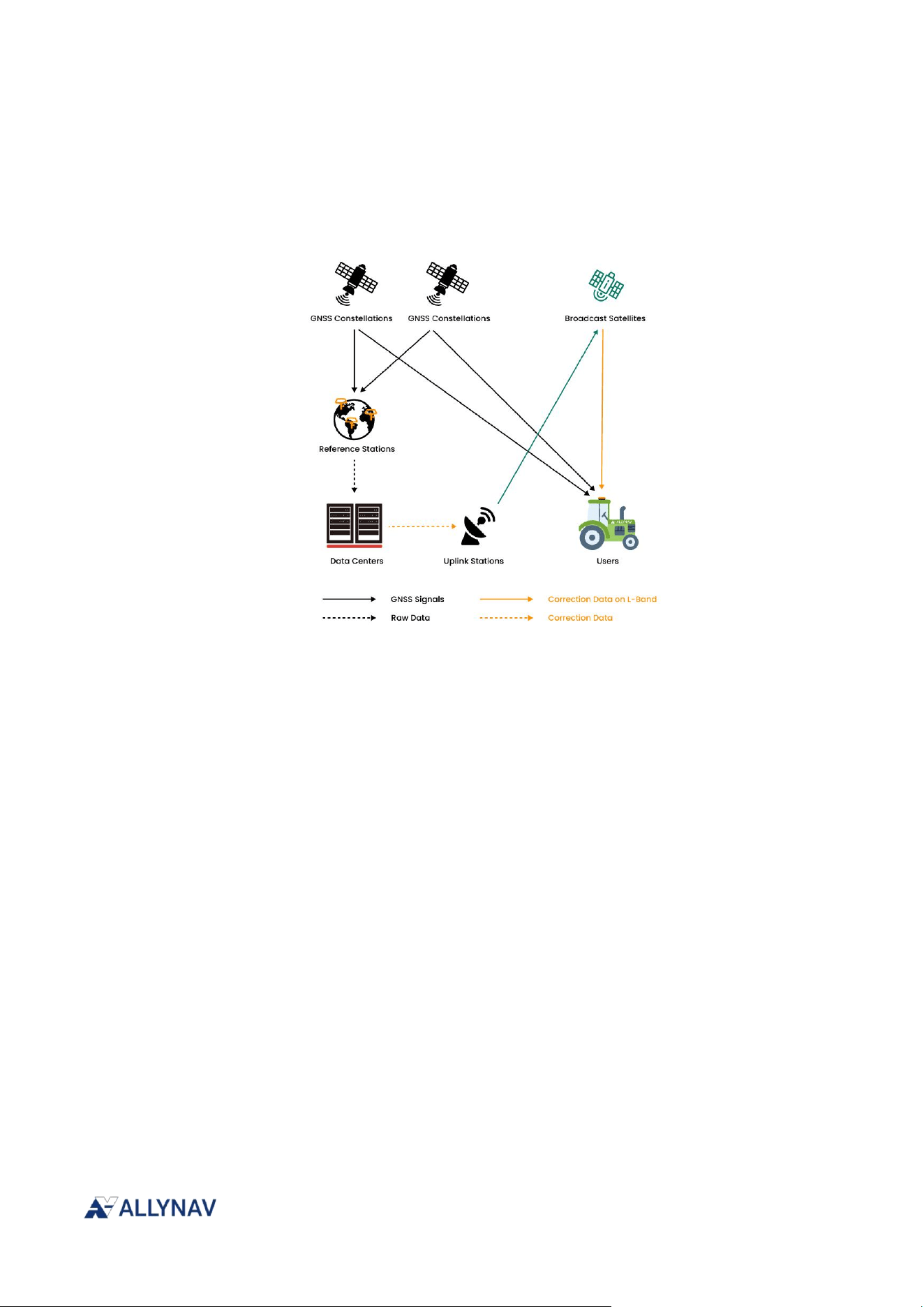
ALLYLINK-IP
AllyLink-IP provides real-time, centimeter-level global positioning via a network connection,
achieving horizontal accuracy better than 3 cm and vertical accuracy better than 6 cm
*
;
convergence typically takes under 5 minutes. With global coverage and high availability,
AllyLink-IP supports a wide range of high-pre cision applications for AllyNav customers
worldwide.
*
Convergence may take up to 20 minutes under open-sky, interference-free conditions to reach full accuracy.
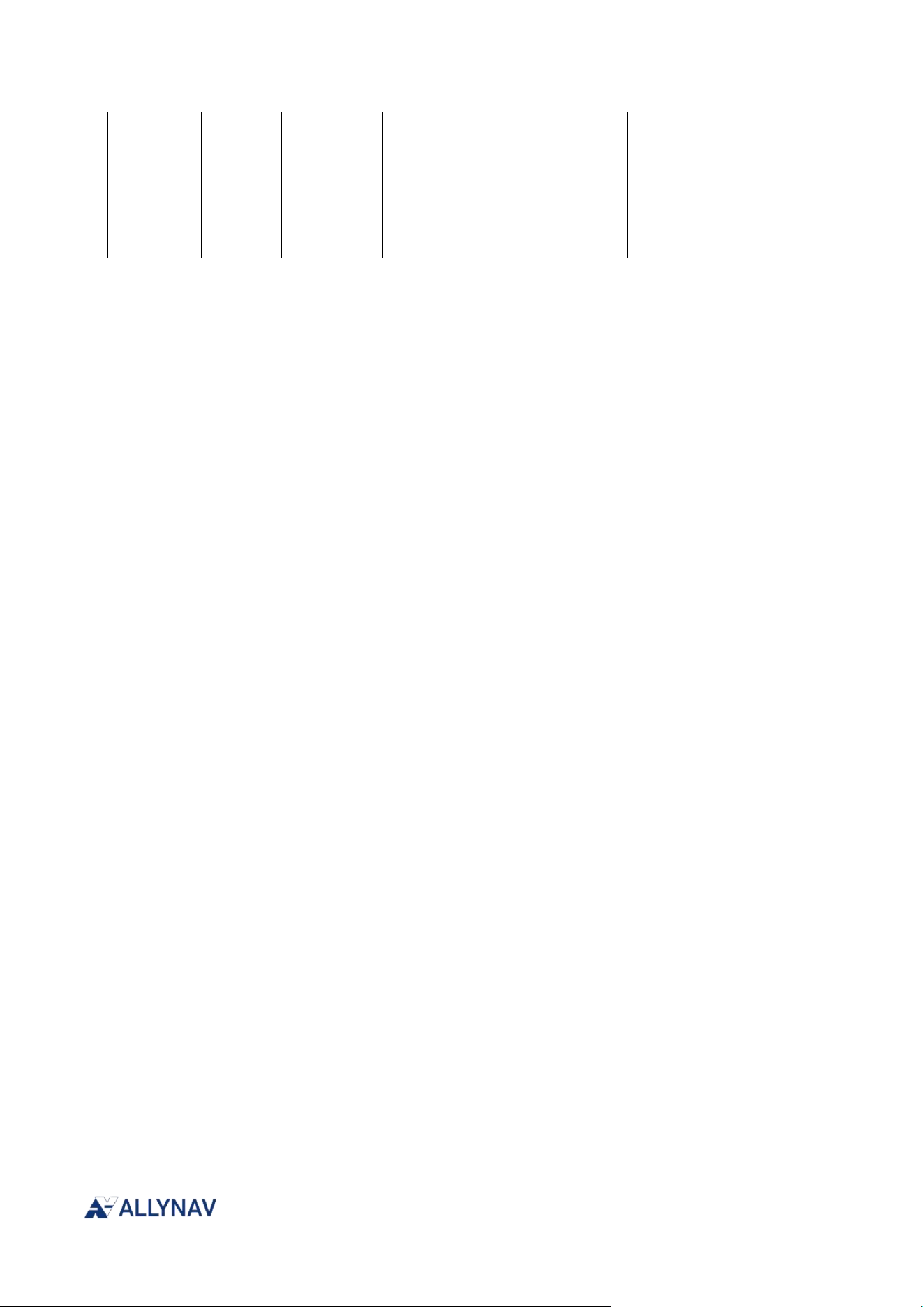
ALLYLINK-REACH
ALLYLINK-REACH, a satellite-based augmentation system developed by Linklink Technologies, is
R100 Receiver Installation and Operation User Manual V1
a satellite-based positioning service that enables users to achieve centimeter-level high-precision
positioning globally. It effectively addresses the need for high-precision positioning in areas
without network coverage. Centimeter-level high-precision positioning can be achieved
anywhere in the world without relying on a network, significantly improving operational flexibility.
To use the ALLYLINK service, please follow these steps:
1. Ensure your GNSS system has the required components. See “Required Components”
below.
2. The L-BAND function is enabled by default. Please refer to "Enabling L-BAND Signal
Tracking" below.
3. To obtain a standalone license for L-BAND or IP services, please refer to "ALLYLINK Service
Subscription Methods" below.
3.4.1. Required Components
To use ALLYLINK services, a GNSS system requires the following components.
One R100 receiver
GNSS module hardware and firmware compatible with ALLYLINK services
ALLYLINK_FOCUS- All hardware and firmware support
ALLYLINK_IP-All receiver models support this feature; however, an additional

R100 Receiver Installation and Operation User Manual V1
terminal capable of running IP services is required to input differential data to the
receiver.
ALLYLINK_REACH- LBAND signal tracking service requires GNSS module model
numbers to end with 'C' and firmware version numbers to end with 'L'.
3.4.2. Enable L-BAND signal tracking
CONFIG LBAND Commands can configure L-band satellite information
command format:
CONFIG LBAND [Parameter 1] [Parameter 2] [Parameter 3]
Command Examples:
CONFIG LBAND ENABLE AUTO
Command
Header
Function
Name
Parameter
1
Parameter 2
Parameter
3
Parameter Description
CONFIG
LBAND
DISABLE
LBAND is off; this is the
default setting.
ENABLE
AUTO
The tracking lobe bundle
and channel are
automatically switched
according to the strategy
module.
BeamID
ID
BeamID allows you to
specify an L-band
satellite, which will be
used preferentially for
PPPAR positioning. This
command will not take
effect if BeamID is not
configured.
Value range: Decimal
integer 1 to 7.
DATUM
WGS84
Reference coordinate
system: WGS84
coordinate
system(Default)
LBANDORIGINAL
The coordinate system is
consistent with that of
the service.
BEAM
Parameter set
The parameter set should
include all parameters
R100 Receiver Installation and Operation User Manual V1
shown in Table 4-23,
which describes the L
band Beam parameter
set configuration, with
one space between each
parameter.
3.4.3. ALLYLINK Service Subscription Method
ALLYLINK-FOCUS
It requires centimeter-level accuracy within the coverage area of
ALLYNAV's self-built
CORS base stations, which can be built by distributors or users themselves.
ALLYLINK-IP
By providing real-time, centimeter-level global positioning services through network
connectivity, it effectively solves the challenge of achieving high-precision positioning in areas
with sparse base station coverage.
ALLYLINK-REACH
Developed by AllyNav, satellite-based location services enable users to achieve
centimeter-level accuracy globally.
For more information about ALLYLINK services, please contact ALLYNAV technical support or visit
the ALLYNAV website.
3.5. R100 speed pulse signal
By configuring the receiver to output a speed pulse signal, this signal can be sent to external
agricultural implements.
3.5.1. Velocity Pulse Signal Configuration
The speed specified in the GPRMC statement is converted into a PWM frequency with a 50%
duty cycle according to a specific ratio.
SET PWMFREQ mode,freq
Return:
Set pwm freg auto
SET PWMRATIO x
R100 Receiver Installation and Operation User Manual V1
Return:
Set pwm speedratio x success\r\n
Parameter
value
illustrate
Mode
0
In automatic mode, the program automatically converts the RMC
speed to PWM frequency. In this mode, the value is invalid and can be
left blank.
1
Manual mode allows users to manually specify a fixed PWM output
frequency.
freq
[0, MAX]
The value of MAX depends on the requirements. When freq is 0, it can
be understood as disabling PWM functionality. The duty cycle is 0.
x
10-60
If we set the frequency to 10 for a speed of 1 km/h, the proportional
relationship is that 1 km/h corresponds to a frequency of 10 Hz.
Example 1:
Switch to automatically output PWM frequency based on RMC speed.
SYS CONFIG
SET PWMFREQ 0
SYS SAVE
Example 2:
Manually configure the PWM frequency to 500Hz
SYS CONFIG
SET PWMFREQ 1,500
SYS SAVE
Example 3:
SYS CONFIG
SET PWMRATIO 10
SYS SAVE
This indicates that the output is set to correspond to a frequency of 10Hz for a speed of
1km/h.
R100 Receiver Installation and Operation User Manual V1
4. Chapter 4 IMU Combinatorial Navigation
A data fusion algorithm combining IMU and GNSS data is run within the R100 receiver to achieve
high-precision orientation and attitude measurement with resistance to magnetic interference.
4.1. IMU Axial Description
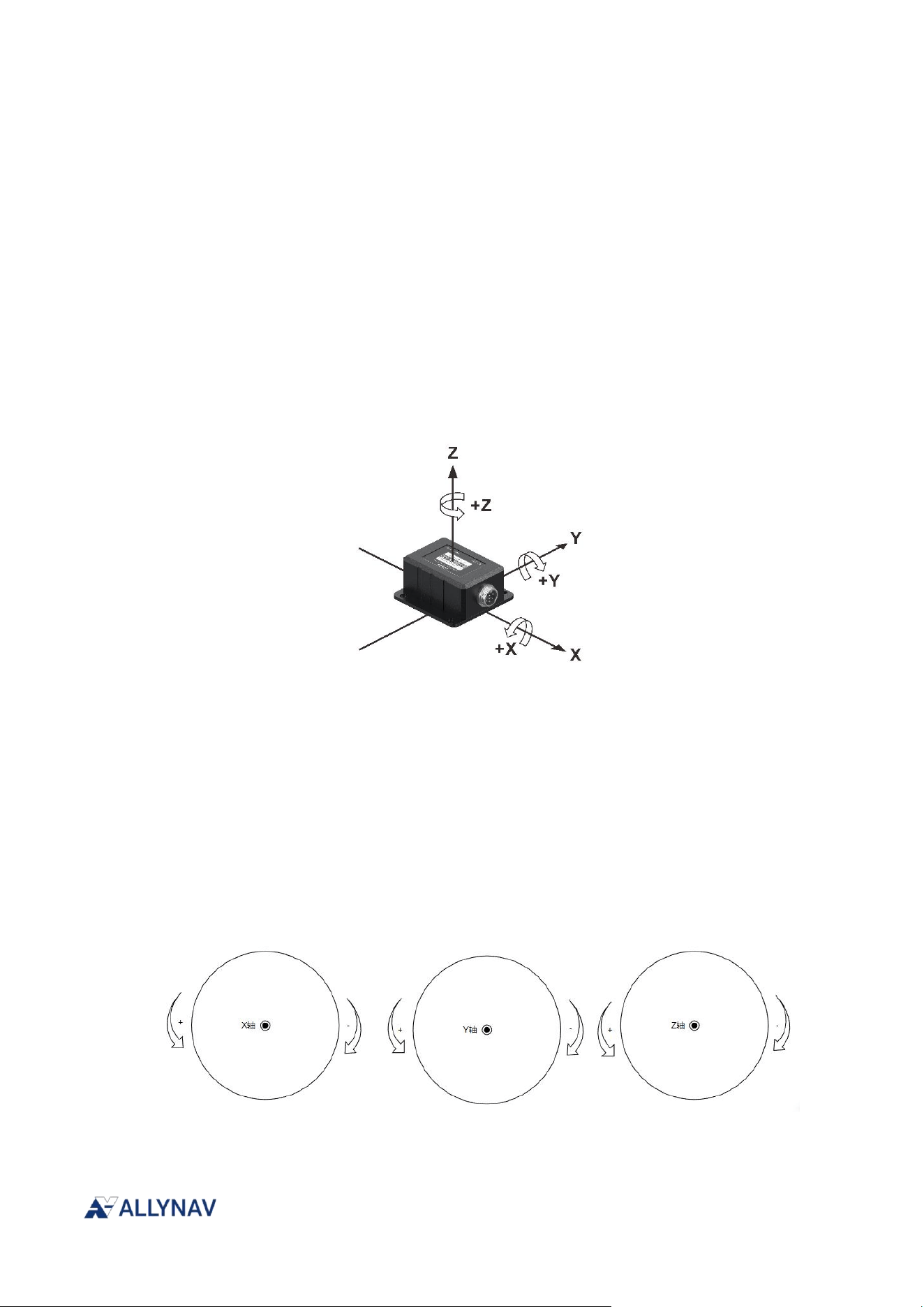
4.1.1. Axial Acceleration
The diagram below defines the axial acceleration of a gyroscope: the arrow points in the positive
direction. The acceleration range for all three axes is -8g to 8g.
4.1.2. Axial angular velocity
Angular velocity is axially aligned with acceleration, as shown in the diagram below during rotation:
all three axes are perpendicular to the document and point outwards; clockwise rotation results in
negative values, and counterclockwise rotation results in positive values. The acceleration range for
all three axes is -640°/s to 640°/s.
R100 Receiver Installation and Operation User Manual V1
4.1.3. Heading Angle
4.1.3.1. Absolute heading
In reality, the gyroscope cannot obtain the absolute heading on its own. Therefore, it can be
assumed that the heading is south during initialization. If the absolute heading is obtained during
integrated navigation, it will be output according to the following description. At this time, the data
format can directly correspond to the heading of the positioning data, and the data can be
transmitted directly in bytes.
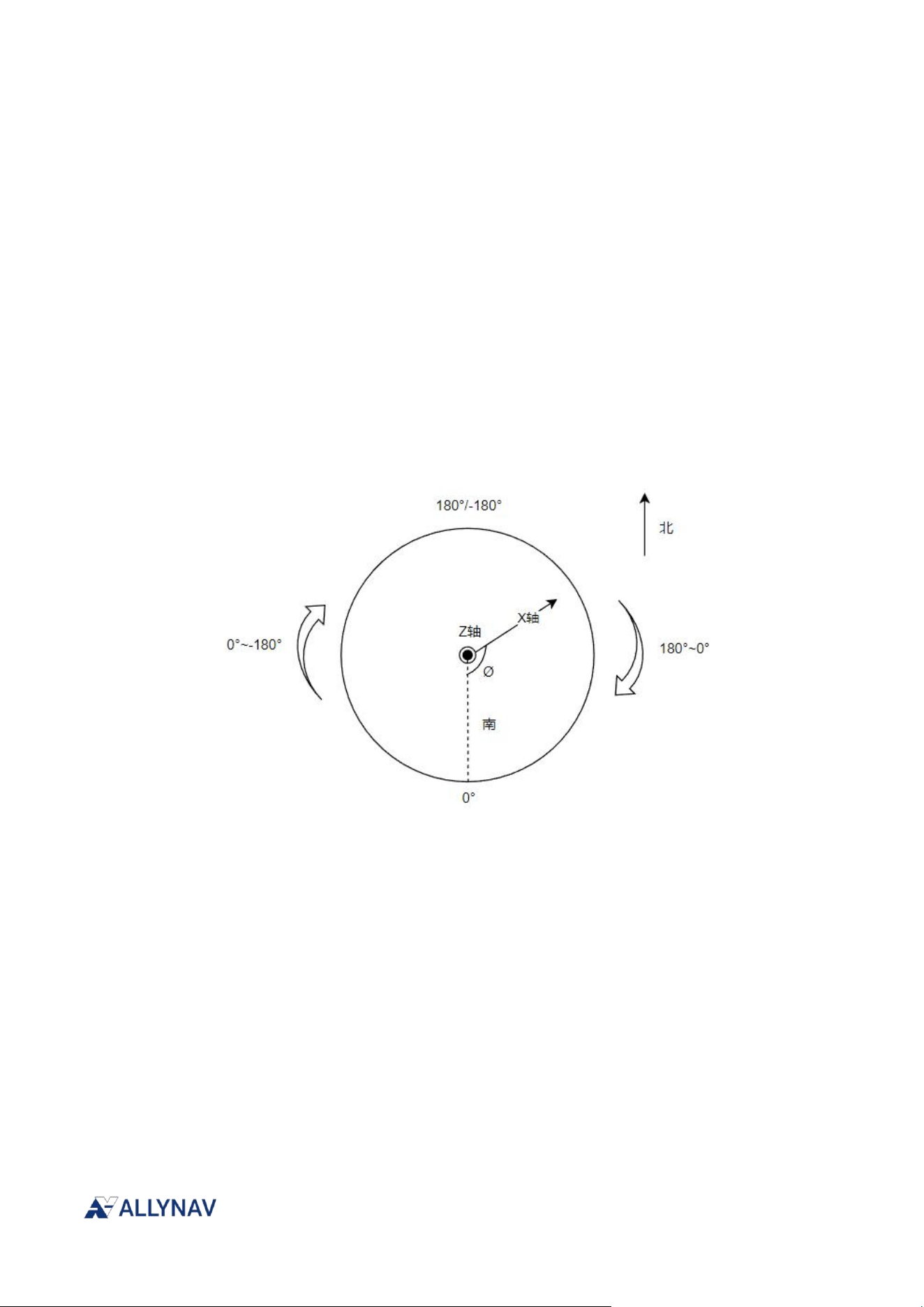
As shown in the figure: The disk surface is parallel to the horizontal plane, the dashed line is the
north-south line, the Z-axis points upwards and is perpendicular to the horizontal plane and
outwards from the document. Due to the data offset of 180°, true north corresponds to
+180°/-180°, and the heading angle is Ø, ranging from -180° to 180°.
4.1.3.2. The Z-axis is parallel to the horizontal plane.
When vertical mounting is used, the Z-axis is parallel to the horizontal plane and is affected by the
neutral force. In order to make the attitude data continuous, the output angle is actually pitch or
roll, and the data calculation method is also the same as that of two axes.
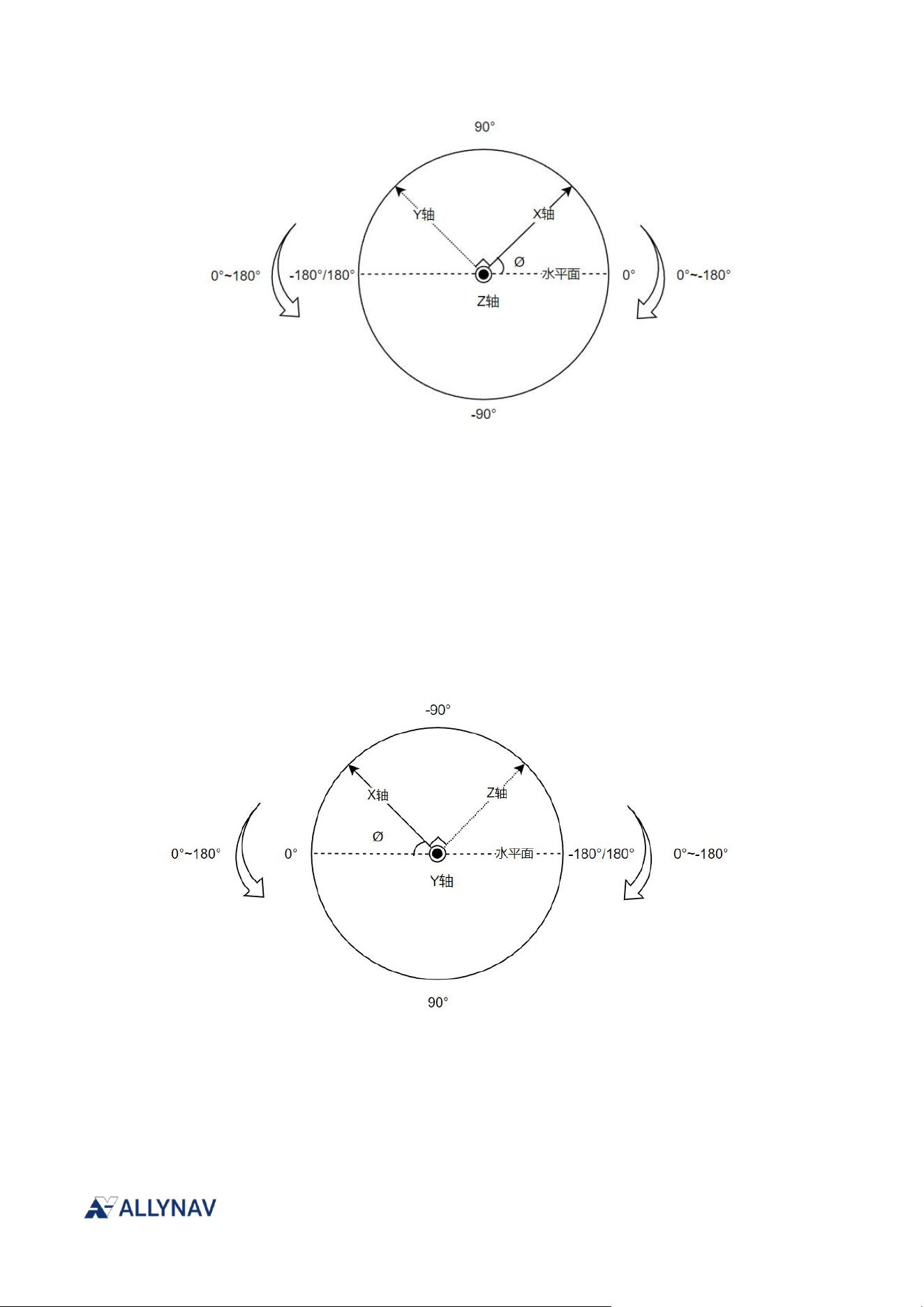
The image below shows a disk perpendicular to the horizontal plane, with the Z-axis parallel to the
horizontal plane. The outward yaw angle perpendicular to the document is Ø, ranging from -180°
to 180°. Values above the horizontal plane are positive, and values below are negative.
R100 Receiver Installation and Operation User Manual V1
4.1.4. Pitch Angle
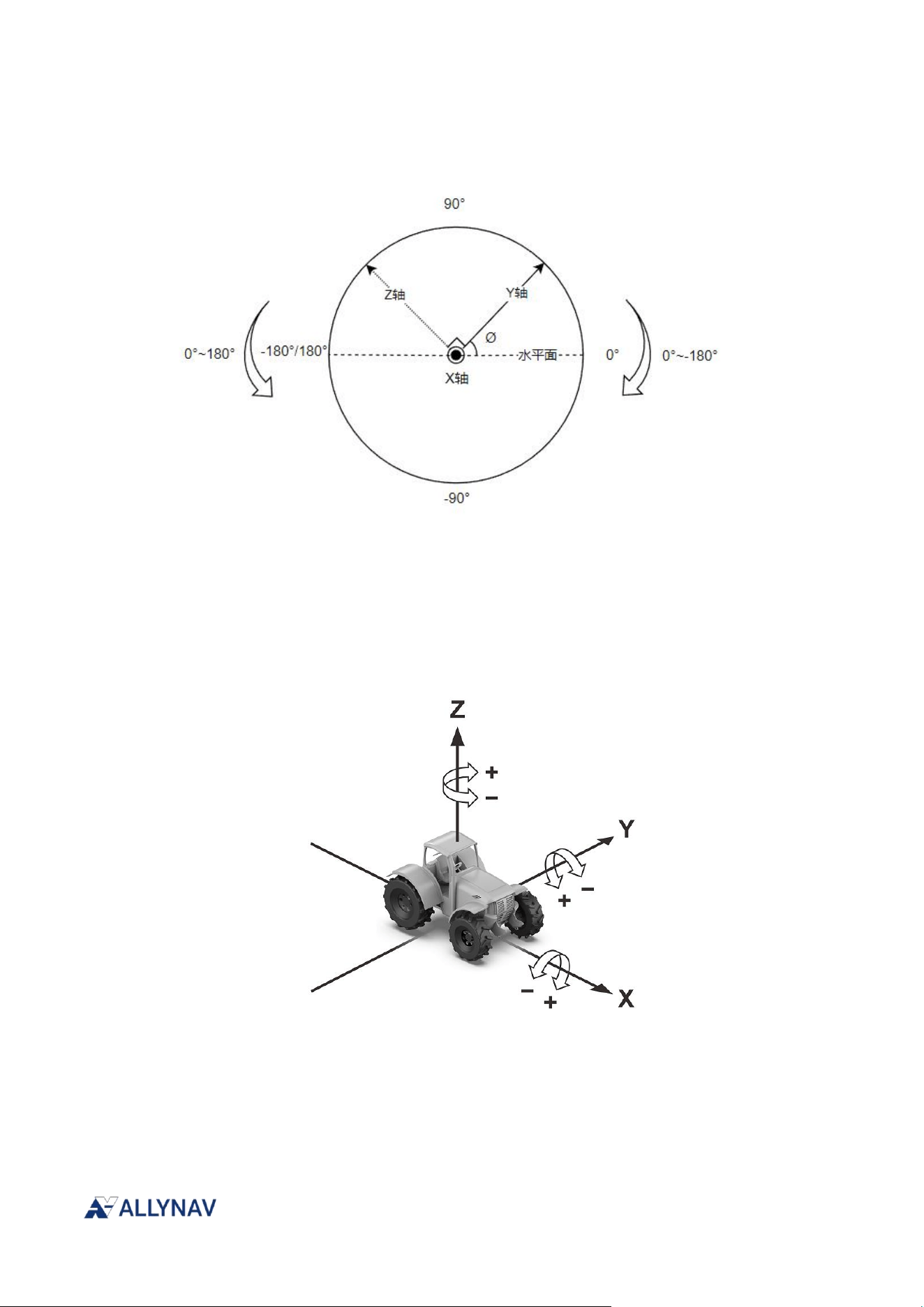
The image below shows the disk surface perpendicular to the horizontal plane, with the dashed line
representing the horizontal plane. The Y-axis is parallel to the horizontal plane and perpendicular
to the document, pointing outwards. The angle between the positive X-axis and the horizontal
plane is the pitch angle Ø, ranging from -180° to 180°. Values
above the horizontal plane are
negative, and values
below are positive.
4.1.5. Roll Angle
The image below shows a circular disk perpendicular to the horizontal plane, with the dashed line
representing the horizontal plane. The X-axis is parallel to the horizontal plane and extends
outwards from the document. The positive Y-axis forms the pitch angle Ø with the horizontal plane,
R100 Receiver Installation and Operation User Manual V1
ranging from -180° to 180°. Values
above the horizontal plane are positive, and values
below are negative.
4.2. Vehicle Navigation Axis Description
The front of the vehicle is aligned with the positive X-axis, the roof with the positive Z-axis, and the
front is facing forward. The right side is aligned with the positive Y-axis. All three axes rotate
clockwise to increase the angle and counter-clockwise to decrease the angle.
4.2.1. Heading Angle
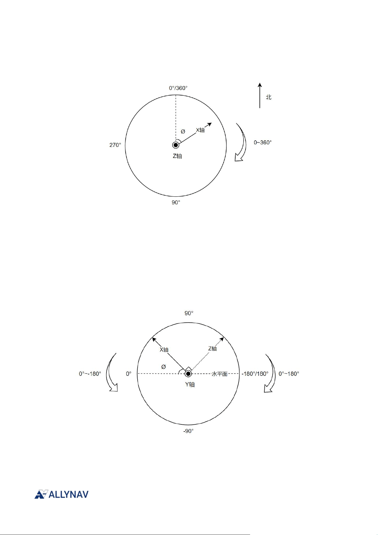
The diagram below shows a circular disk parallel to the horizontal plane. The dashed lines represent
the north-south axis. The Z-axis points upwards and is perpendicular to the horizontal plane,
R100 Receiver Installation and Operation User Manual V1
extending outwards from the document. True north corresponds to 360°/0°. The heading angle is
the angle Ø between the positive X-axis and true north, ranging from 0° to 360°.
4.2.2. Pitch Angle
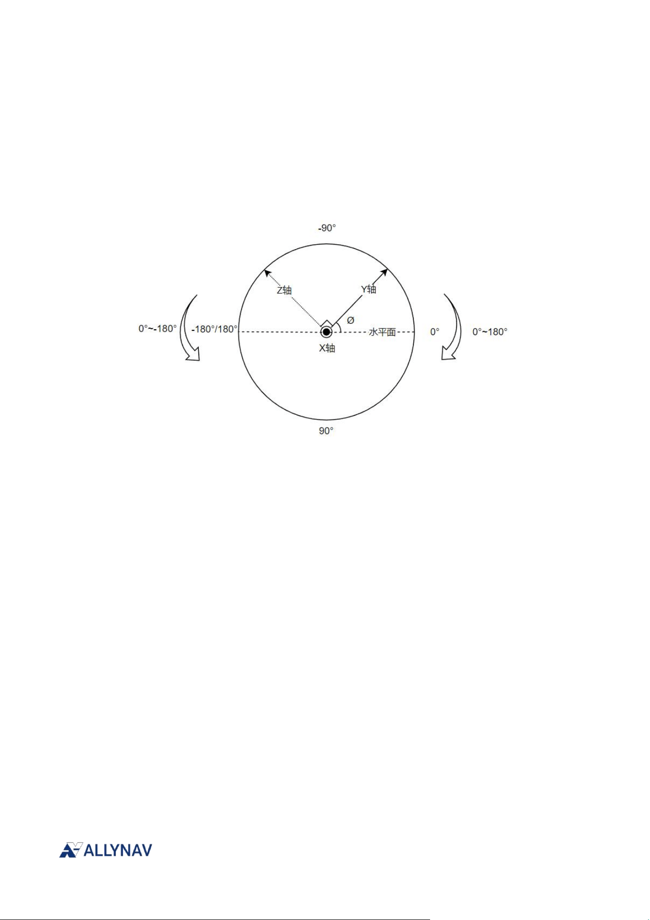
The image below shows a circular disk perpendicular to the horizontal plane, with the dashed line
representing the horizontal plane. The Y-axis is parallel to the horizontal plane and perpendicular
to the document, pointing outwards. The angle between the positive X-axis and the horizontal
plane is the pitch angle Ø, ranging from -180° to 180°. Values
above the horizontal plane are
positive, and values below are negative.
R100 Receiver Installation and Operation User Manual V1
4.2.3. Roll Angle
The image below shows the disk surface perpendicular to the horizontal plane, with the dashed line
representing the horizontal plane. The X-axis is parallel to the horizontal plane and extends
outwards from the document. The positive Y-axis forms the pitch angle Ø with the horizontal plane,
ranging from -180° to 180°. Values
above the horizontal plane are negative, and values
below are positive.
4.3. Software Configuration
Default GNSS configuration required to run integrated navigation algorithms
The GNSS module needs to provide the following configuration to the IMU module:
LOG COM3 GPGGA ONTIME 0.1
LOG COM3 BESTPOSB ONTIME 0.1
LOG COM3 PSRVELB ONTIME 0.1
4.4. Prerequisites
Prerequisites for the effectiveness of integrated navigation algorithms.
4.4.1. Initialization Completion Requirements
Obtaining accurate heading, roll, and pitch angle values requires certain prerequisites.
The state solution in GPGGA is a fixed E4 solution.
The vehicle completes the initialization process by moving forward at a speed of not less

R100 Receiver Installation and Operation User Manual V1
than 1.8 km/h.
5. Chapter 5 GNSS Module
This section only shows some of the main GNSS module configuration commands. Please
download for detailed instructions. “Unicore Reference Commands Manual For N4 High Precision
Products_V2_EN” View the data interface protocol manual.
5.1. Factory default configuration
The following configuration is the default configuration of the R100 receiver when it leaves the
factory.
CONFIG SIGNALGROUP 3 6
CONFIG SIGNALGROUP 3 6
CONFIG SIGNALGROUP 3 6
GPGGA COM2 0.1
GPRMC COM2 0.1
CONFIG NMEA0183 V31
NMEATALKER GP
GPGST COM2 1
GPNTR COM2 1
CONFIG LBAND ENABLE AUTO
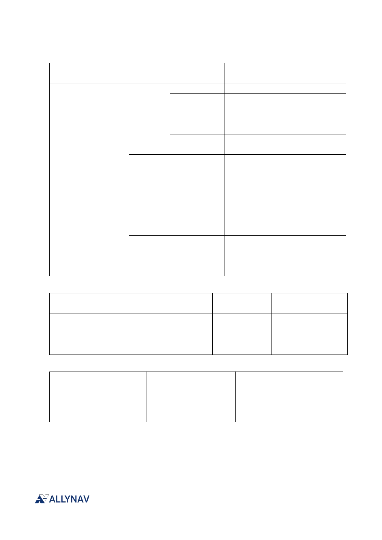
5.2. PPP Configuration
This command is used to configure the receiver's PPP positioning-related functions, and is
supported on certain versions.
command format:
CONFIG PPP [Parameter 1] [Parameter 2] [Parameter 3 (Optional)]
CONFIG PPP CONVERGE [Parameter 1] [Parameter 2]
命令示例:
CONFIG PPP ENABLE B2b-PPP
CONFIG PPP DISABLE
R100 Receiver Installation and Operation User Manual V1
CONFIG PPP CONVERGE 10 20
Command
Header
Function
Name
Parameter
1
Parameter 2
Parameter Description
CONFIG
PPP
ENABLE
B2b-PPP
B2b PPP functionality priority
E6-HAS
E6 HAS Function Priority
AUTO
Automatically select the appropriate
PPP correction number based on the
scenario.
L6MDCPPP
QZSS L6E MADOCA-PPP service
priority
DATUM
WGS84
Reference coordinate system datum
WGS84 coordinate system
PPPORIGINAL
Uses the same coordinate system as
PPP services (default).
TIMEOUT
The value range is 90~180s, with a
default of 120s. When the TIMEOUT is
configured to be 0, the PPP solution
function is turned off.。
CONVERGE
For details on the PPP positioning
accuracy convergence threshold,
please refer to the table below.
DISABLE
PPP function is disabled (default).
Command
Header
Function
Name
Parameter
1
Parameter 2
Parameter 3
(optional)
Parameter Description
CONFIG
PPP
ENABLE
B2b-PPP
ONLY
Only enable B2b-PPP
E6-HAS
Enable E6-HAS only
L6MDCPPP
Enable only QZSS L6E
MADOCA-PPP
Command
Header
Function Name
Parameter 1
Parameter 2
CONFIG
PPP CONVERGE
HorSTD
Horizontal error threshold,
in cm
VerSTD
Elevation error threshold, in cm
5.3. 5.3. LBAND Configuration
The CONFIG LBAND command configures L-band satellite information.
command format:

R100 Receiver Installation and Operation User Manual V1
CONFIG LBAND [Parameter 1] [Parameter 2] [Parameter 3]
Command Examples:
CONFIG LBAND ENABLE AUTO
Command
Header
Function
Name
Parameter
1
Parameter 2
Parameter
Description
Command Header
CONFIG
LBAND
DISABLE
LBAND is off; this is the
default setting.
ENABLE
AUTO
The tracking lobe bundle
and channel are
automatically switched
according to the strategy
module.
BeamID
ID
BeamID can specify an
L-band satellite, which will
be used preferentially for
PPPAR positioning.
This command will not
take effect if BeamID is
not configured.
Value range: Decimal
integer 1 to 7.
DATUM
WGS84
Reference coordinate
system datum WGS84
coordinate
system(default)
LBANDORIGINAL
The coordinate system is
consistent with that of the
service.
BEAM
Parameter set
The parameter set should
include all parameters
shown in Table 4-23,
which describes the
L-band Beam parameter
set configuration, with
each parameter separated
by a single space.
6. Chapter 6 Radio Module
The R100 receiver has a built-in radio module. Before configuring the radio, you need to enter the
pass-through radio mode by sending a command via the CONFIG-RS232 serial port. The
command is as follows:
R100 Receiver Installation and Operation User Manual V1
SYS CONFIG
SET MODE 0
SET CONCOM 14
The command requirements for entering configuration mode for the radio module are as follows:
Configuration mode:
+++
Send the string "+++" (Note: It must be sent in the following manner: One second before
sending the string "+++", no characters can be sent; one second after sending the string "+++", no
characters can be sent, otherwise the system will not be able to enter the radio parameter
configuration mode; there is no newline character (\r\n) at the end of the string).
Exit configuration mode:
ATA
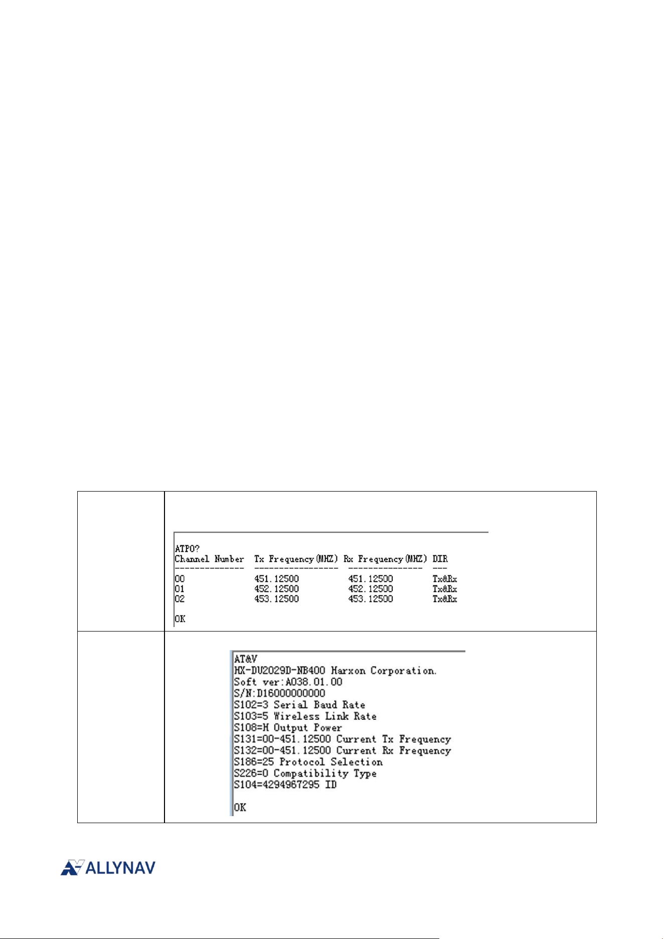
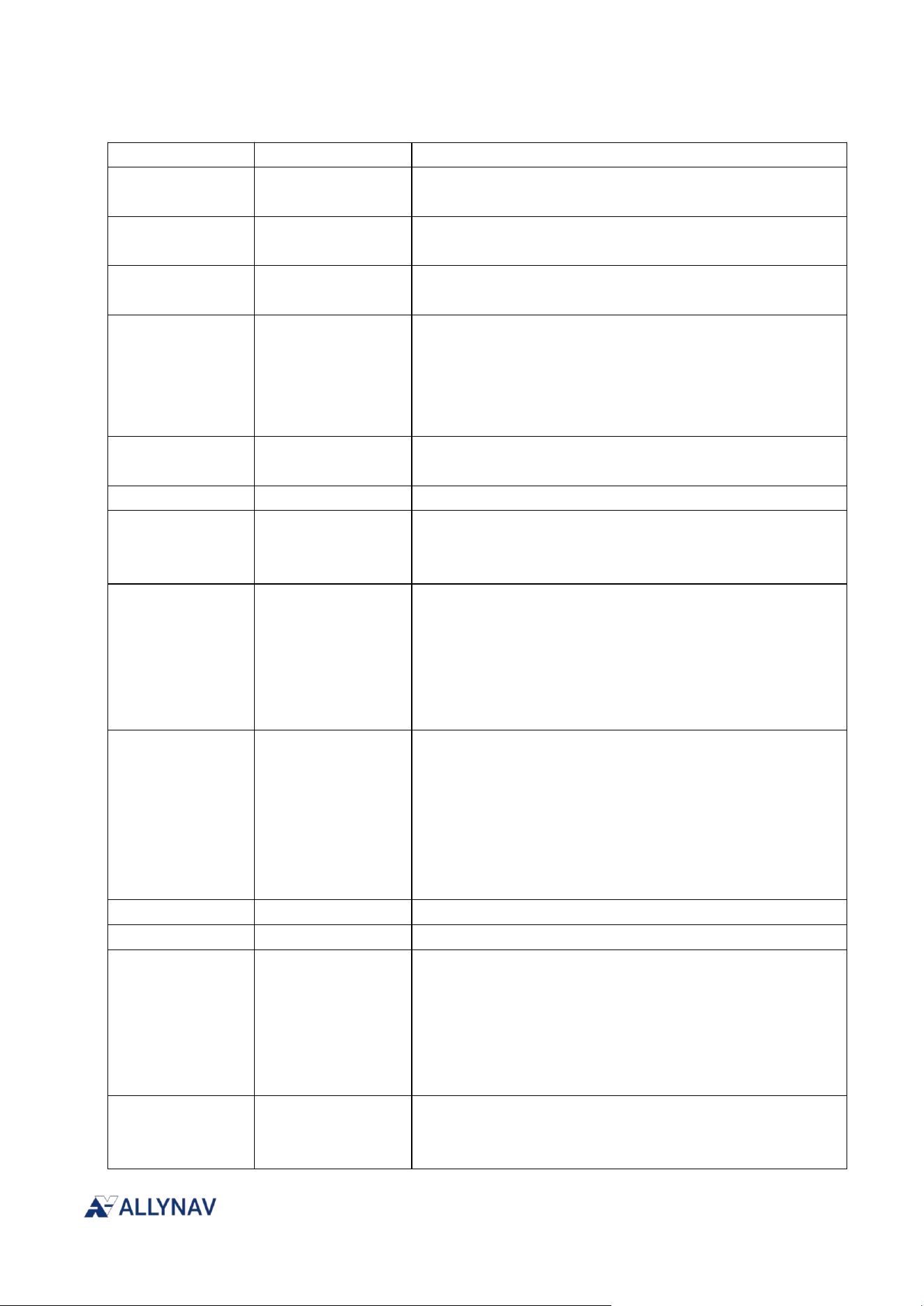
6.1. Factory default configuration
After establishing initial contact with the radio module, you can send the following command to
query the factory settings.
ATP0?
Query the list of operating frequencies already configured for the current radio
station.
AT&V
Query current radio station operating
parameters
R100 Receiver Installation and Operation User Manual V1
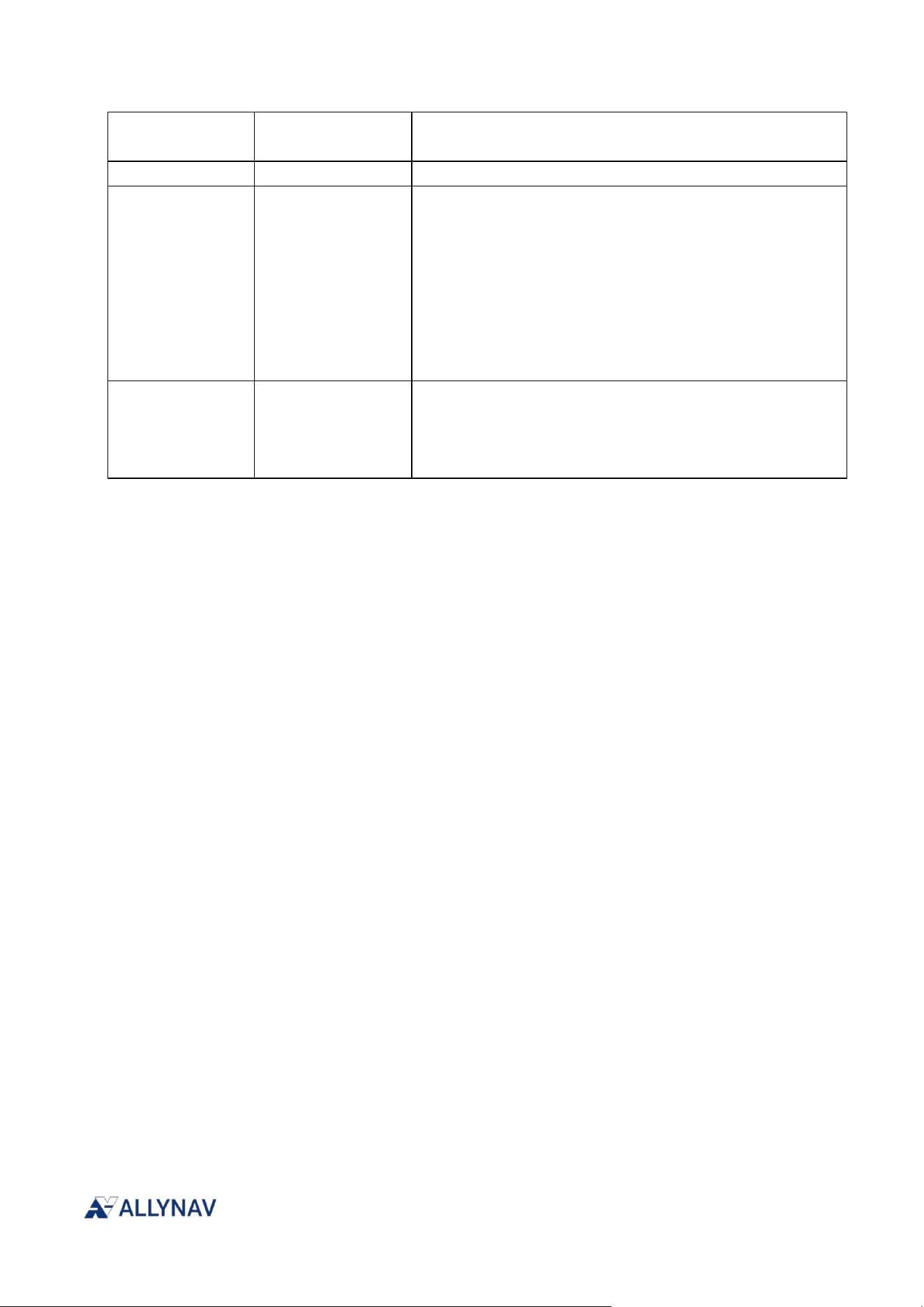
6.2. Configuration Commands
command
value
illustrate
+++
/
Enter configuration mode and send without adding a
carriage return or line feed (\r\n).
ATA
/
Exit configuration mode and add a carriage return and
line feed (\r\n) when sending.
AT&W
/
The parameter save command requires sending a save
instruction after configuration.
ATP0=CH TX RX
TX:410-470MHZ
RX:410-470MHZ
The command to configure the working frequency table
requires that the frequency point and channel number be
separated by a space (only one space character); the
frequency point must retain at least one decimal place
and at most five decimal places.
ATP0?
/
Query the list of operating frequencies already
configured for the current radio station.
AT&V
/
Query current radio station operating parameters
ATS101=value
0:TXONLY
1:DUPLEX
2:RXONLY
Work mode modification
ATS102=value
1:115200
2:57600
3:38400
5:19200
7:9600
The current serial port baud rate has been modified. The
baud rate will take effect immediately after sending this
command. To save the current configuration parameters,
you need to switch the serial port baud rate of the
current configuration tool (SET UARTBD 0,baud) and then
send the AT&W save command.
ATS103=value
0:4800
2:9600
4:19200
5:11000
6:12000
7:15000
8:18000
The air baud rate has been modified. The LIANSHI and
CSS protocols only support air baud rates of 11000,
12000, 15000, and 18000. Other protocols only support
4800, 9600, and 19200.
ATS104=value
0-4294967295
Modify ID parameter
ATS106=value
1-50
Configure the number of network scanning channels.
ATS107=value
0:Disable
networking
function
1:Enable
networking
function
Configure network functions
ATS108=value
H:High power
M:medium power
L:low power
Transmit power modification
R100 Receiver Installation and Operation User Manual V1
ATS131=value
0-63
Current radio station working transmission channel
settings
ATS132=value
0-63
Current radio receiver channel settings
ATS186=value
1:TRIMTALK;
2:TRIMMK3;
4:TT450S
5:TRANSEOT
9:SOUTH
13:SATEL
25:LIANSHI
26:CSS
Communication protocol selection
ATS226=value
0:HARXON;
2:SATEL
4:SINO
5:TOPCON
Compatibility mode selection
Notes: 1. Unless otherwise specified, each AT command must be followed by a carriage return and
line feed (\r\n); 2. To enable communication between two radios, the following parameters must be
consistent: communication protocol, transmit and receive frequencies, and air baud rate.
7. Chapter 7 CAN Bus
CAN bus (Controller Area Network) is a serial communication protocol widely used in automotive
and industrial automation, characterized by high reliability and real-time performance.
7.1. Default Configuration
The CAN baud rate is 500K by default and can be configured to 250K via commands. It defaults to
outputting heading, roll, and pitch data from the IMU integrated navigation algorithm.
7.2. Configure CAN bus baud rate
SYS CONFIG
SET MODE 0
SET CAN 250 // The system will restart after sending. Please wait for the restart to complete
before executing the following commands.
SET MODE 2
SAVE LIST
R100 Receiver Installation and Operation User Manual V1
7.3. AllyNav Messages on CAN
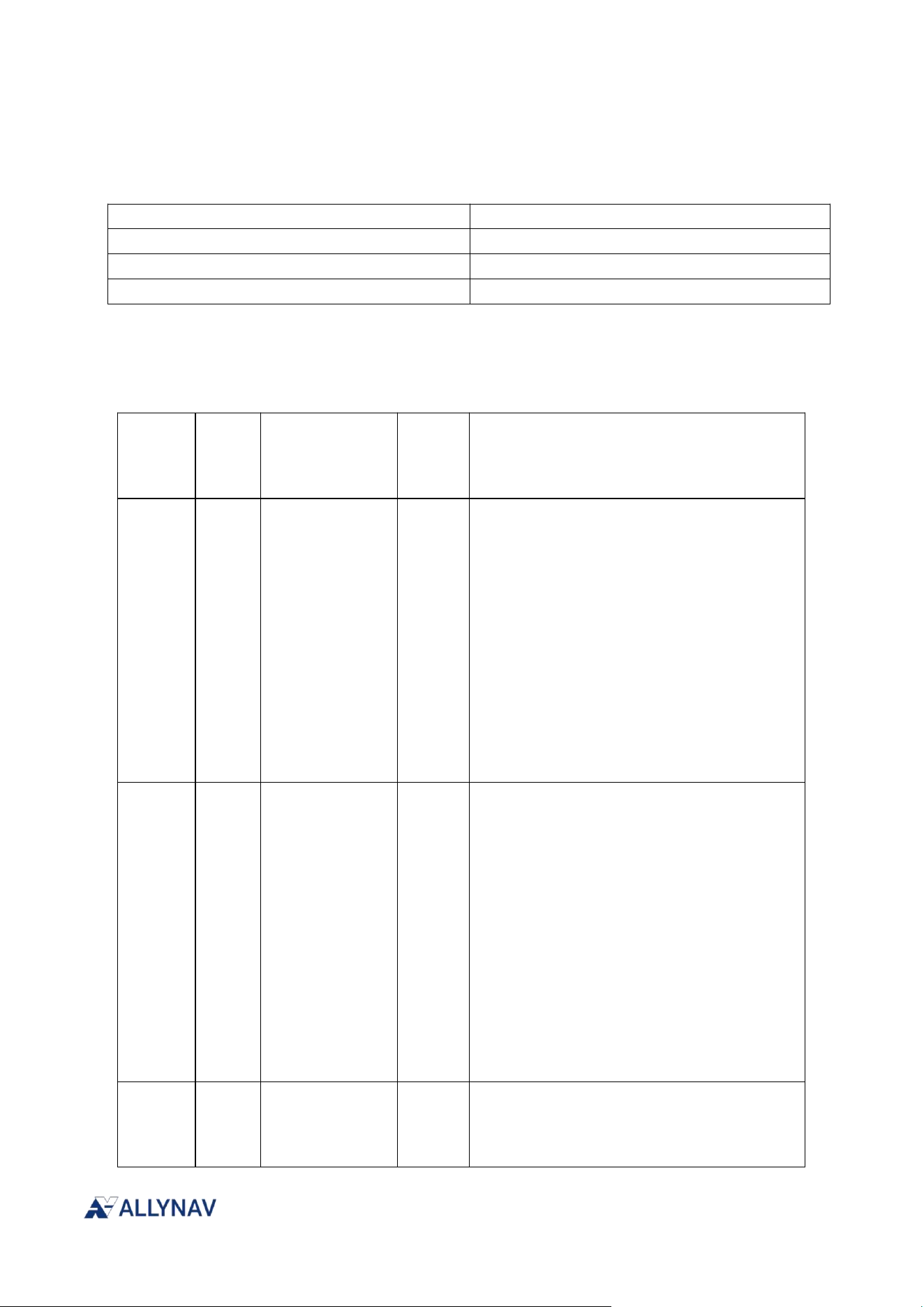
7.3.1. CAN ID
ID
illustrate
0X18FFCA9A
Gyroscope angle data output
0X18FFCB9A
Gyroscope acceleration data output
0X18FFCC9A
Angular rate data output of gyroscope
7.3.2. Angular Velocity Analysis
ID:0X18FFCA9A,Output interval period:200ms
byte.bit
length
Parameter
Name
numerical values
1-2
2
The angle value
of the X-axis
measured by
the attitude
sensor
ROLL
Location: X-axis angle;
Resolution: 0.01°, Offset: 180°;
Range: -180° to 180°;
Calculation Formula
:
=(Data[1]+Data[2]<<8)*0.01°-180°
0xFEFF异常
0xFFFF
无用
3-4
2
The angle value
of the Y-axis
measured by
the attitude
sensor
PITCH
Y-axis angle value;
Resolution: 0.01°, offset 180°
Range: -180°-180°
Calculation
formula:=(Data[3]+Data[4]<<8)*0.01°
-180°
0xFEFF abnormal
0xFFFF useless
5-6
2
The angle value
of the Z-axis
measured by
YAW
Z-axis angle value
Resolution: 0.01°, offset 180°

R100 Receiver Installation and Operation User Manual V1
the attitude
sensor
Range: -180
°
-180
°
Calculation
formula:=(Data[5]+Data[6]<<8)*0.01°
-180°
0xFEFF abnormal
0xFFFF useless
7
1
0xFF
FF:Initialization not completed
No FF:Initialization complete
8
1
0xFF
7.3.3. Acceleration Analysis
ID:0X18FFCB9A,Output interval period:50ms
The standard IMU firmware version does not support output; a special version is required.
byte.bit
length
Parameter
Name
numerical values
1-2
2
The attitude
sensor
measures the
acceleration
along the
X-axis.
Acceleration along the X-axis;
Resolution: 0.00025g, offset 8g
Range: -8g~8g
Calculation
formula:=(Data[1]+Data[2]<<8)*0.00025-8
g
0xFEFF abnormal
0xFFFF useless
3-4
2
The attitude
sensor
measures the
acceleration
along the
Y-axis acceleration;
Resolution: 0.00025g, offset 8g
Range: -8g~8g
Calculation formula:

R100 Receiver Installation and Operation User Manual V1
Y-axis.
=(Data[3]+Data[4]<<8)*0.00025-8g
0xFEFF abnormal
0xFFFF useless
5-6
2
The attitude
sensor
measures the
acceleration
along the
Z-axis.
Z-axis acceleration;
Resolution: 0.00025g, offset 8g
Range: -8g~8g
Calculation formula:
=(Data[5]+Data[6]<<8)*0.00025-8g
0xFEFF abnormal
0xFFFF useless
7-8
2
reserve
0xFFFF
7.3.4. Angular Rate Analysis
ID:0X18FFCC9A,Output interval period:50ms
byte.bit
length
Parameter
Name
numerical values
1-2
2
The attitude
sensor
measures the
angular rate
along the
X-axis.
Gyro_x
Angular velocity along the X-axis;
Resolution: 0.02°, offset 640°/s
Range: -640°/s ~ 640°/s
Calculation
formula:=(Data[1]+Data[2]<<8)*0.02-640°/
s
0xFEFF abnormal
0xFFFF useless
3-4
2
The attitude
sensor
measures the
angular rate
Gyro_y
Y-axis angular velocity;
Resolution: 0.02
°
, offset 640
°
/s
Range: -640
°
/s~640
°
/s
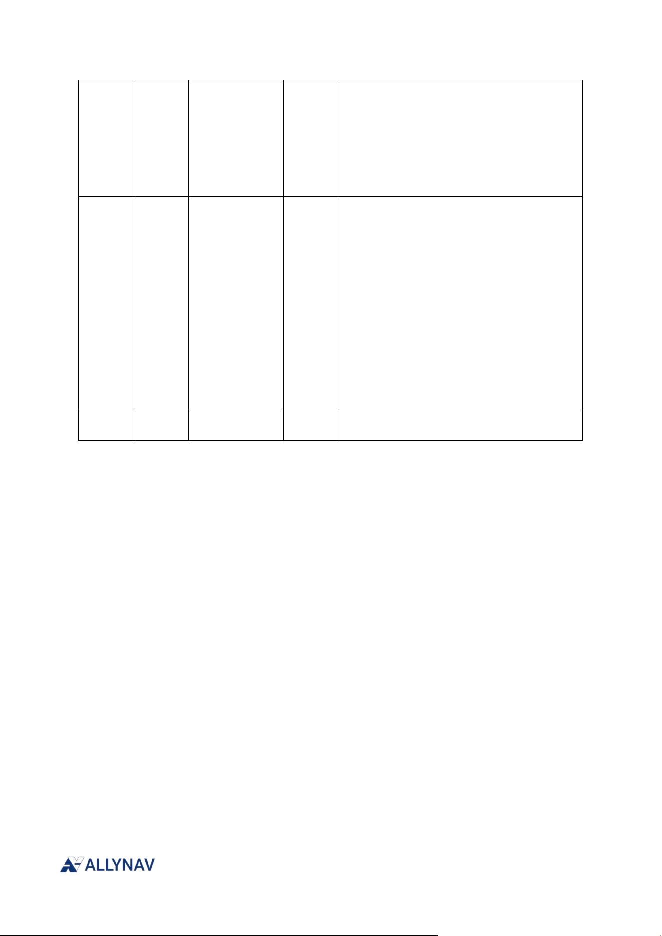
R100 Receiver Installation and Operation User Manual V1
along the
Y-axis.
Calculation formula:
=(Data[3]+Data[4]<<8)*0.02-640
°
/s
0xFEFF abnormal
0xFFFF useless
5-6
2
The attitude
sensor
measures the
angular rate
along the
Z-axis.
Gyro_z
Z-axis angular velocity;
Resolution: 0.02
°
, offset 640
°
/s
Range: -640
°
/s~640
°
/s
Calculation
formula:=(Data[5]+Data[6]<<8)*0.02-640
°
/
s
0xFEFF abnormal
0xFFFF useless
7-8
2
reserve
0xFFFF
8. Chapter 8 Fault Diagnosis
The diagnostic function is a series of mechanisms that enable self-testing and status monitoring of
the receiver during startup, operation, and maintenance. It combines periodic self-testing with
event triggering to sample and analyze key hardware parameters such as onboard temperature,
voltage, and module status in real time. During initialization, the system performs a comprehensive
self-test to ensure all modules are within their normal operating range. During normal operation,
the diagnostic program, as an independent thread or process, continuously monitors these
parameters and reports any abnormalities to other working units. When a parameter exceeds a
preset threshold, the system automatically implements protective measures, such as reducing CPU
frequency or shutting down module power. Furthermore, the diagnostic function supports external
command queries and can output detailed status reports via serial port or bus interface, facilitating
debugging and maintenance.
8.1. Functional Classification
The purpose of creating module or function indexes is to facilitate unified management,
improve compatibility, and reduce parsing difficulty by using single numbers instead of strings,
such as using 1 to represent "GNSS". The indexes are divided into three categories: the first
R100 Receiver Installation and Operation User Manual V1
category represents the physical module, the second category represents the corresponding
physical quantity, and the third category represents the diagnostic status. If the equipment has
special requirements, the index can be decremented from 255, allowing for differentiated
configurations for different devices, depending on the specific functional requirements of the
device.
8.1.1. Module Classification Description
Serial
Number
Module Description
Remark
0
Reserve
1
MainBoard
Device motherboard
2
MCU
3
GNSS
4
IMU
5
RADIO
6
4G
7
BLUETOOTH
8
WIFI
9
POWER1
Power supply
(lead-acid/lithium
battery)
10
POWER2
Solar energy
…
253
Custom Module 3
254
Custom Module2
255
Custom Module1
Note: Some definitions are not applicable to R100.
8.1.2. Description of physical quantities
Serial Number
Function Description
Remark
0
Reserve
1
Temp
2
Voltage
3
Current
4
PWMfreq
5
PWMduty
6
CSQ
Signal quality
7
SNR
Signal-to-noise ratio
8
MsgID
Message ID
…
253
Custom physical
R100 Receiver Installation and Operation User Manual V1
quantities 3
254
Custom physical
quantities 2
255
Custom physical
quantities 1
8.1.3. Diagnostic Status Description
Serial
Number
Function
Description
Remark
0
Reserve
Reserve
1
OK
normal
2
OverLimit
Exceeding the set
threshold limit
3
BelowLimit
Below the set threshold
lower limit
4
NoSignal
No waveform or signal
detected
5
NoID
No corresponding ID
detected
…
253
Custom status 3
254
Custom status 2
255
Custom status 1
8.2. Print diagnostic text information
[CONFIG-RS232] GET DIAGTXT
The above information is printed via serial port to facilitate troubleshooting by on-site
personnel. It includes the following content:
1. Module classification information
2. Physical quantity information
3. Diagnostic status information
4. Information on the reporting interval of the status of each physical quantity
Note: In all the diagnostic information below, 'm' (module) represents the module category
number, 'p' (physical quantity) represents the physical quantity, and 's' (status) represents the
diagnostic status.

R100 Receiver Installation and Operation User Manual V1
8.3. Configure diagnostic information time intervals by second
[CONFIG-RS232]SYS DIAGTS m,p[,time]
time Optional instruction
1. When the `time` parameter is omitted, it indicates that the host computer is requesting time
interval information for a specified module and function from the slave device. The receiver will
return the relevant time information immediately upon receiving the instruction.
2. When the `time` parameter is included, it indicates that the host computer sets the
diagnostic information reporting interval for the receiver. (Note that before using the setting
command, you need to send `SYS CONFIG` to unlock it first.)
time Data types unsigned int, unit s
For example:
1. The host computer automatically reports the temperature diagnostic information obtained
from the MCU at intervals.
host computer:SYS DIAGTS 2,1
2. The host computer is configured to report temperature diagnostic information from the
MCU at a time interval of 1 second.
host computer:SYS DIAGTS 2,1,1
8.4. Configure diagnostic information time intervals in milliseconds
[CONFIG-RS232] SYS DIAGTMS
Format:SYS DIAGTMS m,p[,time]
time Optional instruction
1. When the `time` parameter is omitted, it indicates that the host computer is requesting time
interval information for a specified module and function from the slave device. The receiver will
return the relevant time information immediately upon receiving the instruction.
2. When the `time` parameter is included, it indicates that the host computer sets the
diagnostic information reporting interval for the receiver. (Note: Before using the setting
command, you need to send `SYS CONFIG` to unlock the receiver first.)
time Data types unsigned int, unit s
For example:
1. The host computer automatically reports the temperature diagnostic information obtained

R100 Receiver Installation and Operation User Manual V1
from the MCU at intervals.
host computer:SYS DIAGTMS 2,1
2. The host computer is configured to report temperature diagnostic information from the
MCU at a time interval of 1000ms.
host computer:SYS DIAGTMS 2,1,1000
8.5. Configure diagnostic information time intervals by frequency
[CONFIG-RS232] SET DIAGFS m,p[,freq]
freq Optional instruction。
1. When the `freq` parameter is omitted, it indicates that the host computer is requesting
frequency information for a specified module and function from the slave device. The receiver
will immediately return the relevant frequency information upon receiving the instruction.
2. When the `freq` parameter is included, it indicates that the host computer sets the diagnostic
information reporting frequency of the receiver. (Note that before using the setting command,
you need to send `SYS CONFIG` to unlock it first.)
freq Data types unsigned int, unit Hz
For example:
1. The host computer obtains the temperature diagnostic information from the MCU and
automatically reports the frequency.
host computer:SYS DIAGFS 2,1
2. The host computer is configured to report temperature diagnostic information to the MCU
at a time interval of 1Hz.
host computer:SYS DIAGFS 2,1,1
8.6. Real-time access to diagnostic information
[CONFIG-RS232] GET DIAGIF m,p
For host computer operators, when clicking a button or needing to immediately obtain
relevant diagnostic information.
The diagnostic information returned by this command will not reset the diagnostic information
reporting interval counter mentioned in the previous command. For example, if the interval for
reporting a certain diagnostic information is configured to be once per second, and 300ms has

R100 Receiver Installation and Operation User Manual V1
passed since the last report, pressing the retrieval button will immediately return a diagnostic
information.
However, the interval will continue to count from the 300ms that have already elapsed, and will
not be reset to 0ms.
For example:
1. Read the voltage signal of the GNSS module
GET DIAGIF 3,2
2. Read PWM sampling information
GET DIAGIF 1,4
The following is the content reported by the lower-level machine. It is divided into two types.
1. SDH(System Diagnose Human-Readable) It is mainly used by on-site inspectors to read
data; the serial port will print the content represented by strings in the table above.
Example: Report GNSS power supply voltage 3.3V
SDH 3,2,3.3
2. SDM(System Diagnose Machine-Parseable) Primarily used for host computer parsing,
reducing data volume and improving parsing efficiency. The string reference section
categorizes string descriptions.
Example: Report GNSS power supply voltage 3.3V
SDM GNSS,Voltage,3.3
8.7. Report diagnostic information
[CONFIG-RS232] SDH/SDM DIAGIF (m,p,para1,para2…)(…)
Diagnostic content reported by the lower-level machine after being triggered immediately or
periodically.
illustrate:
1. The data type of `para` is uniquely determined by the `m` module class, the `p` physical
quantity class, and the product requirements. For example, the temperature value of GNSS is of
type `float`.
2. The number of parameters para1, para2...parax is uniquely determined by the module class
m, the physical quantity class p, and the product requirements.

R100 Receiver Installation and Operation User Manual V1
3. One or more diagnostic records can be uploaded simultaneously; each diagnostic record is
called a data set. Data within a group is separated by commas, and multiple groups are
separated by commas (without any characters in between).
For example:
1. GNSS 温度值 42.3
SDH DIAGIF 3,1,42.3
SDM DIAGIF GNSS,Temp,42.3
2. GNSS temperature: 42.3°C, voltage: 3.3V
SDH DIAGIF (3,1,42.3)(3,2,3.3)
SDM DIAGIF (GNSS,Temp,42.3)(GNSS,Voltage,3.3)
3. The three temperature points on the motherboard are 40.1, 40.2, and 40.3.
SDH DIAGIF 1,1,40.1,40.2,40.3
SDM DIAGIF Mainboard,Temp, 40.1,40.2,40.3
The following are alarm information reports.
The command header SDE indicates system diagnose error.
8.8. Diagnostic Alarms
[CONFIG-RS232] SDH/M DIAGERR m,s,p
When the downstream device triggers the alarm mechanism, it immediately sends diagnostic
alarm information to the upstream device. Simultaneously, the system periodically checks its
status; if abnormalities persist, it will periodically report error statuses at configured time
intervals. Once the status returns to normal, the device will send a message containing an "OK"
status, and the alarm will be cleared.
Example:
1. GNSS temperature exceeded limit
SDH DIAGERR GNSS,Temp,OverLimit
SDM DIAGERR3,1,2
2. CAN bus error, no corresponding IMU ID
SDH DIAGERR IMU,MsgID,NoID

R100 Receiver Installation and Operation User Manual V1
SDM DIAGERR 4,8,5
3. CAN bus fault clearing
SDH DIAGERR IMU,MsgID,OK
SDM DIAGERR 4,8,1
8.9. Set alarm limit
[CONFIG-RS232] SET DIAGEUL m,p,value
This indicates that `diagnos err upper limit` is used to indicate the error rate.
When the program detects that a physical quantity value is higher than the upper limit, it will
immediately report it. Afterward, it will report periodically without resolving the status quo.
For example:
Set the GNSS voltage value to no more than 3.5V.
SET DIAGEUL 3,2,3.5
8.10. Set alarm lower limit
[CONFIG-RS232] SET DIAGELL m,p,value
Indicates diagnostics err lower limit
When the program detects that a physical quantity value is below the lower limit, it will
immediately report it. Afterward, it will report periodically without resolving the status quo.
For example:
Set the GNSS voltage value to no less than 3.1V.
·SET DIAGELL 3,2,3.1
8.11. Read the upper and lower alarm limits
[CONFIG-RS232] GET DIAGELT m,p
This indicates the diagnose err limit.
Obtain the threshold information of a certain physical quantity
Example: Reading the upper and lower limit alarm thresholds of GNSS voltage.
GET DIAGELT 3,2

R100 Receiver Installation and Operation User Manual V1
8.12. Configure and enable diagnostic alarms
[CONFIG-RS232] SYS DIAGETS m,p[,time]
Enable or disable diagnostic error alarm function
time Optional instruction
1. When the `time` parameter is omitted, it indicates that the host computer is requesting time
interval information for a specified module and function from the slave device. The receiver will
return the relevant time information immediately upon receiving the instruction.
2. When the `time` parameter is included, it indicates that the host computer sets the reporting
interval for diagnostic alarm information from the receiver. A `time` value of 0 (in seconds)
indicates that the diagnostic alarm function is disabled. A value greater than 0 indicates the
reporting interval after triggering the alarm threshold. (Note: Before using the setting
command, you need to send `SYS CONFIG` to unlock the system.)
For example:
1. Disable GNSS voltage diagnostic alarm function
SYS DIAGETS GNSS,Voltage,0
SYS DIAGETS 3,2,0
2. Set the GNSS voltage alarm reporting interval to 1 second.
SYS DIAGETS GNSS,Voltage,1
SYS DIAGETS 3,2,1
illustrate:
Diagnostic status reporting and diagnostic alarm reporting should be distinguished.
To enable/disable status reporting, use the SYS DIAGTS/SYS DIAGTMS/SYS DIAGFS
commands.
To enable or disable alarm reporting, use SYS DIAGETS.
8.13. Read all CAN bus message IDs
[CONFIG-RS232] GET CANID [time]
`time` is an optional parameter. The unit is seconds.
When the instruction does not include a time period, the program defaults to detecting all
message IDs on the bus within 2 seconds.
R100 Receiver Installation and Operation User Manual V1
When the instruction includes "time", the program will detect all message IDs on the bus within
the specified time period.
Return content:@GET CANID n,ID1,ID2…
The returned message ID is displayed in hexadecimal format.
9. Chapter 9 Firmware
9.1. Firmware Updates and Model Upgrades
9.1.1. Firmware Update
The R100 series receivers support firmware upgrades using common serial port tools such as
SecureCRT.
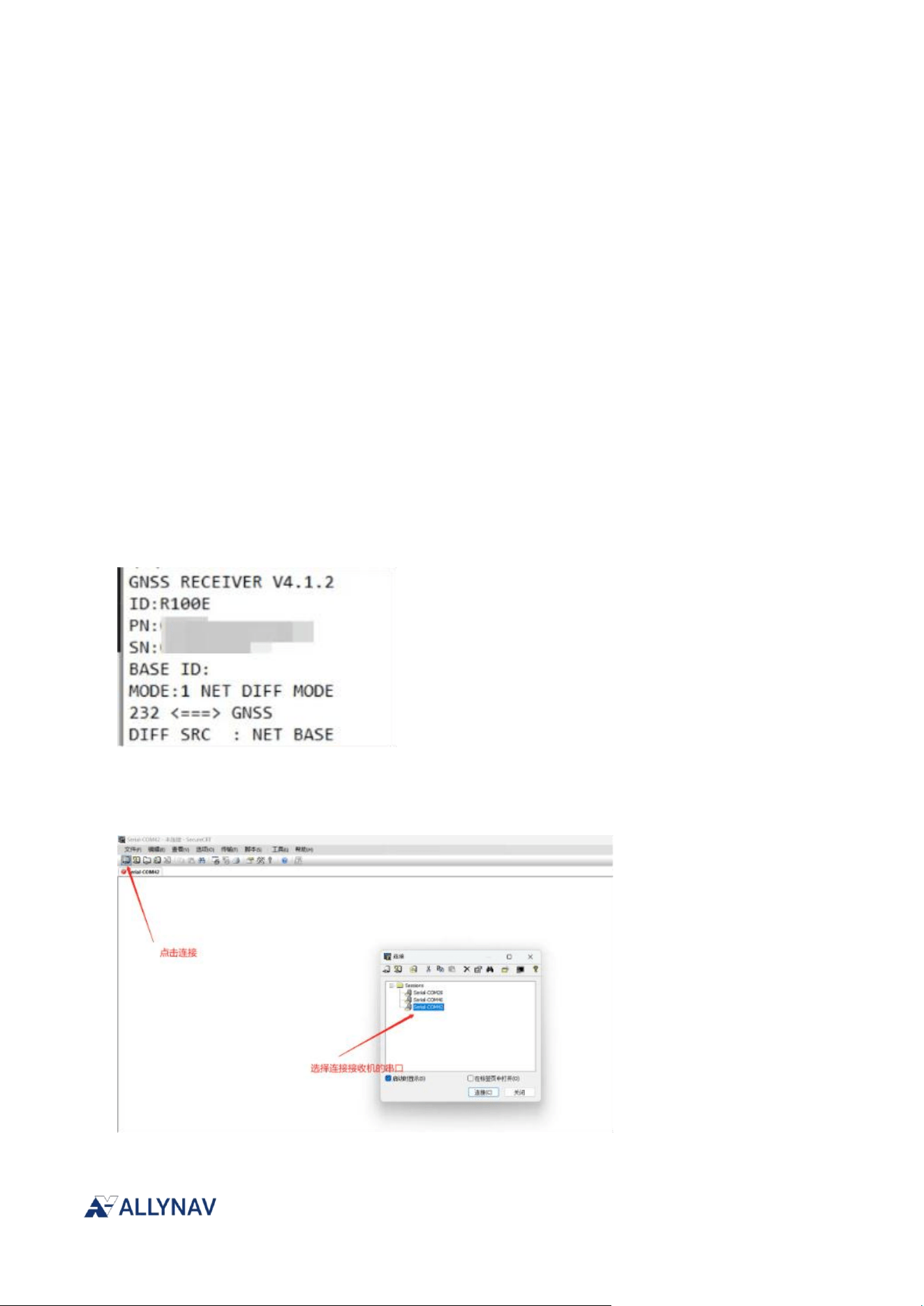
Connect the receiver to CONFIG-RS232 using a DB9 cable, and send SYS SAVE to view the current
firmware version V4.1.2.
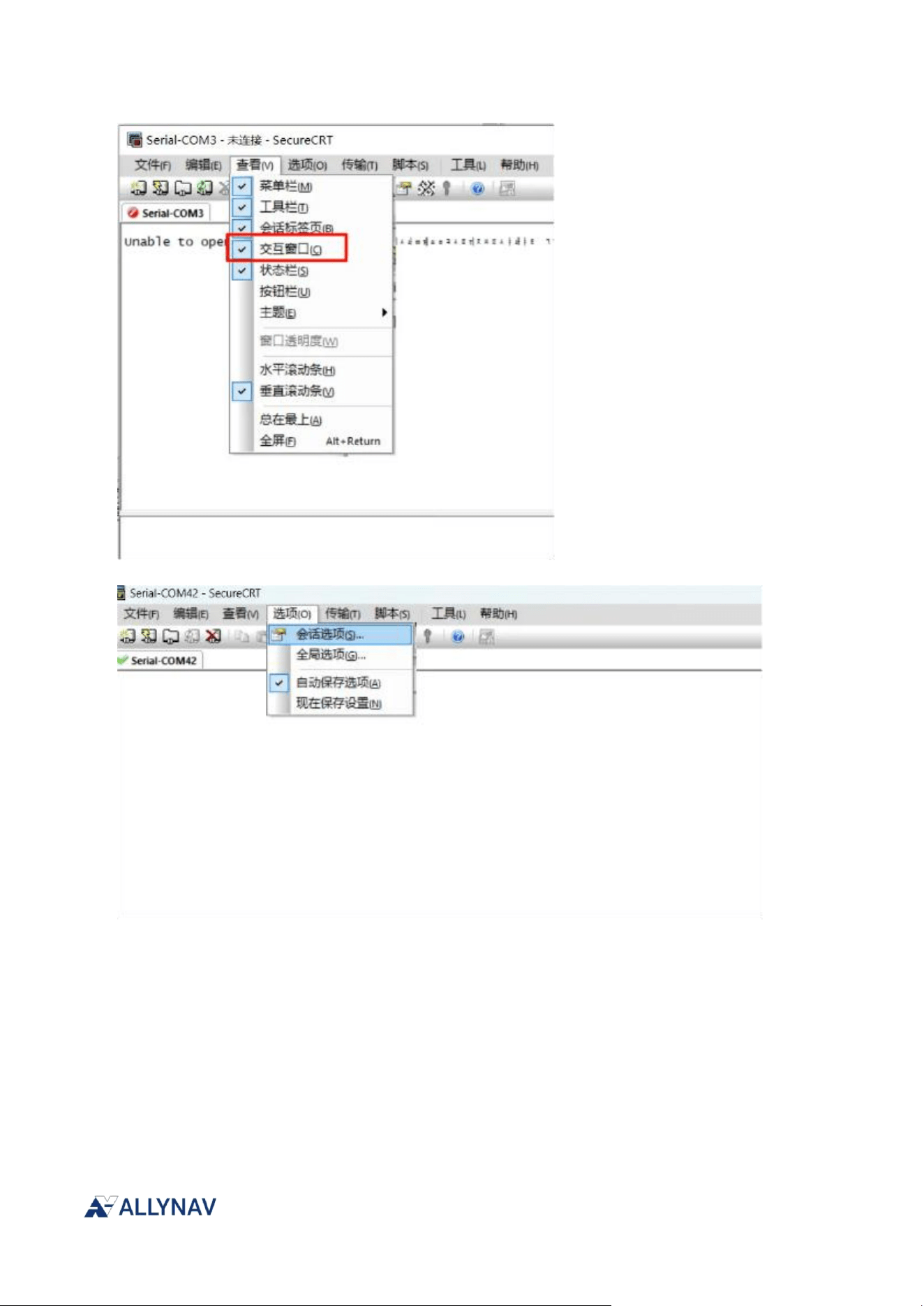
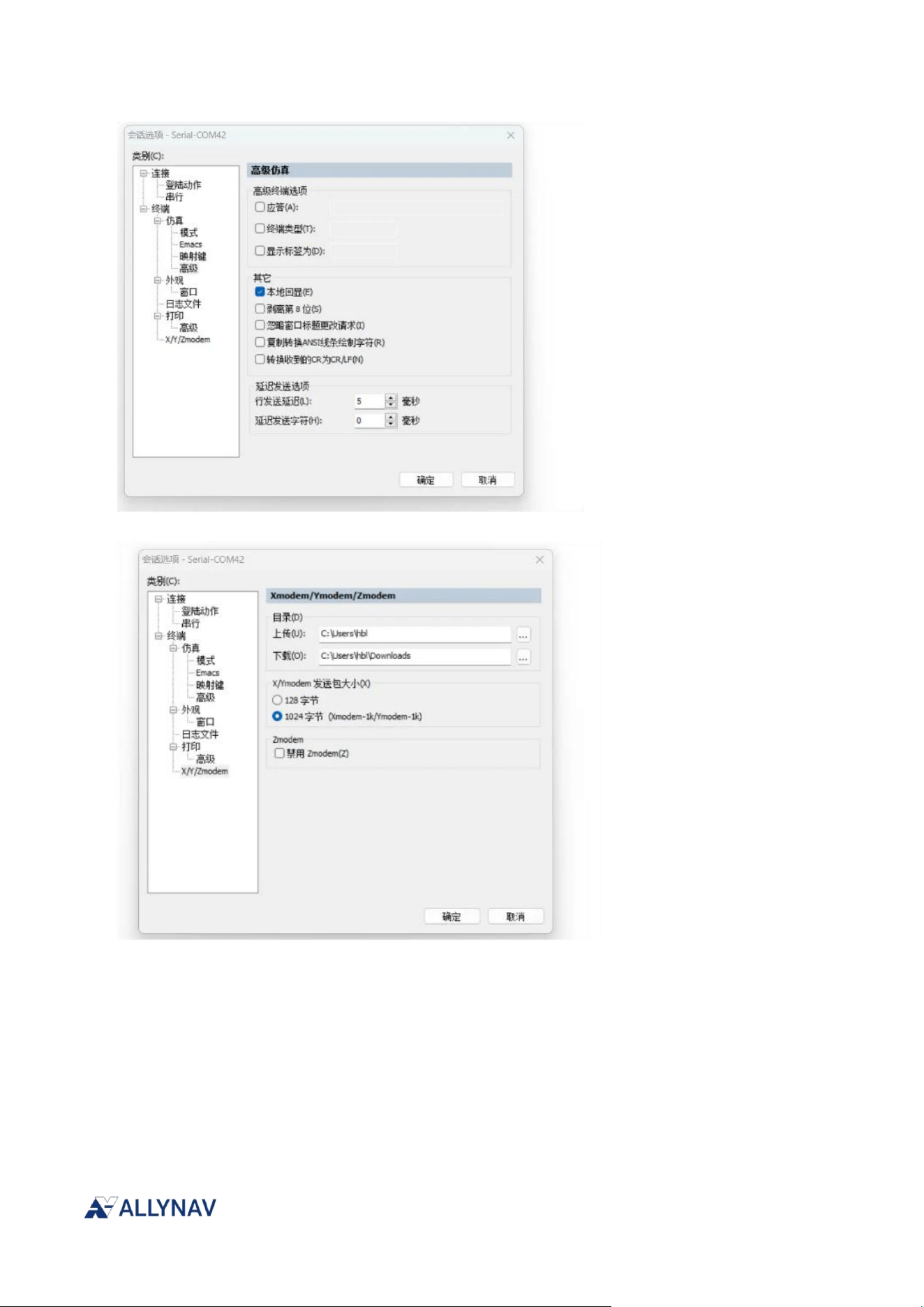
Open the secureCRT.exe software, select the COM port corresponding to the receiver's serial port,
connect, and configure the serial port properties.
R100 Receiver Installation and Operation User Manual V1

R100 Receiver Installation and Operation User Manual V1
R100 Receiver Installation and Operation User Manual V1
After clicking OK, enter the following command in the interactive window below and wait for the
following image to appear.
SYS CONFIG
SET MODE 6
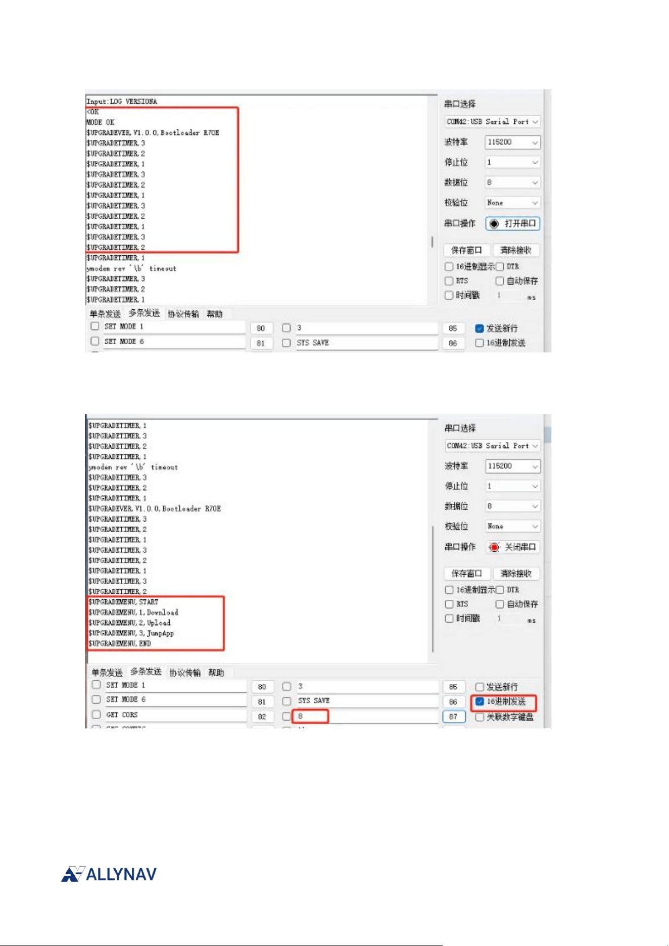
R100 Receiver Installation and Operation User Manual V1
Press the backspace key on your keyboard to see the menu list, then send 1 to enter firmware
upgrade mode.
The window will then continuously print the character 'C'. Select the transmission option shown in
the image below, and then select send (ymodem).
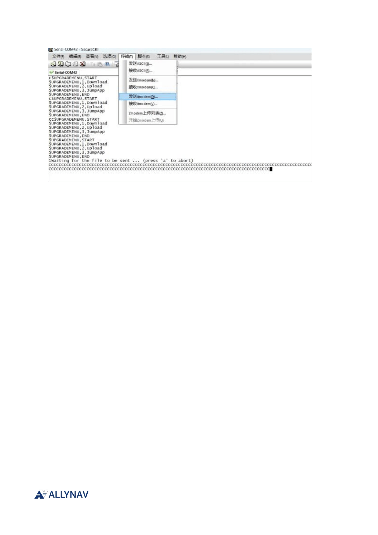
R100 Receiver Installation and Operation User Manual V1
Select the fota.pac file, select "Add A", and select "OK". Sending will then begin. The progress
percentage will be displayed on the screen.
9.1.2. Firmware Downgrade
R100 series receivers do not support firmware downgrading.
9.2. Download firmware file
Please contact business or technical support for the latest upgrade files.
9.2.1. Firmware File Format
Firmware upgrade files for the R100 series receivers all have the .pac extension.
9.3. Use QFlash to update or upgrade
After launching the QFlash tool, the main interface is shown in the following figure.
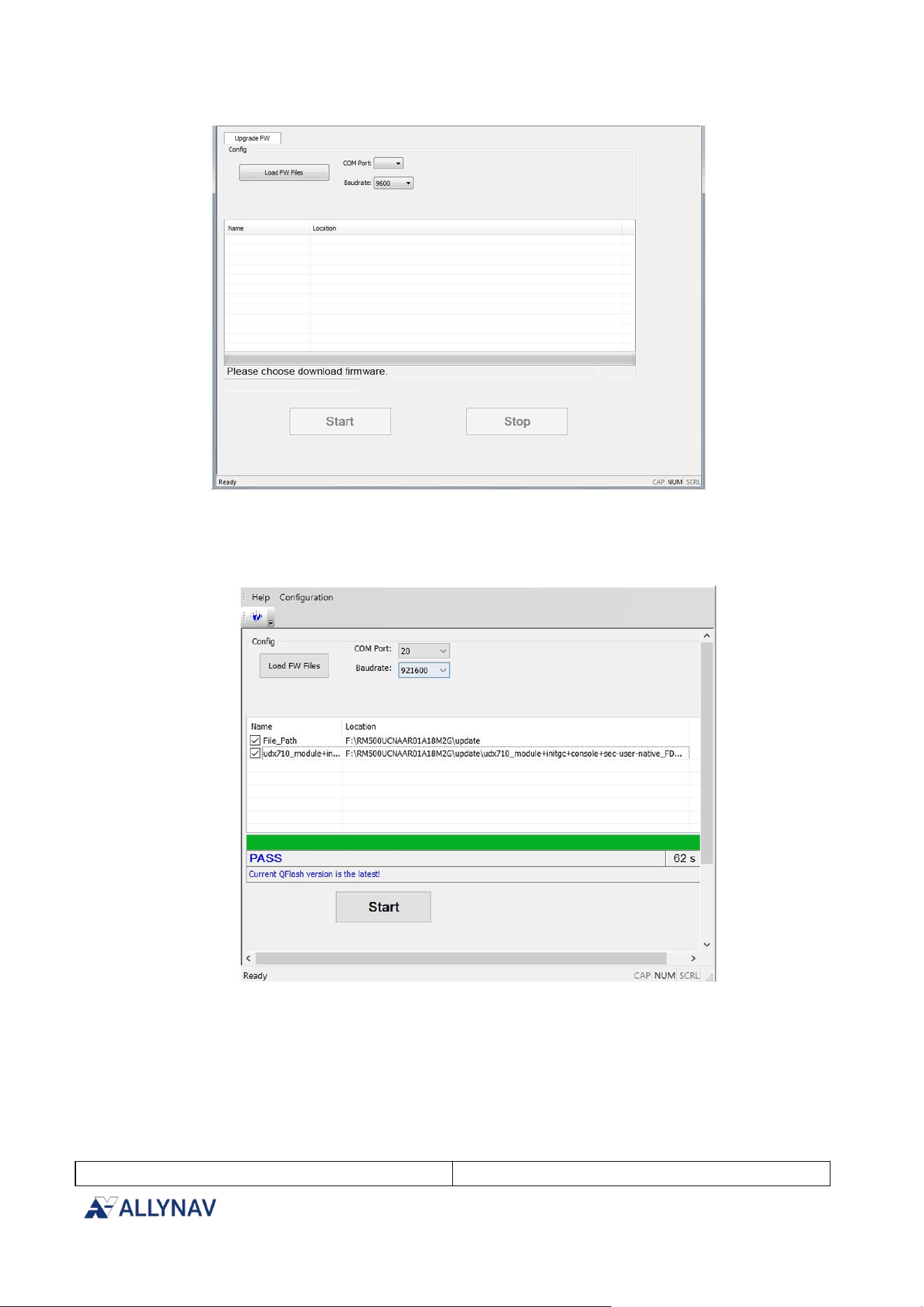
R100 Receiver Installation and Operation User Manual V1
Select the serial port corresponding to the Quectel USB AT Port. To find the AT port number, please
go to Device Manager on your PC, as shown in the image below.
Appendix A R100 Technical Specifications
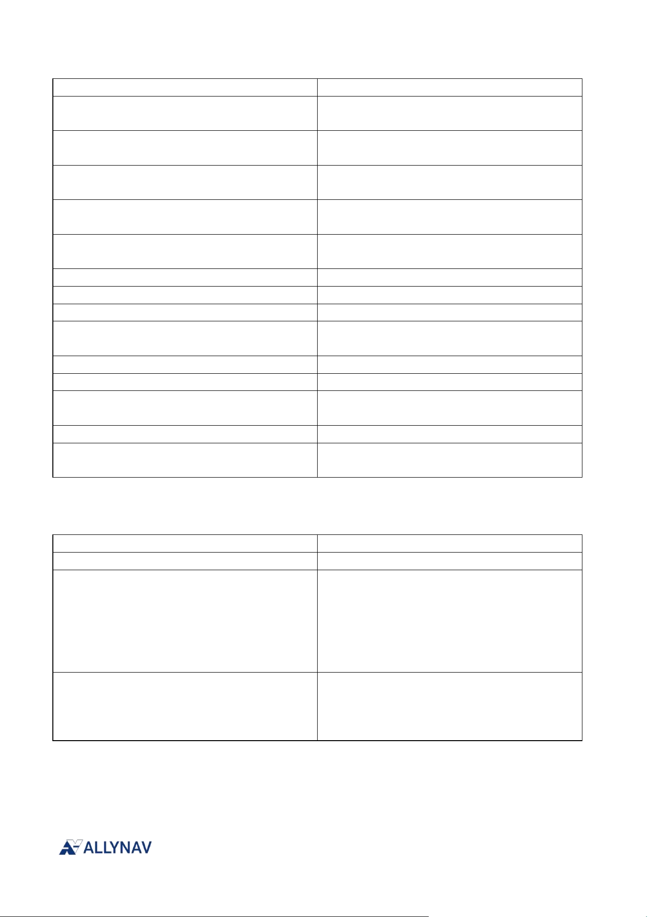
A.1 R100 Performance Specifications
GNSS positioning accuracy
1
Single point positioning (RMS)
2
flat:1.5 m
R100 Receiver Installation and Operation User Manual V1
Elevation:2.5 m
DGPS (RMS)
2,3
flat:0.4 m+1 ppm
Elevation:0.8 m+1 ppm
RTK (RMS)
2,3
flat:0.8 cm+1 ppm
Elevation:1.5 cm+1 ppm
PPP (RMS)
4
flat:5 cm
Elevation:10 cm
PPP-AR(RMS)
4
flat:3 cm @ 5 min
Elevation:6 cm @ 5 min
CLAS(RMS)
4
flat:5 cm @ 1 min
Elevation:10 cm @ 1 min
Orientation accuracy (RMS)
7
0.1 degrees/1 m baseline
PPS 精度(RMS)
20 ns
速度精度(RMS)
5
0.03 m/s
First positioning time
6
cold start<30 s
warm start<4 s
Initialization time
2
<5 s (Typical value)
Initial reliability
2
>99.9%
Data update rate
Positioning and Orientation 20 Hz
20 HzOriginal observations
Differential data
RTCM 3.X
Data format
NMEA - 0183
Unicore
satellite frequency
aisle
1408 channels, based on Nebulas IV
TM
constellation
BDS、GPS、GLONASS、Galileo、QZSS
Main antenna frequency
BDS: B1I, B3I, B2a, B2b
GPS: L1C/A、L2P (Y)/L2C、L5
GLONASS: G1、G2
Galileo: E1、E5a、E5b、E6
QZSS: L1C/A、L1C/B、L2C、L5、L6
L-Band
From antenna frequency
BDS: B1I, B3I
GPS: L1C/A、L2C
Galileo: E1、E5b
QZSS: L1C/A、L2C
1. This section covers the main antenna performance of the UM982C.
2. Test results are affected by atmospheric conditions, baseline length, GNSS antenna type, multipath propagation, number
of visible satellites, and satellite geometry, and may be subject to deviation.
3. Measurements were performed using a 1-kilometer baseline and a receiver with good antenna performance, without
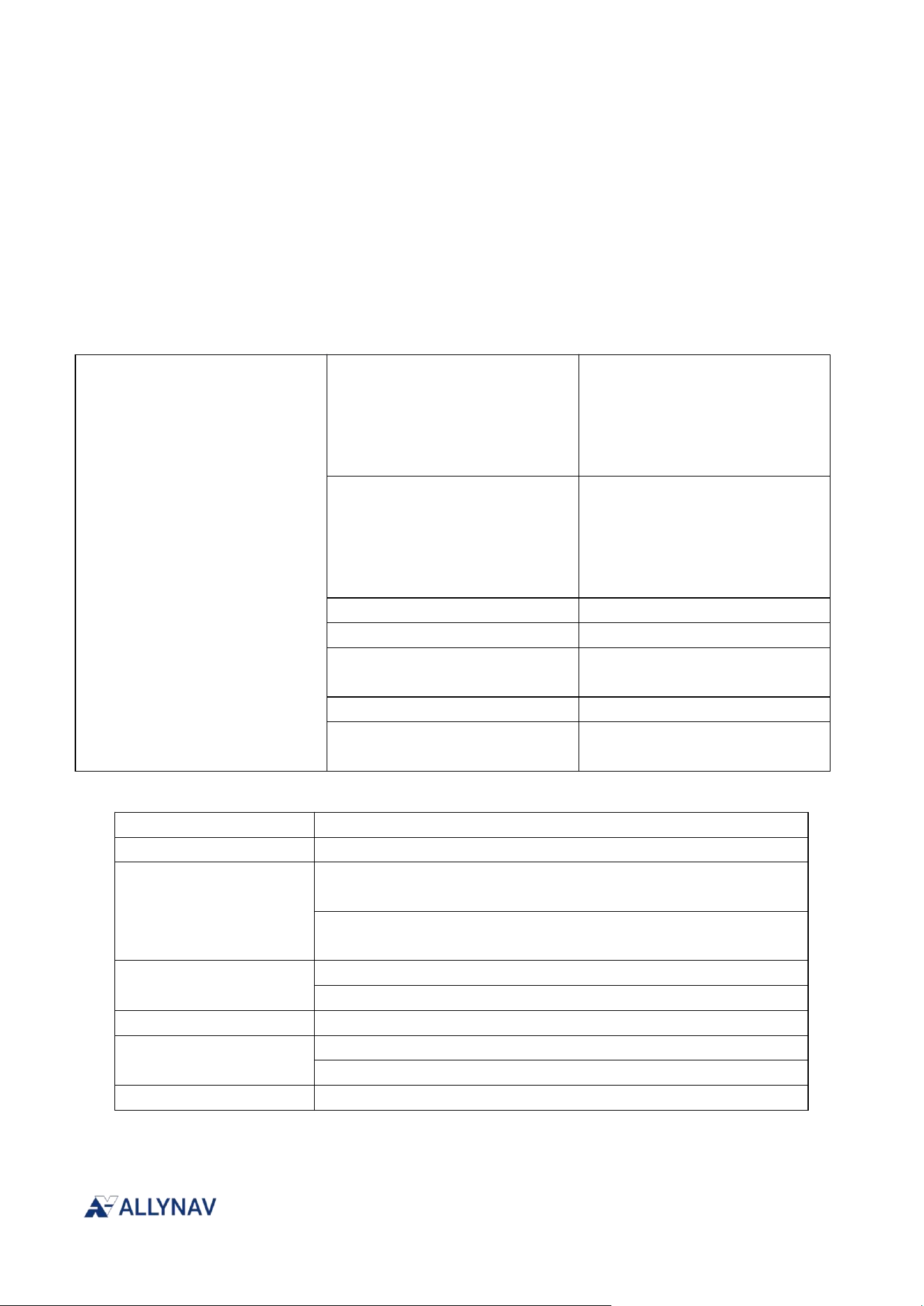
R100 Receiver Installation and Operation User Manual V1
considering possible antenna phase center offset errors.
4. Open sky and undisturbed environment
5. Open sky, unobstructed view, 99% static
6. -130dBm @More than 12 available satellites
7. Laboratory Ideal Environment Test Results
IMU performance parameters
Performance indicators
Attitude accuracy
Roll/Pitch :<0.2° rms
Heading:<0.3° rms
(Vehicle speed greater than
1km/h, Ackermann steering
structure in-vehicle scenario)
Location estimation accuracy
<2% @1σ
(Vehicle-mounted scenario,
satellite loss for 30 seconds, no
wheel speedometer
combination)
Update rate
100Hz
Gyroscope range
±500°/s
Gyroscope zero-bias instability
XY:4°/h Z:3°/h
@25℃,ALLAN variance,1σ
Accelerometer range
±6g
Accelerometer zero bias
instability
XY:20μg Z:40 μg
@25℃,ALLAN variance,1σ
Radio performance parameters
Frequency range
410-470MHz
Work mode
Single Receiver
Communication Protocol
GFSK model:
TRIMTALK、TRANSEOT、TRIMMARK3
LORA model:
LIANSHI、CSST Transmission Protocol
Channel spacing
GFSK model:12.5KHZ、25KHZ
LORA model:250KHz
Modulation method
CSS/GFSK/4FSK
air speed
GFSK model 9600bps、19200bps
LORA model 18000bps 、 15000bps 、 12000bps、 11000bps
Serial port speed
115200bps 、 38400bps 、 19200bps、9600bps
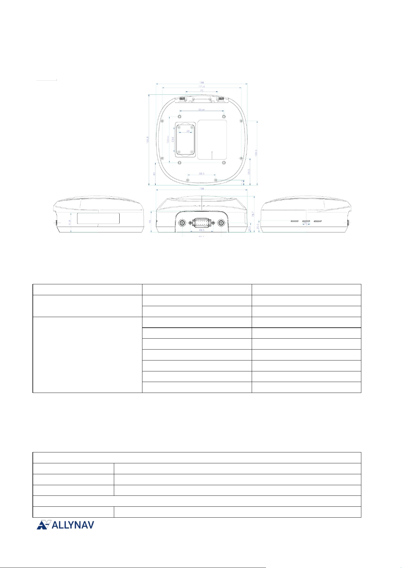
R100 Receiver Installation and Operation User Manual V1
A.2 R100 Mechanical Specifications
Wireframe diagram (unit: millimeters)
A.3 R100 Environmental and Electrical Specifications
Operating temperature and protection level
User Interaction
indicator lights
POW、SA、LINK
Electrical performance
powered by
9-36V DC
Power consumption
≤4.0W
physical properties
size
198mm×196.8mm×78.7mm
weight
<0.88Kg(No support)
Material
PC-PBT/ silicone
Operating temperature
-20℃~+75℃
Storage temperature
-40℃~+85℃
Protection level
IP67
Impact and vibration
A 1m drop, marble
A.4 R100 Data Communication Specification
CONFIG-RS232
baud rate
115200
Support signal
Sending and receiving
R100 port
12-core Dechi head
COM-RS232
baud rate
9600, 19200, 38400, 57600, 115200(default), 230400, 460800, 921600
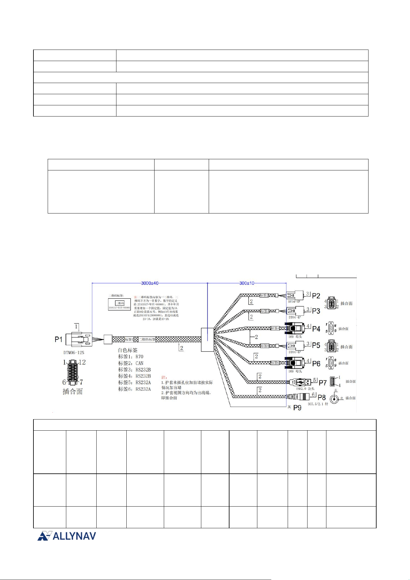
R100 Receiver Installation and Operation User Manual V1
Support signal
Sending and receiving
R100 port
12-core Dechi head
CAN
Default baud rate
500K
Supported baud rates
250K、500K
R100 port
12-core Dechi head
A.5 R100 Speed
Pulse Specification
Signal
Input/Output
illustrate
velocity pulse signal
Output
SET PWMFREQ mode,freq
The speed specified in the GPRMC statement is
converted into a PWM frequency with a 50%
duty cycle according to a specific ratio.
A.6 R100 Antenna Interface Cable (Optional Accessory)
Debugging wire harness
Wiring diagram
P1
P2
CAN
P3
CONFIG
-RS232
P4
CONFIG
-RS232
P5
COM
-RS23
2
P6
COM
-RS23
2
P7
USB
P8
DC
P9
PL
S
Core
specification
s
POW
5 red
1 red
cor
e /
red
0.5mm
2
GND
7 black
3 black
3 black
5 black
3
black
5
black
4 black
she
ll /
0.5mm
2
R100 Receiver Installation and Operation User Manual V1
bla
ck
CANL
9 Light
blue
4 Light
blue
0.5mm
2
Twisted Pair
CANH
10
orang
e
2
orang
e
232BRX
11
Brown
4 Brown
3 Brown
0.5mm
2
232BTX
12
yellow
2 yellow
2 yellow
0.5mm
2
232ATX
1 blue
2 blue
2 blue
0.5mm
2
232AR
X
2 pink
4 pink
3 pink
0.5mm
2
USBD+
3
green
3
green
0.35mm
2
Twisted Pair
USBD-
4
white
2
white
PLS
6 Ash
As
h
0.5mm
2
A.7 R100 Custom Cable Recommendation
Connection harnesses can be customized to meet specific needs; please contact ALLYNAV's
sales manager for consultation.
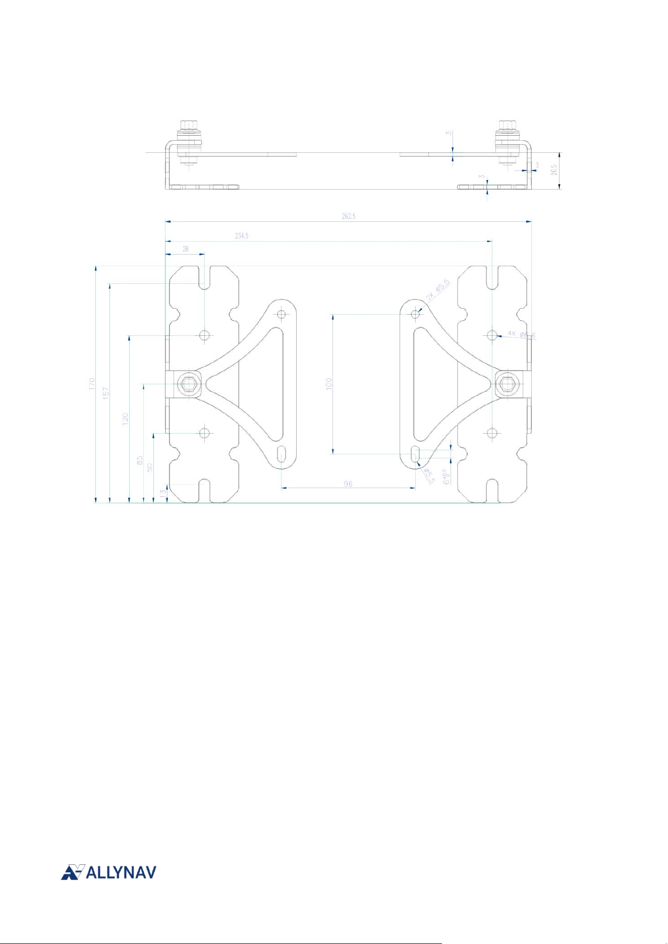
R100 Receiver Installation and Operation User Manual V1
A.8 R100 Mounting Plate Specifications

R100 Receiver Installation and Operation User Manual V1
This device complies with part 15 of the FCC Rules. Operation is subject to the following two conditions:
(1) This device may not cause harmful interference, and (2) this device must accept any interference
received, including interference that may cause undesired operation.
Any Changes or modifications not expressly approved by the party responsible for compliance could
void the user's authority to operate the equipment.
Note: This equipment has been tested and found to comply with the limits for a Class B digital device,
pursuant to part 15 of the FCC Rules. These limits are designed to provide reasonable protection
against harmful interference in a residential installation. This equipment generates uses and can radiate
radio frequency energy and, if not installed and used in accordance with the instructions, may cause
harmful interference to radio communications. However, there is no guarantee that interference will not
occur in a particular installation. If this equipment does cause harmful interference to radio or television
reception, which can be determined by turning the equipment off and on, the user is encouraged to try to
correct the interference by one or more of the following measures:
-Reorient or relocate the receiving antenna.
-Increase the separation between the equipment and receiver.
-Connect the equipment into an outlet on a circuit different from that to which the receiver is connected.
-Consult the dealer or an experienced radio/TV technician for help.
This equipment complies with FCC radiation exposure limits set forth for an uncontrolled environment.
This equipment should be installed and operated with minimum distance 20cm between the radiator &
your body