Sliding Gate Opener
User Manual
Read Carefully Before Use
Keep for Future Reference
V20231201
SGO-0000-01 1400 lb. Complete Kit
SGO-EC06-02 1400 lb. Essentials Kit
SGO-1801-GY 1800 lb. Home Use Kit


PLEASE READ THIS FIRST
Thank you for purchasing our sliding gate opener.
This manual only applies to the following CO-Z
®
products.
This manual provides the knowledge needed to safely and eciently operate this product and
manufacturer-licensed accessories. Contact customer service if you have any questions.
Read this manual carefully before installation and use. Follow this manual completely, paying
particular attention to safety instructions. Failure to do so may cause serious personal injury and
product damage.
This product was exclusively designed and manufactured for the use specied in this manual.
Any use not specified herein could potentially damage the product and pose risks. Incorrect
installation or improper use of the product may result in harm to individuals, animals, or property.
This manual describes the congurations, options, and accessories of this product.
This manual contains crucial specifications, precautions, and troubleshooting information
necessary to ensure safe and eective use of this product. Keep this manual in an easily
accessible location and store it securely.
Name Model
Sliding Gate Opener 1400 lb.
Sliding Gate Opener 1400 lb. Essentials Kit
Sliding Gate Opener 1800 lb. Home Use Kit
SGO-0000-01
SGO-EC06-02
SGO-1801-GY
Audience
This manual is intended for adult readers who are capable of independent behavior and
autonomy and who possess a basic awareness of mechanical and electrical safety precautions.
Users must be fully aware of the mechanical and electrical risks that may be involved in the
installation and use of such products before use.
Symbol Guide
The following symbols are used in this manual:
Symbol Meaning
Warning
Precautions to prevent serious property damage or personal injury
Caution
Precautions to prevent damage to equipment and facilities
Note
Crucial information that can contribute to safer and more ecient usage

FOR YOUR RECORDS
You can record the following information for future reference in case you require service
for your automatic gate opener.
Model:
Date of Purchase:
Place of Purchase:

Contents
1. General Safety Information..................................................................................................1
2. Product Description .............................................................................................................2
2.1 Specications ...................................................................................................................2
SGO-0000-01 ...............................................................................................................................................3
SGO-EC06-02 ..............................................................................................................................................5
SGO-1801-GY ..............................................................................................................................................7
2.2 Package List .....................................................................................................................9
Main Components ........................................................................................................................................9
Base Components ........................................................................................................................................9
Chain Support Components .......................................................................................................................10
Magnetic Limit Switch Components ........................................................................................................... 11
Infrared Sensor (SGO-1801-GY Only) ....................................................................................................... 11
Optional Accessories for Function Expansion ............................................................................................12
3. Preparation..........................................................................................................................13
3.1 Denition of Sliding Direction..........................................................................................13
3.2 Check Installation Conditions .........................................................................................14
3.3 Customize Your Installation ............................................................................................14
3.4 Prepare Components and Tools .....................................................................................15
4. Install Safety Guards .......................................................................................................... 16
5. Mechanical Installation ......................................................................................................17
5.1 Safety Precautions .........................................................................................................17
5.2 Base Component Assembly ...........................................................................................18
5.3 Base-Main Unit Connection ............................................................................................ 18
5.4 Chain Installation ............................................................................................................19
5.5 Chain Test .......................................................................................................................24
5.6 Chain Box Cover Reinstallation ...................................................................................... 24
6. Electrical Component Installation.....................................................................................25
6.1 Important Information ....................................................................................................25
6.2 Circuit Connection Methods ...........................................................................................25
6.3 Control Board Description ..............................................................................................26
Overview.....................................................................................................................................................26
Indicator Lights ...........................................................................................................................................27
Control Buttons ........................................................................................................................................... 28
Digital Display ............................................................................................................................................. 28
Interfaces .................................................................................................................................................... 29

6.4 System Powering............................................................................................................30
6.5 Direction Reversal ..........................................................................................................30
6.6 Limit Switch Magnets......................................................................................................31
6.7 Fixation ...........................................................................................................................32
6.8 Infrared Equipment Connection (SGO-1801-GY Only) ..................................................34
6.9 Wire Connection Guidance of Optional Accessories ......................................................35
Warning Light .............................................................................................................................................35
Push Button ................................................................................................................................................35
Swipe Card, Digital Keypad, and Other External Devices ..........................................................................35
Loop Detector .............................................................................................................................................36
7. Operation.............................................................................................................................37
7.1 Remote Control Description ...........................................................................................37
7.2 Functions ........................................................................................................................37
Movement Limitation ..................................................................................................................................37
Mechanical Obstruction Feedback .............................................................................................................37
Infrared Obstruction Feedback ...................................................................................................................38
Automatic Closing ....................................................................................................................................... 38
Pedestrian Mode ........................................................................................................................................38
Vehicle Detection ........................................................................................................................................ 38
Travel Learning ........................................................................................................................................... 38
Motor Running Protection ........................................................................................................................... 39
Manual Mode .............................................................................................................................................. 39
7.3 Code Display ..................................................................................................................39
7.4 Basic Function Conguration..........................................................................................40
Accessing the Setting Menus .....................................................................................................................40
Selecting Menus and Adjusting Values .......................................................................................................40
Conrming Selections and Saving Changes ..............................................................................................40
Exiting the Setting Menus ........................................................................................................................... 40
7.5 Advanced Function Conguration...................................................................................40
Learning Codes (Remote Control Learning)...............................................................................................40
Clearing Codes ........................................................................................................................................... 40
Travel Learning ........................................................................................................................................... 41
Parameter Adjustment ................................................................................................................................ 41
8. Troubleshooting .................................................................................................................43
9. Maintenance ........................................................................................................................ 46
10. Disposal.............................................................................................................................48
11. Contact Information ..........................................................................................................48
1
1. General Safety Information
Read the following information carefully before installation and use. This section provides general
safety precautions. For particular precautions, consult the dedicated operation instructions related
to those tasks.
Caution
• Any actions or elements not explicitly covered in these instructions are strictly prohibited.
• ALWAYS keep bystanders, pets, and any objects away from the automation operation
area.
• NEVER cross the path of the gate while it is in motion. Even driving through when it is
closing remains EXTREMELY dangerous.
• NEVER let children operate or play with the gate controls and keep control devices out of
the reach of children to prevent unintentional automation activation.
• DO NOT initiate the gate opener unless you have a clear line of sight and can conrm that
its pathway is clear of people, pets, or other obstructions. Maintain constant vigilance over
the gate's entire range of motion.
• NEVER modify the automation components without explicit authorization from the
factory. NEVER attempt to perform repairs on the automotion system. NEVER replace
any components with nonidentical ones. Making modications or adding components by
personnel without proper training or involving unauthorized parts will void the manufacturer's
warranty. Seek professional assistance from qualied technicians if needed.
• Maintain the gate opener as instructed herein. ALWAYS unplug the gate opener before
performing any inspection, servicing, or maintenance.
• Dispose of the packing materials (incl. plastic, cardboard, polystyrene, etc.) in accordacne
with local and national laws and regulations.
• Keep nylon or polystyrene bags out of the reach of children.
Warning
General Safety Information

2
Product Description
2. Product Description
Designed for installation on a slide-to-open single leaf gate, this opener system autonomously
manages gate control for seamless vehicle entry and exit from your property. This operator
accommodates a range of accessories, which are outlined in Optional Accessories below.
Equipped with a safety feature, this operator halts and reverses gate movement upon encountering
an obstruction. Additionally, an adjustable auto-close feature is included. The system boasts
eortless installation and setup, requiring minimal maintenance to ensure optimal performance.
Warning
This product is not intended for the containment of animals.
2.1 Specications
This manual covers the following three models of sliding gate openers. For accurate information,
read the content corresponding to the model you have purchased.

3
Product Description
Main Unit
Input Voltage & Freq.
110 V AC 60 Hz
Components
Motor Type
Alternating Current (AC)
Motor Coil Material
Copper
Brushed/Brushless Motor
Single-Phase Induction Motor
Rated Voltage
110 V AC
Rated Current
2.5 A
Rated Power
220 W
Torque
22 N·m
Motor Speed
1500 rpm
Gear Speed
62 rpm
Housing Material
Acrylonitrile Butadiene Styrene (ABS)
Motor Base Material
Cast Aluminum
Duty Cycle
S2, 20 min.
Noise Level
< 56 dB
Gear Shaft
Gear Material
Steel
Turbine Material
Copper
Worm Material
Steel
Gate Compatibility
Max. Width
40 ft. (12.2 m)
Max. Weight
1400 lb. (635 kg)
Sliding Speed
3.3 fpm (13 m/min.)
Operational Environment
Ambient Temperature
−4 to 158°F (−20 to 70°C)
Weatherproof Rating
IP44
Remote Control
System Capacity
120 Remotes
Frequency
433.92 MHz (Rolling Code)
Eective Range
54.7 yd. (50 m)
Gate Control Modes
Remote, Manual
SGO-0000-01

4
Product Description
Functions
Motor
Thermal Cuto
Yes
Gate Operation
Operating Time
60 sec.
Sliding Speed
Yes
Slow Start Time
No
Slow Stop Time
Yes
Obstacle Stop/Reversal
Opening: Obstacle Stop / Closing: Obstacle Reversal
Auto-Close Timer Range
0–99 sec.
Sliding Direction
Yes
Pedestrian Mode
Yes
Limit Switch Type
Magnetic Steel
Notication
Opening/Closing
Digital Display Notication
Obstacle Reversal
Limit Return
Remote Control
Button Conguration
Single-Button/Three-Button Control
Size and Weight
Product Dimensions
14.2×11.2×18.7 in. (36×28×55.5 cm)
Product Net Weight
(Including Accessories)
15.2 kg
Accessories
Control Box Type
Built-in
Remote Control Quantity
2
Manual Key Quantity
2
Fuse Type
10 A
Chain Length
9.8 in. (3 m) ×2
Installation Accessories
Yes
Installation Accessory Material
Silver-Plated Zinc Steel
SGO-0000-01

5
Product Description
Input Voltage & Freq.
110 V AC 60 Hz
Components
Motor Type
Alternating Current (AC)
Motor Coil Material
Aluminum
Brushed/Brushless Motor
N/A
Rated Voltage
110 V AC
Rated Current
2 A
Rated Power
270 W
Torque
14 N·m
Motor Speed
1400 rpm
Gear Speed
54 rpm
Housing Material
Acrylonitrile Butadiene Styrene (ABS)
Motor Base Material
Cast Aluminum
Duty Cycle
S2, 20 min.
Noise Level
< 56 dB
Gear Shaft
Gear Material
Steel
Turbine Material
Nylon
Worm Material
Steel
Gate Compatibility
Max. Width
40 ft. (12.2 m)
Max. Weight
1400 lb. (635 kg)
Sliding Speed
3.3 fpm (13 m/min.)
Operational Environment
Ambient Temperature
−4 to 158°F (−20 to 70°C)
Weatherproof Rating
IP44
Remote Control
System Capacity
120 Remotes
Frequency
433.92 MHz (Rolling Code)
Eective Range
32.8 yd. (30 m)
Gate Control Modes
Remote, Manual
Main Unit
SGO-EC06-02

6
Product Description
Functions
SGO-EC06-02
Motor
Thermal Cuto
Yes
Gate Operation
Operating Time
60 sec.
Sliding Speed
Yes
Slow Start Time
No
Slow Stop Time
Yes
Obstacle Stop/Reversal
Opening: Obstacle Stop / Closing: Obstacle Reversal
Auto-Close Timer Range
0–99 sec.
Sliding Direction
Yes
Pedestrian Mode
Yes
Limit Switch Type
Magnetic Steel
Notication
Opening/Closing
Digital Display Notication
Obstacle Reversal
Limit Return
Remote Control
Button Conguration
N/A
Size and Weight
Product Dimensions
14.2×11.2×18.7 in. (36×28.5×47.5 cm)
Product Net Weight
(Including Accessories)
15.2 kg
Accessories
Control Box Type
Built-in
Remote Control Quantity
2
Manual Key Quantity
2
Fuse Type
10 A
Chain Length
9.8 in. (3 m) ×2
Installation Accessories
Yes
Installation Accessory Material
Silver-Plated Zinc Steel

7
Product Description
Main Unit
Input Voltage & Freq.
110 V AC 60 Hz
Components
Motor Type
Alternating Current (AC)
Motor Coil Material
Copper
Brushed/Brushless Motor
Single-Phase Induction Motor
Rated Voltage
110 V AC
Rated Current
2.8 A
Rated Power
180 W
Torque
26 N·m
Motor Speed
1500 rpm
Gear Speed
62 rpm
Housing Material
Acrylonitrile Butadiene Styrene (ABS)
Motor Base Material
Cast Aluminum
Duty Cycle
S2, 20 min.
Noise Level
< 56 dB
Gear Shaft
Gear Material
Steel
Turbine Material
Copper
Worm Material
Steel
Gate Compatibility
Max. Width
40 ft. (12.2 m)
Max. Weight
1800 lb. (816.5 kg)
Sliding Speed
3.3 fpm (13 m/min.)
Operational Environment
Ambient Temperature
−4 to 158°F (−20 to 70°C)
Weatherproof Rating
IP44
Remote Control
System Capacity
120 Remotes
Frequency
433.92 MHz (Rolling Code)
Eective Range
54.7 yd. (50 m)
Gate Control Modes
Remote, Manual
SGO-1801-GY
8
Product Description
Functions
SGO-1801-GY
Motor
Thermal Cuto
Yes
Gate Operation
Operating Time
60 sec.
Sliding Speed
Yes
Slow Start Time
No
Slow Stop Time
Yes
Obstacle Stop/Reversal
Opening: Obstacle Stop / Closing: Obstacle Reversal
Auto-Close Timer Range
0–99 sec.
Sliding Direction
Yes
Pedestrian Mode
Yes
Limit Switch Type
Magnetic Steel
Notication
Opening/Closing
Digital Display Notication
Obstacle Reversal
Limit Return
Remote Control
Button Conguration
Single-Button/Three-Button Control
Size and Weight
Product Dimensions
14.2×11.2×18.7 in. (36×28.5×47.5 cm)
Product Net Weight
(Including Accessories/Infrared Sensor)
15.25 kg
Accessories
Control Box Type
Built-in
Remote Control Quantity
2
Manual Key Quantity
2
Fuse Type
10 A
Chain Length
9.8 in. (3 m) ×2
Installation Accessories
Yes
Installation Accessory Material
Silver-Plated Zinc Steel
Wired Infrared Sensors
1 Pair (2 Units)
9
Product Description
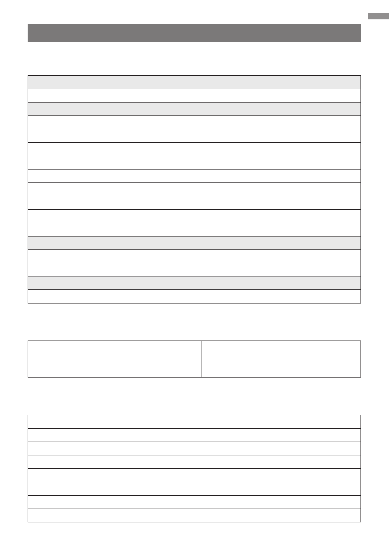
2.2 Package List
Item Name Qty. Image
1 Main Unit 1
2 Chain Box Cover 1
3 Chains 2
4 Manual Keys 2
Main Components
Item Name Qty. Image
1 Base Frame 4-in-1
2 M6×20 Hex Bolts 4
3 M6 Hex Nuts 4
4 M6 Spring Washers 4
Base Components
10
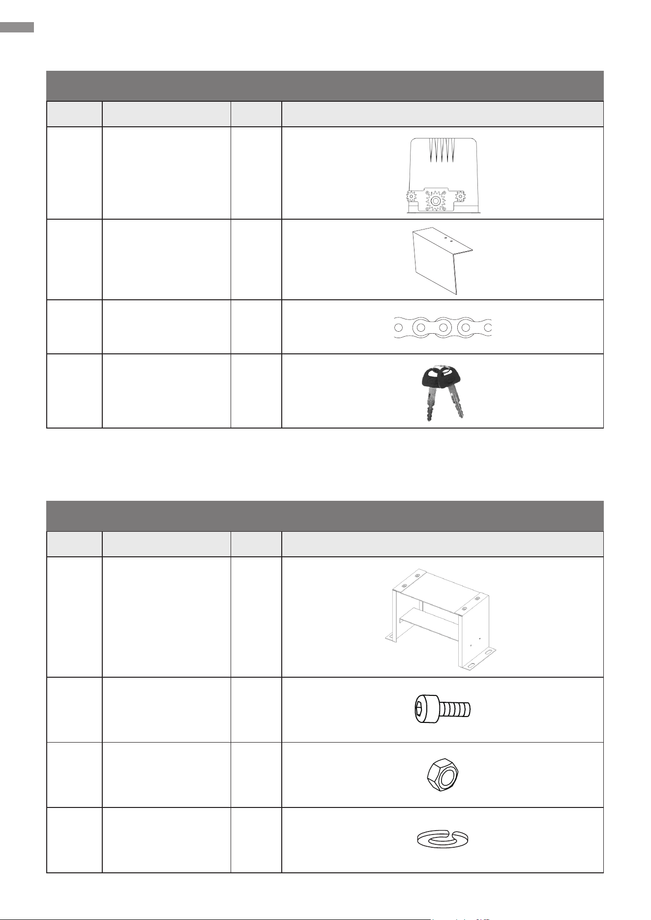
Product Description
Item Name Qty. Image
5 M6 Flat Washers 4
6 M10×45 Hex Bolts 4
7 M10 Flat Washers 4
8
M10 Spring
Washers
4
9
M10×80 Anchor
Bolts
4
Base Components (Continued)
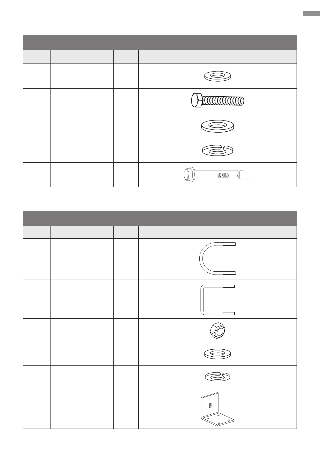
Item Name Qty. Image
1 Arched U-Bolts 4
2 Square U-Bolts 4
3 M6 Hex Nuts 8
4 M6 Flat Washers 8
5 M6 Spring Washers 8
6 Chain Brackets 2
Chain Support Components
11
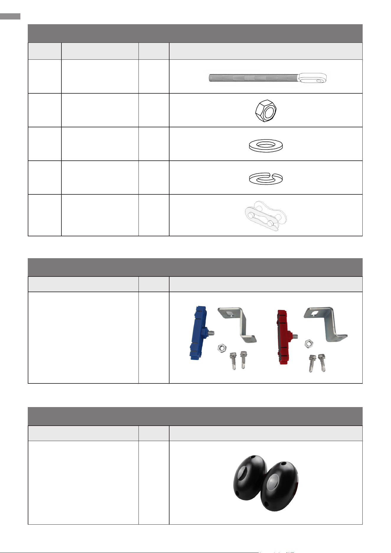
Product Description
Item Name Qty. Image
7 M8 Bolts 2
8 M8 Hex Nuts 4
9 M8 Flat Washers 4
10 M8 Spring Washers 4
11 Chain Joints 2
Chain Support Components (Continued)
Name Qty. Image
Limit Switches
(Incl. one M8 Nuts &
two ST6×25 Screws)
2
Name Qty. Image
Infrared Sensor Set
(Incl. Installation Accessories)
1
Magnetic Limit Switch Components
Infrared Sensor (SGO-1801-GY Only)

12
Product Description
Optional Accessories for Function Expansion
• Warning Lights (Powered by AC)
• Push Button
• Swipe Card
• Digital Keypad
• Loop Detector (Ground Sensor)
Warning
Using components from other suppliers
will void the manufacturer’s responsibility
in regard to the automation safety and
proper operation.
13
Preparation
3. Preparation
This chapter describes the preparation work that needs to be done before installation. Please
carefully read and follow the instructions. Failure to do so may cause unsuccessful installation,
shorten the lifespan of your gate, or even result in personal injury and property damage.
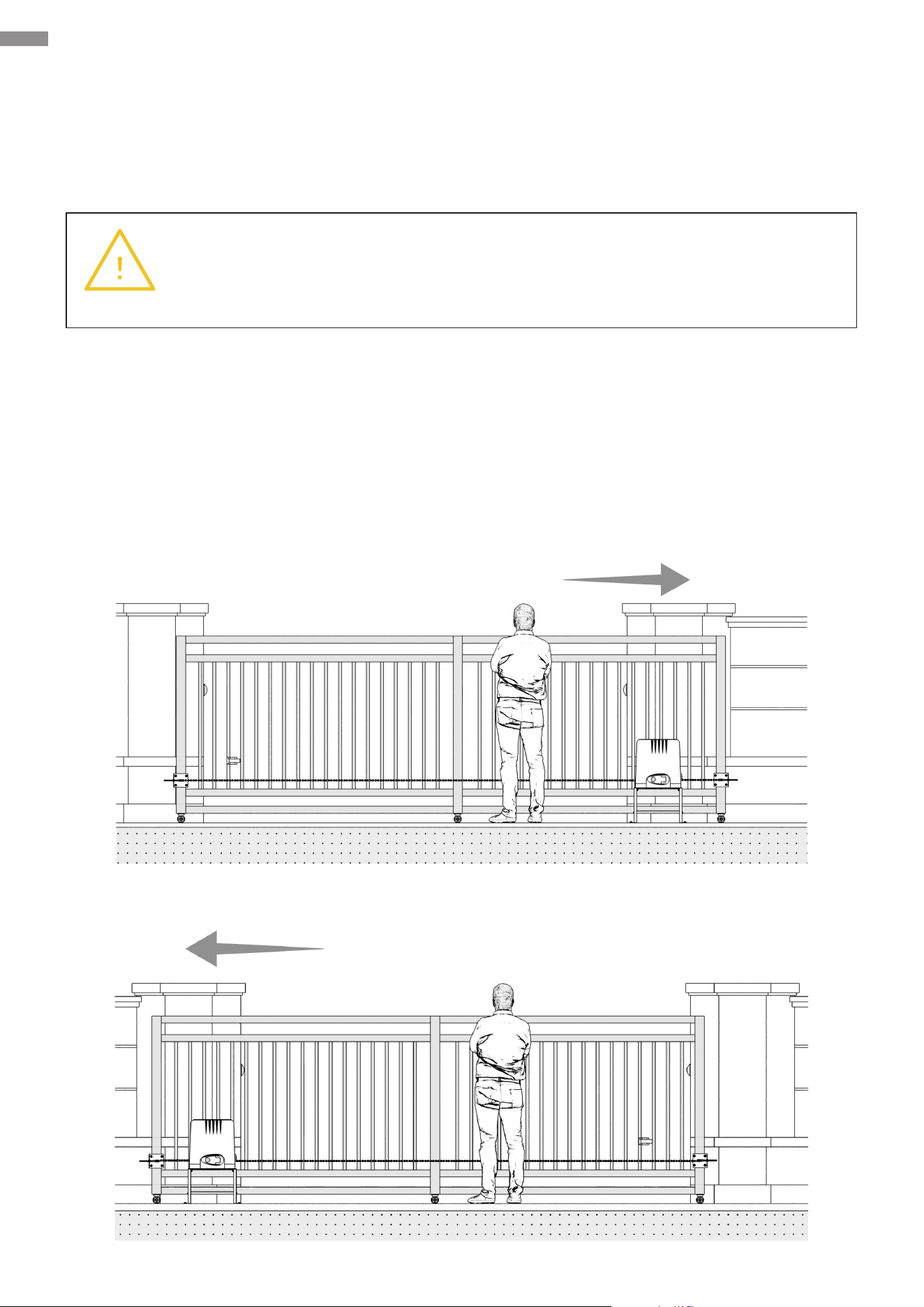
3.1 Denition of Sliding Direction
Sliding direction herein refers to the direction in which your gate slides when you are facing the
gate and standing at the side of your gate opener. This device is designated for immediate use with
gates that slide open to the right. The installation procedures for gates that slide open to the left are
basically the same as that for gates that slide open to the right, except for installation procedure
with respect to the electrical part. Refer to Chapter 6 for details.
Right-Slide Opening
Left-Slide Opening
Warning
NEVER install this product in an explosive atmosphere.
14
Preparation
3.2 Check Installation Conditions
Before you start to install the gate opener, check to ensure that the installation conditions are
appropriate.
• Ensure your gate fullls Gate Compatibility in Specications above.
• Ensure your gate’s pillars are rmly secured to the ground with concrete, contributing to stability
and reliability when in use.
• Ensure your gate was installed correctly and slides smoothly, without visible friction with its
track or any risk of derailment throughout its movement.
• Ensure the bottom of your gate remains horizontal and its sides stay vertical during movement.
• Ensure sucient space between your gate and its surrounding structures, posing no crushing
or jamming risk during movement.
• Ensure no obstructions within the range of your gate’s movement.
• Ensure proper protection against any exposed pinch points or prevent any pinch points from
being exposed.
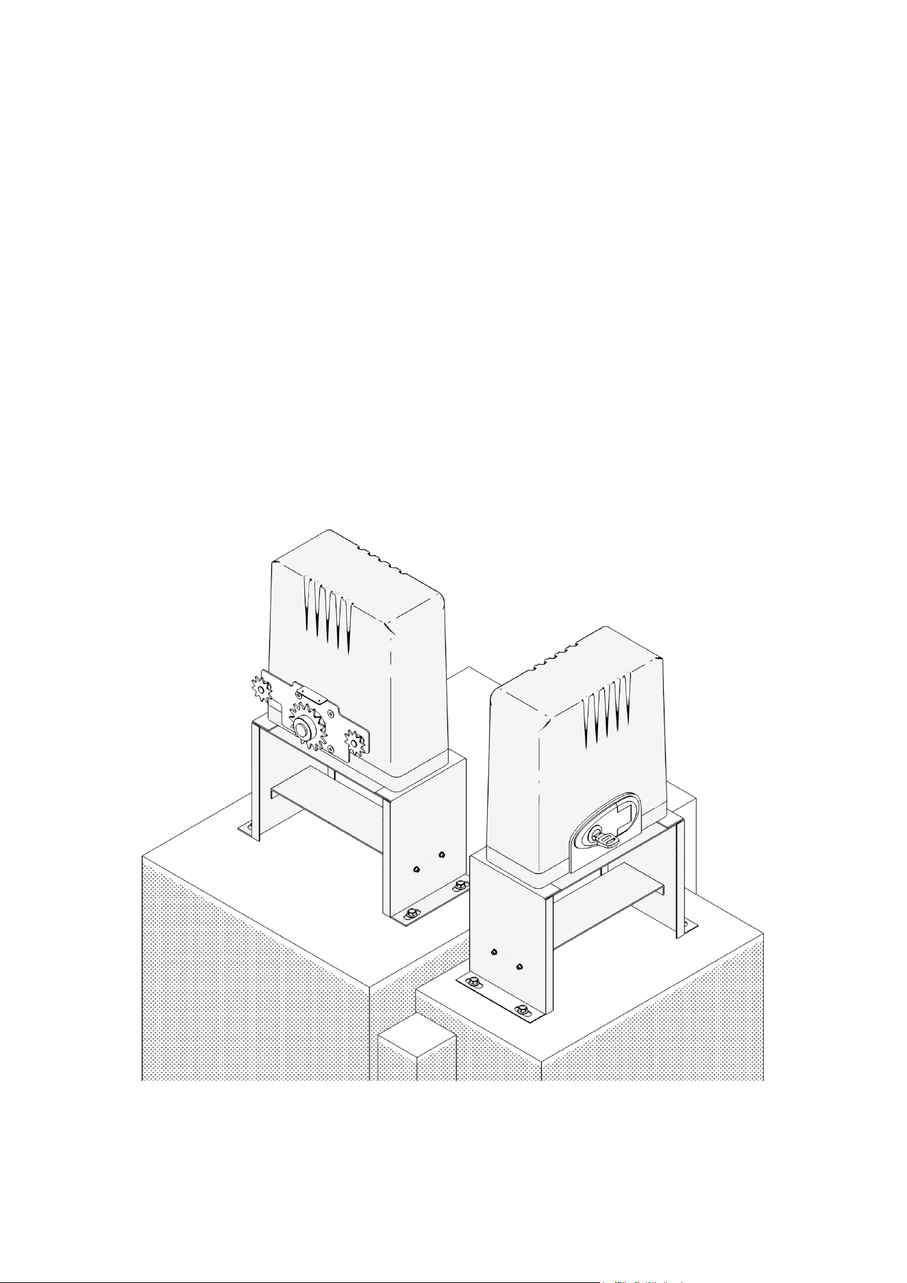
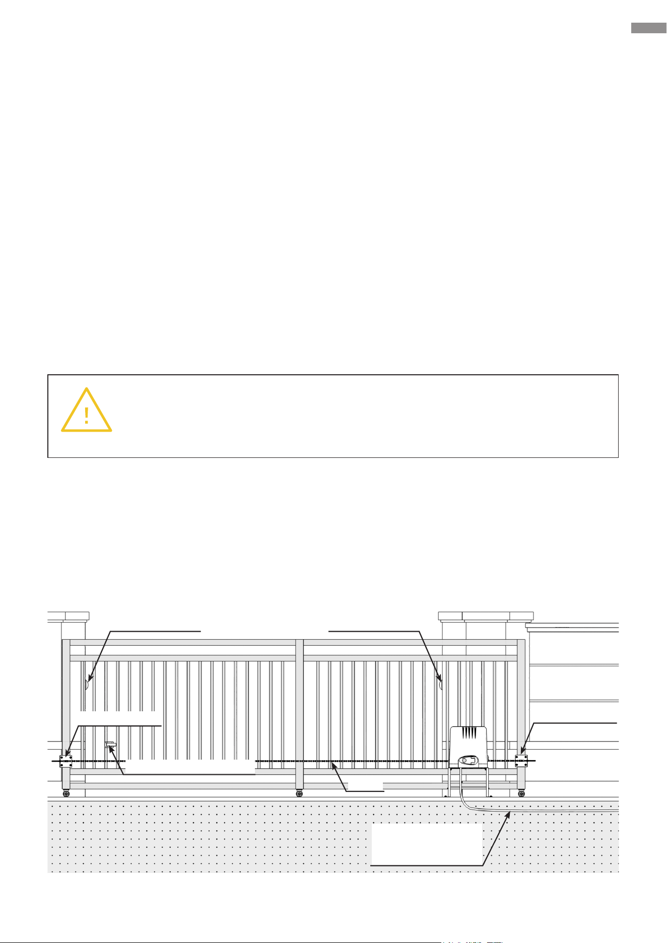
3.3 Customize Your Installation
Refer to the diagram below, which illustrates the result of the correct installation.
Warning
Using with improperly installed or unqualied gates, as well as any deformation on
your gates occurring during use, will void the manufacturer’s responsibility.
Chain
Magnetic Limit Switch
Use PVC Conduit
(not included)
for power cables
Chain Bracket
Chain Bracket
Infrared Sensor Infrared Sensor

15
Preparation
The opener should:
• only be installed on the inside of your gate.
• not interfere with your vehicle access.
• be installed where it will not collide with the gate frame during movement, leaving at least 11.8
inches (30 cm) from any part.
The power line should be covered by PVC conduits (not included), and the external wiring should
be buried underground to ensure safe use. Prepare a working power source nearby and arrange
appropriate wiring routing. Select accessories necessary for your work.
3.4 Prepare Components and Tools
Check that all necessary accessories are intact and complete, preparing other helpful items as
needed.
Components Not Included but Necessary
• Double-Core Cable: 18 AWG (0.75 mm2), usu. 6.6 feet (2 m) long
• Conduits
• 3-Prong U.S. Plug
• Infrared Sensor Connection Cables: Single or double-core, usually 1.6 feet (0.5 m) long
Tools Needed for Installation
• Spirit Level
• Adjustable Wrench
• Socket or Sleeve Kit
• Flathead Screwdriver
• Phillips Screwdriver
• Tape Measure
• Marker/Pencil
• Chainsaw/Hacksaw
• Hammer Drill
• Wire Cutters
• Wire Strippers

16
4. Install Safety Guards
For your safety, adapt following safety protection measures:
• Post at least two warning signs at prominent positions on both sides of your gate.
• Controls intended for user activation MUST be located at least 10 feet (3 m) away from any
moving part of your gate and where the user is prevented from reaching over, under, around,
or through the gate to operate the controls. Outdoor or easily accessible controls shall have a
security feature to prevent unauthorized use.
• Exercise care to reduce the risk of nuisance tripping, such as when a vehicle trips the sensors
while your gate is still moving in its opening direction.
Install Safety Guards
17
Mechanical Installation
5. Mechanical Installation
5.1 Safety Precautions
Warning
Put on appropriate personal protective equipment such as work gloves and be sure
your gate is completely closed.
Warning
Be careful with any moving parts and avoid close proximity to areas where ngers
or hands could be pinched.
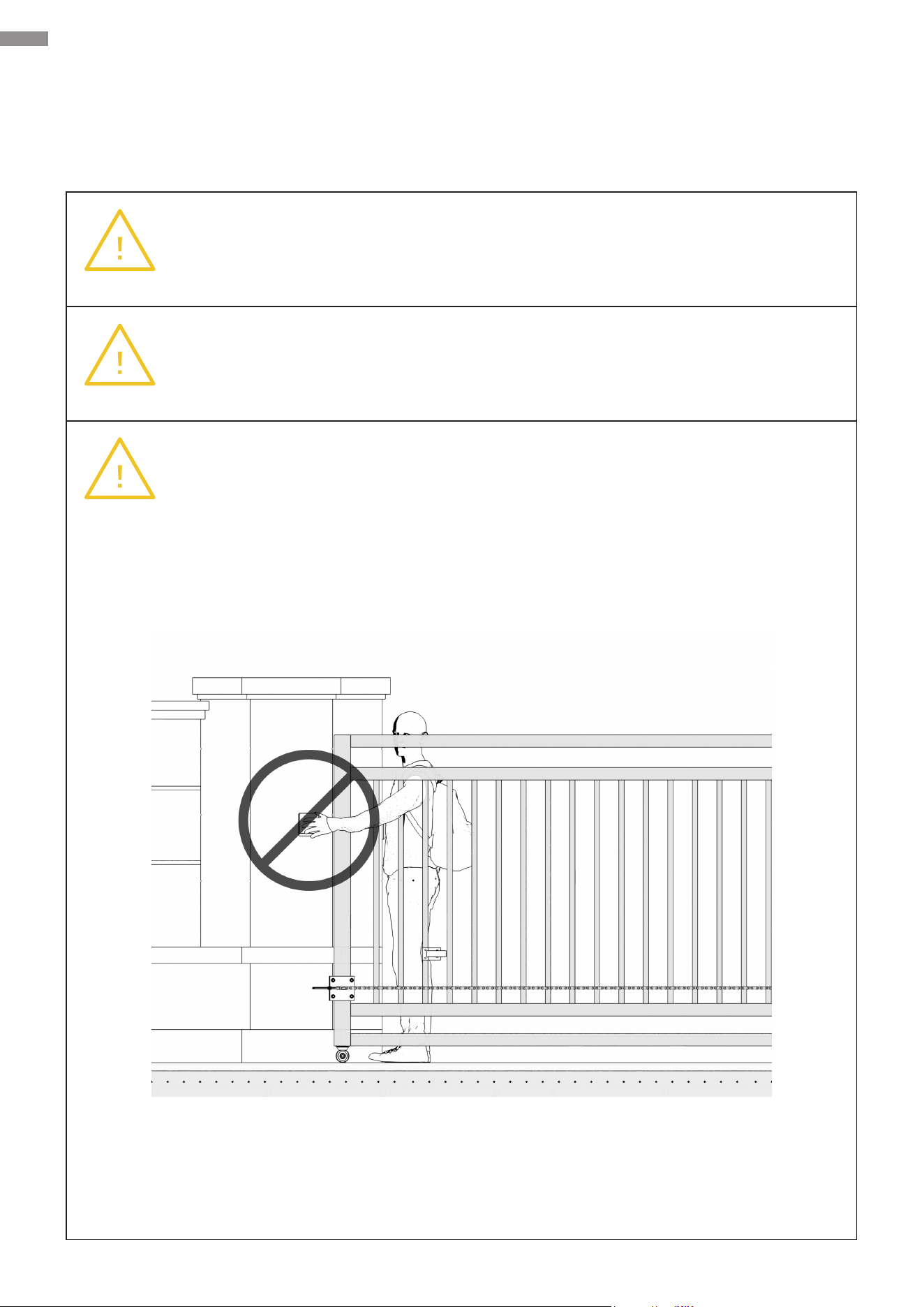
Warning
NEVER install any control device where a user will be tempted to reach through the
gate to operate the gate opener.
18
Mechanical Installation
5.2 Base Component Assembly
Connect these base components as shown.
Parts to be used:
• M6×20 Hex Bolts (×4)
• M6 Spring Washers (×4)
• M6 Flat Washers (×4)
• M6 Hex Nuts (×4)
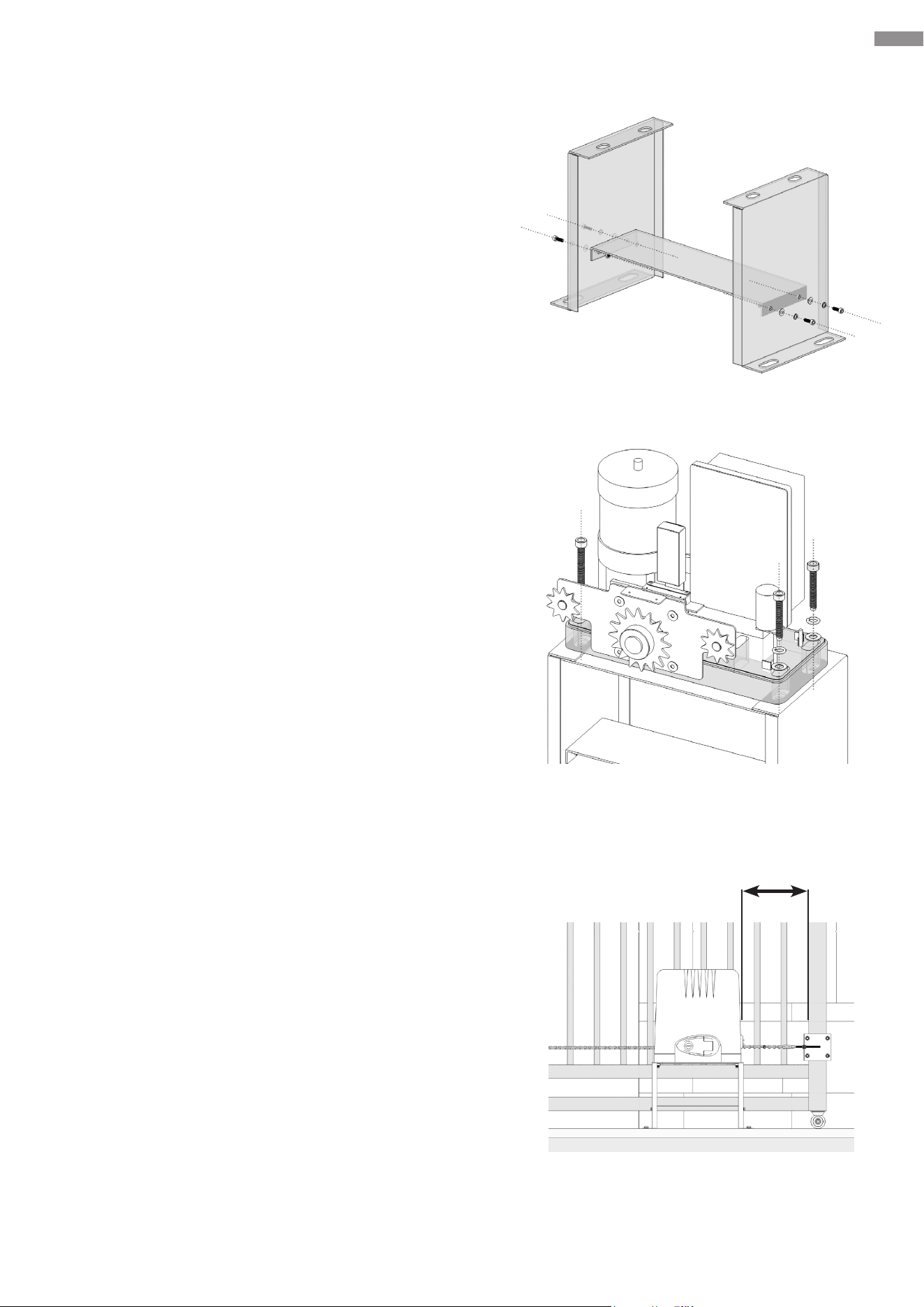
5.3 Base-Main Unit Connection
1. Remove the protective cover from the main unit and
place it nearby. Attach this unit to its base using the
following fasteners, being careful not to overtighten
them.
Parts to be used:
• M10×45 Hex Bolts (×4)
• M10 Spring Washers (×4)
• M10 Flat Washers (×4)
2. Select an appropriation position for the main unit and
place it.
• Ensure the distance between the chain box and
your gate is no larger than 10 inches (25 cm) while
allowing enough space to prevent scratches and
collisions during operation.
• Ensure a minimum distance of 7.9 inches (20 cm)
between this unit and the nearest gate frame (with
the gate fully closed)
• Ensure this unit is parallel to the gate.
• It is advisable not to permanently x this unit for
now, in case it needs to be relocated during the
ongoing installation.
10 inches
25 cm
19
Mechanical Installation
5.4 Chain Installation
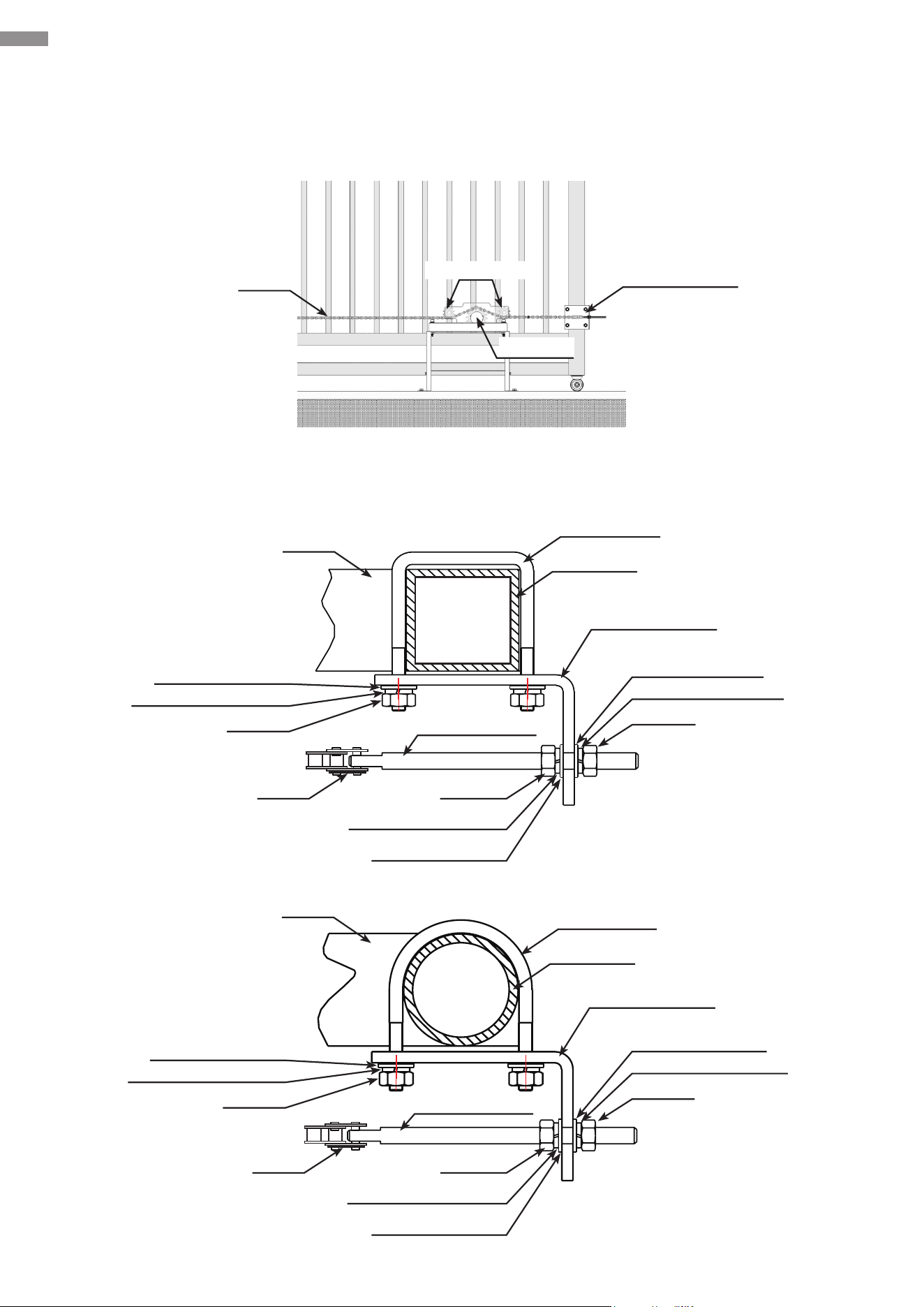
Below is a diagram of chain installation.
Schematic diagrams of chain bracket assemblies installed on square gate frame and round gate
frame are shown below.
Chain
Gate
Gate
M8 Chain Bolt
M8 Chain Bolt
Sprocket
Idler Wheels
Chain Bracket
Square Bolt
Square Bolt
Gate Post
Chain Bracket
Chain Bracket
Gate Post
M8 Nut
M8 Nut
M6 Nut
M8 Spring Washer
M8 Spring Washer
M6 Spring Washer
M8 Flat Washer
M8 Flat Washer
M6 Flat Washer
Chain
M8 Nut
M8 Nut
Chain
M8 Spring Washer
M8 Spring Washer
M8 Flat Washer
M8 Flat Washer
M6 Nut
M6 Spring Washer
M6 Flat Washer
20
Mechanical Installation
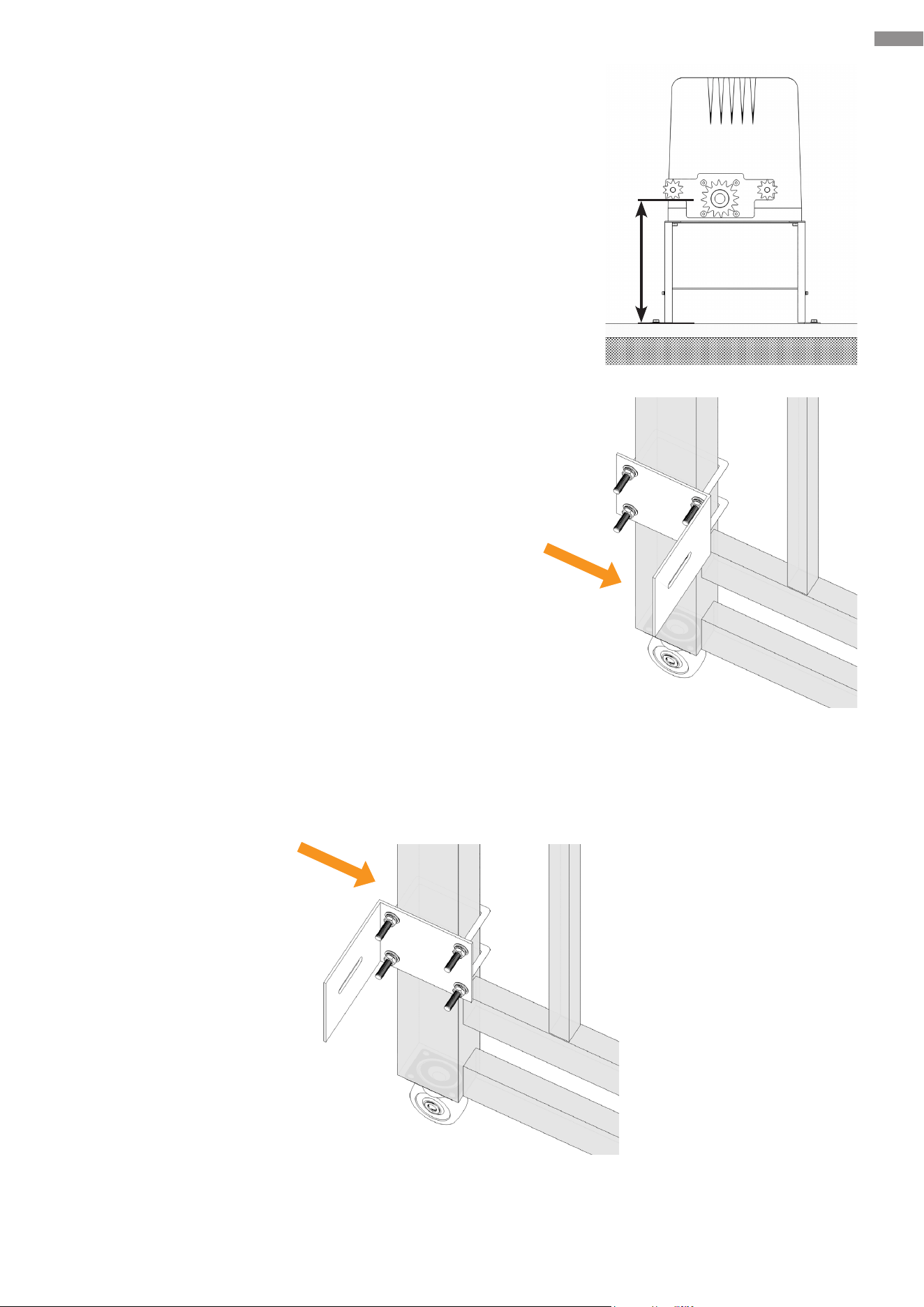
1. Determine the height of the marked idler wheel using
a tape measure (not included). This value represents
the mounting height of each chain bracket based
upon its horizontal centerline. On your gate, mark the
mounting height for both chain brackets.
2. Depending on your gate frame style, use the provided
arched or square U-bolts to secure the chain brackets
to the previously marked locations.
If neither of the U-bolts suits your gate frame, opt for
other appropriate fasteners.
• Chain Brackets (×2)
• Arched or Square U-bolts (×4)
• M6 Flat Washers (×18)
• M6 Spring Washers (×8)
• M6 Hex Nuts (×8)
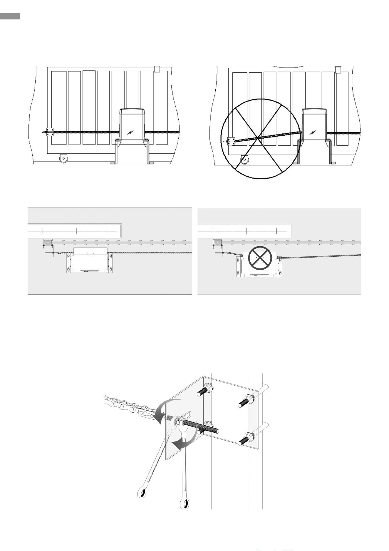
It is recommended that you position the brace for the chain bolt on the side of the gate frame
nearer to the motor (as shown in the image above), but it can be used in an alternative position
if necessary (as shown below).
21
Mechanical Installation
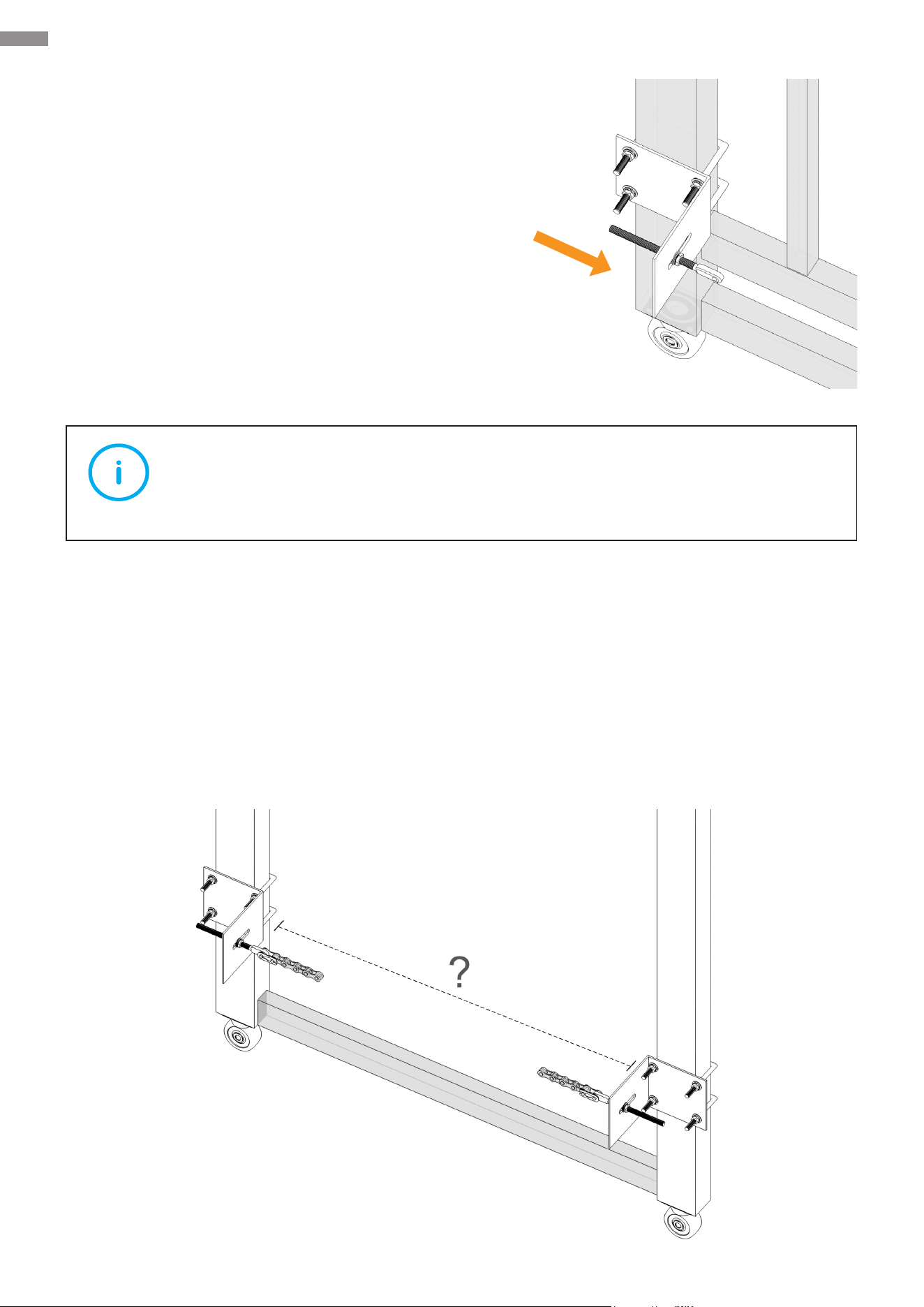
3. Attach the M8 bolts to the chain brackets as shown.
Fine tune the pins on the brackets as needed.
• M8 Bolts (×2)
• M8 Hex Nuts (×4)
• M8 Spring Washers (×4)
• M8 Flat Washers (×4)
Note
Do not tighten these fasteners completely for now.
4. Measure the distance between the two chain brackets as shown to see the necessary length
of the chain’s extension. This package includes two chains, each 9.8 feet (3 m) long.
• If the distance is 9.8 feet (3 meters) or less, cut o the excess chain section while leaving
a certain amount as needed.
• If the distance is 9.8–19.6 feet (3–6 meters), join the two chains and make your cut as
above.
• If the distance is 19.6 feet (6 meters) or more, use a #41 galvanized chain (not included).
22
Mechanical Installation
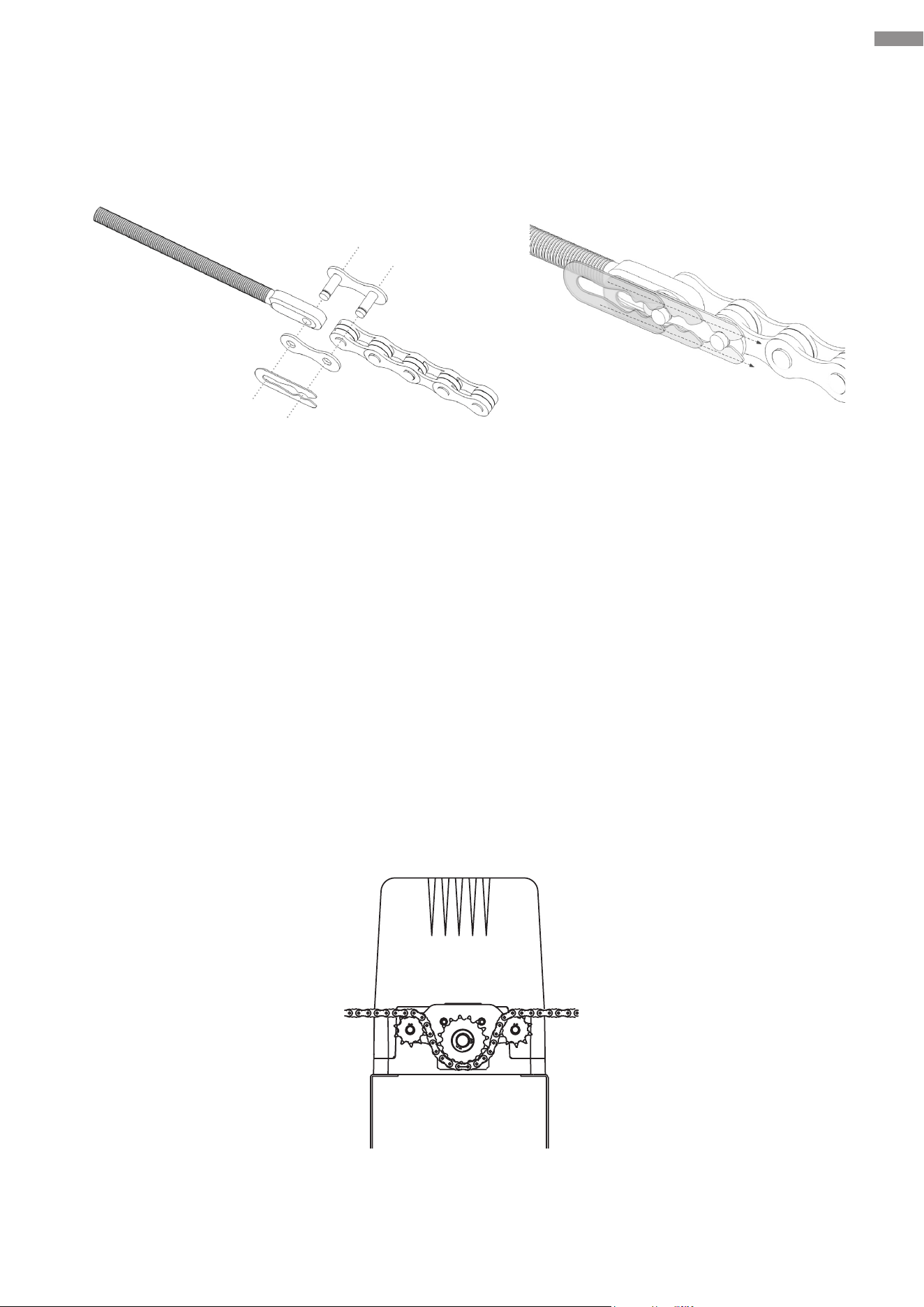
5. Install the chain adjacent to the main unit.
Connect both ends of the chain using either of the provided chain joints, pressing the clip into
place with pliers (not included) as shown.
6. Unscrew the locking bolts from the chain box and then remove its protective cover. Run the
chain through the chain sprocket and idler wheels. See illustration.
Check that the chain between the gate post and the idler wheel is level; if not, adjust the height
of the chain bracket.
Chain Bolt and Chain Joint Fixation
23
Mechanical Installation
7. Pull the chain onto the other bracket. Repeat Steps 5–6 to complete the connection and
installation. If necessary, ne tune the M8 bolts to achieve your desired positioning.
8. Adjust the nuts on each M8 bolt until your preferred tension is reached. Cut o any excess
chain section if needed.
Front View
Top View
24
Mechanical Installation
5.5 Chain Test
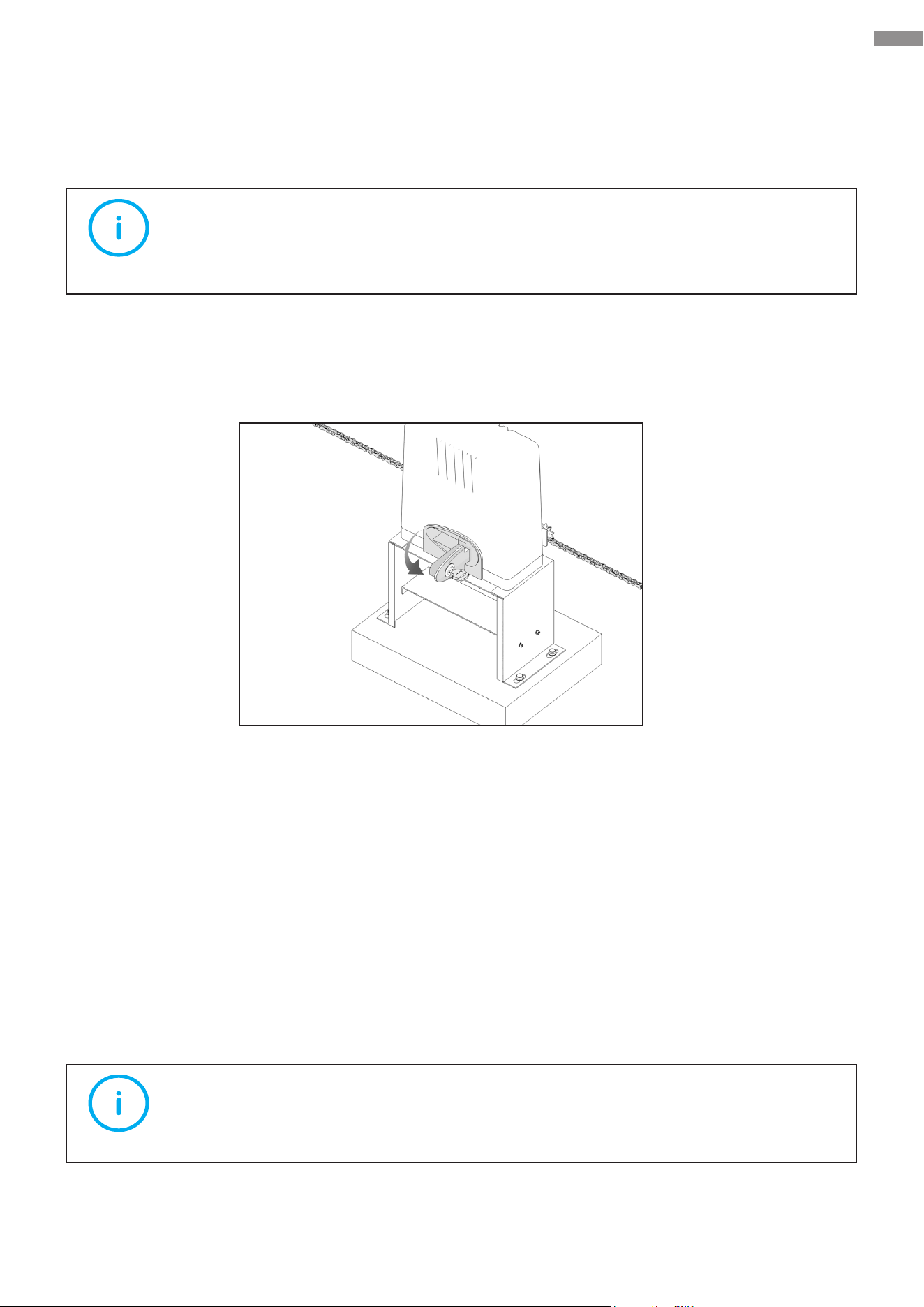
1. Unlock the motor to enable manual control mode.
Insert either manual key and turn it 90° clockwise. Then, pull the release lock to its maximum
extent and the sprocket is separated from the shaft and is free to rotate.
2. Manually slide your gate, checking that it moves smoothly. If necessary, reposition the main
unit or chain or replace the chain with a suitable one as mentioned above.
3. Push the release lock back into place and deactivate manual mode.
5.6 Chain Box Cover Reinstallation
Making sure the chain is correctly installed and operates in a smooth way, reinstall the removed
protective cover onto the chain box using its fasteners.
Note
This device is equipped with manual control mode. Only activate this mode in case
of power loss or for emergency.
Note
Tighten all fasteners to lock the protective cover in place.
25
Electrical Component Installation
6. Electrical Component Installation
This chapter introduces electrical connection operations
required for installing the gate opener.
Please follow the instructions for installation.
6.1 Important Information
• Wear appropriate PPE and obey the following instructions to prevent personal injury.
• Check that earthing is carried out correctly for all metal parts.
6.2 Circuit Connection Methods
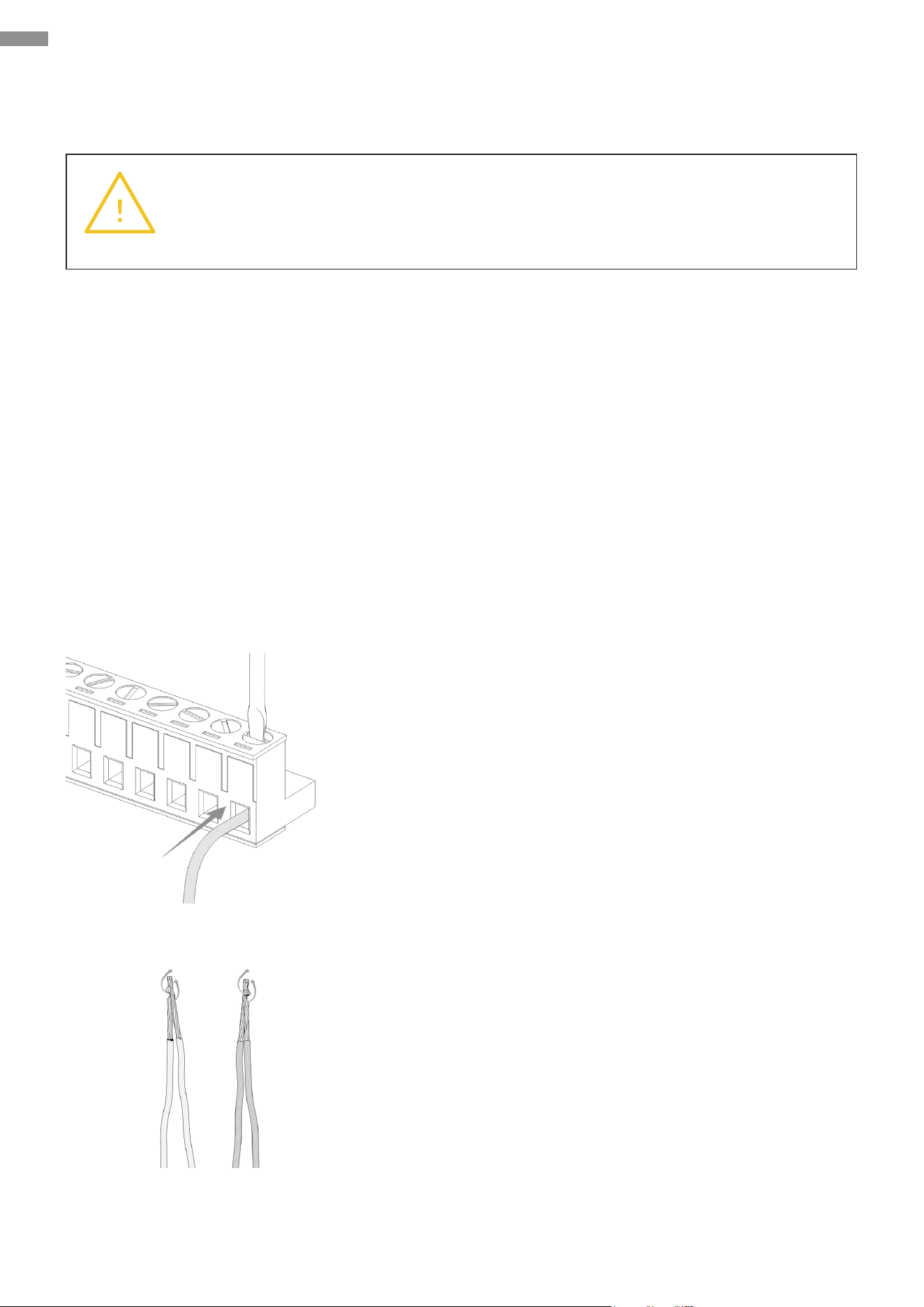
Connection to Terminals
Insert the exposed metal part of each cable into the right
terminal and tighten the corresponding athead bolt to
secure this connection.
Extension
Use electrician’s pliers (not included) to tightly twist the
exposed metal parts of the two cables together and then
wrap them with electrical tape around three times for
optimal coverage. The tape’s width should be greater
than the lengths of the metal parts.
Warning
Make sure ALL exposed wires are TIGHTLY twisted and FULLY inserted into the
terminals WITHOUT loose strands.
26
Electrical Component Installation
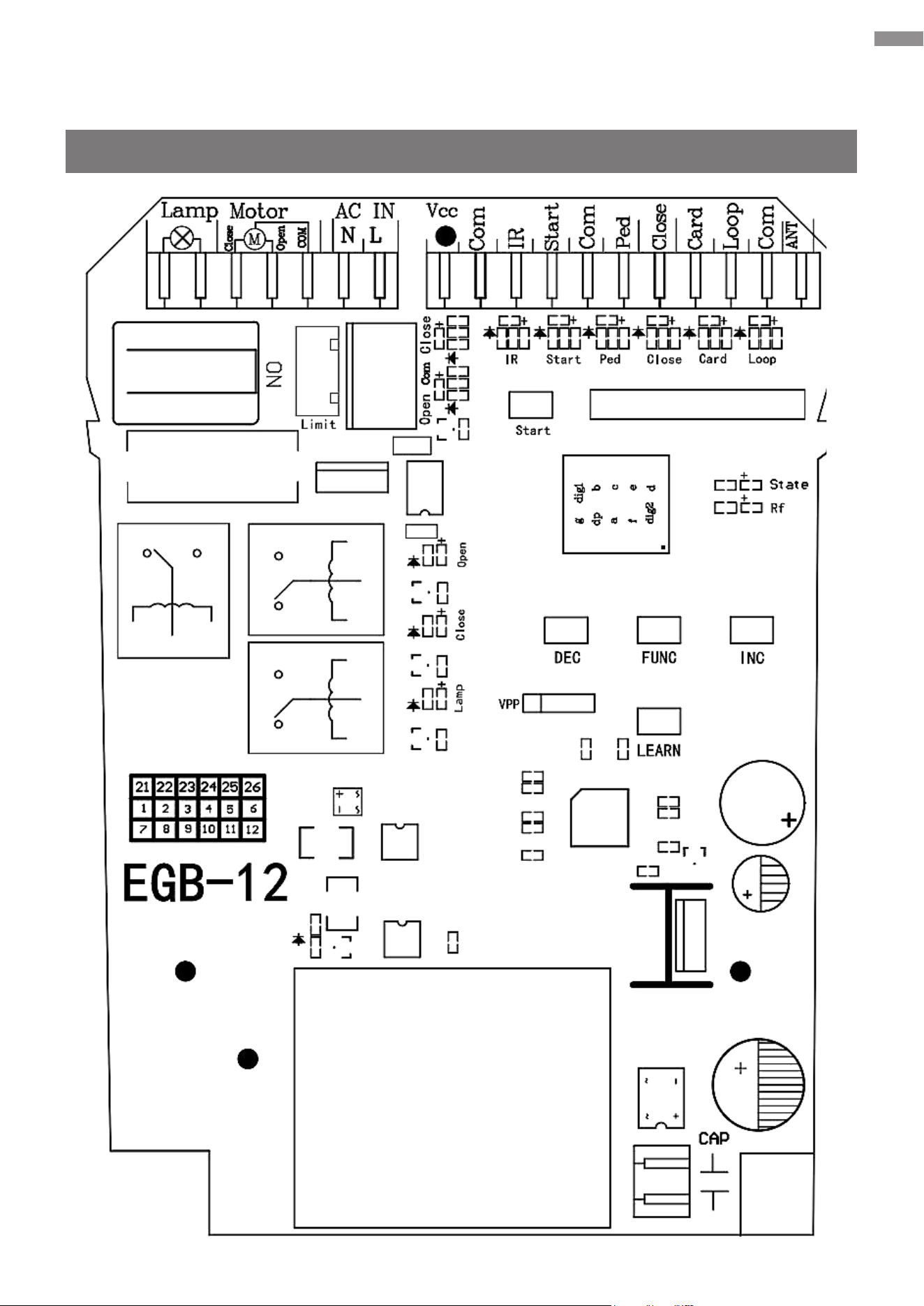
6.3 Control Board Description
Overview
27
Electrical Component Installation
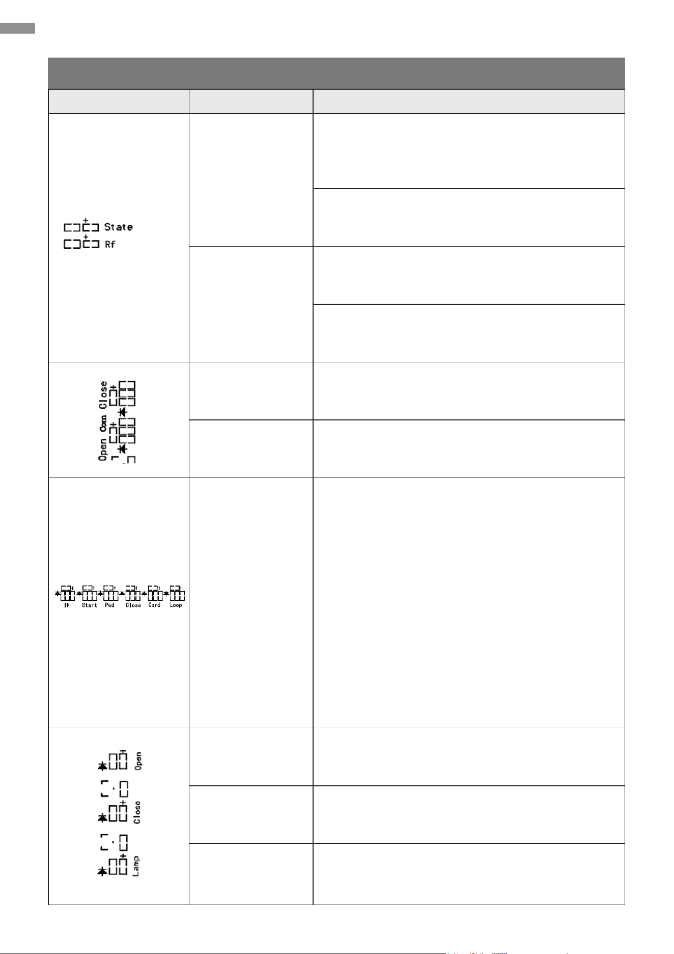
Indicator Lights
Item Name Description
System Status
(“State”, red)
Turns on upon the system’s initialization after
power-on and remains on if the system is operating
normally
Flashes once every 1 second during the closing
countdown
Radio Frequency
(“Rf”, blue)
Provides instructions including code learning and
clearing
Flashes rapidly upon receiving a custom rolling
code signal, whether it has been learned or not
Closing Limit
Signal (“Close”)
Turns on when the closing limit switch is triggered
Opening Limit
Signal (“Open”)
Turns on when the opening limit switch is triggered
Signal Terminal
• “IR”: Infrared sensing signal, which turns red
when detecting an obstacle and remains o
otherwise by default and vice versa if the PA
value is set to “1” (For the PA setting, refer
to Function Conguration—Advanced
Conguration—Parameter Adjustment.)
• Upon receiving a signal, the corresponding
indicator will light up.
“Start”: Loop control signal
“Ped”: Pedestrian mode signal
“Close”: External device closing signal
“Card”: Card swiping signal
“Loop”: Loop detection (ground sensing) signal
Gate-Open Signal
(“Open”, blue)
Turns on when the gate is opening
Gate-Close Signal
(“Close”, red)
Turns on when the gate is closing
Warning Light
(“Lamp”)
Turns on when the warning light is activated
28
Electrical Component Installation
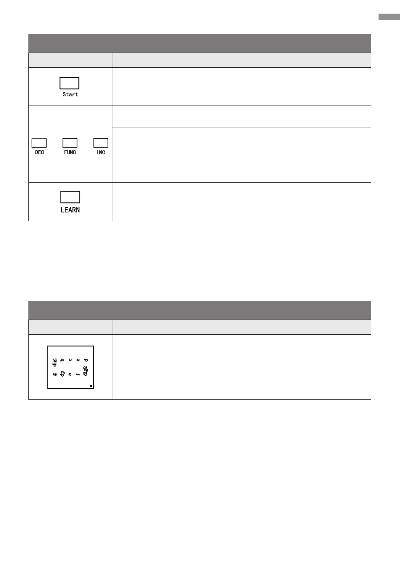
Control Buttons
Digital Display
Item Name Description
Starting Button (“Start”)
Activates the preset mode, causing your
gate to open, stop, and close alternately
Decrease Button (“DEC”) Decreases values
Function Button (“FUNC”)
Opens setting menus, conrms changes,
and saves data
Increase Button (“INC”) Increases values
Learning Button (“LEARN”) Programs or removing the remote control
Item Name Description
Digital Display Displays values
29
Electrical Component Installation
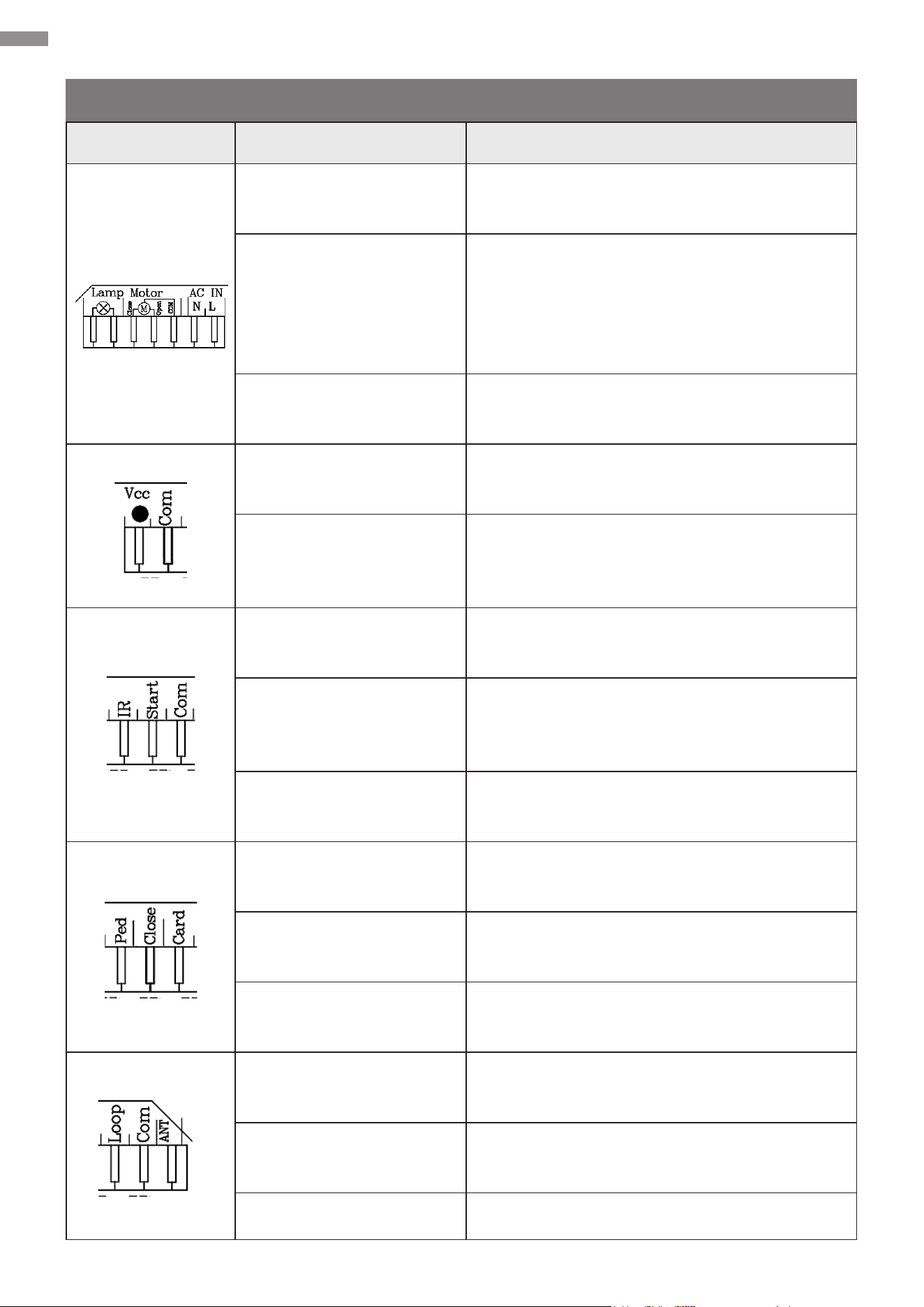
Interfaces
Interface Name Description
Warning Light Ports
(“Lamp”)
Warning light power control (AC power
output)
Motor Communication
Ports (“Motor”)
“Com”: Common terminal of AC motor power
supply
“Open” and “Close” determine the opening
direction of the gate opener (either right to
left, or left to right).
AC & IN Power Supply
Ports (“AC IN”)
“N”: AC power neutral line input
“L”: AC power live line input
Voltage-at-the-Common-
Collector Port (“Vcc”)
Positive terminal of 12V DC power supply
(actually 17–20V, max. 200 mA)
Common Terminal 1
(“Com”)
Grounding terminal as the trigger source for
signal ports or negative terminal of the power
supply above
Infrared Sensing Port
(“IR”)
Infrared signal input port for connecting
external infrared sensors
Loop Control Port
(“Start”)
Loop control signal input port for connecting
to external devices such as push buttons,
wired keypads, receivers, etc.
Common Terminal 2
(“Com”)
Signal input port for connecting with COM or
GND terminal.
Pedestrian Mode Port
(“Ped”)
Pedestrian mode (gate opening) signal input
port
Gate-Close Port (“Close”)
Gate closing signal input port for connecting
with external devices that will close the gate
Card Port (“Card”)
Card swiping signal input port for connecting
with external devices that will open the gate
Loop Detection Port
(“Loop”)
Vehicle detection signal for connecting with a
loop detector (ground sensor)
Common Terminal 3
(“Com”)
Signal input port for connecting with COM or
GND terminal.
Antenna Port (“ANT”) Remote control antenna port
30
Electrical Component Installation
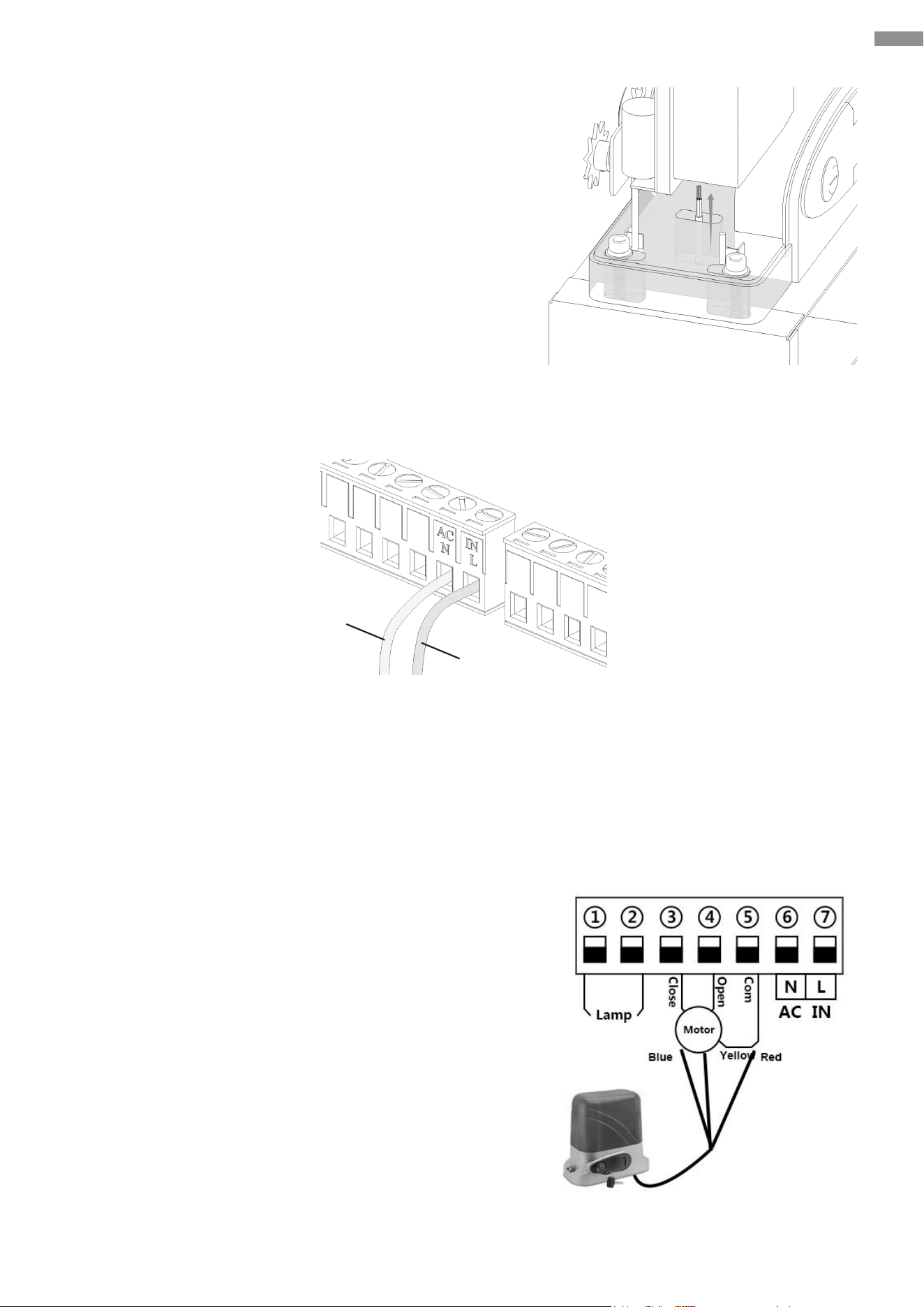
6.4 System Powering
This device is compatible with 110V AC 60Hz power
sources.
1. Use conduits to protect the electrical cables and
then thread one end of the cables connected to the
gate opener through the hole in the base.
2. Strip both ends of the cables to an appropriate length
of inner double-core cores using wire strippers (not
included).
3. Open the control board’s protective cover, connect the neutral wire of the power line to the “N”
terminal, and connect its live wire to the “L” terminal.
4. Connect the other end of the power line to the power plug. Choose a compliant product that
matches your local power supply for the plug.
6.5 Direction Reversal
This device is designated for immediate use with gates
that slide open to the right.
The motor cables are already preconnected as shown.
Ports 3 and 4 determine the opening direction of the
gate opener (either right to left, or left to right). Port 5 is
designated for COM or GND connection.
If your gate slides open to the left, recongure the
motor cables as follows.
1. Disconnect the motor cables from the main control
board.
2. Swap the cables that were previously connected
to Ports 3 and 4. Then establish new complete
connections.
Black
Red
31
Electrical Component Installation
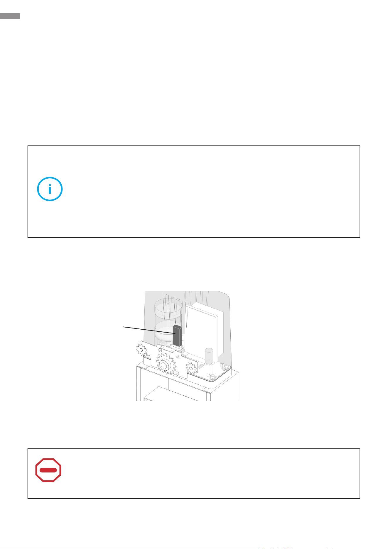
6.6 Limit Switch Magnets
This product employs magnetic limit switches to achieve distance limitation of a gate’s movement
during the process of opening or closing. After the gate reaches its intended position, its motor
automatically stops.
This product includes two magnetic components, one in blue and the other one in red, which are
corresponding to their identically colored indicator lights—blue for opening and red for closing.
Install these magnets onto your gate. As the gate moves, these magnets will pass the opener and
be detected by the sensor inside the opener immediately, causing the opener to stop operating so
as to accomplish the limit eect.
Note
The description above is applicable to gates that slide open to the right. For a left-
slide-open gate,
•
Swap the gate-close and gate-open cables. Refer to Electrical Component
Installation—Direction Reversal for detailed instructions.
•
Swap the limit switch magnets as needed for ease of debugging and operation.
To t the structure of the internal sensor, install the red magnet at a higher position and the blue
magnet at a lower position within its sensing range, ensuring the distance between the two
magnets are not too small.
Follow these steps for your installation. For ease of debugging, remove the protective cover from
the control board and connect this device to power.
Caution
The magnetic limit components provide strong magnetism. When handling them,
exercise caution to prevent pinching.
Internal Sensor
32
Electrical Component Installation
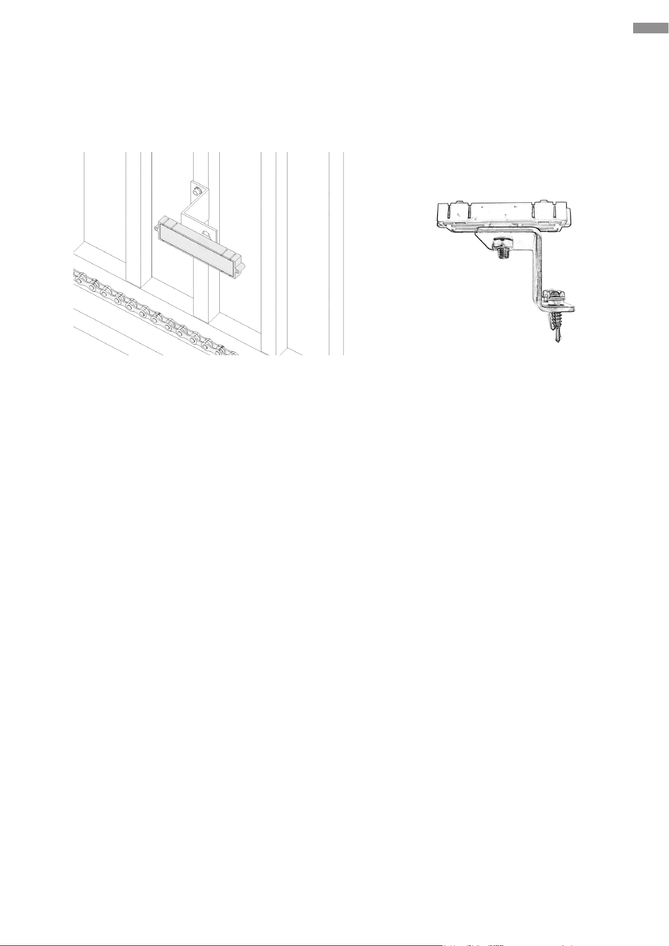
1. Install the gate-open and gate-close limit switch magnets separately on the magnet bracket.
You can adjust their positions as needed during the subsequent processes.
2. Install the gate-close limit switch magnet. Close the gate completely and determine the exact
position for installation.
Note: To ensure safe use, the magnet bracket should ideally be installed at the center of the
gate’s rail and should NOT be positioned too close to the edge.
Place the magnet bracket assembly (with the long side of the limit switch magnet parallel to the
ground) onto the intended installation position. If the “Close” limit indicator light on the control
board comes on, mark the installation hole positions using a pen or other proper instruments.
If it does not come on, adjust the installation position.
3. Drill holes and secure the magnet bracket to the gate pillar using its fasteners.
4. Install the gate-open limit switch magnet. Open your gate to its maximum position and place the
magnet at an appropriate location as described in Step 1. Ensure the magnet is not positioned
too close to the edge of the gate’s rail and adjust the maximum open position if necessary.
5. When nished, use the gate opener to perform an open-and-close test to ensure the correct
installation of the limit switch magnets.
33
Electrical Component Installation
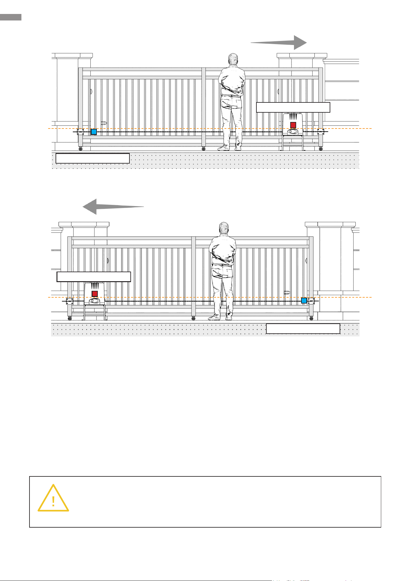
6.7 Fixation
Mark the locations of the mounting holes and then place everything in a safe place nearby.
Warning
The motor must be rmly secured for safe use. Do not attempt to use it when the
base is loose or only secured to thin pavement.
Right-Slide Opening
Left-Slide Opening
Gate-Open Magnet
Gate-Open Magnet
Gate-Close Magnet
Gate-Close Magnet
34
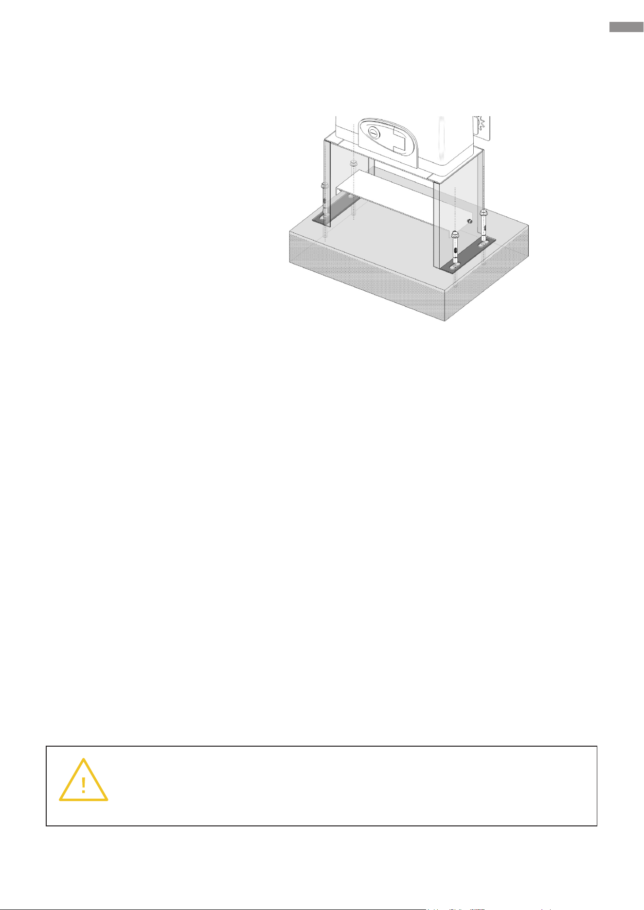
Electrical Component Installation
Warning
If you notice that the concrete footing shakes with the gate opener during use, add
extra concrete or further secure the base as needed.
If the area is covered by concrete that is no less than 10 inches (25 cm) thick, drill four matching
holes and fasten the base to the ground using the provided anchor bolts.
Necessary Tool and Fastener:
• Power Drill
• M10×80 Anchor Bolts
If the area has no suitable concrete, to ensure a sturdy and reliable connection between the gate
opener and the ground, it is recommended to pour a rectangular concrete footing rst. Then,
following the methods mentioned earlier, install the gate opener components onto the concrete
footing. The steps for pouring are as follows.
1. Based on the hole positions marked in the previous step, plan the location on the surface of
the concrete footing on the ground. Checking that the concrete footing does not interfere with
the gate’s normal operation, try to position it closer to the gate to ensure the gate opener can
be installed in an appropriate location.
2. Dig a hole that is 20 inches (50 cm) wide, 14 inches (35 cm) long, and 8 inches (20 cm) deep.
3. Prepare a mold box of the same dimensions and place it into the hole. You can use a non-stick
spray to minimize moisture absorption and facilitate future removal.
4. Fill the mold box with concrete, ensuring a smooth and even top surface. You will need at
least 1.25 cubic feet (35 L) of concrete (equivalent to about the volume of three standard
60-pound bags or slightly more than the volume of two standard 80-pound bags). For further
reinforcement of the concrete footing, you can place a metal wire frame near its sides.
5. Wait for at least 24 hours and protect the area from the elements to allow the concrete to set
properly.
6. Remove the mold box from around the concrete and compact the soil rmly back into place.
Adjust the footing as needed to ensure it ts snugly, remains securely positioned, and has a
completely level top surface.

35
Electrical Component Installation
6.8 Infrared Equipment Connection (SGO-1801-GY Only)
1. Connect Ports 12 and 10 to the “COM” and “OUT” ports of the receiver respectively.
2. Prepare two more two-core wires. First, connect one end of either to the positive (“+”) and
negative (“−”) terminals of the receiver. Then, connect the other in a similar manner to the
positive and negative terminals of the transmitter.
3. Prepare the other ends of the wires, align the positive to positive and negative to negative, and
twist them together.
4. Connect the positive wires of both the transmitter and receiver to Port 8. Connect their negative
wires to Port 9.
5. Secure the transmitter and receiver to the gate pillar using their fasteners.
• The installation height should be at least 65.6 feet (20 meters).
• Pay attention to the labeling on the transmitter and receiver during installation. Do not
place them upside down.
• Ensure both the transmitter and the receiver are vertically installed.
• Ensure the transmitter and receiver are aligned along the same horizontal line.
6. Secure the casing of the transmitter and receiver using their locking bolts.
If you have purchased SGO-0000-01 and SGO-EC06-02, you can optionally install an infrared
sensing device as needed. The wiring methods provided above are for your reference, but for
specic installation instructions and precautions, follow the manual provided with the infrared
equipment you have purchased.
T means Transmitter and R means Receiver
36
Electrical Component Installation
6.9 Wire Connection Guidance of Optional Accessories
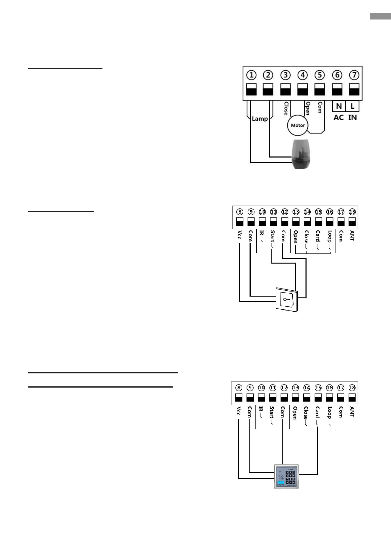
Warning Light
You can choose to connect a warning light to Ports
1 and 2. When the gate is in motion, the light will
ash. When the gate stops, the light will turn o.
Push Button
You can also use an additional manual switch (push
button) to issue gate opening commands. Connect
its power inlets to Ports 8 and 9 and its control
signal interfaces to Ports 11 and 12 as shown.
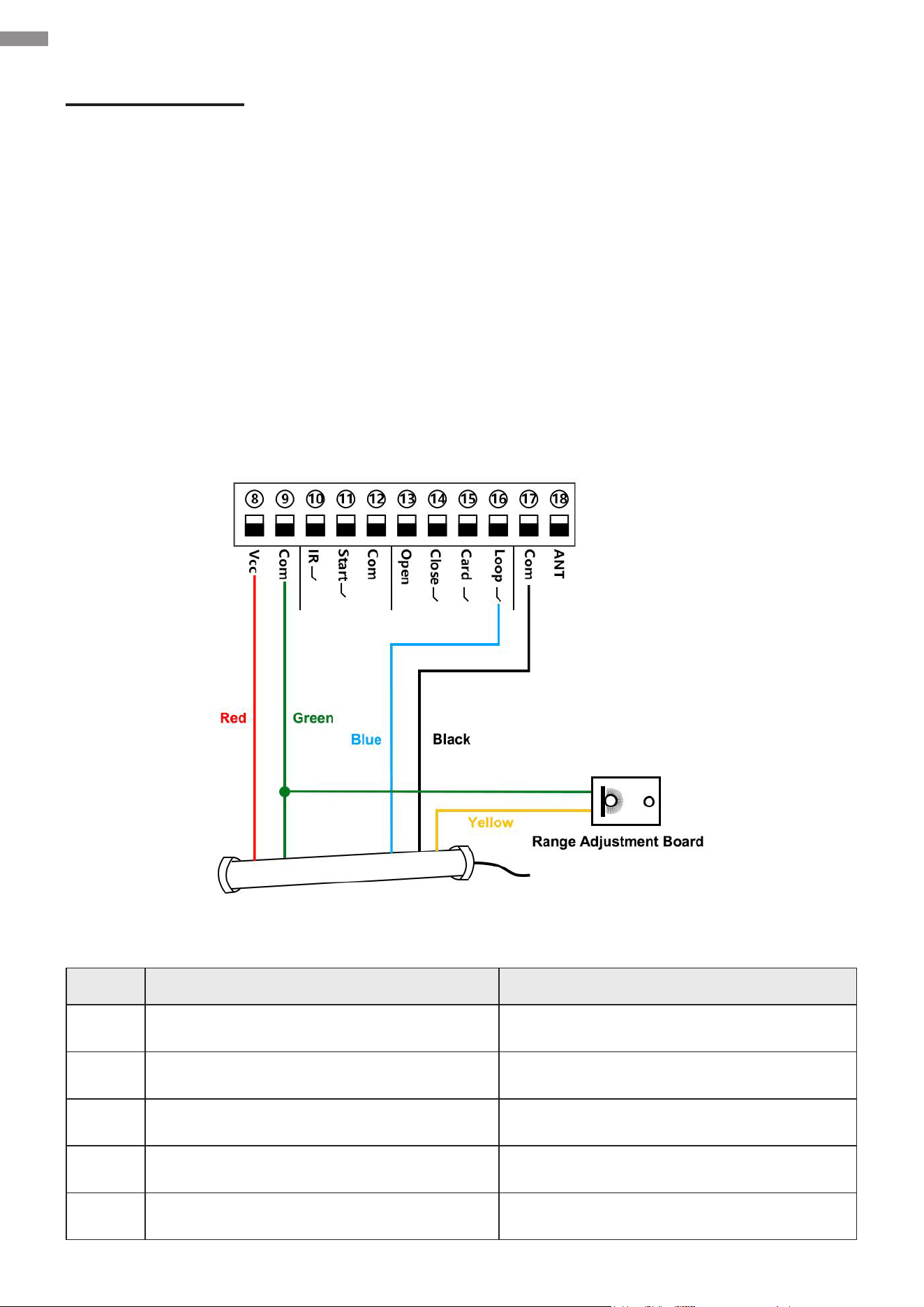
Swipe Card, Digital Keypad,
and Other External Devices
You can choose to install external devices,
allowing personnel access to your property using
an identication code or card that you provide.
Terminal 15 is designated for gate opening only.
Terminals 12 and 15 are designated for connecting
external access control devices (such as swipe
cards and wired digital keypads) and for opening
gates only.
Terminals 8 and 9 are for supplying power to swipe
cards.
Flashing Light
Push Button
Swipe Card
37
Electrical Component Installation
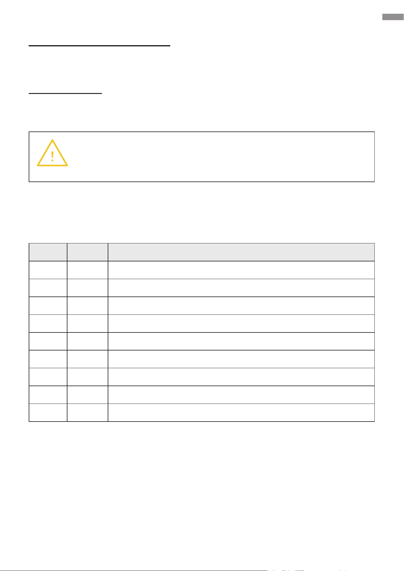
Loop Detector
You can install a loop detector (i.e., vehicle detector or ground sensor) to enhance the convenience
of using the gate opener.
If the gate opener receives a signal from the loop detector when your gate is opening or at its fully
open position, it will hold the gate where it is. 2 seconds after no signal is received, the gate will
close.
If the gate opener receives a signal from the loop detector while your gate is closing, it will move
the gate back to its maximum opening position. 2 seconds after no signal is received, the gate will
close.
The loop detector and its accompanying devices need to be purchased separately. Installation
should comply with its user manual.
Circuit Connection for Loop Detectors
Denition of the 5 Colored Cables
Color Usage Connection
Red Input Voltage (+) Terminal 8
Black Relay’s Common Terminal 17
Green Ground/Common (−) Terminal 9 and Range Adjustment Board
Blue Relay’s Normally Open Terminal 16
Yellow Range Adjustment Potentiometer (POT) Range Adjustment Potentiometer (POT)

38
7. Operation
7.1 Remote Control Description
The system can support 120 remotes at most. Each of the
provided remote control is as below.
The remote control applies three-button control mode by
default and can be toggled to single-button control mode. Refer
to Function Conguration—Advanced Conguration—
Parameter Adjustment for setting P7 to toggle this. When
nished, the codes need to be relearned.
Three-Button Control Mode
Button 1: Opens the gate
Button 2: Closes the gate
Button 3: Stops the gate movement
Button 4: Activates or deactivates
pedestrian mode
Single-Button Mode
Button 1: Opens or closes the gate
Button 2: Activates or deactivates pedestrian mode
Button 3: Opens or closes the gate
Button 4: Activates or deactivates pedestrian mode
In this mode, you can program Buttons 1 and 2 to operate
one gate opener and Buttons 3 and 4 for another gate
opener.
Note: Pressing Button 1 or 3 opens and closes your gate alternately. For instance, if the gate is
open, your rst press will close it and second press will reopen it.
7.2 Functions
Main functions of the system are as follows.
Movement Limitation
The motor stops running when the gate reaches its opening or closing limits.
Mechanical Obstruction Feedback
This function only operates during high-speed movement and will not be triggered if it is slow.
If an obstruction is encountered during the opening process, the gate opener stops the gate. If
an obstruction is encountered during the closing process, the gate opener reverses the gate’s
movement, providing anti-pinch protection.
The gate opener’s obstruction sensitivity is adjustable. A smaller value makes your gate more
sensitive to obstructions while a larger value reduces the degree. Refer to Function Conguration —
Advanced Conguration—Parameter Adjustment for details. The larger you set the value, the
stronger the gate’s force against obstruction and the less sensitive the gate opener to activate its
anti-pinch protection during high-speed movement.
Operation

39
Infrared Obstruction Feedback
The transmitter emits infrared light. If an obstacle is encountered, some of the infrared light will be
reected to the receiver. While your gate is closing, if the receiver detects an infrared signal, the
gate will reverse and reopen until it is in the designated position. 2 seconds after the infrared signal
disappears, the gate will automatically close.
Automatic Closing
Automatic closing functions only after your gate’s opening limit has been triggered. Once the auto-
close countdown begins, the “State” indicator light will ash once per second. The gate will close
after the countdown ends and the infrared signal has disappeared for 2 seconds.
You can adjust the auto-close countdown time through the menu settings.
Pedestrian Mode
When the remote control activates pedestrian mode using Button 2 or 4, your gate will automatically
open. If you have enabled the auto-close function in pedestrian mode, the gate will enter an auto-
close countdown after reaching the opening limit and will automatically close when the countdown
ends.
The auto-open and close countdown times for the gate can be adjusted through the menu settings.
Note: Pedestrian mode only operates when the gate is at the closing limit position. The set opening
time in pedestrian mode cannot exceed the gate’s opening travel time.
Vehicle Detection
If the gate is at the opening limit position or is in the process of opening and the loop detector
(ground sensor) detects a vehicle passing by, the gate opener will perform an automatic closing
action 2 seconds after no signal is received. If the gate is in the process of closing and a vehicle is
detected, the gate opener will immediately reverse the gate’s movement. 2 seconds after no signal
is received, the gate opener will perform an automatic closing action.
Note: You can disable the auto-close function of the loop detector through the menu settings.
Travel Learning
After the low-speed operation time is set, the travel learning function allows the system to allocate
periods of low-speed and high-speed operation during one complete cycle of gate opening and
closing.
Low-Speed Operation Time: As approaching the limit position, the gate transitions to slow-speed
operation during a specied period of time, i.e., the low-speed operation time. The default setting
is 2 seconds, which means the gate will start decelerating and enter low-speed operation for 2
seconds before reaching the limit position.
Operation
40
Operation
Motor Running Protection
The motor will automatically stop running after continuous operation for 90 seconds.
Manual Mode
This mode allows manual operation to replace intelligent control in case of power failure or other
unexpected situations. Use the emergency release key for activation or deactivation.
Warning
ONLY use the emergency release key when the gate is not moving or the device is
disconnected from power.
7.3 Code Display
No. Code Description
1 OP Gate opening
2 CL Gate closing
3 -- Gate stopping
4 LO Gate at its full opening limit
5 LC Gate at its full closing limit
6 PD Pedestrian mode activated
7 OU Motor running protection triggered
8 PH Photocell activated
9 LP Loop detector (ground sensor) activated
Use the control board’s buttons and the remote control to adjust function settings. After the system
is powered on, a beep will sound and the digital display will show the model and software version.
The “State” indicator light should remain on, indicating the normal functioning of the system.

41
7.4 Basic Function Conguration
Accessing the Setting Menus
Hold FUNC until “P0” is displayed, opening the setting menus.
Selecting Menus and Adjusting Values
Use INC+ or DEC− to select a menu and increase or decrease a value.
Conrming Selections and Saving Changes
After adjusting a value, press FUNC to conrm and save your change. Then a beep should sound
to indicate success.
Exiting the Setting Menus
When nished, press LEARN to exit the menus and turn o the display.
7.5 Advanced Function Conguration
Learning Codes (Remote Control Learning)
The remote control must be successfully learned before use. Press RF and its indicator light should
turn on. Press your preferred button on the remote control, and a short buzz will sound, indicating
successful code learning. The digital display will show the number of the learned remotes.
Note:
• A maximum of 120 remotes can be learned. Since the digital display can only show two digits,
numbers between 100 and 109 will display as "A" for the rst two digits (e.g., “A8” for 108) and
numbers between 110 and 120 will display as "b" for the rst two digits (e.g., “b8” for 118).
• If “--" is displayed and 5 short buzzes sound, the storage space is full and no further learning
can be done.
• If the controller does not receive a signal from the remote control within 8 seconds after
LEARNING is pressed, the indicator light will turn o and the system will deactivate the learning
mode.
Clearing Codes
Clearing codes refers to removing the original remote control pairing code. Hold RF until a long buzz
sounds, lasting for approximately 5 seconds. After successful clearing, “00” should be displayed.
Note: Clearing codes will render all previously paired remote controls inactive. After each clearing,
relearning is required.
Operation

42
Travel Learning
While the system is at its closing limit position, hold INC and DEC simultaneously until a long buzz
sounds. The system should automatically cause the gate to open and close once and then a long
buzz should go o again, with low-speed and high-speed times being allocated and shown on the
digital display.
Note:
• If the system is not in its closing limit position before starting learning, two short buzzes will
sound, indicating that learning cannot be initiated.
• During travel learning, the remote control, obstruction feedback, loop detector (ground sensor),
external digital keypads, etc. cannot function.
• If a single travel lasts for less than 5 seconds, 2 buzzes will go o, indicating the learning has
failed.
• Alternatively, you can activate travel learning through the setting menu. For details, refer to the
digital display settings explanation below.
Parameter Adjustment
Parameter Function
Custom
Value
Default
Value
Description Remark
P0
Limit signal
mode
0 & 1 1
0: Normally On
1: Normally O
No user
conguration
required
P1
High-speed
obstruction
sensitivity
0–20 12
The smaller the value,
the higher the obstruction
sensitivity
The larger the value, the
lower the sensitivity
P2
Low-speed
operating time
(sec.)
0–5 sec. 2
0: No low-speed operation
time but full-time high-
speed
P3
Auto-close
time for swipe
cards (sec.)
0–99 10
0: O
1: Minimum value required
P4
Auto-close
time in
pedestrian
mode (sec.)
0–99 10
0: O
1: Minimum value required
Operation

43
Parameter Adjustment
Parameter Function
Custom
Value
Default
Value
Description Remark
P5
Auto-close
time in
standard mode
(sec.)
0–99 0
0: O
1: Minimum value required
P6
Auto-open
time in
pedestrian
mode (sec.)
0–20 5
0: O
1: Minimum value required
P7
Remote control
modes
0 & 1 0
0: Three-Button Control
1: Single-Button Control
P8
Warning light
output
0 & 1 1
0: O 30 seconds after
the gate is fully closed and
otherwise on
1: On while the gate is in
motion and o when it is
closed
P9
Loop detector
(ground
sensor)
activation
0 & 1 1
0: Disables the auto-close
function
1: Enables the auto-close
function, causing the gate
to start closing 2 seconds
after the loop detector
trigger signal disappears
No impact on
gate opening
PA Infrared input 0 & 1 0
0: Infrared outputs
normally open (NO) signal
when there is no obstacle
1: Infrared outputs normally
closed (NC) signal when
there is no obstacle
P- Travel learning 0–10 0
Select “5” and conrm, a
long buzz will sound.
Note: Only “5” is
selectable. Any other
number will be invalid.
Po Reset 0–10 0
Select “5” and conrm, a
long buzz will sound.
Note: Only “5” is
selectable. Any other
number will be invalid.
Operation
44
8. Troubleshooting
If any component of the system is known or suspected to malfunction or be improperly adjusted,
DO NOT use before professional servicing is completed. Using with malfunctional or improperly
adjusted components may pose safety risks.
The following table outlines common problems and their respective standard solutions. Consult
this table to address any encountered problems as needed. For substantial modications to the
device, seek professional assistance from trained technicians.
If this table cannot resolve your problem, discontinue use of this device and unplug it. Seek
professional servicing. Be sure to have the correct model number and prepare a detailed problem
description in advance to receive prompt and eective assistance.
Warning
• ONLY allow professional servicing by trained technicians.
• ONLY replace components with new identical ones.
• ALWAYS disconnect the device from power before performing any inspection
or servicing.
• To check voltage and continuity, use a multimeter. Exercise caution when
inspecting high-voltage terminals.
• When nished with any inspection or servicing, reinstall all removed protective
covers into place.
No. Problems Possible Causes Usual Solutions
1
The gate can only
slide open in one
direction.
Limit switch failure
Reposition the two magnets and try
again.
If this fails, hold the magnets against
the limit switches and test using a
multimeter. If it beeps, the limit
switches are functioning correctly. If
it does not, have the limit switches
replaced with new identical ones.
Incorrect circuit
connections for the infrared
sensor, etc.
Inspect the corresponding wiring.
Damage to any electrical
component on the control
board
Have the problematic component
replaced with a new identical one.
If necessary, have the control board
replaced.
Troubleshooting

45
No. Problems Possible Causes Usual Solutions
2
The gate cannot
open or close.
Power failure
Check that the power supply is
working properly. Seek professional
assistance if necessary.
Limit switch failure
Reposition the two magnets and try
again.
If this fails, hold the magnets against
the limit switches and test using a
multimeter. If it beeps, the limit
switches are functioning correctly. If
it does not, have the limit switches
replaced with new identical ones.
Loose circuit connections
Fully reconnect and retighten the
connections.
Motor damage
Seek professional servicing.
Have the motor replaced with a new
identical one if necessary.
Extended motor operation
leading to excessive
temperature, triggering
overheating protection
Allow the motor to cool for at least
20 minutes before continuing use.
Damage to any electrical
component on the control
board
Have the problematic component
replaced with a new identical one.
If necessary, have the control board
replaced.
3
The remote control
does not work.
Out-of-range positioning
Place the remote nearer to the gate
opener and try again.
Remote-receiver
incompatibility
Reprogram the remote.
Receiver damage
Have the receiver replaced with a
new identical one.
Battery outage
Replace the battery (12V23A) with
a new identical one and check that
the indicator light on the remote can
turn on.
If this fails, seek professional
assistance.
4
When the
programmed Button
1 or 2 is pressed for
opening or closing,
the gate stops
midway or returns to
its original position.
Insucient resistance
Increase the high-speed obstruction
sensitivity by adjusting the P1 setting
using the display panel.
Obstacle interference Remove the obstacles
Troubleshooting

46
Troubleshooting
No. Problems Possible Causes Usual Solutions
5
The gate stops
moving before fully
opening and does
not return to its
original position
Incorrect installation of limit
switch magnets
Correct their positions and try again.
Direction mismatch for a
left-slide-open gate
Adjust the cable connection
according to Direction Reversal.
Magnetic sensor misre
Enlarge the distance between the
two limit switch magnets.
6
The gate opens
normally but cannot
close.
Obstructed infrared sensor
(if any)
Remove the obstacle.
Limit switch failure
Reposition the two magnets and try
again.
If this fails, hold the magnets against
the limit switches and test using a
multimeter. If it beeps, the limit
switches are functioning correctly. If
it does not, have the limit switches
replaced with new identical ones.
Starting capacitor fault in
the motor
Have this capacitor replaced with a
new identical one.
Damage to any electrical
component on the control
board
Have the problematic component
replaced with a new identical one.
If necessary, have the control board
replaced.
7
The motor is
operating properly
while the gate is not
moving.
Non-engagement of the
manual release lock
Re-engage the manual release lock
using the provided keys.

47
9. Maintenance
• Keep the gate opener clean.
Disconnect this device from power and remove dirt or dust from its external surface using a
soft cloth wetted with water or a mild cleaning solution. Do not use harsh abrasive or caustic
chemicals and do not allow any electrical components to become wet. Also use a soft brush or
OSHA-compliant compressed air to clean out any vents and openings.
• Perform monthly testing, ensuring proper reaction to obstacles.
The gate MUST reverse upon contact with a solid object or halt when an object triggers the
non-contact sensors. After adjusting the force or travel limit, perform a retest. Failure to properly
retest following adjustments can heighten the risks of personal injury or even death.
• Inspect the items listed in the following form every six months.
This form is designated to facilitate your maintenance tasks. If encountering any issues, contact
the manufacturer or an authorized local contractor for assistance.
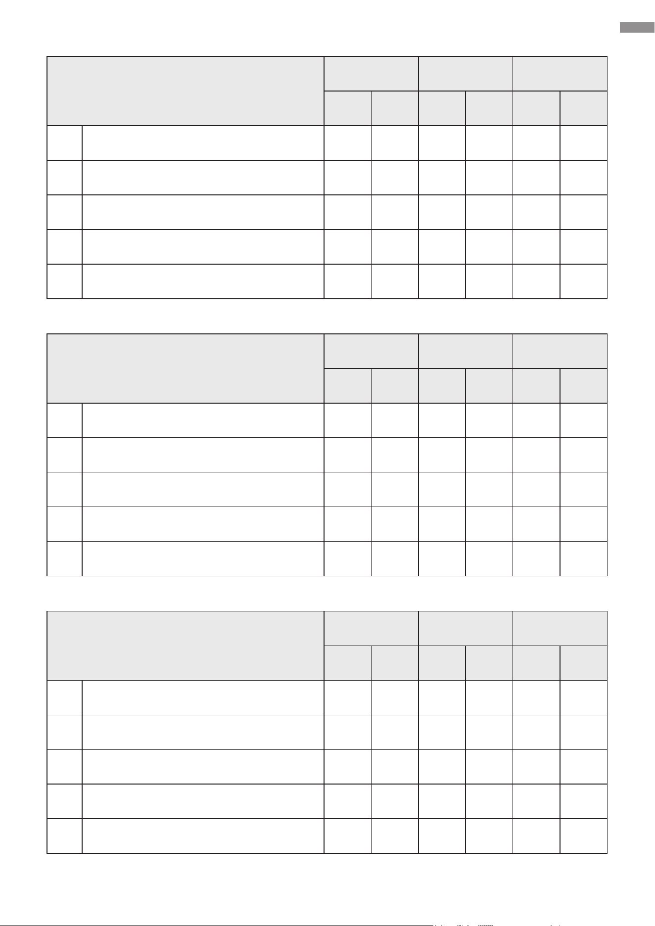
Item
Record Record Record
Result Date Result Date Result Date
1 Lubrication for moving parts
2 Loose anchor bolts
3 Loose or corroded wiring
4 Proper earthing and termination
5 Obstacle stop/reversal function
Maintenance Record Form
Maintenance
48
Maintenance
Item
Record Record Record
Result Date Result Date Result Date
1 Lubrication for moving parts
2
Loose anchor bolts
3 Loose or corroded wiring
4 Proper earthing and termination
5 Obstacle stop/reversal function
Item
Record Record Record
Result Date Result Date Result Date
1 Lubrication for moving parts
2 Loose anchor bolts
3
Loose or corroded wiring
4 Proper earthing and termination
5 Obstacle stop/reversal function
Item
Record Record Record
Result Date Result Date Result Date
1 Lubrication for moving parts
2 Loose anchor bolts
3 Loose or corroded wiring
4 Proper earthing and termination
5 Obstacle stop/reversal function

49
10. Disposal
11. Contact Us
Thank you for choosing our products! If you have any questions or comments,
contact us at contact@cssupportgroup.com and we'll resolve your issue
ASAP!
For a .pdf copy of the latest version of these instructions, use the appropriate
app on your smartphone to scan the QR code to the right.
Electrical products should not be disposed of with household products. In the
EU and UK, according to the European Directive 2012/19/EU for the disposal
of electrical and electronic equipment and its implementation in national laws,
used electrical products must be collected separately and disposed of at the
collection points provided for this purpose. Locations in Australia, Canada, and
the United States may have similar regulations. Contact your local authorities
or dealer for disposal and recycling advice.
SGO-0000-01
SGO-EC06-02
SGO-1801-GY
Rev. 1 Dec. 2023
Disposal & Contact Us