SLIDING GATE OPENER
USER MANUAL
V20230110
Read Carefully Before Use
Keep for Future Reference

1
• Read these instructions completely before installation and use. Provide them to any technician
used to install, maintain, or repair this device and provide them with the device if it is ever given
or sold to a third party.
• Install and use this gate opener only in accordance with these instructions and all applicable local
and national laws and regulations. Adding instructional or warning signage may be necessary
in your area. Only use the device for its intended purpose, opening and closing a single sliding
gate for vehicular trac. Always aim to minimize public exposure to potential hazards such as
pinch points. Failure to do so may result in serious property damage and severe personal injury.
• Install and use this gate opener only on rm level ground. Install and use this device so that
its motor and other hazardous components are not in public areas and protected as much as
possible from unauthorized access and use. There should be adequate clearance between
your gate and any nearby structures to prevent any possibility of a pinching or crushing hazard
during use. If this is impossible, the area should be guarded as well as possible and warnings
placed nearby.
• ONLY allow trained technicians to install and repair this device and its electrical connections.
Disconnect all power from electronic components during installation and maintenance except
as instructed for safely testing functionality.
• ONLY use this device for a single sliding gate intended for vehicular trac. Pedestrians should
be provided with a separate access point far enough away to ensure they never come into
contact with the moving vehicular gate.
• DO NOT install this device in any area prone to ooding or in locations exposed to ammable
or explosive fumes.
• ONLY use well-connected and maintained ANSI #41 chains with this device. Never use this
device for gates wider than 40 feet (12 m) and never allow the sprockets to carry the weight
of the gate. Keep the chain correctly positioned so all weight is distributed to the gate’s own
wheels during operation.
• ONLY install xed controls for the gate where they cannot be reached over, under, around,
or through the gate. They should also be far enough away that operators cannot contact the
moving gate during use.
• NEVER allow children to play on or around this device or its attached gate. Keep controls away
from children and out of their reach at all times and warn them of the gate’s danger.
• NEVER pair a remote control for this device with any other control board. Never attempt to
operate this device with two or more remotes or control devices at the same time.
• All provided components of this device are weatherproofed to withstand normal rain. Ensure
adequate insulation and protection of all electrical connections and never direct pressurized
water against any part of this device.
• Keep your gate well maintained and its track free of grime and debris. Periodically conrm that
it runs smoothly under manual operation.
• DO NOT use if any component is missing, loose, worn, or damaged. Tighten, repair, or replace
problematic parts before further use. Only replace components with identical parts and always
fully replace damaged electrical cords.
Warning!
Safety Information

2
Specications
Model 2700 3300
Input Power
110–120 V~ 60 Hz 110–120 V~ 60 Hz
Rated Power
0.54 hp 400W 0.74 hp 550W
Torque
16.2 lb.-ft. 22 N·m 23.6 lb.-ft. 32 N·m
Duty Cycle
S2 20 min. S2 20 min.
Max. Gate Weight
2700 lb.
1.35 T
1200 kg
1.2 MT
3300 lb.
1.65 T
1500 kg
1.5 MT
Max. Gate Speed
42.5 fpm 13 m/min. 42.5 fpm 13 m/min.
Max. Gate Length
20 ft. 6 m 20 ft. 6 m
Max. Noise
60 dB 60 dB
Min. Temperature
−4°F −20°C −4°F −20°C
Max. Temperature
158°F 70°C 158°F 70°C
Weatherproong
IP44 IP44
IR Signal
940 nm 1.9 kHz 940 nm 1.9 kHz
IR Sensor Range
6.6
–
65.6 ft. 2
–
20 m 6.6
–
65.6 ft. 2
–
20 m
Max. Remotes
25 25
Remote Range
98.4 ft. 30 m 98.4 ft. 30 m
Remote Frequency
433.92 MHz 433.92 MHz
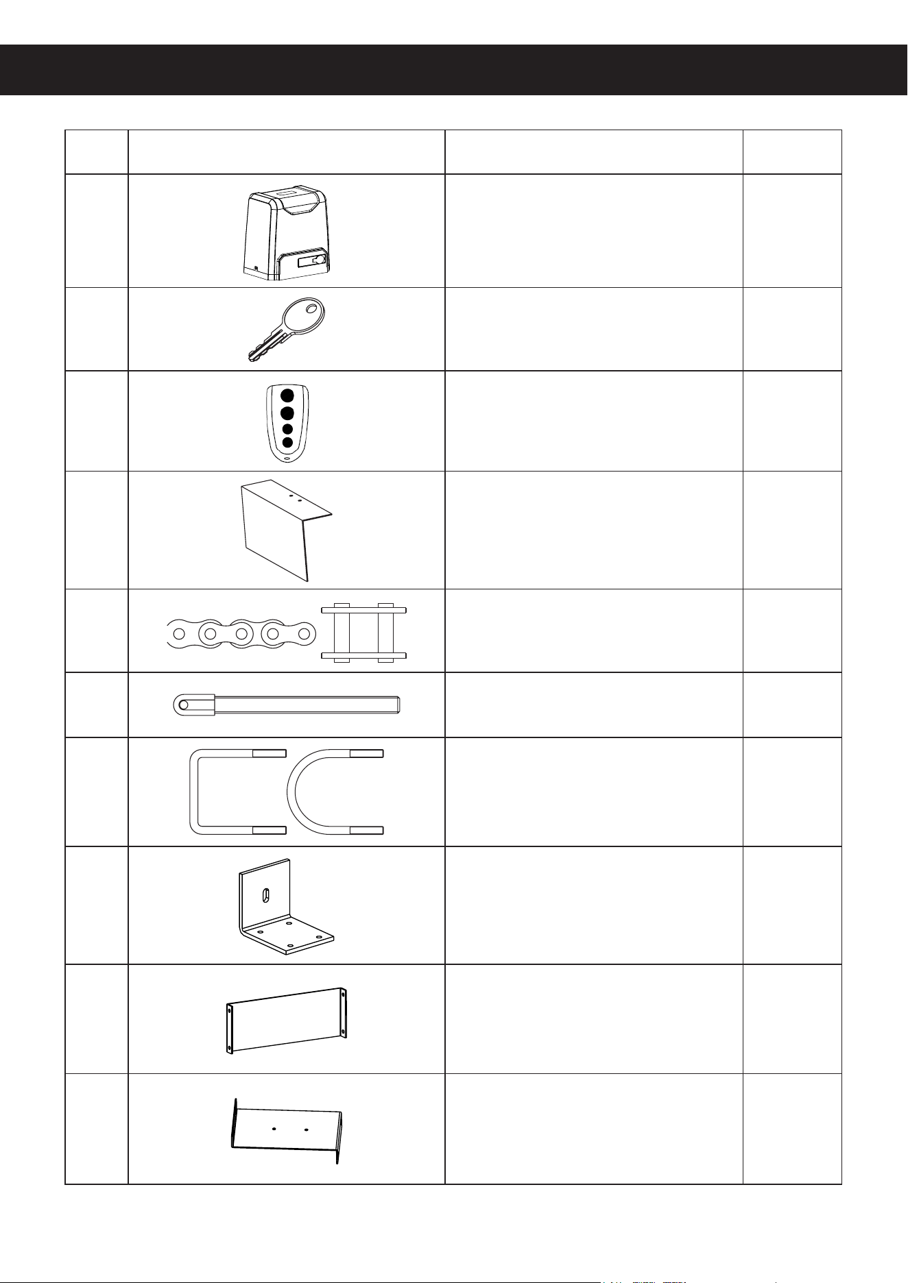
3
No. Picture Name Quantity
A Motor 1
B Manual Release Keys 2
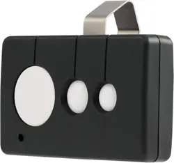
C Remote Controls 2
D Sprocket Cover 1
E #41 Chains 2
F Tie Rods 2
G Square & Round Bolts 8
H Gate Brackets 2
I Horizontal Mounting Plates 2
J Vertical Mounting Plates 2
Package List

4
No. Picture Name Quantity
K M10 Foundation Bolts 4
L Magnet & Bracket Sets 2
M M4×10 Bolts 4
N M6×20 Bolts 8
O M6×65 Hex Bolts 4
P M10×50 Hex Bolts 4
Q M6 Hex Nuts 20
R M8 Hex Nuts 8
S M10 Hex Nuts 12
T M6 Flat Washers 21
U M8 Flat Washers 7
V M10 Flat Washers 13
W M6 Spring Washers 21
X M8 Spring Washers 7
Y M10 Spring Washers 9
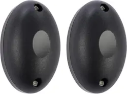
Z Infrared Sensor Set 1
5
Initial Setup
1. Ensure that your gate does not exceed your model's weight capacity and includes the following
features or their equivalent.
2. Ensure that your gate does not exceed 40 feet (12 m) in length. If it exceeds 20 feet (6 m) in
length, you will need to purchase additional ANSI #41 chain and connect it to those provided
with your device.
NEVER use incompatible chain sizes with this device and ALWAYS ensure the gate chain
is securely fastened prior to use.
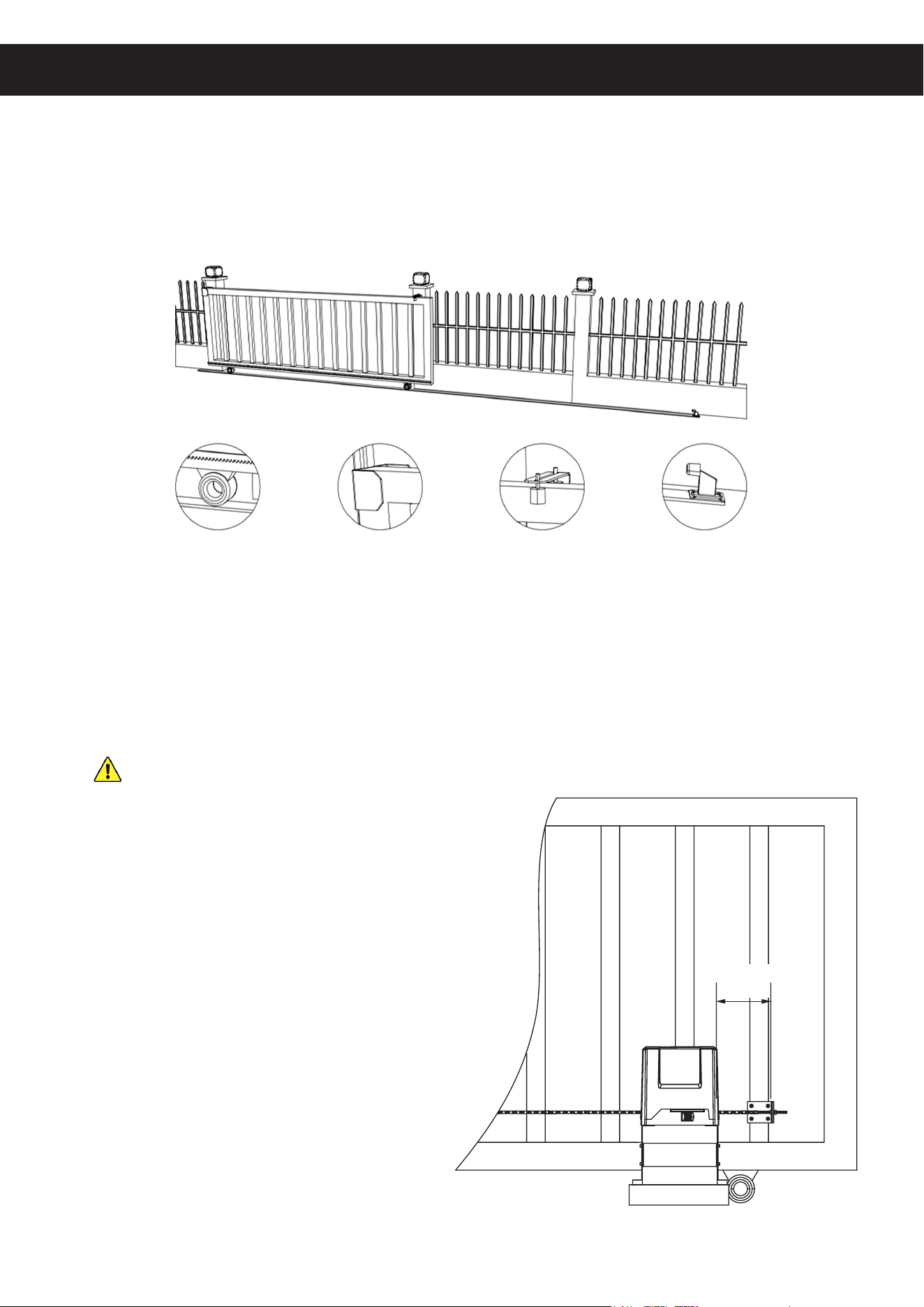
3. Ensure that your gate is properly installed on
rm level ground. It should move smoothly
and horizontally along its entire range and its
wheels and guides should rotate easily and be
free of any corrosion, dirt, or grime. Any track
should be cleaned and rmly mounted along
its entire length. There should be adequate
space at either end to avoid any pinching
or crushing hazard once its movement is
automated or the hazardous area should be
blocked o and warnings posted.
Installation
Figure 1
Track and Wheels End Catch Guide Rollers End Stop
Figure 2
≥ 1 ft.
≥ 30 cm
6
4. Ensure that the gate opener will have a suitable location on rm level ground at least one foot
(30 cm) inside the chain bracket on the nearest end of the gate.
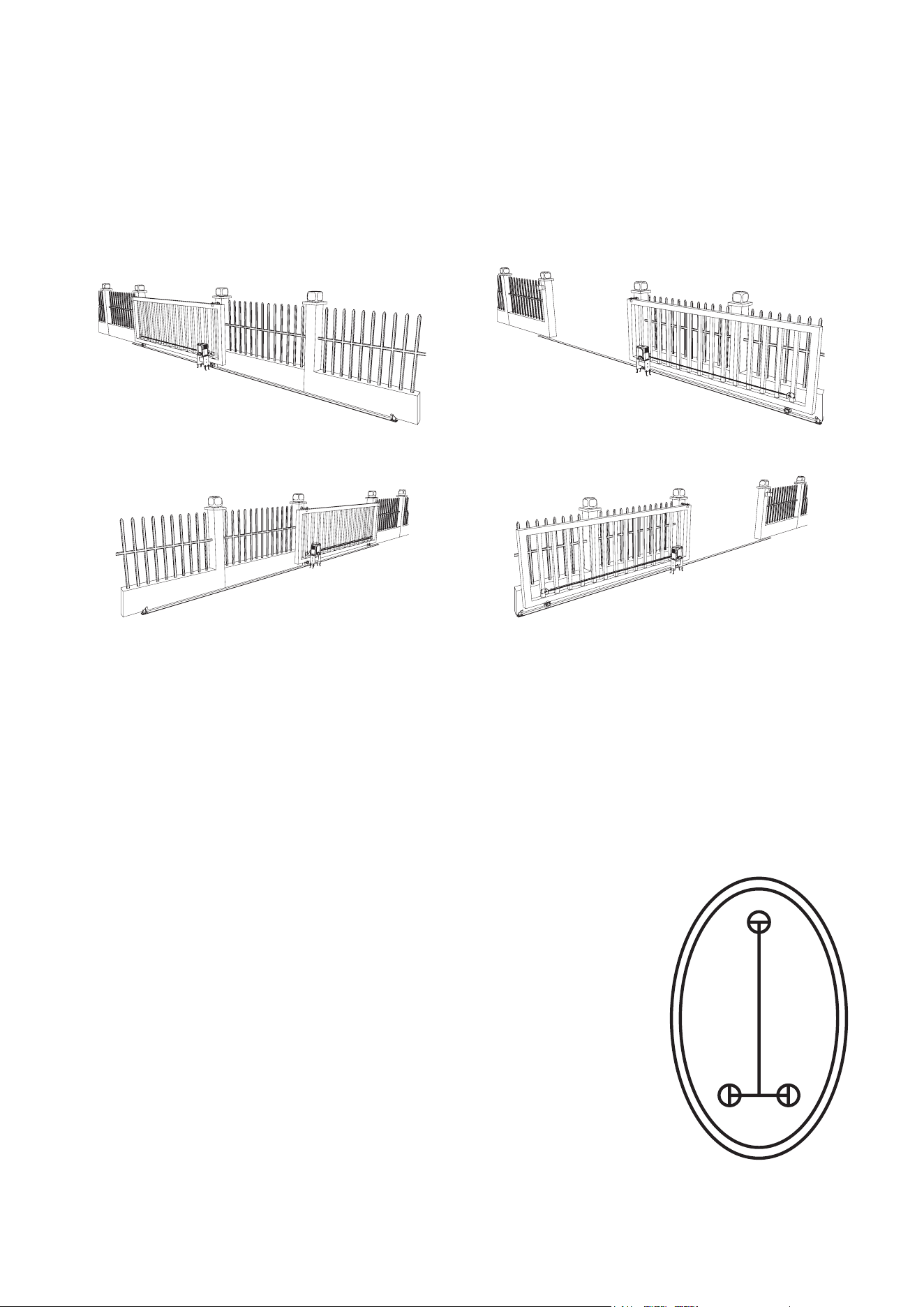
The default settings for this motor are for placement on the right side of your gate when facing
out from your property. It can be installed on the left side but some settings will need to be
reversed for some functions like automatic closure to work properly.
5. Prepare a 110V/60Hz power connection for the gate opener. The wiring should be a 3-core
cable at least 16 AWG (1.5 mm²) thick.
The wiring should run from a GFCI outlet or a circuit breaker within sight of the gate. It is
recommended this outlet or switch be located at least 5 feet (1.5 m) above the ground. The
wiring connections should be able to withstand rain and other weather. It is recommended that
the power cable run underground near the gate inside PVC pipe.
6. If you will use the infrared sensors, prepare locations for them on
opposite sides of your gate. They should be directly across from one
another at least 6′7″ (2 m) apart and no further apart than 65 feet
(20 m). It is recommended that they be placed out of direct sunlight
if possible. Pilot holes for their support bolts (not incl.) should be
placed as shown in Figure 4.
They will need a connection to 12V DC power. This can be provided
from the motor's circuit board or separately. The signal line from the
receiver—the sensor with a 5-pin terminal—and any power lines
should be prepared. The wires should be at least 22 AWG (0.5
mm²) thick. It is recommended that these lines and those from any
other control or access system also be placed underground inside
a separate PVC pipe than the one used for the motor's power cord.
Again, all wiring connections should be able to withstand rain and
inclement weather.
1.77 in.
4.5 cm
0.79 in.
2 cm
Figure 4
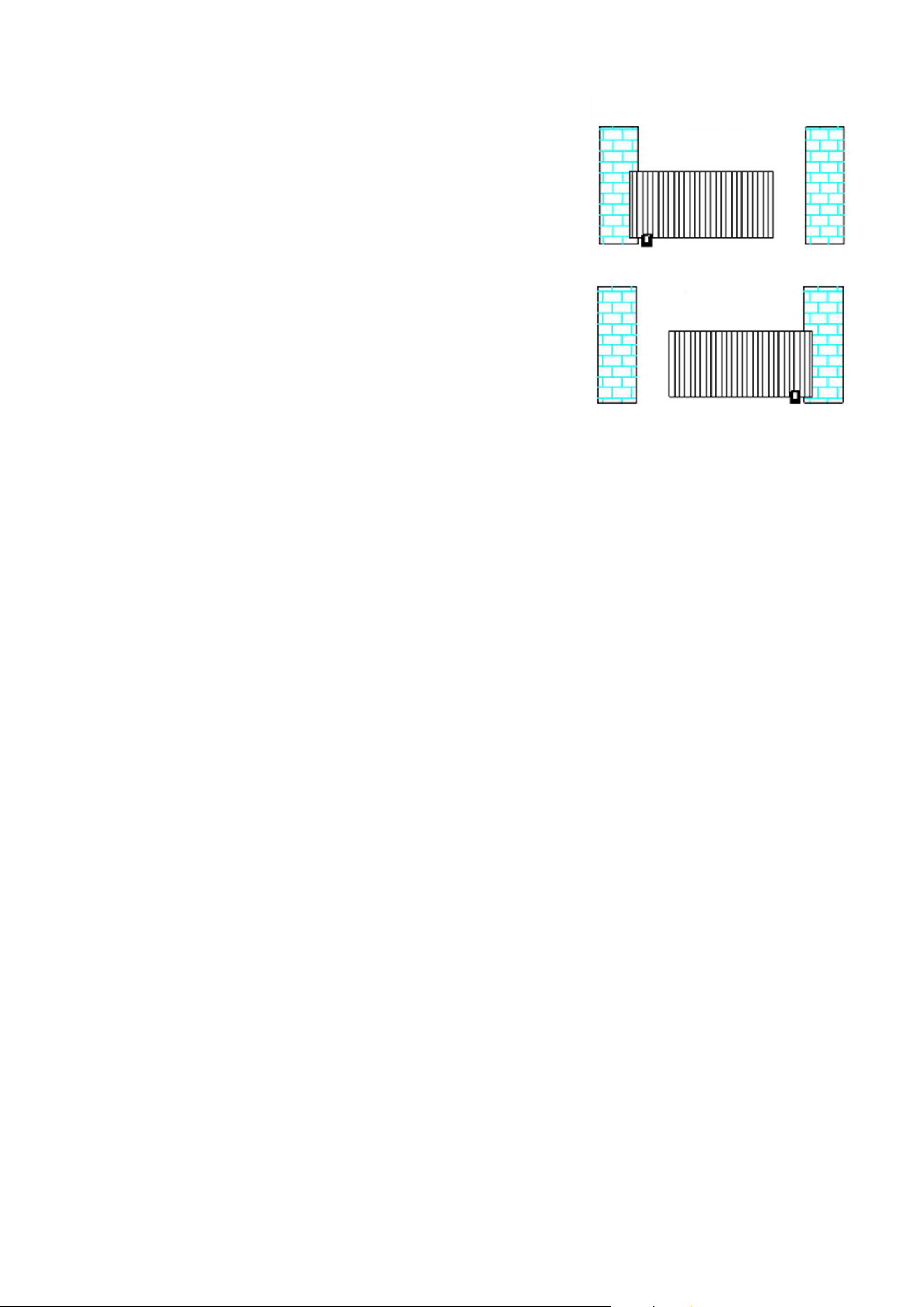
Figure 3
Standard Right Side Installation
Closed
Closed
Open
Open
Optional Left Side Installation
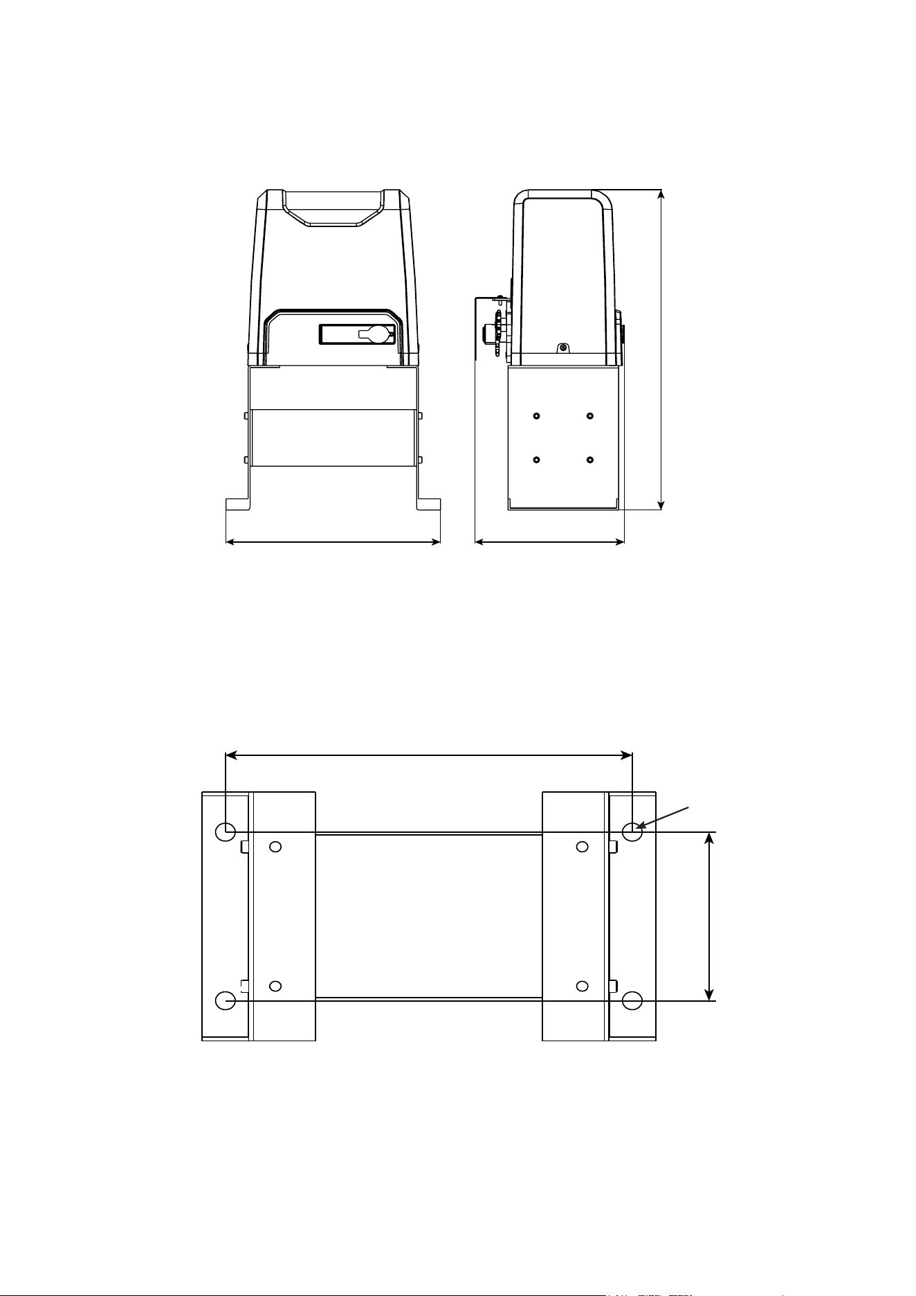
7
Gate Opener Dimensions
Figure 5
Mounting Plate Dimensions
Figure 6
Ø0.59 in. (15 mm)
20.1 in. (51 cm)
13.4 in. (34 cm) 9.33 in. (23.7 cm)
5.47 in. (13.9 cm)
12 in. (30.5 cm)
8
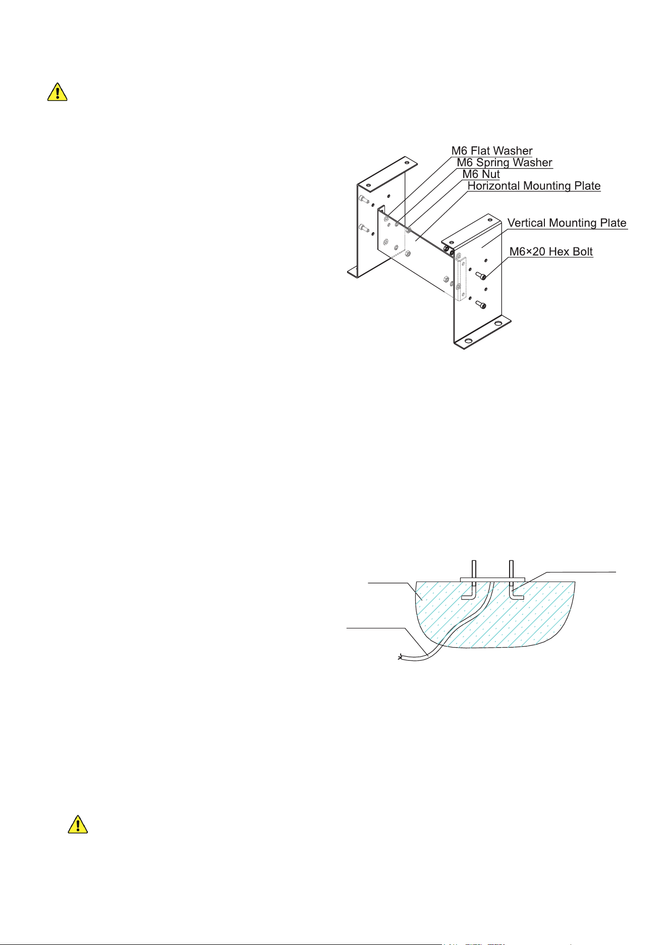
1. Use the two horizontal mounting plates (I) to
brace the two vertical mounting plates (J) as
shown. Use the M6×20 bolts (N), spring (W)
and at washers (T), and nuts (Q) to connect
the plates so that both vertical plates face
inwards on top and the large holes for the
foundation bolts face out.
2. If the area beside your gate already has
concrete 10 inches (25 cm) or deeper, you
can attempt to secure this base into it with
your drill and suitable fasteners.
If not, dig a hole about 2 feet across, 1½ feet
wide, and 10 inches deep (50×40×25 cm) in
the location you have selected for your gate
opener. This hole should be located so the
motor will be at least one foot (30 cm) inside
where the nearest chain bracket will be
attached to the gate.
Base Installation
Your motor MUST be rmly secured for safe use. Do not attempt to use it loose or only
secured to thin pavement.
3. Prepare a form box with the same dimensions and t it into the hole. Nonstick spray can be
used to minimize moisture absorption and ease its future removal.
4. Fill the form with concrete. You will need a minimum of 1.5 cubic feet (40 L) of concrete,
equivalent to about four standard 60 lb. or three standard 80 lb. bags.
A metal wire or cage frame can be added near the sides to further reinforce your concrete
foundation.
5. While the concrete is still wet, adjust the cables’
PVC pipes as needed and insert the four M10
foundation bolts (K) as shown. Remember to
allow for the additional 2 inches (5 cm) or so
that the chain gears will need between the
nearest foundation bolts and the gate.
It is recommended to coat the bolts with a
protective solution to minimize corrosion during
their time in the wet concrete and afterward.
6. Level the upper surface of the concrete.
7. Wait at least 24 hours for the concrete to set, protecting the area from any rain or other weather
as needed.
8. Remove the form box from around the concrete and pack the soil tightly back into place. Adjust
the concrete and surrounding dirt as needed to ensure it is snuggly t, rmly positioned, and
completely level.
If you ever subsequently notice the gate opener rocking with the concrete during use, add
additional concrete or further secure the base as needed.
9. Fix the base onto the foundation bolts using the M10 spring (Y) and at washers (V) and nuts
(S). Use additional washers as needed to keep the base completely level.
Figure 8
Foundation Bolt
Concrete
Power Line
Figure 7
9
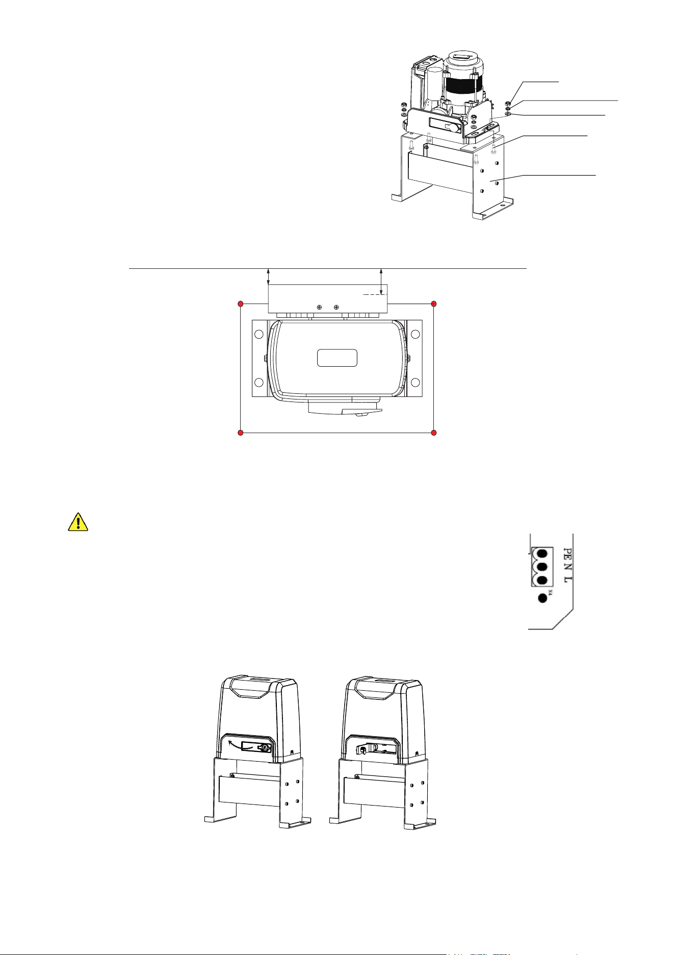
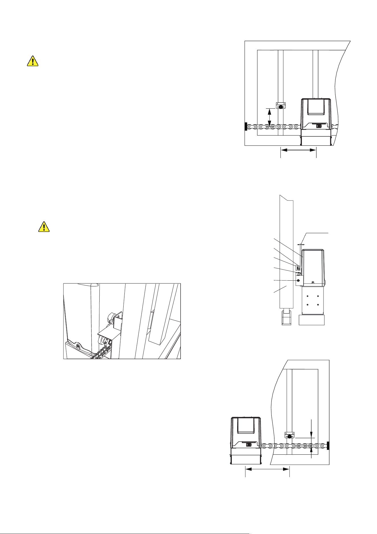
Motor Installation
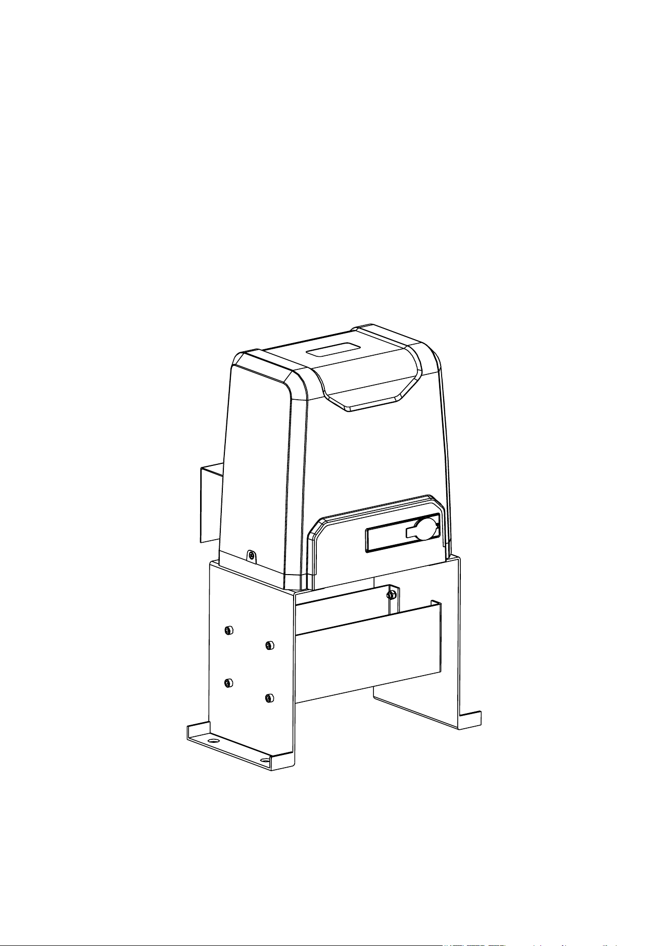
1. Remove the plastic casing from the motor (A).
2. Connect the motor to the base using the M10 bolts
(P) with their spring (Y) and at washers (V) and
nuts (S).
Adjust the placement of the bolts in their slots to
match the expected path of the chain as shown.
Normally, the path of the chain will be 1¼ to 1½
inches (32–39 mm) from the inner edge of the gate.
3. Remove the protective cover from the motor circuit board. Keep its fasteners nearby.
NEVER make electrical connections while the motor’s power supply is active. Disconnect
the GFCI or circuit breaker before any wiring adjustment.
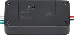
4. Connect your 3-core wiring to the main power terminal on the motor’s
circuit board. Connect the live wire to the L pin, the return or neutral line to
the N pin, and the ground line to the PE pin.
5. Insert a manual release key (B) and open the release bar 90° to put the
motor into manual mode. Check that its cogs rotate freely by hand.
Figure 12
Figure 10
0.67–0.82 in.
(17–21 mm)
1.25–1.54 in.
(32–39 mm)
Figure 9
M10 Flat Washer
M10 Nut
M10 Spring Washer
M10×50 Bolt
Mounting Base
Ground
Neutral
Live
Figure 11
10
Chain Installation
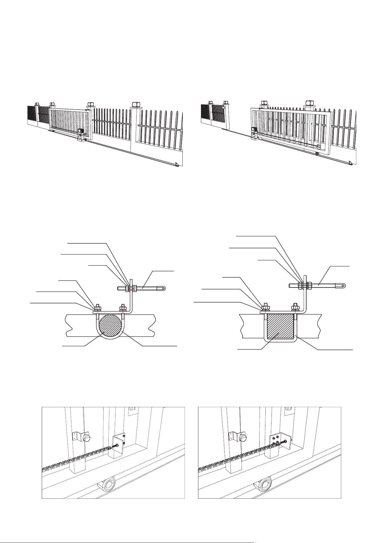
1. Close the gate.
2. Install the gate brackets (H) at or near each end of your gate. They should face in towards your
property and be located at the same height as the two smaller sprockets on the motor. The
nearest bracket should be at least one foot (30 cm) away from the motor.
Use the square bolts (G) for gates with square posts and the round bolts (G) for gates with
round posts.
It is recommended to position the brace for the tie rod (F) on the side of the post nearer to the
motor, but it can be used in either position if necessary.
Figure 13
Figure 14
Figure 15
M8 Flat Washer
M8 Flat Washer
Tie Rod
Tie Rod
Square Bolt
Round BoltGate Post
Gate Post
M6 Flat Washer
M6 Flat Washer
M8 Spring Washer
M8 Spring Washer
M6 Spring Washer
M6 Spring Washer
M8 Nut
M8 Nut
M6 Nut
M6 Nut
11
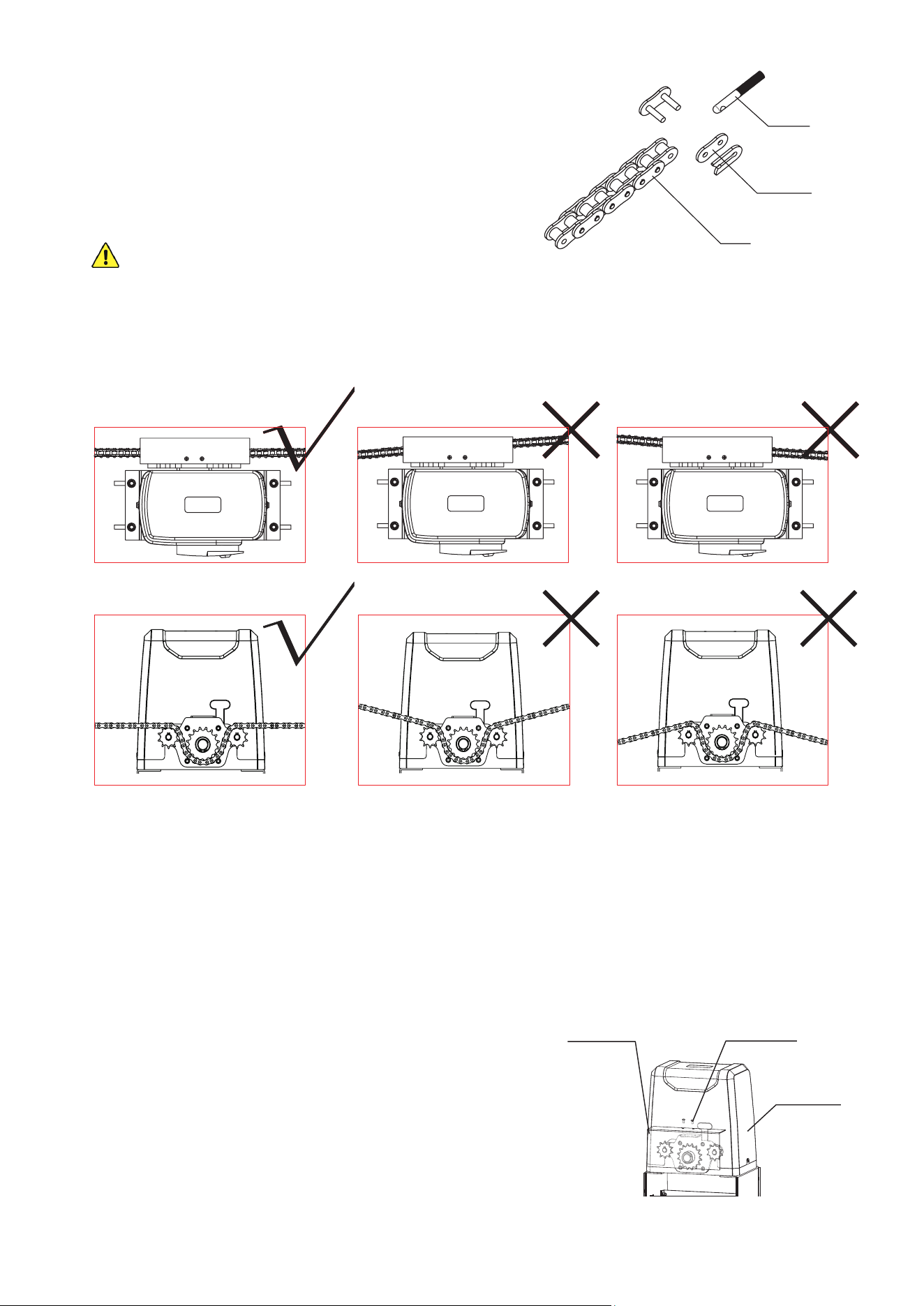
3. Fasten one of the chains (E) to the tie rod of the
bracket farther from the motor by opening, positioning,
and resealing its nal chain link.
If necessary, repeat the process to connect the two
chains to one another or even to add additional lengths
of chain.
ONLY use ANSI #41 chain with this device and do
not use any chain longer than 40 feet (12 m).
4. Adjust the length of your chain so that it will be roughly
taut—neither loose nor tight—once threaded through the motor and attached to the other
bracket. Conrm that the chain will run straight from one bracket to the other without requiring
the sprockets to support any of the gate's weight.
Adjust the positions of the brackets as necessary but do not position either bracket closer than
one foot (30 cm) to the motor.
5. Activate your motor’s main power connection. Press the TEST button on its circuit board or
press any button on either remote control (C). The sprockets should begin to turn. Conrm
that they will pull your chain in the correct direction. Press TEST or your remote’s button again
to stop the sprockets and disconnect the motor from power. (If the wheels spin in the wrong
direction for their location, see how to reverse their direction below.)
6. Thread the chain through the motor’s sprockets as
shown. Adjust the position of the motor on its base
if needed by loosening, moving, and retightening its
M10 bolts.
7. Connect the chain to the tie rod on the second bracket.
8. After nishing adjustment and testing (see below),
attach the motor’s cover and the sprocket cover (D)
using their M4 bolts as shown.
Figure 16
Tie Rod
Chain Link
Chain
Figure 18
M4×10 Bolts
Sprocket Cover
Motor Cover
Figure 17
12
Magnetic Limit Installation
Using this gate opener without its magnets in the
correct position risks damage to the motor and to
the gate, including possible derailment.
1. Place the motor in manual mode. Move the gate to
the position you want it to go to when fully open.
2. Find the post on the open gate about 6–8 inches
(15–20 cm) farther away from your driveway than the
middle of the motor.
3. Find the position on that post exactly 3.98 inches
(10.1 cm) above the middle of the taut chain.
4. Place one of the magnets (L) there using its bracket
and M6×65 bolts (O), spring (W) and at washers
(T), and nuts (Q) or using any similarly secure
equipment. The magnet should be held facing the
opener with at least 0.4 inches (1 cm) between it and
the motor casing.
The magnets and brackets are interchangeable
but the functions of their positions are not.
This higher magnet will function as the OPEN limit
switch because of the position of the sensors in
the motor housing. Reverse the diagrams shown in
Figures 19 and 21 for left side installation.
5. Move the gate to the position you want it to lock at
when fully closed.
6. Find the post on the closed gate about 6–8 inches
(15–20 cm) towards the driveway from the center of
your motor.
7. Find the position on that post exactly 1.53 inches
(3.9 cm) above the middle of the taut chain.
8. Place the other magnet there using its bracket and
fasteners or other similarly secure equipment as
before.
9. Fine tune the positions of the magnets during initial
testing (see below) so the system gently stops your
gate at the best location.
Figure 19
Figure 20
Figure 21
Motor
Magnet
Magnet Bracket
Chain
Sprockets
Gate
≤ 0.8 in. (20 mm)
6–8 in. (15–20 cm)
1.53 in. (3.9 cm)
3.98 in. (10.1 cm)
6–8 in. (15–20 cm)
13
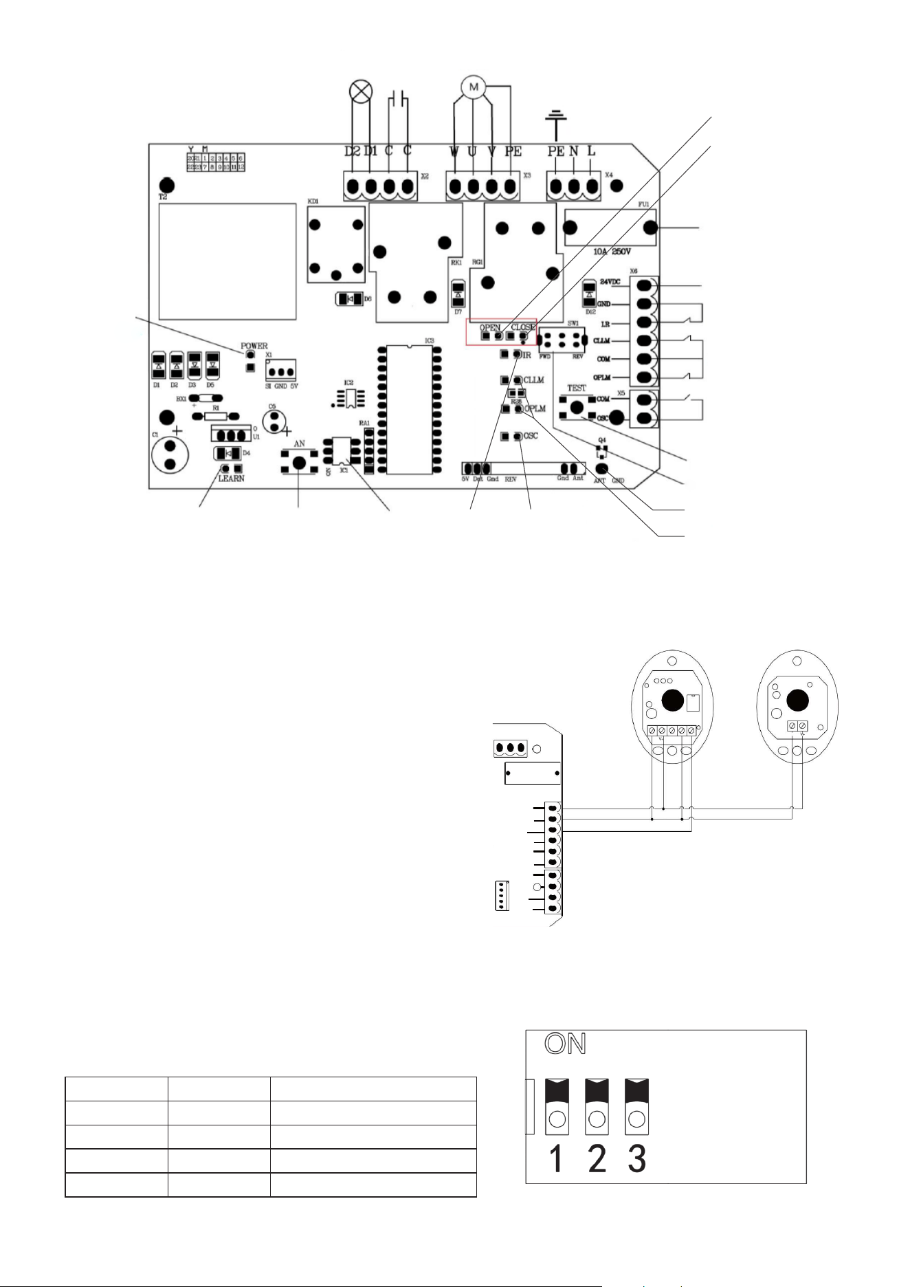
Voltage
Transformer
Lamp
Capacitor Motor
Main Power
Ground
10A Fuse
Infrared Sensor
Limit Switches
External Button
Connection
Test Button
Direction Switch
Antenna
Test
Indicator
Power
Indicator
Remote Signal
Indicator
IR
Indicator
Open Indicator
Close Indicator
Limit Indicators
Remote Pair
Button
DIP Switches
24V DC
Optional Infrared Sensor Installation
1. Remove the small wire from the motor’s circuit
board that connects the IR and GND pins in its
infrared sensor terminal.
2. Connect the sensors’ wiring to the control board
according to Figure 23. The sensors’ V+ pins
should be connected to the 24V pin on the board;
their V- pins and the receiver’s COM pin should all
be connected to the GND pin; and the receiver’s
NC pin should be connected to the IR pin.
3. Install the infrared sensor set (Z) near your gate at
the positions prepared for them. If possible, cover
or otherwise protect them from direct sunlight.
Setting Automatic Closure
To set the gate to automatically close after a
predetermined length of time, toggle the middle and
right DIP switches on its circuit board.
Figure 23
PE
10A 250V
NL
×1
×5
×8
X
7
24VDC
GND
I.R
CLLM
COM
COM
STP
CLS
OPN
OPLM
V- COMN CNO
s J
Receiver Transmitter
DIP2 DIP3 Eect
UP UP Manual Closure
UP DOWN 15 Second Delay
DOWN UP 30 Second Delay
DOWN DOWN 45 Second Delay
Figure 24
Figure 22
14
Initial Testing
1. If the motor is located on the right side of your gate, the
direction switch on its circuit board should be toggled to
Forward (FWD). If it is located on the left side, toggle the
switch to Reverse (REV).
2. Clear any obstacles from the gate’s path and keep all
bystanders away.
3. Activate the power to your motor. The POWER and IR
indicator lights should come on.
4. Test the infrared sensors by blocking the path between
the two sensors with any obstacle. The IR indicator light
should turn o. Remove the obstacle. The indicator light
should come back on.
5. Press the TEST button. The Test indicator light (OSC)
should come on and the gate should begin to move.
6. While the gate is opening, the OPEN indicator light should come on. When the gate reaches
the open limit switch, the Open Limit indicator light (OPLM) should come on and the gate
should come to a stop.
If the limit switch is so close that it contacts the motor housing or is so distant that it fails to
activate the motor's sensor, adjust its support bracket or the motor's placement on its base as
needed to correct the problem. If the limit switch stops the gate too early or too late, adjust the
location of the magnet's support bracket so that the gate will gently stop in the correct place.
7. While the gate is closing, the CLOSE indicator light should come on. When the gate reaches
the close limit switch, the Close Limit indicator light (CLLM) should come on and the gate
should come to a stop. Again, adjust the magnet's support bracket as needed.
8. The top button on your two remote controls (C) should already be paired with your motor.
They use a single control mode at a distance of up to 98 feet (30 m). Pressing either button
should cycle through the commands OPEN→STOP→CLOSE→STOP. The remote indicator
light (LEARN) should come on each time a signal is received.
Test both remotes through the full cycle of commands. Test that the open and close limit
switches function properly while the motor is being controlled by the remotes. If you have
chosen to use the automatic close function, you can test that it works correctly at the same time.
Open the gate, wait the set amount of time, and see if the gate begins closing automatically.
9. Deactivate the power to your motor using its circuit breaker. If any abnormalities have been
detected during testing, make the necessary adjustments—e.g. by repositioning the infrared
sensors or magnetic limit switches—or contact Customer Service for help.
10. Replace the circuit board, motor, and sprocket covers and their fasteners.
Figure 25
Left-Mounted
Right-Mounted

15
• Always supervise children and pets near the gate, the motor, and their controls to prevent
accidents.
• Always fully disconnect your motor from its power supply before removing its cover or making
any adjustments to its wiring. Use trained technicians for rewiring or repair work.
• Keep your chain and track clean and free of any corrosion, grime, or obstructions.
• Lubricate wheels and rollers as needed.
• If your gate is not in regular use, test it at least once a month. If any problems are noticed during
testing or normal use, disconnect the motor from power, unlock the gate, and test manually
that it still moves smoothly on its own. Tighten, repair or replace problematic parts as needed.
Only use identical components, and always fully replace damaged or malfunctioning electrical
cables.
Maintenance
Remote and Wireless Keypad Pairing
1. Up to 23 additional remote or wireless control buttons can be paired to the
gate’s circuit board. Be sure that they use the 433.92 MHz radio band or can
be congured to do so.
NEVER pair the same button to 2 dierent gates or devices at the same
time.
Disconnect the motor from power, open its covers to expose its circuit board,
and restore power.
2. Press the pairing button (AN). The remote indicator light (LEARN) should come on.
3. Press the button on the remote control to be paired or enter the correct passcode and press
the open button on your wireless control.
4. Press the same button on the remote again or reenter the passcode and press the open button
again on your wireless control. The remote indicator light should ash and go out.
5. The button or keypad is now paired and can be used to open or close the gate. This pairing
should remain stored in memory even when power to the gate opener is cut accidentally or at
the circuit breaker.
6. Test that the gate responds correctly to commands from the new remote button or keypad.
When you are nished pairing and testing, replace the motor's covers and fasteners.
For community gates where multiple commands may accidentally be sent at the same time,
it is recommended that DIP1 on the circuit board be set to its UP position. This will cause
the device to only process commands from wireless controls to open; it will not process any
commands to pause or close the gate.
When this mode is used, DIP2 and DIP3 must be set to one of the automatic close options or
the gate will require a remote control or manual assistance to close again.
To erase all stored controls from memory, press and hold the pairing button. The remote
indicator light should come on at rst and then go out as the board’s memory is purged.
Figure 26

16
Potential Problems Possible Solution(s)
The gate does not open
or close normally and no
indicator lights activate on
the circuit board, even when
pressing the TEST button.
Verify that the power supply is functioning properly.
Check that the fuse is not blown.
Have a certied electrician rewire your system.
The door opens but does not
close.
Remove any obstacles which might be in the gate's path.
Conrm that the magnets' placement and the circuit board's
direction switch match your motor's position as discussed
above.
Replace the short wire between the IR and GND pins on the
circuit board's infrared sensor terminal or correct the wiring
for your infrared sensors.
A remote control does not
active the gate.
Change the remote control’s battery.
Pair the remote control to the board again.
Remove any obstruction between the motor and the remote.
The motor makes noise but
the chain and gate do not
move.
Remove any obstruction from the motor, sprockets, chain,
or gate path.
Have a certied electrician test the gate opener’s capacitor,
and replace or rewire it if necessary.
The circuit breaker trips
repeatedly.
Remove any other devices from the circuit providing the
motor’s power and conrm it is not unstable or experiencing
surges.
Have a certied electrician check the power supply line and
motor line for short circuits. Repair if necessary.
The gate suddenly stops or
reverses when moving.
Remove any obstacles which might be in the gate's path.
Check the infrared sensors, their wiring, and the circuit board
indicator lights, adjusting as necessary.
Check the magnets, their placement, and the circuit board
indicator lights, adjusting as necessary.
An obstruction to the IR
sensors stops the gate from
opening but doesn't stop it
from closing.
Correct the direction settings on the circuit board to match
your motor's placement.
Troubleshooting

Contact Us
Thank you for choosing our products! If you have any questions or comments,
contact us at contact@b2csupportpro.com and we'll resolve your issue ASAP!
For a .pdf copy of the latest version of these instructions, use the appropriate
app on your smartphone to scan the QR code to the right.
SGO-2700-00 SGO-3300-00
Rev. 10 Jan. 2023
Disposal
Electrical products should not be disposed of with household products. In the
EU and UK, according to the European Directive 2012/19/EU for the disposal
of electrical and electronic equipment and its implementation in national laws,
used electrical products must be collected separately and disposed of at the
collection points provided for this purpose. Locations in Australia, Canada,
and the United States may have similar regulations. Contact your local
authorities or dealer for disposal and recycling advice.