V20221227
Infrared Sensor Set
Instructions
• The instructions provided herein are only for general information. ALWAYS install the sensors
in full compliance with your gate’s user manual.
• Keep children and pets away from the sensor and the gate when they are in use.
• ALWAYS make sure the sensor is properly aligned with the gate, as misalignment can cause
the gate to malfunction or become stuck.
• ALWAYS keep the sensors and areas around them clean and free of debris. Dust, dirt, and
other obstructions can interfere with the sensor's operation. Install away from direct sunlight.
• Maintain this product. Check for misalignment, binding, wear, or other damage before use. If
any damage is detected, repair or replace the problematic components before further use.
Warning!
Safety Information
Specications
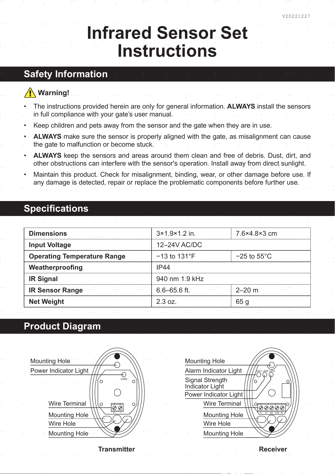
Product Diagram
Dimensions
3×1.9×1.2 in. 7.6×4.8×3 cm
Input Voltage
12–24V AC/DC
Operating Temperature Range
−13 to 131°F −25 to 55°C
Weatherproong
IP44
IR Signal
940 nm 1.9 kHz
IR Sensor Range
6.6–65.6 ft. 2–20 m
Net Weight
2.3 oz. 65 g
Mounting Hole Mounting Hole
Power Indicator Light
Power Indicator Light
Signal Strength
Indicator Light
Alarm Indicator Light
Wire Terminal Wire Terminal
Mounting Hole Mounting Hole
Wire Hole Wire Hole
Mounting Hole Mounting Hole
Transmitter Receiver
Thank you for choosing our products! If you have any questions or comments,
contact us at help@cs-supportpro.com and we'll resolve your issue ASAP!
For a .pdf copy of the latest version of these instructions, use the appropriate
app on your smartphone to scan the QR code to the right.
AGO-YH00-0Z Rev. 27 Dec. 2022
Contact Us
Installation
Maintenance
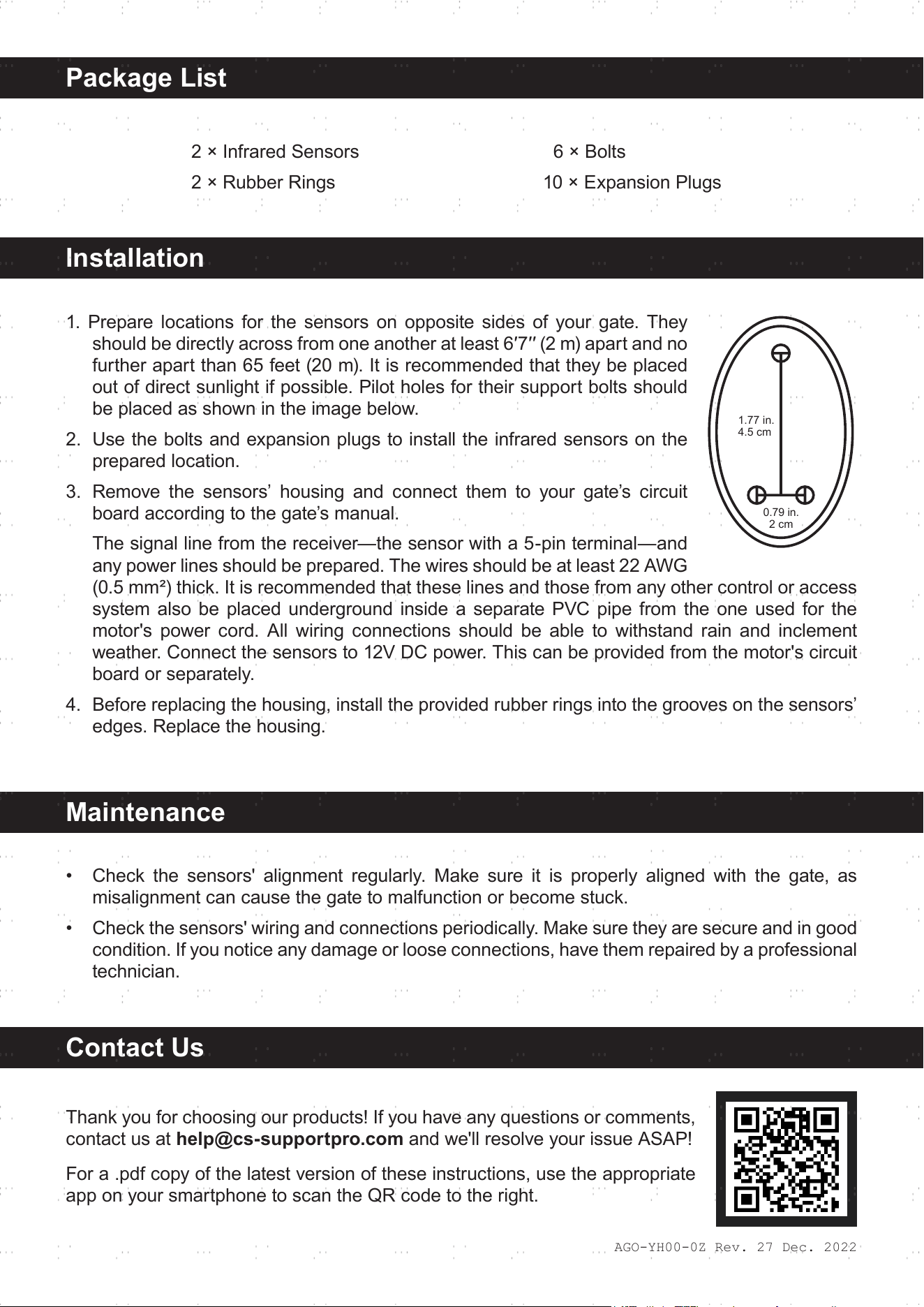
1. Prepare locations for the sensors on opposite sides of your gate. They
should be directly across from one another at least 6′7′′ (2 m) apart and no
further apart than 65 feet (20 m). It is recommended that they be placed
out of direct sunlight if possible. Pilot holes for their support bolts should
be placed as shown in the image below.
2. Use the bolts and expansion plugs to install the infrared sensors on the
prepared location.
3. Remove the sensors’ housing and connect them to your gate’s circuit
board according to the gate’s manual.
The signal line from the receiver—the sensor with a 5-pin terminal—and
any power lines should be prepared. The wires should be at least 22 AWG
(0.5 mm²) thick. It is recommended that these lines and those from any other control or access
system also be placed underground inside a separate PVC pipe from the one used for the
motor's power cord. All wiring connections should be able to withstand rain and inclement
weather. Connect the sensors to 12V DC power. This can be provided from the motor's circuit
board or separately.
4. Before replacing the housing, install the provided rubber rings into the grooves on the sensors’
edges. Replace the housing.
• Check the sensors' alignment regularly. Make sure it is properly aligned with the gate, as
misalignment can cause the gate to malfunction or become stuck.
• Check the sensors' wiring and connections periodically. Make sure they are secure and in good
condition. If you notice any damage or loose connections, have them repaired by a professional
technician.
1.77 in.
4.5 cm
0.79 in.
2 cm
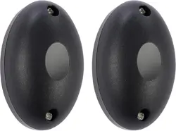
2 × Infrared Sensors
2 × Rubber Rings
6 × Bolts
10 × Expansion Plugs
Package List