Sliding Gate Opener
User Manual
1400LBS / 600KG
V20221135

1
Dear users,
Thank you for choosing this product. Please read the manual carefully before assembling and
using it. Please do not leave out the manual if you send this product to a third party.
Safety Instruction
Please ensure that the using power voltage matches with the supply voltage of gate
opener (AC110V ); kids are forbidden to touch the control devices or the
remote-control unit.
The remote-control unit is controlled by a single button mode. The indicator light on
the remote-control unit will flicker when the button on it is pressed. Main engine and
gate can be unlocked by disengagement wrench and the gate can move with manual
operation after disengagement.
Please ensure that no one is around the main engine or gate when the switch is
operated and it is usually demanded to examine the stability of installation. Please
temporarily stop using if the main engine needs repairing or regulation.
The installation and maintenance of the products must be carried out by
professionals.
2
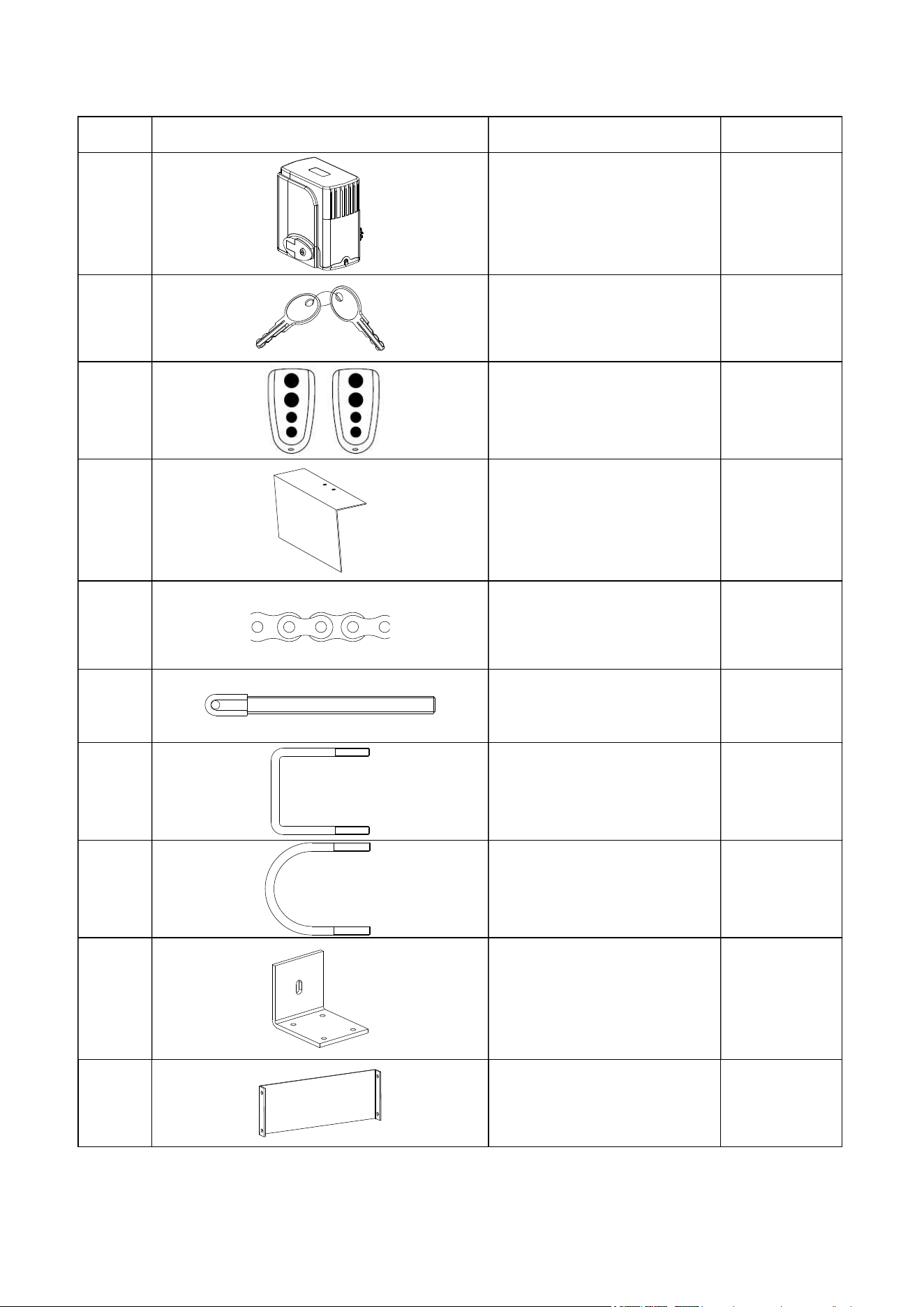
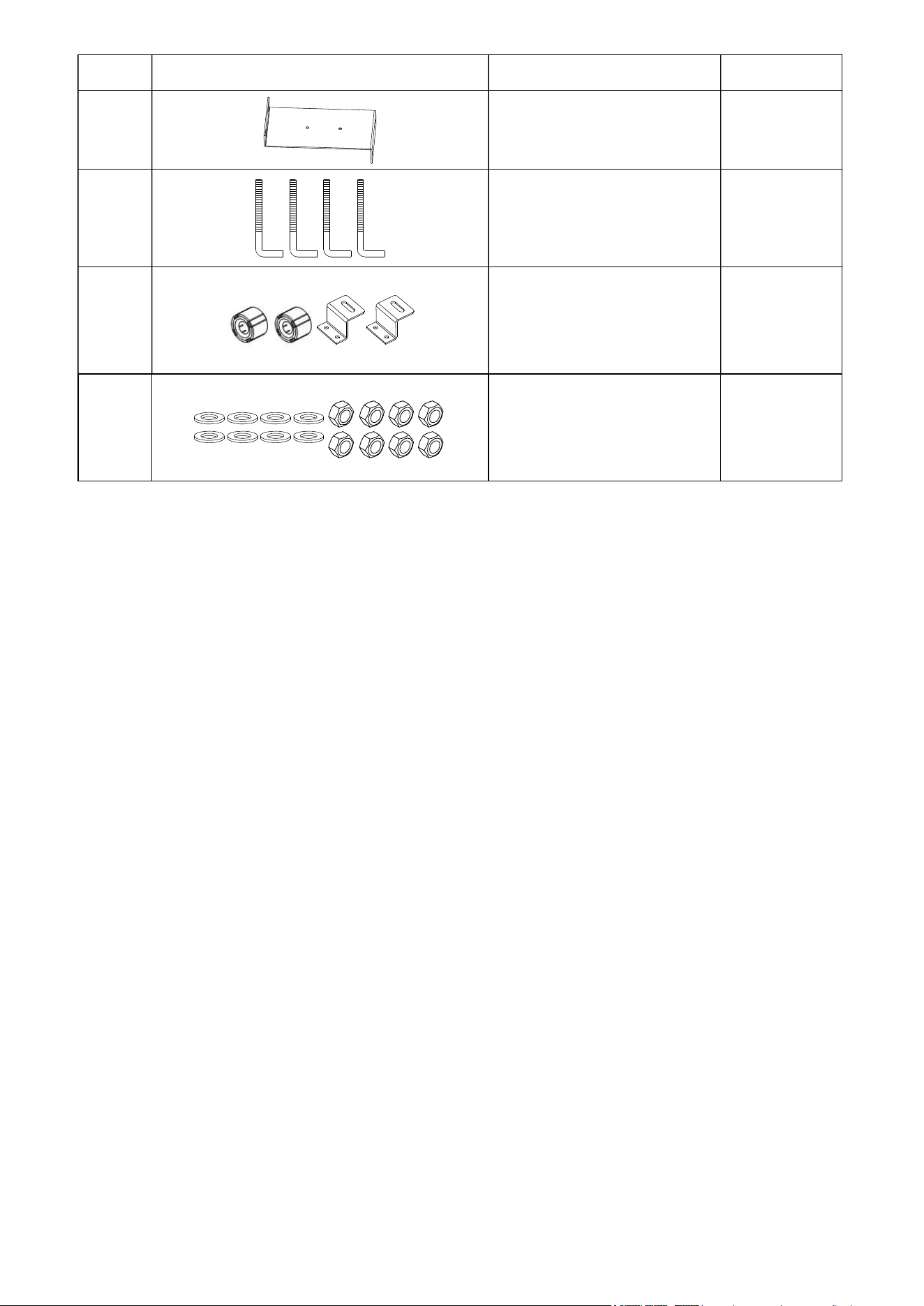
Packing List
No. Picture Name Quantity
1 Main engine 1
2 Manual release key 2
3 Remote control 2
4 Sprocket cover 1
5 Chain 19.68ft
6 Tie rod 2
7 Square screw 4
8 Round screw 4
9 Door connecting plate 2
10 Horizontal mounting plate 1
3
No. Picture Name Quantity
11 Vertical mounting plate 2
12 Foundation bolt M8 4
13 Magnets & block 1
14 Washer & Nuts 1 bag
4
Technical parameters
This sliding gate opener is applicable to gate weight less than 600kg (1400Lbs), and length of the sliding
gate should be less than 30ft. This gate opener must be installed inside the enclosure or yard for protection.
Maximum weight of gate 600KG (1400Lbs)
Power supply 110V/60Hz
Motor power 280W
Gate moving speed 40ft/min
Remote control distance ≥ 30m(10ft)
Remote control mode Single button mode
Limit switch Magnetic limit switch
Noise ≤58dB
Working duty S2, 15min
Recording of up remote controls 20
Frequency 433.92 MHz
Working temperature -20°C ~ +70°C
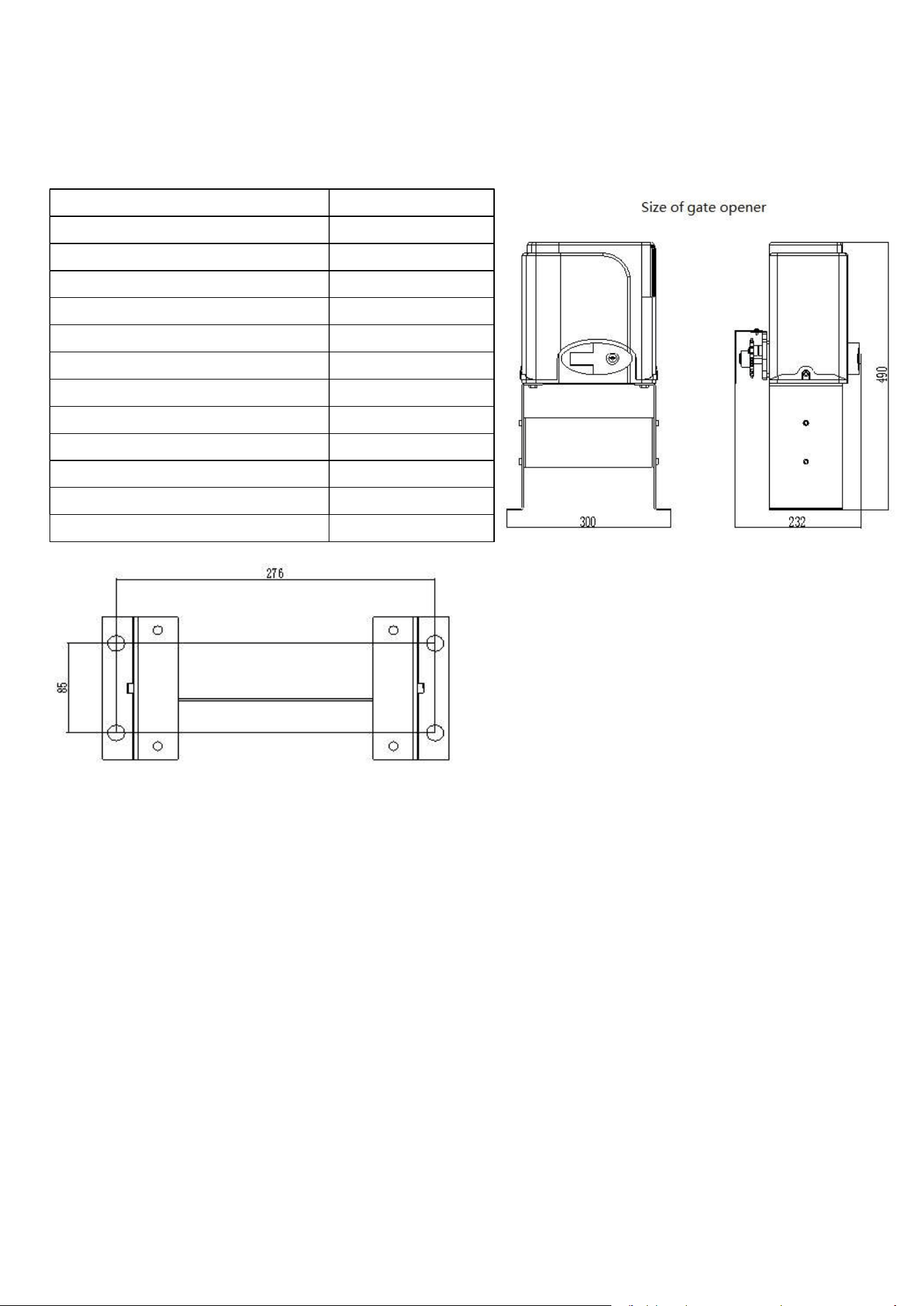
Package weight 34.4Lbs
Size of embedded hole
Installation procedures
Preparation work before installation
Please ensure that the sliding gate is correctly installed, the gate rail is horizontal, and the gate can glide
back and forth smoothly when moved by hands before installing the gate opener.
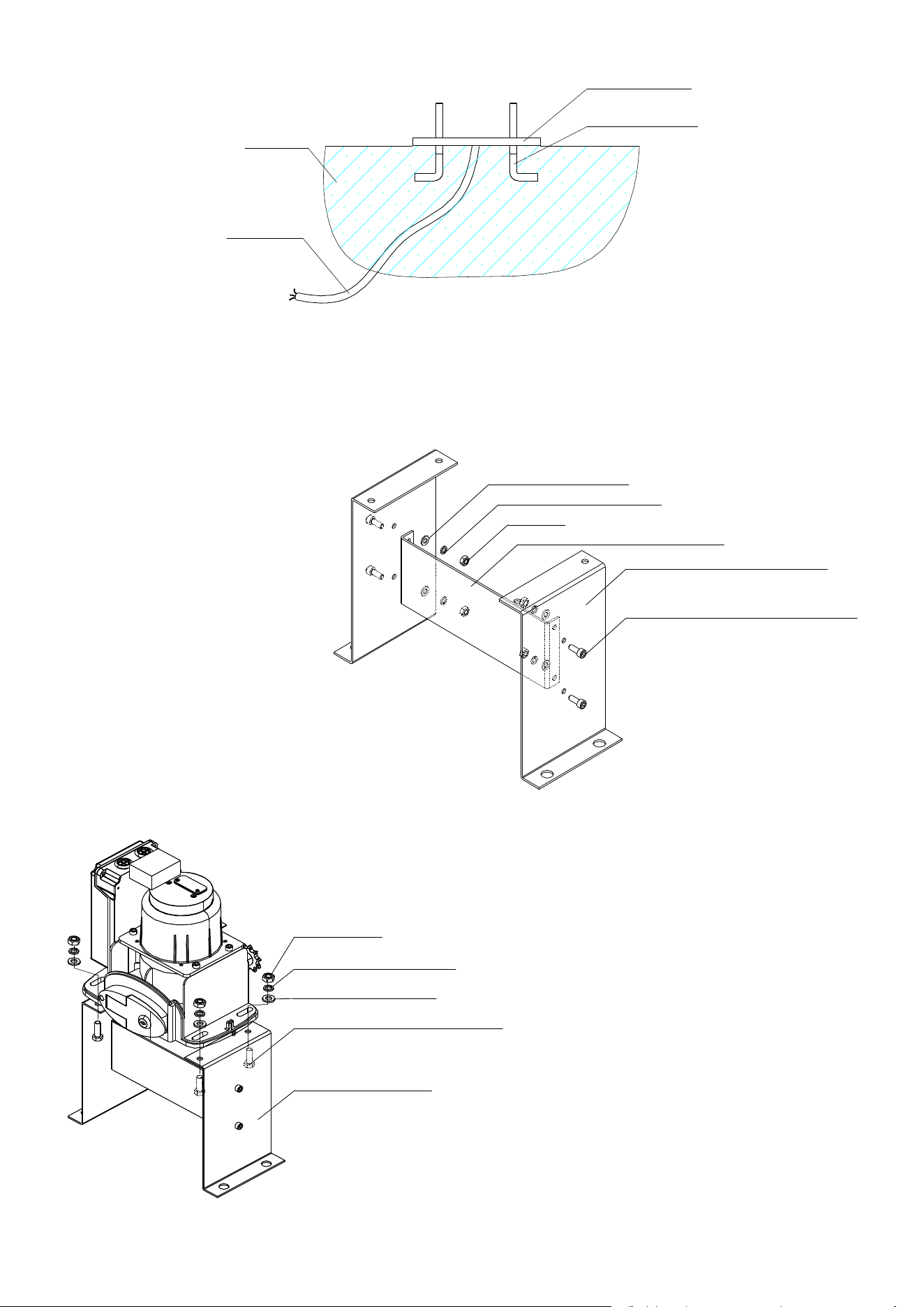
Cable installation
Please bury the motor & power cable and controlling cable with PVC tube, and use two PVC tubes to bury
(motor & power cable) and (controlling cable) separately, so as to guarantee normal operation of the gate
opener and protect the cables from damages.
Concrete pedestal
Please cast a concrete pedestal with the size of 19.69inch x 13.78inch and depth of 7.87inch in advance, so
as to firmly install the gate opener. Please verify whether the distance between the gate and gate
opener is suitable before casting the pedestal.
5
Concrete
Power line
Mounting base
Foundation bolt
Embedded screws
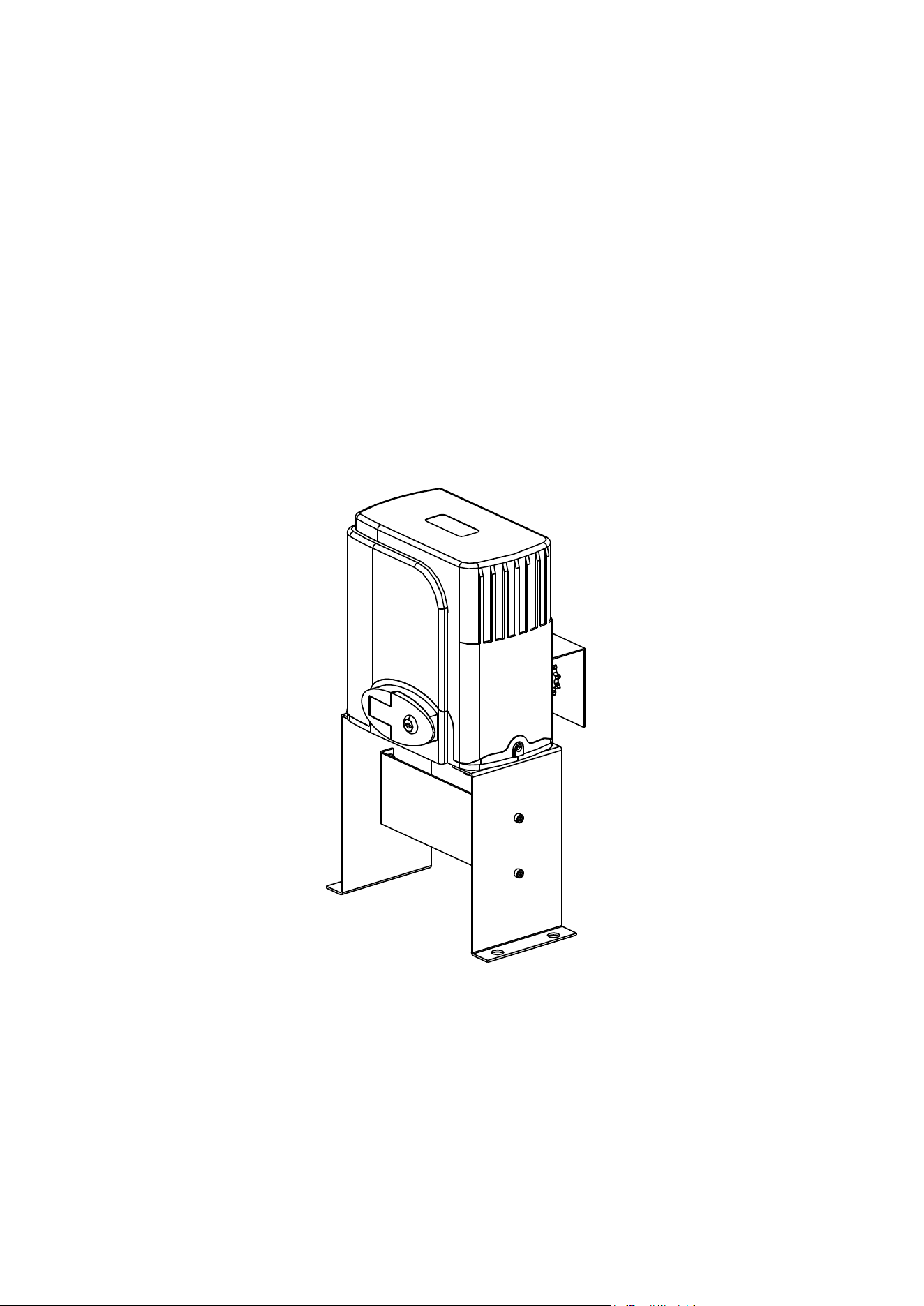
Main engine installation
a) Dismantle the plastic housing on the main engine before installation and keep relevant fasteners properly;
b) assemble the detachable mounting base;
InnerInner hexagonhexagon screwscrew M6×20M6×20
VerticalVertical mountingmounting platenplaten
HorizontalHorizontal mountingmounting plateplate
NutNut M6M6
SpringSpring washerwasher
φ
6
FlatFlat washerwasher
φ
6
c) Assemble the machine engine to the mounting base;
MountingMounting basebase
HexagonHexagon screwscrew M8×25M8×25
FlatFlat washerwasher
φ
8
SpringSpring washerwasher
φ
8
NutNut M8M8
6
d) Please prepare the power line for connecting mounting plate and main engine (the number of power
supply cable core shall not be less than 3 PCS, the sectional area of cable core shall not be lower than
1.5mm² and the length shall be determined by users according to the field situation) due to different
installation environments;
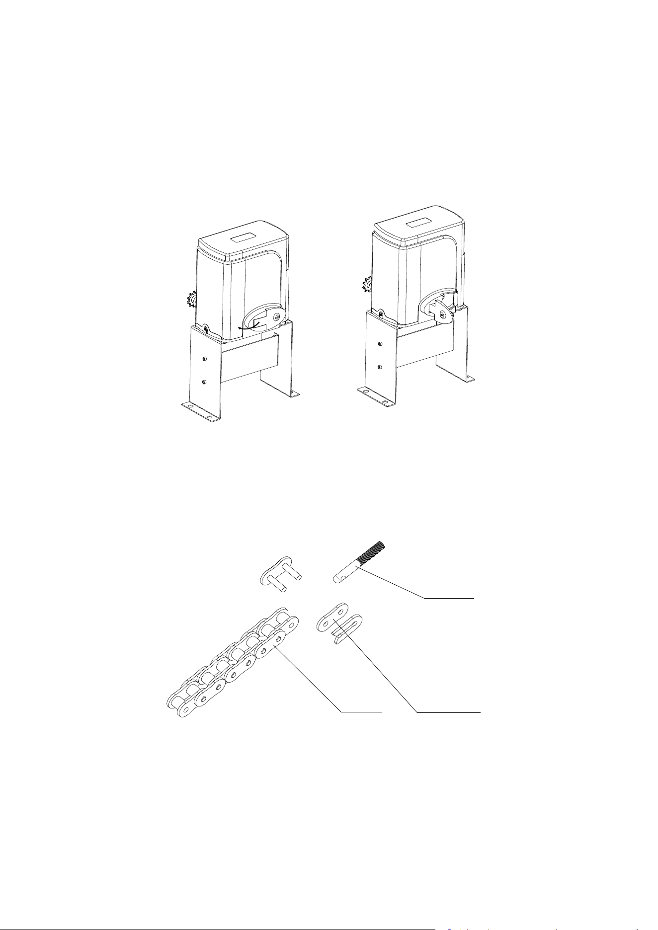
e) Please unlock the main engine before installation, the unlock method is: take out the key cover, insert the
key, and open the manual release bar till it rotates by 90°. Then turn the output sprocket and the sprocket
can be rotated easily;
Turn on 90°
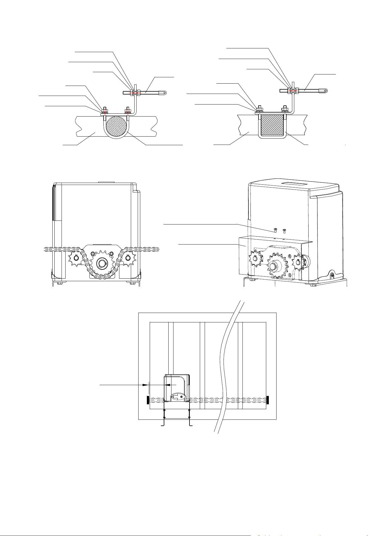
Chain installation
Close the gate; connect the tie rod with chain through chain link; fasten the tie rod to the door connecting
plate by washers and nuts . If necessary, the chain can be shortened. If it need to be lengthened, make sure
to use same type of chain. (US standard NO.41).
ChainChain
ChainChain linklink
TieTie rodrod
7
Use the round screws when the door frame is round; Use the square screws when the door frame is square.
Gate
Round screw
Spring washer
φ
8
Nut M8
Flat washer
φ
8
Tie rod
Nut M6
Spring washer
φ
6
Flat washer
φ
6
Gate
Square screw
Spring washer
φ
8
Nut M8
Flat washer
φ
8
Tie rod
Nut M6
Spring washer
φ
6
Flat washer
φ
6
Install the chain and sprocket cover as shown in the figure.
CrossCross screwscrew M4×10M4×10
SprocketSprocket covercover
The distance between main engine and chain ends should be at least 11.81inch (30cm):
.
≥30CM
8
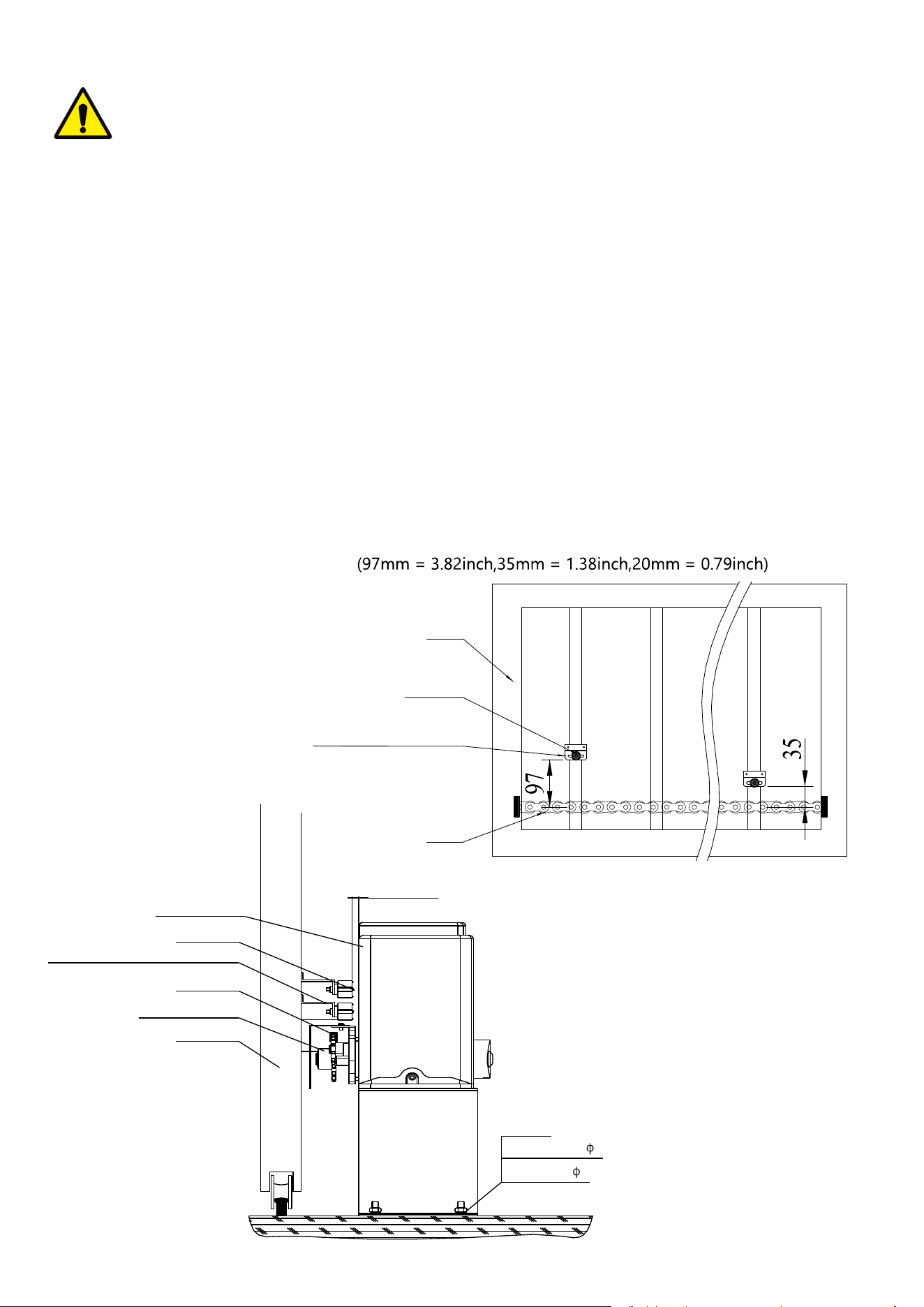
Warnings
·To ensure safety, install safety stop blocks on both ends of the rails to prevent the gate out of the rail. Before
installing the main engine, make sure that the safety stop blocks are in place and whether it has the function
of preventing the gate from moving out of the rail and out of the safety range.
·Please ensure that the main engine and its components have good mechanical properties, and the gate can
operate flexibly when moved by hands before installing the main engine.
·In this product, one control can drive one main engine only, otherwise, the control system will be damaged.
·Earth leakage circuit breaker must be installed where the gate movement can be seen, and the minimum
mounting height is 4.92ft to protect it from being touched.
·After installation, please check whether the mechanical property is good or not, whether gate movement
after manual unlocking is flexible or not, and whether the infrared sensor (optional) is installed correctly and
effectively.
Limit switch adjustment
Use the manual release key to unlock gate opener and manually move the gate to the predetermined
position; fix the magnetic limit switch block and close the clutch; testing run after power on, slightly adjust the
position of the magnetic limit switch block until the gate reaches the desired open and close limit location.
Installation of magnetic limit switch bock
GateGate
MagnetMagnet
MagneticMagnetic limitlimit switchswitch blockblock
ChainChain
GateGate
MainMain engineengine
chainchain wheelwheel
ChainChain
MagneticMagnetic limitlimit switchswitch blockblock
MagnetMagnet
≤20mm
Spring washer 8
Nut M8
Flat washer 8
9
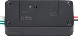
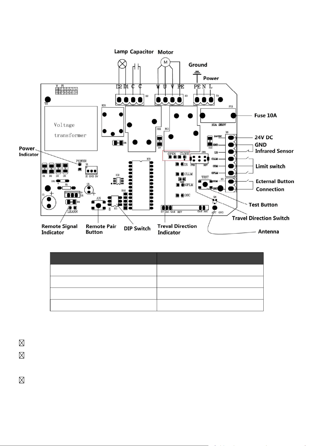
control board
Connections and Indicators Diagram
Features
Pair with up to 20 different 433.92 MHz remote controls and with wireless keypads.
Compatible with and easily connected to alarm lamps, external control buttons, and infrared
photocell sensors.
Auto-close functionality for improved security.
Connection Interface Terminals
Power X4:PE, N, L
Caution/Alarm Lamps X2:D1, D2
External Button X5: COM, OSC
Photocell Infrared Sensor X6: 24VDC, GND, I.R
10
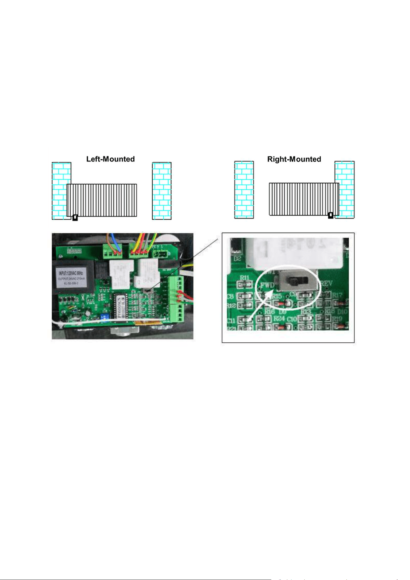
Gate Opener Installation
Step 1
Ensure your gate can glide back and forth smoothly by hand before installing the gate opener.
Step 2
Toggle the Travel Direction Switch on the control board according to the installation location of your
automatic gate opener. Flip the switch to FWD for right-mounted gate openers. Flip the switch to
REV for left-mounted gate openers.
Step 3
Wire the control board to your automatic gate opener and any compatible accessories according to
the Connections and Indicators Diagram in the Product Overview section of this manual and the
instruction manuals for the other devices.
Step 4
Press the test button, Travel direction indicator (open) will light when the gate is opening; Travel
direction indicator (close) will light when the gate is closing.

11
Remote Control
The included remote control uses single-button mode. Each button
on the remote control can pair with one control board. When
pressed, the paired button will open the gate if the gate is closed,
close the gate if the gate is open, and stop the gate if the gate is
traveling.
CAUTION: To prevent accidents, DO NOT pair one button with two different control boards.
The transmitter has been matched to the door opener when it leaves the factory, No need to match
again when the product is received.
Remote Control Pairing:
Step 1
Step 2
Press the button on the remote control to be paired. The Remote Signal Indicator will go off.
Step 3
Press the same button the remote control. The Remote Signal Indicator will flash quickly then go
off. DONE!
Remove All Paired Remote Controls:
Hold Remote Pair Button (AN1) on the control board until the Remote Signal Indicator (LED2)
goes out. DONE!
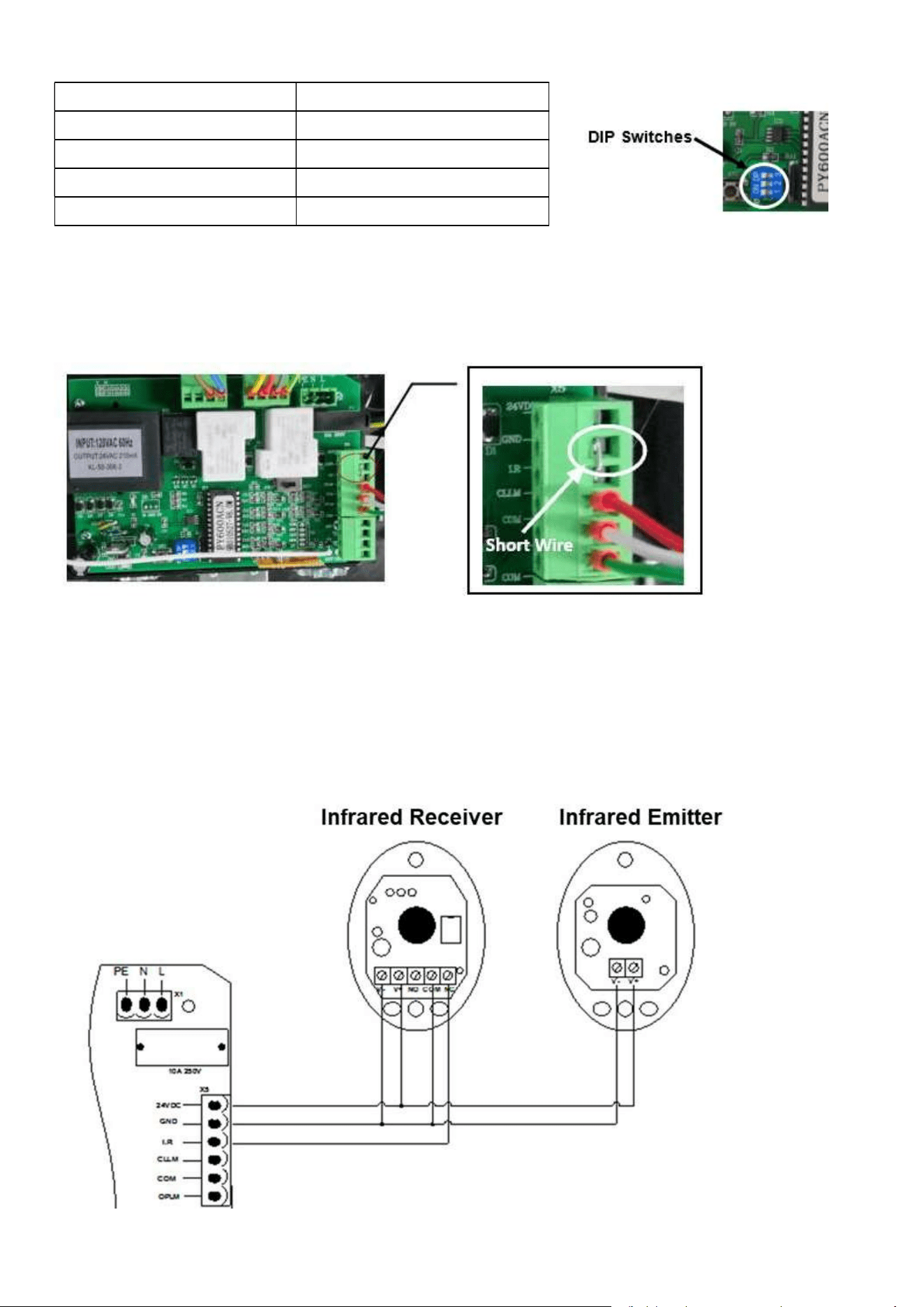
DIP Switches
The DIP switches on the control board control the external buttons control mode and the auto-close
time settings.
Switch 1: External Buttons Settings
ON = external button only can open the gate
OFF = external button can open/stop/close the gate
Press the Remote Pair Button (AN1) on the control board. The Remote Signal Indicator (LED2) will
come on.
12
Switches 2 & 3: Auto-Close Time Settings
Switch Orientations Auto-Close Time
2 ON 3 OFF 15 seconds
2 OFF 3 ON 30 seconds
2 OFF 3 OFF 45 seconds
2 ON 3 ON Auto-Close Disabled
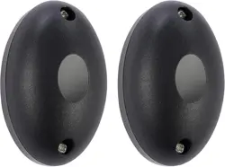
Photocell Infrared Sensor Installation
Step 1
Remove the short wire connecting the I.R and GND interface terminals on the control board.
Step 2
Install the photocell infrared sensor on your gate posts according the instructions of your photocell
infrared sensor.
Step 3
Connect the sensor to the control board according to the image below.
13
Troubleshootin
g
Problems Possible Reasons Solutions
The gate cannot open or
close normally, and LED
does not light.
1.The power is off.
2.Fuse is burned.
3.Control board power wiring
with problem.
1.Switch on the power supply.
2.Check the fuse (code FU), change the
fuse if burnt.
3.Re wiring according to instructions.
The gate can open but
cannot close.
1.Photocell wiring with problem.
2.Photocell mounting wit
h
problem.
3.Photocell is blocked by
objects.
4.Sensitivity of obstacle is t
oo
high (Intelligent type).
5.Hall switch parts is damaged
(Intelligent type).
1.If not connect photocell, please make sure
that the infrared port and GND short circuit;
if connect infrared sensor, please make sure
the wiring is correct and the photocell is
N.C.
2.Make sure that the photocell mounting
position can be mutually aligned.
3.Remove the obstacle.
4.Reduce the sensitivity of obstacle.
5.Change hall switch parts.
Remote control doesn’t
work.
1.Battery level of the remote
control is low.
2.Remote control learning is not
completed.
1.Change the remote control battery.
2.Re-conduct remote control learning.
Press OPEN, CLOSE
button, the gate is not
moving, motor has noise.
1.Capacitor is broken.
2.Capacitor is poor connected.
3.Gate moving is not smoothly.
1.Change capacitor.
2.Check the capacitor wiring.
3.According to the actual situation to adjust
the motor or the gate.
Not stop at the limit
position when opening /
closing.
1. The limit direction is wrong.
2. The mounting of magnetic
limit switch with problem.
1.Check whether the limit switch wiring is
consistent with the actual direction of
operation.
2. Check whether the distance between
magnetic limit switch and motor, and the
height of the magnetic limit switch can reach
up the mounting requirement.
Leakage switch tripped.
Power supply line short circuit
or motor line short circuit.
Check wiring.
Remote control working
distance is too short.
Signal is blocked.
Connect external receiver antenna, 1.5
meters above ground.
Contact Us
Thank you for choosing our products! If you have any questions or comments, contact us at
help@cs-supportpro.com
and we'll resolve your issue ASAP!
For a .pdf copy of the latest version of these instructions, use the appropriate app on your
smartphone to scan the QR code to the right.
SGO-0000-00 Rev. 24 Jun. 2022