
LAUNCH
i
Trademarks
LAUNCH is a registered trademark of LAUNCH TECH CO., LTD. in China and other countries.
Android is a trademark of Google LLC. All other marks are trademarks or registered trademarks of their respective
owners.
Copyright Information
Copyright © LAUNCH TECH CO., LTD. (also called LAUNCH for short). All rights reserved. No part of this publication
may be reproduced, stored in a retrieval system, or transmitted in any form or by any means - electronic, mechanical,
photocopying, recording, or otherwise - without the prior written permission of LAUNCH.
Statement: LAUNCH owns the complete intellectual property rights for the software used by this product. For any
reverse engineering or cracking actions against the software, LAUNCH will block the use of this product and reserve the
right to pursue their legal liabilities.
Disclaimer of Warranties and Limitation of Liabilities
All information, illustrations, and specifications in this manual are based on the latest information available at the time of
publication.
LAUNCH reserves the right to make changes at any time without notice. LAUNCH shall not be liable for any direct,
special, incidental, indirect damages or any economic consequential damages (including loss of profits) arising from the
use of this document.
Using This Manual
This manual contains instructions for operating the device.
Some illustrations in this manual may contain modules and optional equipment that are not included in your system.
The following conventions are used:
Bold Text
Bold text highlights selectable items such as buttons and menu options.
Notes
A NOTE provides helpful information such as additional explanations, tips, and comments.
Warning
Warning indicates a hazardous situation which, if not avoided, could result in minor or moderate injury to the operator or
to bystanders.
Danger
Danger indicates an imminently or potentially hazardous situation which, if not avoided, could result in death or serious
injury to the operator or to bystanders.
Illustrations
Illustrations in this manual are for reference only. Actual testing screen may vary depending on the vehicle being tested.
Always follow menu titles and on-screen instructions to make correct selections.

LAUNCH
ii
Important Safety Precautions
To avoid personal injury, property damage, or accidental damage to the product, read all information in this section
before using the product.
DANGER
• When an engine is operating, keep the service area well-ventilated or attach a building exhaust removal system to
the engine exhaust. Engines produce various poisonous compounds (hydrocarbon, carbon monoxide, nitrogen
oxides, etc.) that may cause loss of consciousness, serious injury, or death.
• Use only the included battery and power adaptor. There is risk of explosion if the battery is replaced with an incorrect
type.
• If you must drive the vehicle in order to perform a troubleshooting procedure, always have a second person assist
you. Trying to drive and operate the diagnostic tool at the same time is dangerous, and could cause a serious traffic
accident.
WARNING
Always perform automotive testing in a safe environment.
Do not connect or disconnect any test equipment while the ignition is ON or the engine is running.
Before starting the engine, place the gear lever in Neutral (for manual transmission) or Park (for automatic
transmission) to prevent unexpected movement.
NEVER smoke or allow sparks or open flames in vicinity of battery or engine. Do not operate the tool in explosive
atmospheres, such as in the presence of flammable liquids, gases, or heavy dust.
Keep a fire extinguisher suitable for gasoline/chemical/electrical fires nearby.
Wear an ANSI-approved eye shield when testing or repairing vehicles.
Put wheel chocks in front of the drive wheels and never leave the vehicle unattended during testing.
Use extreme caution around ignition coils, distributor caps, ignition wires, and spark plugs. These components carry
hazardous voltage when the engine is running.
To avoid damaging the tool or generating false data, ensure the vehicle battery is fully charged and the connection to
the vehicle DLC (Data Link Connector) is clear and secure.
Retrieving and using Diagnostic Trouble Codes (DTCs) for troubleshooting vehicle operation is only one part of an
overall diagnostic strategy. Never replace a part based only on the DTC definition. Each DTC has a set of testing
procedures, instructions and flow charts that must be followed to confirm the location of the problem. This information
can be found in the vehicle’s service manual.
Automotive batteries contain sulfuric acid that is corrosive and harmful to skin. Avoid direct contact with automotive
batteries during operation. Keep ignition sources away from batteries at all times.
Keep the tool dry, clean, free from oil, water or grease. Use a mild detergent on a clean cloth to clear the outside of
the equipment if necessary.
Keep clothing, hair, hands, tools, and test equipment away from all moving or hot engine parts.
Store the tool and accessories in a locked area out of reach of children.
Do not use the tool while standing in water.
Do not expose the tool or power adapter to rain or moisture. Water ingress increases the risk of electric shock.
This tool is a sealed and contains no user-serviceable parts. All internal repairs must be performed by an authorized
service center or qualified technician. For inquiries, contact your dealer.
Keep the tool far away from magnetic devices, as magnetic fields may damage the screen or erase stored data.
Do not attempt to replace the internal rechargeable lithium battery. Contact your dealer for factory replacement.
Do not disconnect the vehicle battery or wiring cables while the ignition switch is ON, as this may damage sensors or
the Electronic Control Unit (ECU).

LAUNCH
iii
Do not place magnetic objects near the ECU. Disconnect the power supply to the ECU before performing any
welding operations on the vehicle.
Use extreme caution when working near the ECU or sensors. Ground yourself before handling Programmable Read
Only Memory (PROM) components to avoid damaging the ECU or sensors due to static electricity.
When reconnecting the ECU harness connector, ensure it is attached firmly. Otherwise, internal electronic
components such as ECU Integrated Circuits (ICs) may be damaged.
Compliance Information
MODEL: X-431 PAD5 ELITE V2
FCC ID: XUJOADDPD1005A
HVIN: X-431 PAD5 ELITE V2
IC: 29886-OADDPD1005A
Any Changes or modifications not expressly approved by the party responsible for compliance could void the user's
authority to operate the equipment.
This device contains licence-exempt transmitter(s)/receiver(s) that comply with Innovation, Science and Economic
Development Canada's licence-exempt RSS(s) and part 15 of the FCC Rules. Operation is subject to the following two
conditions:
(1) This device may not cause harmful interference, and (2) this device must accept any interference received, including
interference that may cause undesired operation.
L’émetteur/récepteur exempt de licence contenu dans le présent appareil est conforme aux CNR d’Innovation,
Sciences et Développement économique Canada et à la partie 15 des règles de la FCC applicables aux appareils radio
exempts de licence. L’exploitation est autorisée aux deux conditions suivantes:
(1) L’appareil ne doit pas produire d’interférences nuisibles, et (2) L’appareil doit accepter tout brouillage radioélectrique
reçu, même si le brouillage est susceptible d’en compromettre le fonctionnement.
This device complies with Canadian CAN ICES-003(B) / NMB-003(B).
Cet appareil est conforme à la norme canadienne CAN ICES-003(B) / NMB-003(B).
The device for operation in the band 5150-5250MHz is only for indoor use.
Note: This equipment has been tested and found to comply with the limits for a Class B digital device, pursuant to part
15 of the FCC Rules. These limits are designed to provide reasonable protection against harmful interference in a
residential installation. This equipment generates, uses and can radiate radio frequency energy and, if not installed and
used in accordance with the instructions, may cause harmful interference to radio communications. However, there is
no guarantee that interference will not occur in a particular installation. If this equipment does cause harmful
interference to radio or television reception, which can be determined by turning the equipment off and on, the user is
encouraged to try to correct the interference by one or more of the following measures:
- Reorient or relocate the receiving antenna.
- Increase the separation between the equipment and receiver.
- Connect the equipment into an outlet on a circuit different from that to which the receiver is connected.
- Consult the dealer or an experienced radio/TV technician for help.
Specific Absorption Rate (SAR) information
This product meets the government's requirements for exposure to radio waves. The guidelines are based on standards
that were developed by independent scientific organizations through periodic and thorough evaluation of scientific
studies. The standards include a substantial safety margin designed to assure the safety of all persons regardless of
age or health.
RF Exposure Information and Statement
The SAR limit is 1.6 W/kg averaged over one gram of tissue. This device has also been tested against this SAR limit.
This device was tested for typical body-worn operations 0mm from the body. To maintain compliance with RF exposure
Under certification
L'appareil destiné à fonctionner dans la bande 5150-5250MHz est réservé exclusivement à un usage intérieur.
L'appareil destiné à fonctionner dans la bande 5150?5350?MHz est réservé exclusivement à un usage intérieur.

LAUNCH
iv
requirements, use accessories that maintain a 0mm separation distance between the user's body.
Body-worn Operation
This device was tested for typical body-worn operations. To comply with RF exposure requirements, a minimum
separation distance of 0mm must be maintained between the user’s body, including the antenna. Third-party belt-clips,
holsters, and similar accessories used by this device should not contain any metallic components. Body-worn
accessories that do not meet these requirements may not comply with RF exposure requirements and should be
avoided. Use only the supplied or an approved antenna.
Cet appareil a été testé pour des opérations typiques portées sur le corps, pour satisfaire aux exigences relatives à
l’exposition RF, une distance minimale de séparation de 0mm doit être maintenue entre le corps de l’utilisateur, y
compris l’antenne. Les clips de ceinture, les étuis et les accessoires similaires de tiers utilisés par cet appareil ne
doivent pas contenir de composants métalliques. Les accessoires portés sur le corps qui ne répondent pas à ces
exigences ne peuvent pas être conformes aux exigences relatives à l’exposition RF et doivent être évités. Utilisez
uniquement l’antenne fournie ou une antenne approuvée.
This device is in compliance with the essential requirements and other relevant provisions of Radio Equipment Directive
2014/53/EU. The RF frequencies can be used in Europe without restriction.
본 제품의 전자파흡수율은 과학기술정보통신부의 '전자파 인체보호기준'을 만족합니다" 내용 기재하겠습니다 외에,
본 제품은 국립전파연구원의 '전자파흡수율 측정기준'에 따라 최대 출력 조건에서 몸통에 1 cm 이격하여
시험되었습니다.
MODEL: S4006
FCC ID: XUJS4006
HVIN: S4006
IC: 29886-S4006
Any Changes or modifications not expressly approved by the party responsible for compliance could void the user's
authority to operate the equipment.
This device contains licence-exempt transmitter(s)/receiver(s) that comply with Innovation, Science and Economic
Development Canada's licence-exempt RSS(s) and part 15 of the FCC Rules. Operation is subject to the following two
conditions:
(1) This device may not cause harmful interference, and (2) this device must accept any interference received, including
interference that may cause undesired operation.
L’émetteur/récepteur exempt de licence contenu dans le présent appareil est conforme aux CNR d’Innovation,
Sciences et Développement économique Canada et à la partie 15 des règles de la FCC applicables aux appareils radio
exempts de licence. L’exploitation est autorisée aux deux conditions suivantes:
(1) L’appareil ne doit pas produire d’interférences nuisibles, et (2) L’appareil doit accepter tout brouillage radioélectrique
reçu, même si le brouillage est susceptible d’en compromettre le fonctionnement.
This device complies with Canadian CAN ICES-003(B) / NMB-003(B).
Cet appareil est conforme à la norme canadienne CAN ICES-003(B) / NMB-003(B).
The device for operation in the band 5150-5250MHz is only for indoor use.
Note: This equipment has been tested and found to comply with the limits for a Class B digital device, pursuant to part
15 of the FCC Rules. These limits are designed to provide reasonable protection against harmful interference in a
residential installation. This equipment generates, uses and can radiate radio frequency energy and, if not installed and
used in accordance with the instructions, may cause harmful interference to radio communications. However, there is
no guarantee that interference will not occur in a particular installation. If this equipment does cause harmful
interference to radio or television reception, which can be determined by turning the equipment off and on, the user is
encouraged to try to correct the interference by one or more of the following measures:
- Reorient or relocate the receiving antenna.
Under certification
L'appareil destiné à fonctionner dans la bande 5150-5250MHz est réservé exclusivement à un usage intérieur.

LAUNCH
v
- Increase the separation between the equipment and receiver.
- Connect the equipment into an outlet on a circuit different from that to which the receiver is connected.
- Consult the dealer or an experienced radio/TV technician for help.
The device complies with FCC & IC Radiation exposure limits set forth for uncontrolled environment. This device should
be installed and operated with minimum distance 20cm between the radiator and your body.
L'appareil est conforme aux limites d'exposition aux radiations de la FCC & IC définies pour un environnement non
contrôlé. Cet appareil doit être installé et utilisé avec une distance minimale de 20 cm entre le radiateur et votre corps.
This device is in compliance with the essential requirements and other relevant provisions of Radio Equipment Directive
2014/53/EU. The RF frequencies can be used in Europe without restriction.

LAUNCH
vi
TABLE OF CONTENTS
1 Introduction .................................................................................................................................................................. 1
1.1 Packing List ............................................................................................................................................................. 1
1.2 Components & Controls .......................................................................................................................................... 1
1.2.1 Scan Tool.......................................................................................................................................................... 1
1.2.2 SmartLink C Device ......................................................................................................................................... 3
1.3 Technical Specifications .......................................................................................................................................... 5
2 Getting Started ............................................................................................................................................................. 6
2.1 Charging & Powering On ........................................................................................................................................ 6
2.2 Screen Layout ......................................................................................................................................................... 6
2.3 Language Setup ...................................................................................................................................................... 6
2.4 Network Setup ......................................................................................................................................................... 6
2.5 Registration & Update ............................................................................................................................................. 7
2.6 Job Menu ................................................................................................................................................................ 8
3 Connection & Communication Setup ....................................................................................................................... 10
3.1 Connection ............................................................................................................................................................ 10
3.2 Communication Setup ........................................................................................................................................... 10
4 Diagnosis & Service Functions ................................................................................................................................ 12
4.1 Intelligent Diagnose ............................................................................................................................................... 12
4.1.1 AI Diagnostics ................................................................................................................................................ 12
4.1.2 Auto Detect ..................................................................................................................................................... 12
4.2 Diagnose (Manual Select) ..................................................................................................................................... 12
4.3 Remote Diagnose ................................................................................................................................................. 19
4.3.1 SmartLink Super Remote Diagnosis .............................................................................................................. 19
4.3.2 X431 Remote Diagnosis ................................................................................................................................ 21
4.4 EV Diagnose ......................................................................................................................................................... 25
4.4.1 Vehicle Diagnosis ........................................................................................................................................... 25
4.4.2 Battery Pack Detection ................................................................................................................................... 25
4.5 Service Function ................................................................................................................................................... 27
4.6 Feedback .............................................................................................................................................................. 27
5 Software Update ......................................................................................................................................................... 28
5.1 Update Diagnostic Software & APP ...................................................................................................................... 28
5.2 Update Frequently Used software ......................................................................................................................... 28
5.3 Renew Subscription .............................................................................................................................................. 29
6 Toolbox........................................................................................................................................................................ 30
6.1 Battery Equalizer ................................................................................................................................................... 30
6.2 Battery Charger & Discharger ............................................................................................................................... 30
6.3 TPMS .................................................................................................................................................................... 30
6.4 ADAS (Calibration) ................................................................................................................................................ 30
6.5 Oscilloscope .......................................................................................................................................................... 30
6.6 Sensor Simulator ................................................................................................................................................... 31
6.7 Videoscope ........................................................................................................................................................... 31
6.8 BST360 (Battery Tester) ....................................................................................................................................... 31

LAUNCH
vii
6.9 Multimeter ............................................................................................................................................................. 31
6.10 Current Clamp ..................................................................................................................................................... 31
6.11 Insulation Tester .................................................................................................................................................. 31
6.12 Immobilizer Programmer ..................................................................................................................................... 31
6.13 Key Programmer ................................................................................................................................................. 31
7 Diagnosis Kit .............................................................................................................................................................. 32
7.1 Vehicle Coverage .................................................................................................................................................. 32
7.2 CAN Bus Pin Detection ......................................................................................................................................... 32
7.3 CANScope ............................................................................................................................................................ 32
7.4 Diagnostic Software Clear ..................................................................................................................................... 32
7.5 Firmware Fix ......................................................................................................................................................... 32
7.6 Data Stream Sample ............................................................................................................................................. 32
7.7 Battery Voltage ...................................................................................................................................................... 32
7.8 Reset MSVIN ........................................................................................................................................................ 32
7.9 Diagnostic History ................................................................................................................................................. 32
7.10 Vehicle QR .......................................................................................................................................................... 32
8 User Info ...................................................................................................................................................................... 33
8.1 My Report .............................................................................................................................................................. 33
8.2 My VCI .................................................................................................................................................................. 33
8.3 Profile .................................................................................................................................................................... 33
8.4 My Order ............................................................................................................................................................... 33
8.5 Reset Password .................................................................................................................................................... 33
8.6 My Software .......................................................................................................................................................... 33
8.7 VCI Management .................................................................................................................................................. 33
8.8 Login/Log out ........................................................................................................................................................ 33
9 Other Modules ............................................................................................................................................................ 34
9.1 License List ........................................................................................................................................................... 34
9.2 My Points .............................................................................................................................................................. 34
9.3 Error Correction ..................................................................................................................................................... 34
9.4 Complaint & Suggestion ........................................................................................................................................ 34
9.5 Settings ................................................................................................................................................................. 34
9.5.1 Diagnostic Setup ............................................................................................................................................ 34
9.5.2 X Button Customization Settings .................................................................................................................... 34
9.5.3 Shop Information ............................................................................................................................................ 34
9.5.4 Printer Set ...................................................................................................................................................... 34
9.5.5 Clear Cache ................................................................................................................................................... 35
9.5.6 About .............................................................................................................................................................. 35
9.5.7 Diagnostic Software Auto Update................................................................................................................... 35
9.5.8 Device Account Management ........................................................................................................................ 35
10 J2534 Reprogramming Using SmartLink C ........................................................................................................... 36
11 FAQs .......................................................................................................................................................................... 37


LAUNCH
1
1 Introduction
1.1 Packing List
Common accessories are identical, but accessories may vary for different destination markets. For detailed accessory
information, please consult the seller or refer to the packing list included with the tool.
1. Scan tool (model: X-431 PAD5 ELITE V2) x 1
2. SmartLink C device (model: S4006) x 1
3. Diagnostic cable x 1
4. Power adaptor x 1 (including 4 interchangeable adaptors)
5. Type-A to Type-B data cable x 1
6. Type-A to Type-C cable x 1
7. Password envelope x 1
8. Crossover cable x 1
9. Multilingual Quick Start Guide x 1
10. User Manual x 1
11. Non-16pin Adaptor Kit x 1
1.2 Components & Controls
There are two main components to the diagnostic system: Scan Tool and SmartLink C Device.
1.2.1 Scan Tool
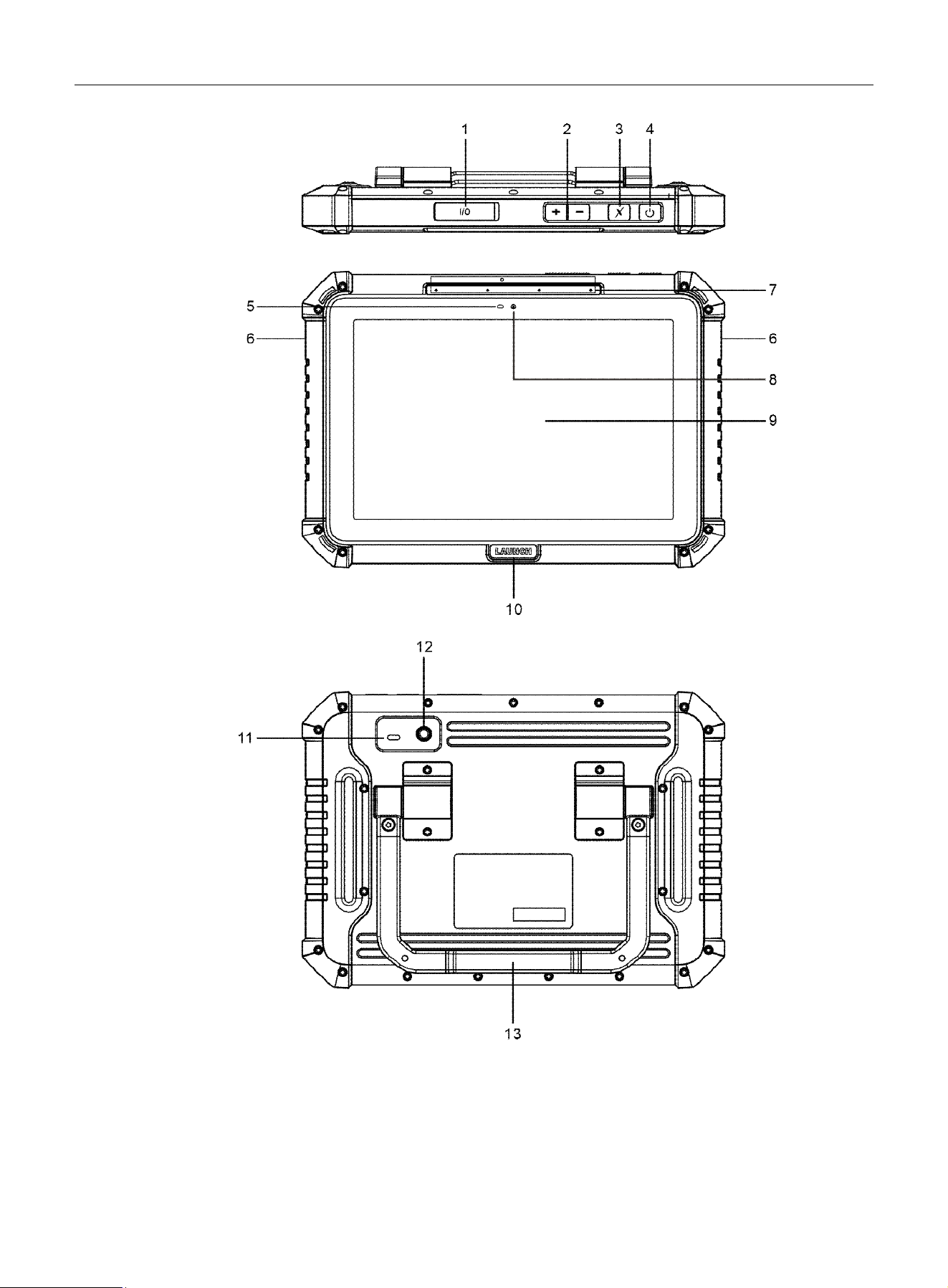
The scan tool acts as the central processing system, which receives and analyzes live vehicle data from the SmartLink
C device and outputs the test result.
LAUNCH
2
1. Data I/O Port
1). Type-A Port
• Connect to the SmartLink C device to perform vehicle diagnosis.
• Connect to the SmartLink C device to power it, allowing for firmware version upgrades.
• Connect to the add-on module to extend the functions of the scan tool.

LAUNCH
3
2). Type-C Port
• Charge the scan tool via the power adaptor.
• Connect to a PC for data exchange.
2. Volume Buttons
Adjust the volume.
Note: Press and hold [POWER] and [VOL -] keys to capture a screenshot.
3. Custom Function Button
Press to assign a preferred function shortcut. The button can be configured via Other Modules -> Settings -> X
Button Customization Settings.
4. Power Button
Turn the scan tool on/off.
5. Ambient Light Sensor
6. Audio Speaker
7. Microphones
Convert voice into an electrical signal.
8. Front Camera
Take pictures of the view ahead the screen.
9. Touch Screen
Display test results.
10. Breathing Light
The breathing light effect is disabled by default. User can turn it on in Settings -> Display -> Breathing light.
Notes: The breathing light behavior is defined as follows:
1). When not charging:
•
When the screen lights up, the light illuminates solid white.
•
When the screen is off, the light does not function.
2). When charging (the tool will power on automatically):
The light pulses white during charging. When fully charged, the light illuminates solid white.
11. Camera Flash
Produce artificial illumination.
12. Rear Camera
Take pictures of the view in front of the scan tool.
13. Adjustable Kickstand
Flip out it to any angle for comfortable use at your desk, or hang it on automotive part.
1.2.2 SmartLink C Device
The SmartLink C device features powerful functions and it can be applied in the following situations:
1). When used as a VCI (Vehicle Communication Interface), it works in conjunction with the Diagnose module of the
scan tool to obtain vehicle data, then sends it to the scan tool for analysis wirelessly or via data cable.
2). When used as a SmartLink C (Customer) dongle, it does not communicate with the scan tool directly, but works with
the SmartLink module of the scan tool. The scan tool is mainly used to issue remote diagnostic requests, and the
SmartLink C dongle connects the network to receive and execute commands from the remote SmartLink B
(Business).
3). When used as a local J2534 PassThru device, it can work with a PC installed with OEM diagnostic software.
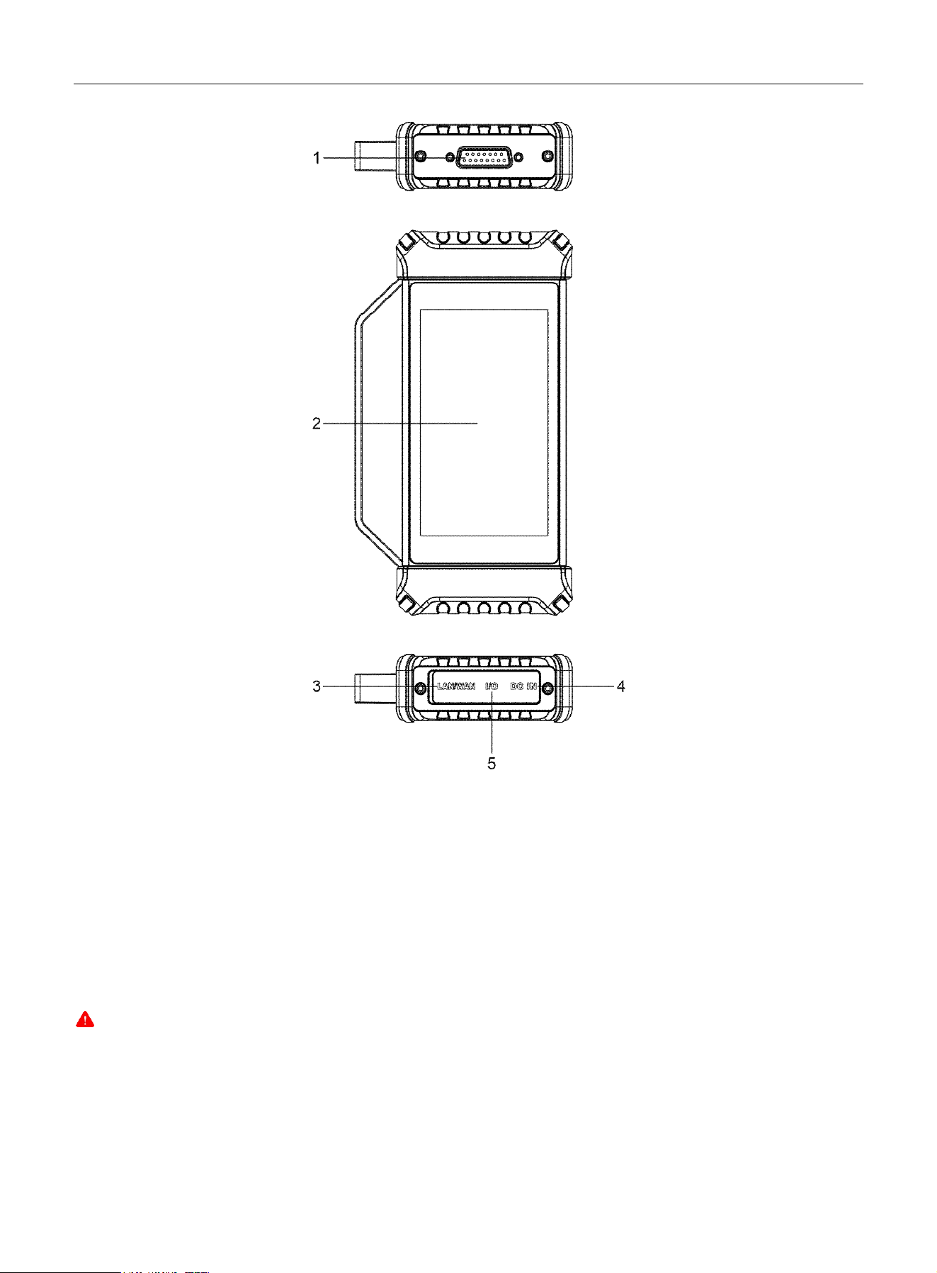
LAUNCH
4
1. DB-15 Diagnostic Connector
Connect the SmartLink C device to the vehicle’s DLC (Data Link Connector) port via the diagnostic cable.
2. Touch Screen
3. LAN/WAN Port
Connect the SmartLink C device to the Internet via the crossover cable. This applies only to the SmartLink Super
Remote Diagnostics.
4. DC-IN Power Jack
It can obtain power via connecting the diagnostic cable to the vehicle’s DLC port or connecting to an external DC power
supply.
Warning: It is prohibited to connect this power jack to an external DC power supply when the SmartLink C device is properly
connected to the vehicle’s DLC port.
No responsibility can be assumed for any damage or loss caused by failure to strictly following this warning.
5. Data I/O Port
• Connect to the scan tool to perform vehicle diagnosis/update SmartLink C device firmware.
• Connect to a PC to perform J2534 reprogramming when used as a J2534 PassThru device.

LAUNCH
5
1.3 Technical Specifications
1. Scan tool
Operating System: Andriod
TM
15
CPU: 8-core Processor
Display: 10.1 inch touch screen with resolution of 1920 x 1200
RAM: 8GB
Storage: 256GB
Connectivity:
• Dual Wi-Fi (One supports 802.11a/b/g/n/ac; and the other supports 802.11a/b/g/n/ac/ax)
• I/O ports (Type-A x 1 + 1 x Type-C x 1)
Camera: 8MP front-facing + 13MP rear-facing
Dimension: 287.2mm x 203.5mm x 45.9mm
Supported Protocols: CAN2.0/CANFD/DOIP/J2534/RP1210/D-PDU
Operating temperature: 0℃- 50℃(32°F to 122°F)
Note: Operating temperature refers to the temperature at which the scan tool functions normally in non-charging status.
Storage temperature: -20℃-70℃(-4°F ~158°F)
2. SmartLink C device
Dimension: 187.6mm x 106mm x 32.8mm
Working voltage: DC 8-36V
Power consumption: ≤8.4W
Communication: wireless/wired
Dimension: 187.6mm x 106mm x 32.8mm
Operating temperature: 0℃-50℃(32°F to 122°F)

LAUNCH
6
2 Getting Started
2.1 Charging & Powering On
Notes:
•
Only use the included power adaptor to recharge the tool. Use of any other adaptor will damage the tool. We assume no
responsibility for damage or loss resulting from using adaptors other than the specified one.
•
Always charge on a non-flammable surface in a well-ventilated area.
Follow the steps below to charge the scan tool:
1. Connect one end of the power adaptor to the Type-C port of the tool, and the other end to an AC outlet. The tool will
power on automatically.
2. When charging, the breathing light (if the breathing light effect is turned on) flashes white and a charging symbol
appears on the screen.
3. When the light illuminates solid white, the battery is fully charged. Disconnect the power adaptor from the AC outlet.
4. To turn the tool off, press and hold the POWER button until an options menu appears. Tap Power Off.
2.2 Screen Layout
On-screen keys and the status bar at the bottom of the screen are as follows:
Tap
to return to the previous screen or exit the application.
Tap to jump to the home screen.
Tap to display a list of currently running or recently used applications.
Tap
to capture the current screen. All screenshots are stored in the Screenshots folder.
indicates whether the VCI is connected properly.
Tap to open apps in split-screen mode for seamless multi-tasking.
2.3 Language Setup
The scan tool supports multiple languages. To change the system language:
1. On the home screen, tap Settings -> System -> Language -> System Languages.
2. Tap the desired language from the list and the system will switch to the chosen language.
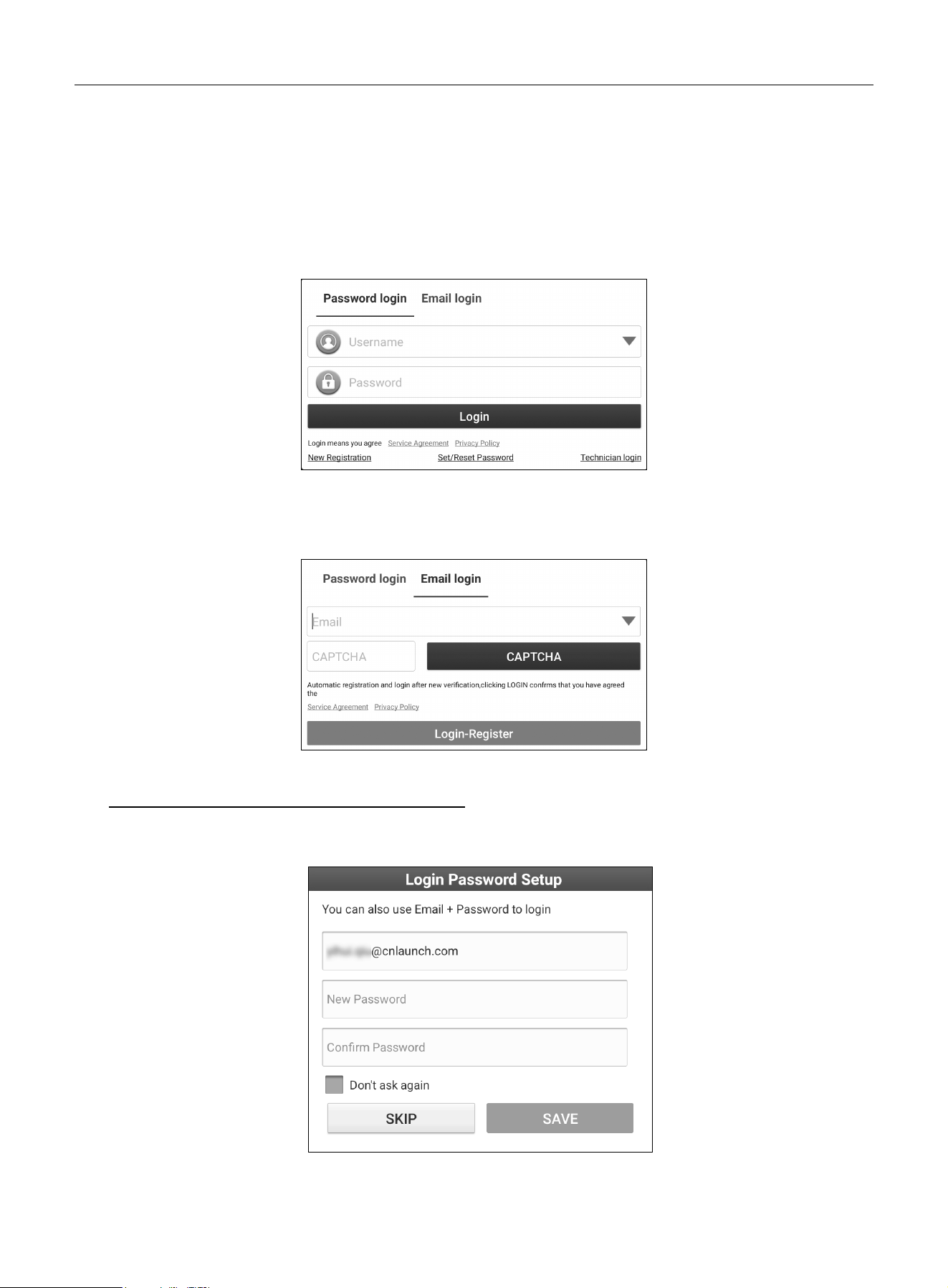
2.4 Network Setup
The scan tool has dual built-in Wi-Fi modules. One communicates with the SmartLink C device, and the other allows the
tool to access the Internet. Once online, you can register your tool, update diagnostic software & APK, browse the
Internet, and send email.
Note: When WLAN is set as ON, the tool will consume more power. Turn it off when not in use to conserve battery.
1. On the home screen, tap Settings -> Network & internet -> Internet.
2. Tap or slide the Wi-Fi switch to ON, the tool will start searching for available wireless networks.
3. Choose the desired Wi-Fi access point / network:
If open, connect directly.
If encrypted, enter the correct security key (network password).
LAUNCH
7
The tool will automatically connect to a previously linked network when in range.
2.5 Registration & Update
For new users, you must complete the user registration process before getting started.
Tap the application icon on the home screen, then tap Login on the upper right corner of the screen. The following
pop-up will appear.
There are two methods available for users to login: Password login and Email login.
1. If you have not registered any authorized account of LAUNCH scan tool, use Email login. Tap New Registration, the
following screen will appear.
Input the Email address, tap CAPTCHA, and enter the received verification code. Tap Login-Register to continue.
A. If no scan tools have been bound to this Email before, follow the steps below to proceed:
1). The system will prompt you to set a new password. After the password is set, you can use the email and password
to log into the diagnostic app on the Password Login screen in the future.
If you skip this step, you can also set it at any time by tapping the Set/Reset Password on the “Password login”
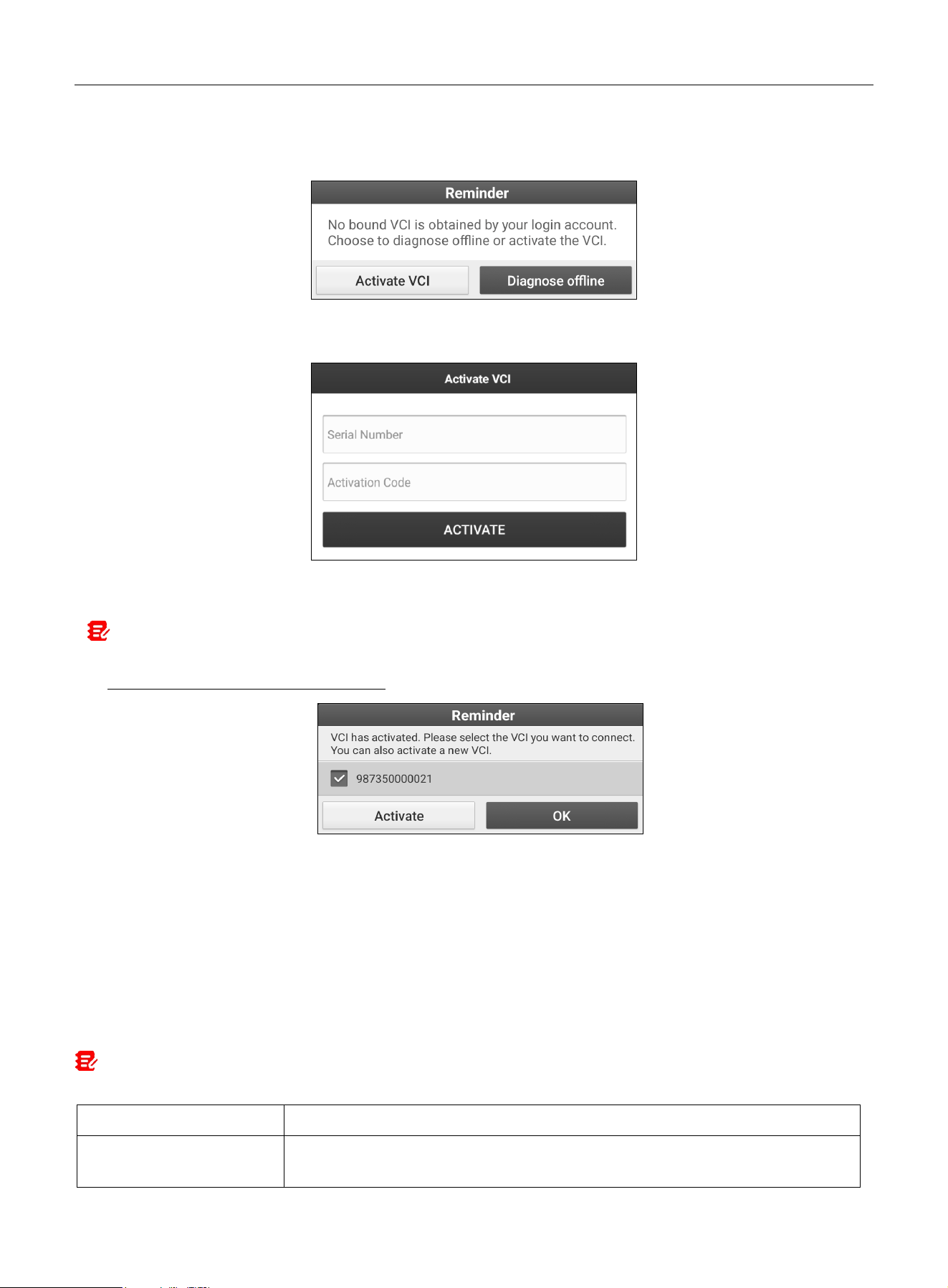
LAUNCH
8
screen.
2). After the following pop-up appears, tap ACTIVATE VCI to proceed.
3). Enter the 12-digit Product Serial Number and 8-digit Activation Code (from the password envelope), then tap
ACTIVATE.
4). After the VCI device is activated successfully, the system automatically enters the update center. Tap Update to
install all available software.
Note: All software is updated periodically. It is recommended to check regularly for updates and install the latest software
version for the best service, functions and experience.
B. If there are scan tools bound to this Email, a list of the bound VCIs will pop up. In this case,
1). Tap Activate. Enter the Product Serial Number and Activation Code, then tap Activate.
2). Go to Software Update to update all available software.
2. If you already have an authorized account of LAUNCH scan tool, use Password login. Enter username and password
(If you forgot the password, tap Set/Reset Password to create a new one), and tap Login to access the diagnostic
system.
2.6 Job Menu
It mainly includes the following items:
Note: The description of the following function menus is for reference only. Due to continuing version updates and iterations
of the diagnostic APP, the actual displayed menus may vary. Please refer to the actual menus.
Name
Description
Intelligent Diagnose
•
Obtain vehicle data from the cloud server to perform quick test via reading VIN, to
avoid various defects resulting from step-by-step menu selection.

LAUNCH
9
•
Check historical repair records online.
Diagno
se
Diagnose a vehicle manually.
EV
Diagnose new-energy vehicles, detect battery packs, and perform service functions.
Note: This function needs to work with New Energy Vehicle Diagnosis Add-on Kit
(optional), which can be purchased from the authorized dealer.
Remote Diagnose
There are two remote diagnosis platforms available: SmartLink Super remote
diagnosis and X431 Remote diagnosis.
Special Function
It offers coding, reset, relearn and more service functions, to help vehicles get back to
functional status after repair or replacement.
Toolbox
Provide some additional add-on tools to extend the functions of the scan tool.
Software Update
Update vehicle diagnostic software and APK.
Diagnosis Kit
Include Vehicle Coverage, CAN BUS Pin Detection, CANScope, Diagnostic Software
Clear and Fix Connector Firmware/System etc.
Diagnostic Feedback
If you encounter unsolved problems during diagnosis, you can send your last 20 test
records to us using the Feedback function for timely technical support.
Know Your Customer
This function is mainly used to assist merchants with business opportunity analysis,
customer management, and diagnostic statistics.
Mall
Subscribe some extra software or service functions that are not integrated in the tool
online.
LAUNCH Academy
Include abundant repair case, operation skills and training videos for quick reference.
Repair Info
Check repair information and ask for support via Facebook or from after-sales team.
User Info
Manage VCI, diagnostic reports & records, change password, check order and log
out / login etc.
Other Modules
Include License List, Know Your Customer, My Points, Error Correction, Opinion
Feedback, Settings and About.
LAUNCH
10
3 Connection & Communication Setup
3.1 Connection
1. Ensure vehicle battery voltage is 9-14V (for passenger cars) or 18-30V (for commercial vehicles), and the vehicle
ignition is OFF.
2. Locate the vehicle’s DLC port.
For passenger cars, the DLC is usually located 12 inches from the center of the instrument panel, under or around the driver’s
side for most vehicles. For some vehicles with special designs, the DLC location may vary.
If the DLC cannot be found, refer to the vehicle’s service manual for the location.
For commercial vehicles, the DLC is always located in driver’s cab.
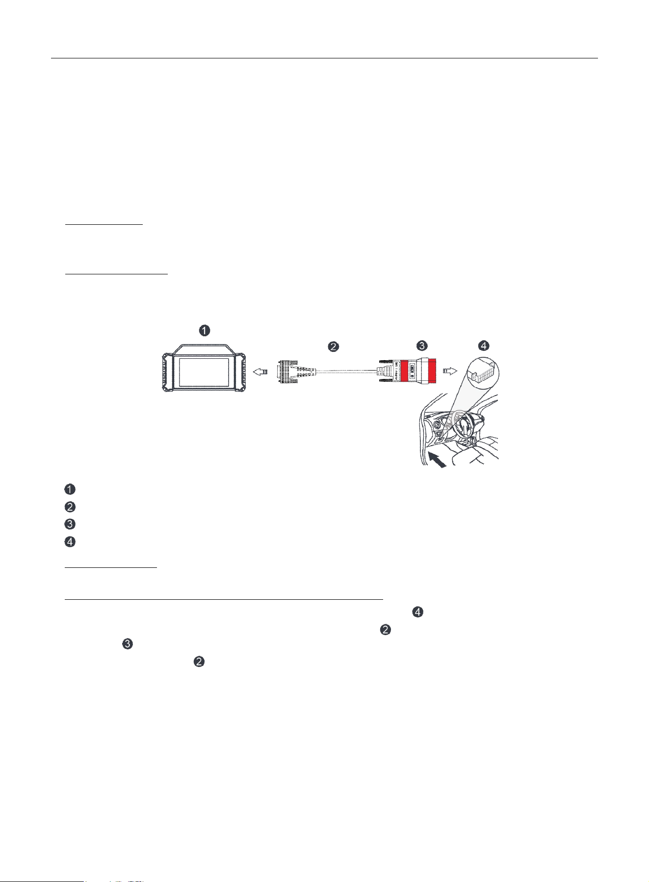
3. Refer to the following illustrations to make connection.
The method used to connect the VCI device to a vehicle’s DLC depends on the vehicle’s configuration as follows:
VCI
DB15M to HDB15F data cable
HD15M to OBDII 16M adaptor
Vehicle’s DLC port
For OBD II vehicles, use the included diagnostic cable (DB15F to HDB15F data cable and HD15M to OBDII 16M
adaptor) to connect the VCI to the vehicle’s DLC port.
For non-OBDII vehicles, refer to the above figure to make connection.
1) Select the appropriate adaptor according to the vehicle’s DLC port type ( ).
2) Loosen the captive screws of the DB15M to HDB15F data cable ( ) and disconnect the HD15M to OBDII 16M
adaptor ( ) from the data cable.
3) Connect the data cable ( ) with the target adaptor (optional) and tighten the screws. Other steps shall also
apply.
If you choose to perform vehicle diagnosis via data cable, connect one end of the data cable into the VCI, and the
other end into the Type-A port of the tool.
4. Turn the vehicle’s ignition ON with engine OFF.
5. The tool is now ready for diagnostics.
3.2 Communication Setup
The tool supports two communication methods with the VCI device: wireless and wired (USB).

LAUNCH
11
After the user registration is successfully finished, the Wi-Fi communication between the tool and the VCI device is
established automatically, and no further configuration is required. If the default Wi-Fi communication is abnormal, refer
to Chapter 8.7 to adopt alternative wireless communication method.
The USB connection is a simple and quick way to set up communication. After connecting the data cable properly
between the tool to the VCI, the VCI navigation button at the bottom of the screen will be enabled, indicating a
successful USB connection.
Note: The USB connection provides the most stable and fastest communication. When multiple communication methods are
active simultaneously, the tool uses the wired communication by default as the priority.
LAUNCH
12
4 Diagnosis & Service Functions
4.1 Intelligent Diagnose
Two methods are available for you to perform smart diagnostics: AI Diagnostics or Auto Detect.
Notes:
•
Before using this function, ensure the VCI is properly connected to the vehicle’s DLC port. For detailed connection instructions,
see Chapter 3.1.
•
A stable network connection is required for this function.
4.1.1 AI Diagnostics
With this diagnostic method, users can activate the AI voice diagnosis module at any time to quickly analyze the
vehicle's VIN information, automatically scan vehicle systems and generate a diagnostic report. No manual operation is
required - users only need to interact via voice commands according to the on-screen prompts.
Note: If the current AI voice interaction mode is in sleep state, users can wake it by saying "ROXIE, ROXIE…."
4.1.2 Auto Detect
Using this function, users can directly obtain vehicle data from the cloud server to perform a quick test by decoding VIN,
to avoid various defects resulting from step-by-step menu selection. Meanwhile, users also can check the historical
maintenance records of the test vehicle online.
Follow the steps below to proceed.
Tap Intelligent Diagnose
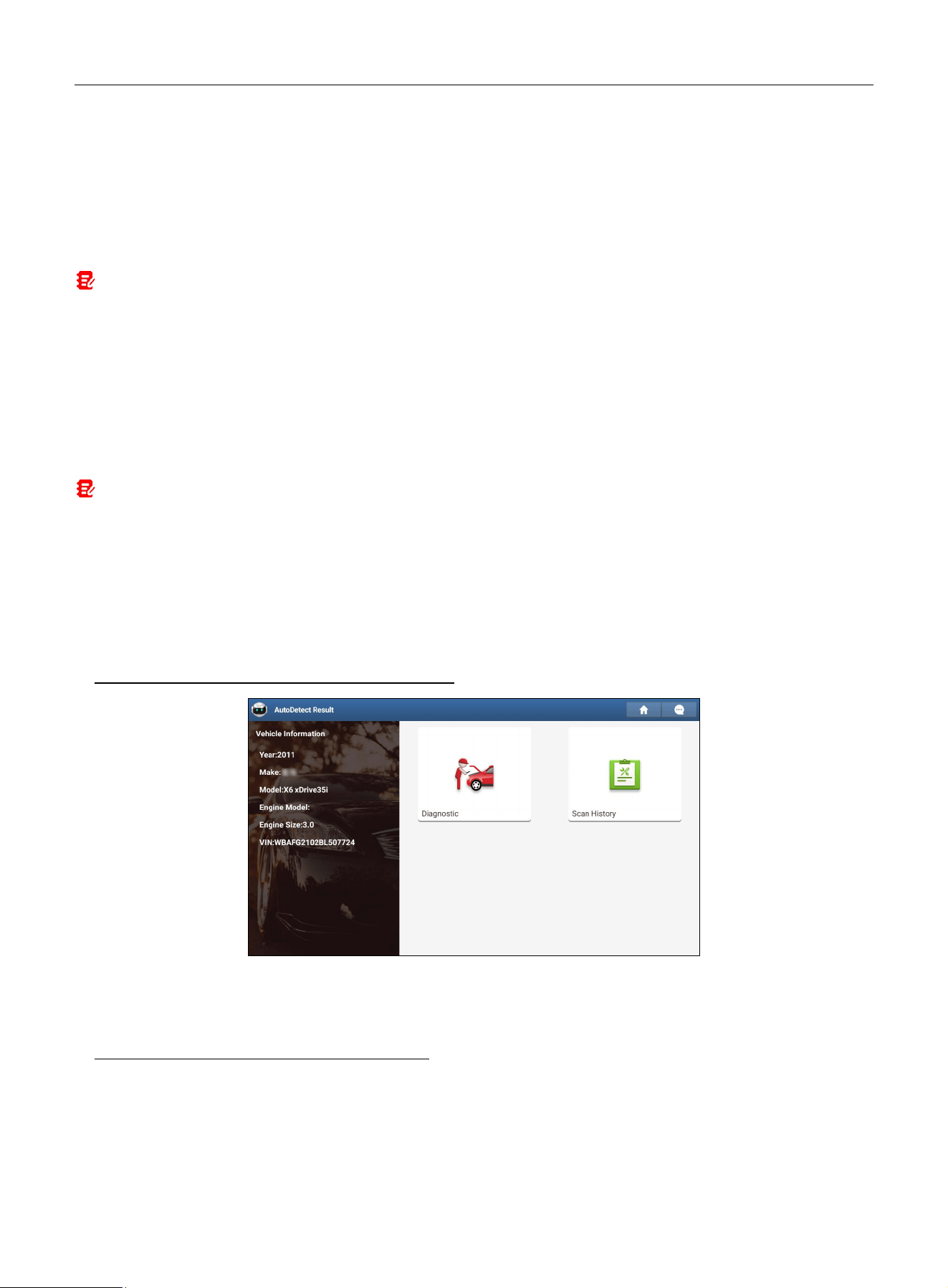
on the Job menu screen to start reading the vehicle VIN.
A. If the VIN can be found in the remote server database, the following screen will appear:
• Tap Diagnostic to start a new diagnostic session.
• Tap Scan History to view its historical repair record. If records exist, it will be listed on the screen in chronological
order. If no records exist, the screen will display No Record.
B.
If the scan tool fails to retrieve the VIN information, it will automatically enter Local Diagnose mode. See Chapter 4.2
for details.
4.2 Diagnose (Manual Select)
This function allows you to diagnose the electronic control systems of individual vehicle models by manually executing
menu-driven commands.
LAUNCH
13
Tap Diagnose to enter the vehicle selection page.
Two approaches are provided for you to access vehicle diagnostic software. Choose either of the following ways:
1. VINSCAN Service operations are the same as in Intelligent Diagnose. Refer to Chapter 4.1.2 for details.
2. Tap the corresponding diagnostic software logo, and then follow on-screen instructions to access the software.
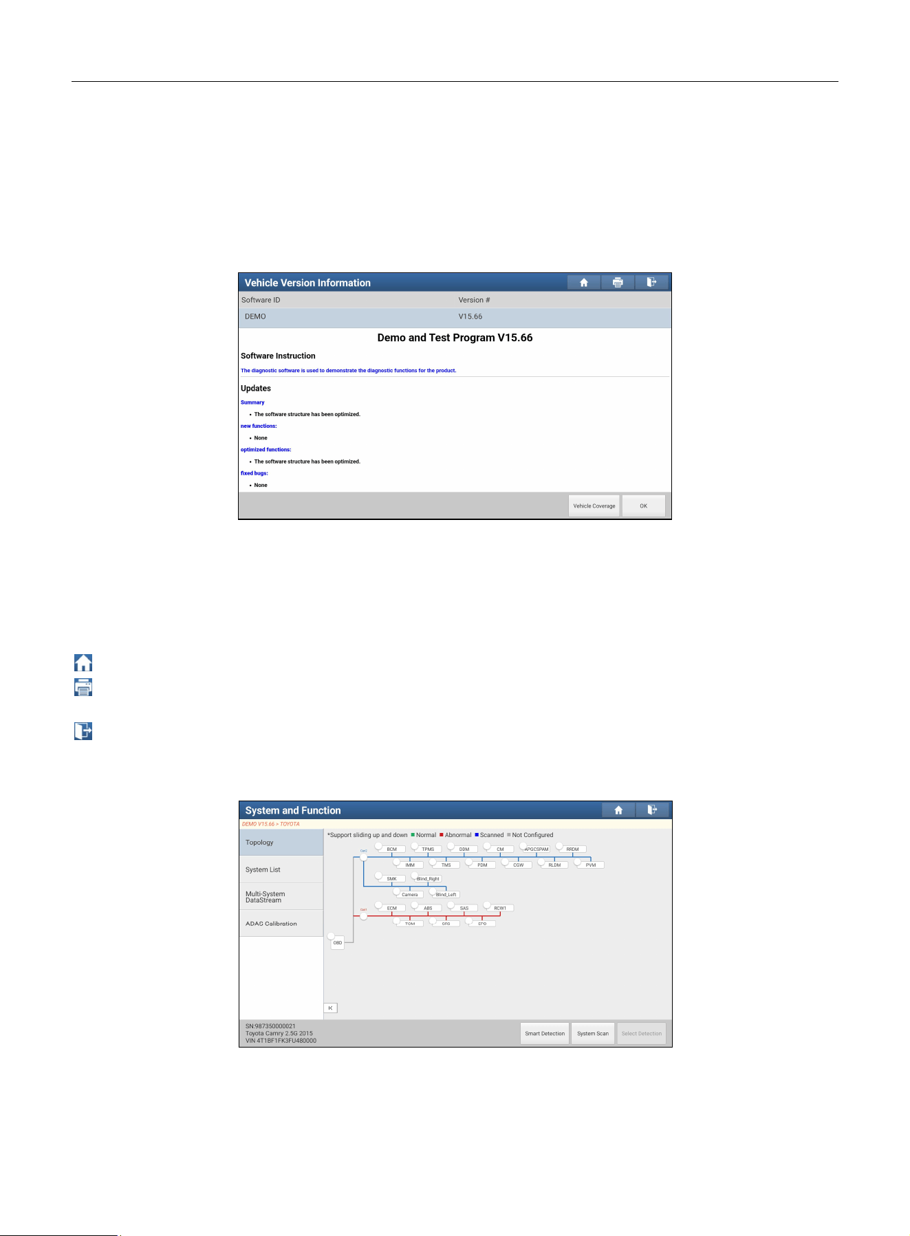
Take Demo (Version 15.66) as an example to demonstrate vehicle diagnosis.
1). Select diagnostic software version: Tap the DEMO to go to Step 2.
On-screen Buttons:
Vehicle Coverage: View vehicle models supported by the current diagnostic software.
OK: Tap to proceed to the next step.
The diagnostics toolbar contains several function buttons and remains visible at the top of the vehicle diagnostic screen
throughout the whole diagnostic session. Brief descriptions are listed below:
Home: Return to the home screen.
Print: Print selected screenshots via an external printer. The printer must be configured separately. For printer
setup details, refer to Chapter 9.5.4.
Exit: Exit the diagnostic application.
2). Select vehicle model. TOYOTA is used here as an example.
3). Select the desired test item to continue.
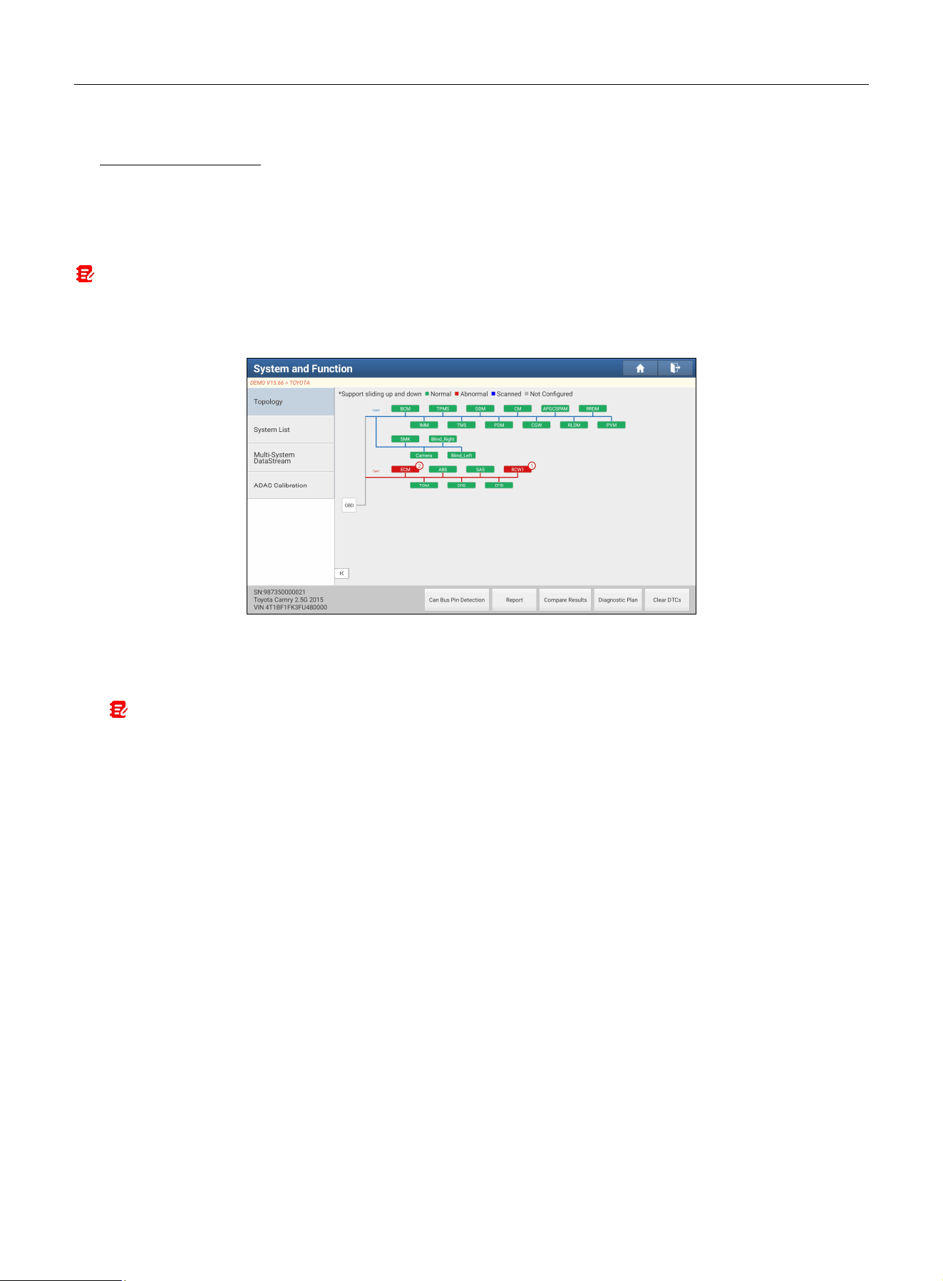
Topology: Display all available vehicle systems in a topology structure.
System List: Display all available vehicle systems in the form of a list.
Multi-System Data Stream: Quickly preview target data streams of multiple systems in thumbnail view.
ADAS Calibration: Perform ADAS calibration. It is extracted from the system list as a dedicated module for quick
LAUNCH
14
access.
While in Topology mode, different highlight bars indicate different detection statuses.
On-screen Buttons:
Smart Detection: Quickly access all electronic control units of the vehicle and generate a detailed vehicle health report.
The malfunctioning tested systems are displayed in red with a DTC count indicator, and the systems functioning
properly are displayed in green.
Note: Diagnostic Trouble Codes or Fault Codes can be used to identify which engine systems or components that are
malfunctioning. Never replace a part based only on the DTC definition. Retrieving and using DTCs for troubleshooting vehicle
operation is only one part of an overall diagnostic strategy. Always follow testing procedures, instructions, and flowcharts in
vehicle’s service manual to confirm the locations of the problem.
• Can Bus Pin Detection: Detect the voltage of the passenger vehicle OBD II diagnostic socket pins and the
supported protocol types to help technicians evaluate the OBD II diagnostic interface.
• Report: Save current data in text format. All reports are saved in User Info -> My Report -> Health Reports.
Notes:
1. Diagnostic reports are classified into three categories: Pre-Repair report, Post-Repair report and Diagnostic Scan. To
facilitate comparison of pre-repair and post-repair reports and obtain accurate test result, ensure you save the correct type
of diagnostic report.
2. By default, workshop information is blank. You can configure it in
Other Modules -> Settings -> Shop Information
.
Once configured, the information will be automatically included every time you save a diagnostic report. All vehicle and
workshop information will be appended as tags on the diagnostic report, allowing you to easily retrieve the desired report
using the Filter function of Diagnostic Report.
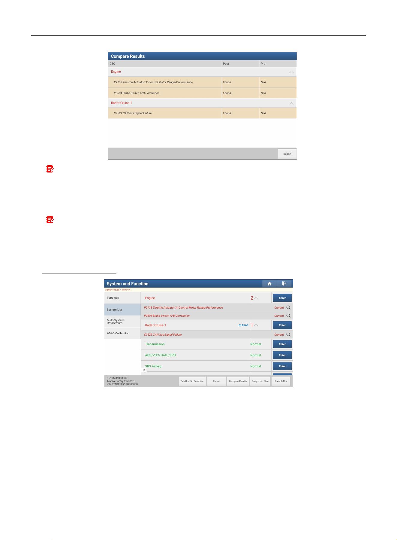
• Compare Results: Tap to select the pre-repair report to compare. By comparing pre-repair and post-repair reports,
you can easily identify which DTCs are cleared and which remain unfixed.
LAUNCH
15
Note: Before performing this function, ensure: 1) A pre-repair report for the current vehicle has been saved; and 2)
Repairs and service have been completed and DTCs cleared after the pre-repair report was generated. Otherwise, no
meaningful difference will appear.
• Diagnostic Plan: Provide a diagnostic plan and repair solutions for detected DTCs.
• Clear DTCs: Clear existing diagnostic trouble codes.
Note: Clearing DTCs does not fix the problem(s) that caused the code(s) to be set. If proper repairs to correct the
problem that caused the code(s) to be set are not made, the code(s) will appear again and the check engine light will
illuminate as soon as the problem that causes the DTC to set manifests itself.
System Scan: Scan which systems are installed on the vehicle.
Select Detection: Manually select a specific system to start scanning.
While in System List mode, the following screen will appear.
• Enter: Select a system and tap this button to enter the diagnostic function selection screen.
LAUNCH
16
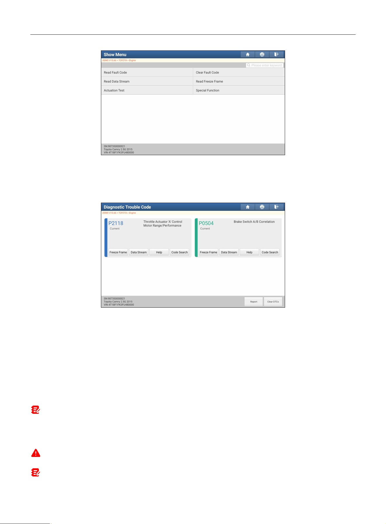
In general, diagnostic functions vary by vehicle model. It mainly includes the following options:
A. Read Fault Code
This function can read detailed DTC information stored in the ECU memory, allowing quick identification of the vehicle
fault cause.
On-screen Buttons:
Freeze Frame: View snapshot of critical parameter values when the DTC was set.
Help: View help information.
Code Search: Search online for additional information about the current DTC.
Report: Save current data in text format. All reports are saved in User Info -> My Report -> Health Reports.
Clear DTCs: Clear existing diagnostic trouble codes.
B. Clear Fault Code
This function allows you to erase codes from the vehicle after reading the retrieved codes and completing necessary
repairs. Before operation, ensure the vehicle ignition is in the ON position with the engine off.
Note: After clearing, always re-retrieve trouble codes. If there are still some trouble codes in the system, troubleshoot the
code using the factory diagnosis guide, then clear the code and recheck.
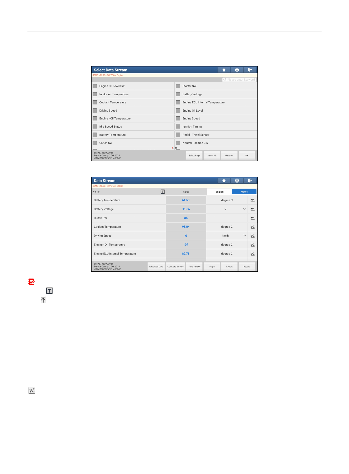
C. Read Data Stream
This function retrieves and displays live data and parameters from the vehicle’s ECU.
Caution: If you must drive the vehicle in order to perform a troubleshooting procedure, ALWAYS have a second person assist
you. Trying to drive and operate the scan tool at the same time is dangerous, and could cause a serious traffic accident.
Note: The real-time (Live Data) vehicle operating information (values/status) that the on-board computer supplies to the tool
LAUNCH
17
for each sensor, actuator, switch, etc. is called Parameter Identification Data (PID).
Tap Read Data Stream, the following screen will appear:
After selecting the desired items, tap OK to enter the data stream reading page.
Notes:
1.
Tap to set display style for each selected item.
•
(Push-to-top icon): Pins the item to the top of the list. To remove it from the top of the list, just tap it again.
•
B
: Displays the item in Bold.
•
A
: Displays the item in Red.
2.
Tap
English
or
Metric
to switch measurement units.
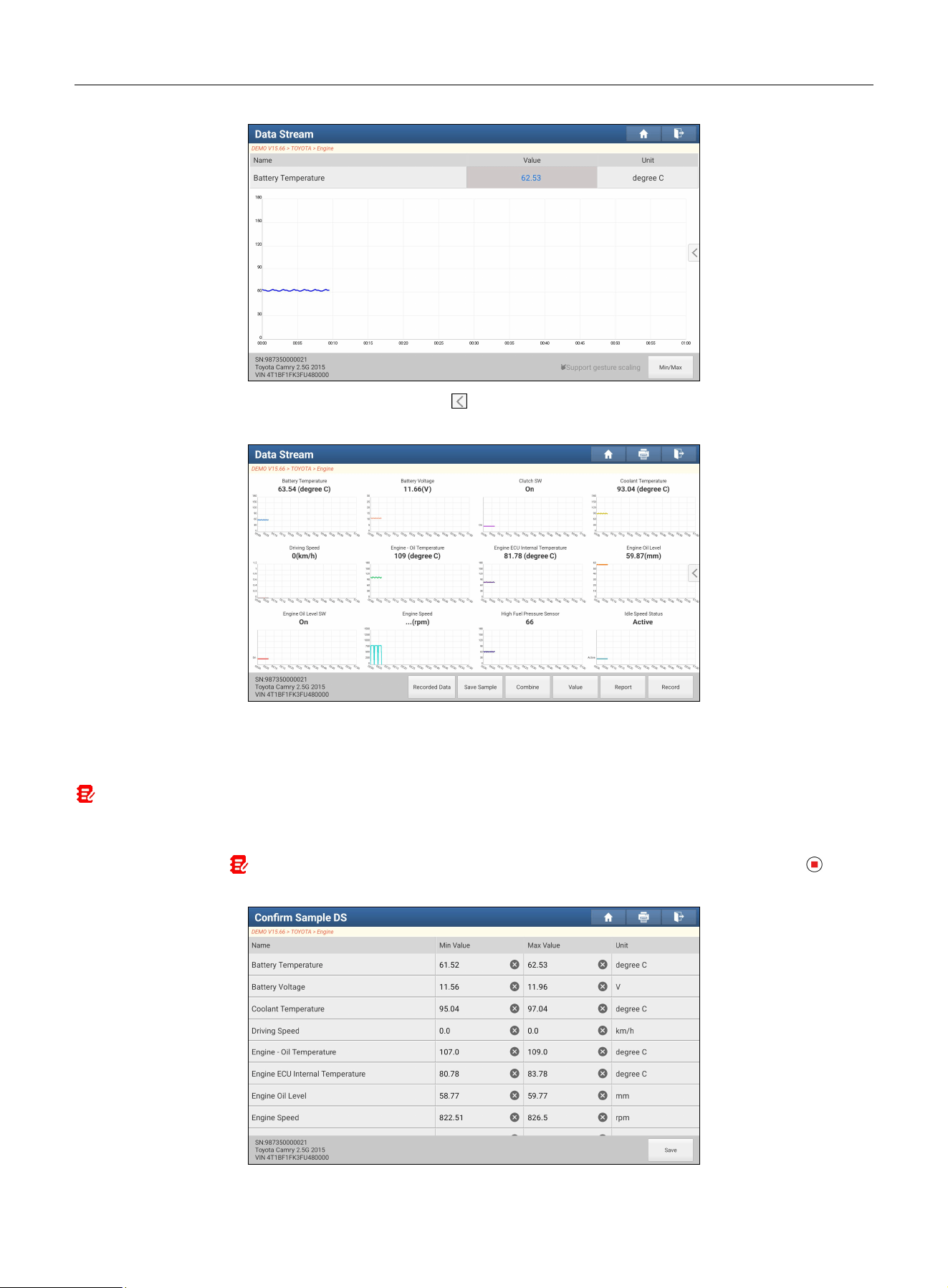
Three display modes are available for data viewing, allowing you to view various types of parameters in the most
suitable way.
Value: Displays parameters as texts in list format (default mode).
Graph: Displays parameters in waveform graphs.
Combine: Used for graph overlay and data comparison.
In this case, different items are marked in different colors.
On-screen Buttons:
:
View live waveform.
LAUNCH
18
Graph: View waveforms of selected data streams. Tap on the edge of the screen to customize target data streams
for displaying.
Recorded Data: Quickly access the Recorded Data, which collects all recorded data stream files.
Compare Sample: Load a saved sample data stream file, the values you customized and saved during data stream
sampling will be imported into the Standard Range column for your comparison.
Note: Before using this function, you have to sample and save data stream values as a sample file.
Save Sample: Customize standard range for live data stream items and save as a sample file. Each time you run the
data stream items, you can load the corresponding sample data for comparative analysis.
Tap to start recording
( Note: Only data stream items with units are recorded)
. Once recording is complete, tap to edit
values.

LAUNCH
19
After modifying values, tap Save to confirm. All sample files are stored in Diagnostic Widget -> Data Stream Sample.
Report: Save current data in text format. All reports are saved in User Info -> My Report -> Health Reports.
Record: Start recording diagnostic data. Recorded live data can serve as valuable information to help you in
troubleshooting of vehicle problems. All recorded files are stored in User Info -> My Report -> Recorded Data.
D. Read Freeze Frame
This function takes the snapshot of the operating conditions when a vehicle fault occurred.
E. Actuation Test
This function is used to access vehicle-specific subsystem and component tests. Available test vary by vehicle
manufacturer, year, and model.
During the actuation test, the tool sends commands to the ECU to drive actuators, and then verifies the integrity of the
system or components by reading ECU data or monitoring actuator operation (e.g., switching an injector between two
states).
F. Special Functions
This function provides coding, reset, relearn and other service functions, to help vehicles restore to functional status
after repair or component replacement. Available tests vary by vehicle manufacturer, year, and model.
4.3 Remote Diagnose
4.3.1 SmartLink Super Remote Diagnosis
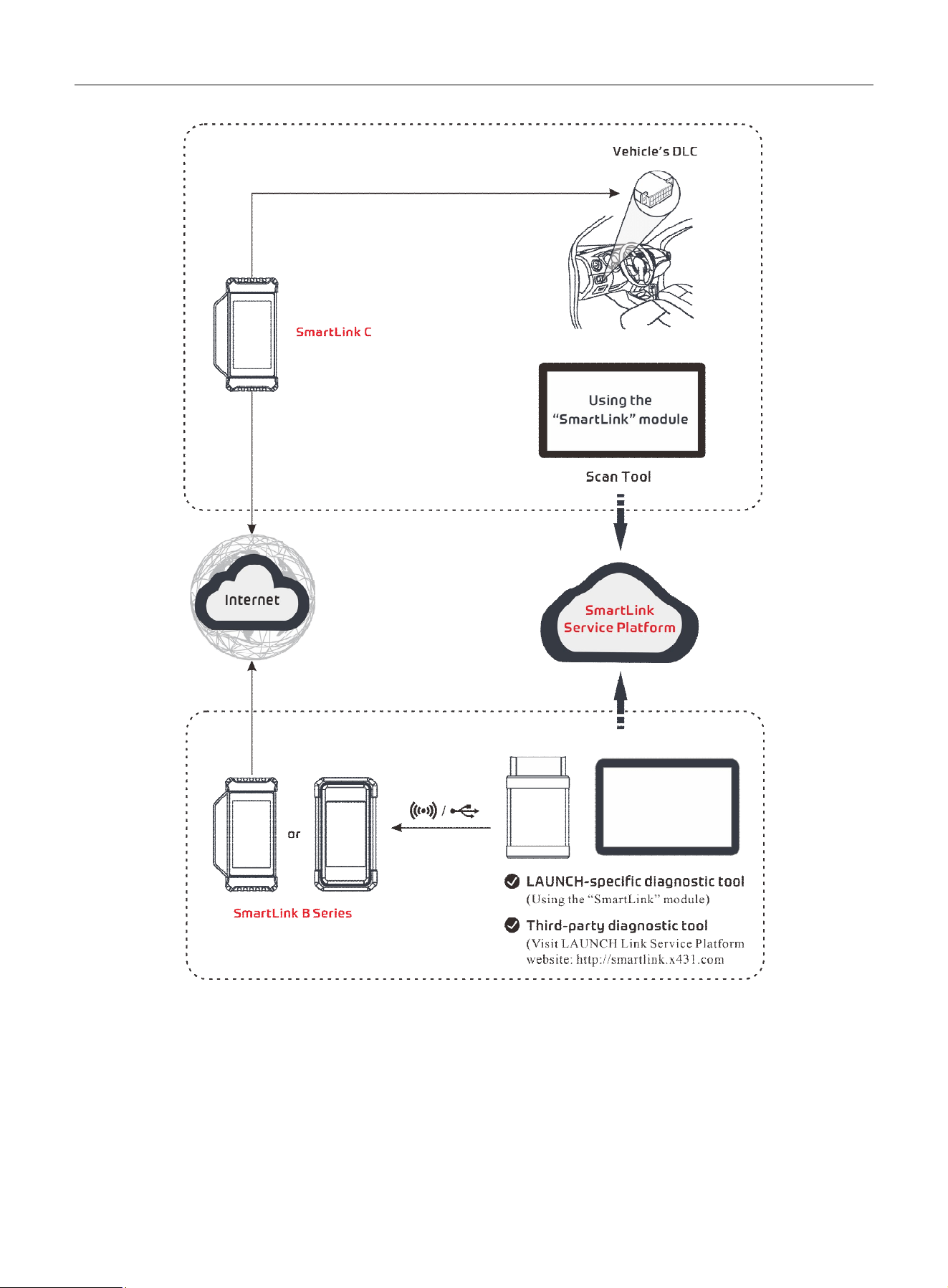
SmartLink is a newly developed powerful service system dedicated to remote vehicle diagnosis and service. In the
SmartLink ecosystem, if a technician (SmartLink C) does not have time to puzzle through a tough vehicle problem, they
can seek a trusted second opinion or additional expertise on various vehicle issues from remote master technicians or
repair shops (SmartLink B). SmartLink B enables the shop owner to greatly improve customer retention and boost shop
revenue by providing professional technical assistance service.
It mainly consists of the following parts:
LAUNCH
20
• SmartLink Service Platform – It can be accessed via the SmartLink module of the scan tool. There are two
modules available on the service platform: Common User (for SmartLink C) and Service Provider (for SmartLink
B).
• SmartLink C (Customer) - SmartLink Service Subscriber. In the SmartLink system, the SmartLink C needs to
perform the following operations:
1). Launch Service Link Platform: Bind SmartLink C dongles and submit remote repair orders.
2). SmartLink C Dongle: Connect to the vehicle’s DLC port to collect vehicle data and send it to the remote SmartLink
B.
LAUNCH
21
It supports remote diagnostic services for vehicles that meet CAN2.0/CANFD/J2534 vehicle diagnostic standards.
• SmartLink B (Business) - SmartLink Service Provider. In the SmartLink system, the SmartLink B needs to
perform the following operations:
1). Launch Service Link Platform: Bind SmartLink B dongle and accept orders from SmartLink C.
• If the SmartLink B dongle works with the LAUNCH-specific scan tool equipped with SmartLink module, tap
SmartLink to add the SmartLink B device and accept orders on the scan tool.
• If the SmartLink B dongle works with the third-party scan tool, open a browser and visit SmartLink Service Platform
website http://smartlink.x431.com (web client) to add the SmartLink B device and accept orders in the browser.
2). SmartLink B Dongle: After accepting orders, it can work with the compatible scan tool to perform diagnosis on the
vehicle connected to the SmartLink C dongle.
For more detailed operations, refer to the User Manual integrated in the SmartLink Platform.
4.3.2 X431 Remote Diagnosis
This function helps repair shops or technicians launch instant messaging and remote diagnosis, making repairs faster
and more efficient.
• The scan tool and other LAUNCH-specific scan tools equipped with this module.
• The scan tool and PC client technician (based on web-based remote diagnosis platform http://remote.x431.com/).
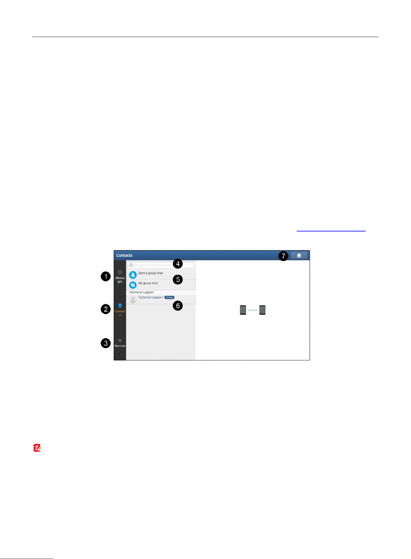
Tap Remote Diagnose -> X431 Remote Diagnosis to enter the following screen.
1. Messages tab
Tap to display a list of messages you are involved in. When a new message arrives, a red dot will appear on the upper
right corner of the tab.
2. Contacts tab
Tap to show your friend or partner list. If no friends have been added, only Technical Support is displayed by default.
To search for a desired partner, enter the partner’s username or scan tool serial number in the search bar.
You can also start and manage group chats.
Note: Partners must be users who have registered their LAUNCH-specific scan tools. They may be workshops, technicians, or
golo users.
3. Remote tab
This function allows you to request remote assistance from a PC client technician.
4. Search bar
Directly input the registered username of the tool to start searching, then tap the desired result to add it to your friend
list.
LAUNCH
22
5. Group Chat operation
Used to start and manage group chats.
6. Contacts list
Displays a list of friends. If no friends list has been created, only Technical Support is displayed by default.
7. Home button
Navigates to the Job Menu screen.
1. Remote Diagnosis with Other Specific Scan Tools
This function allows you to initiate remote diagnosis with other LAUNCH-specific scan tools equipped with this module.
To launch remote diagnosis with a partner not in your friend list
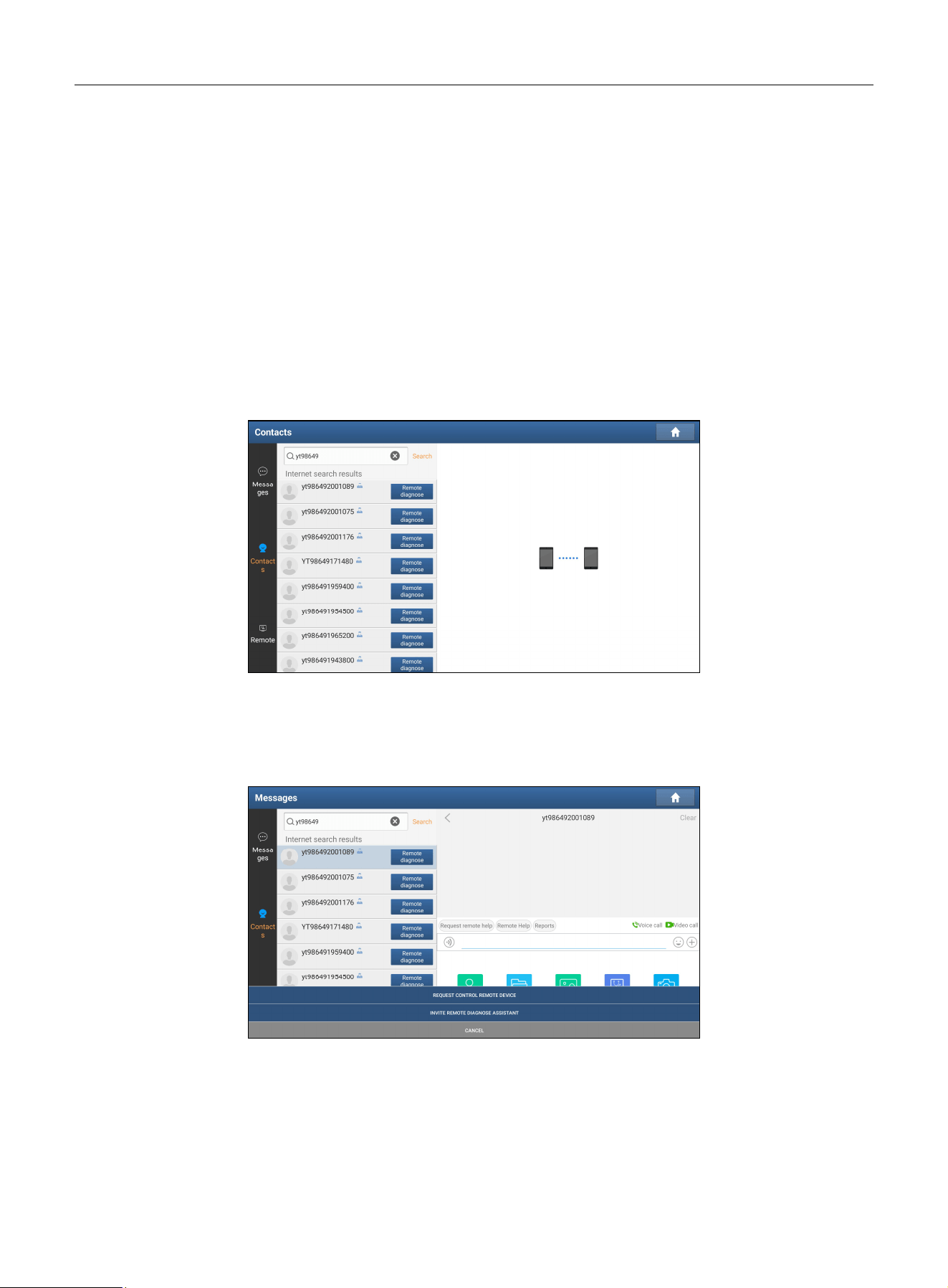
1. Tap Contacts. In the search bar, input the partner’s username or scan tool serial number, then tap Search.
2. When the search is complete, the following screen will appear:
3. On this screen, you can directly tap Remote Diagnose next to the username to launch remote diagnosis, or tap the
technician’s avatar to proceed.
When you directly tap Remote Diagnose, follow the steps below:
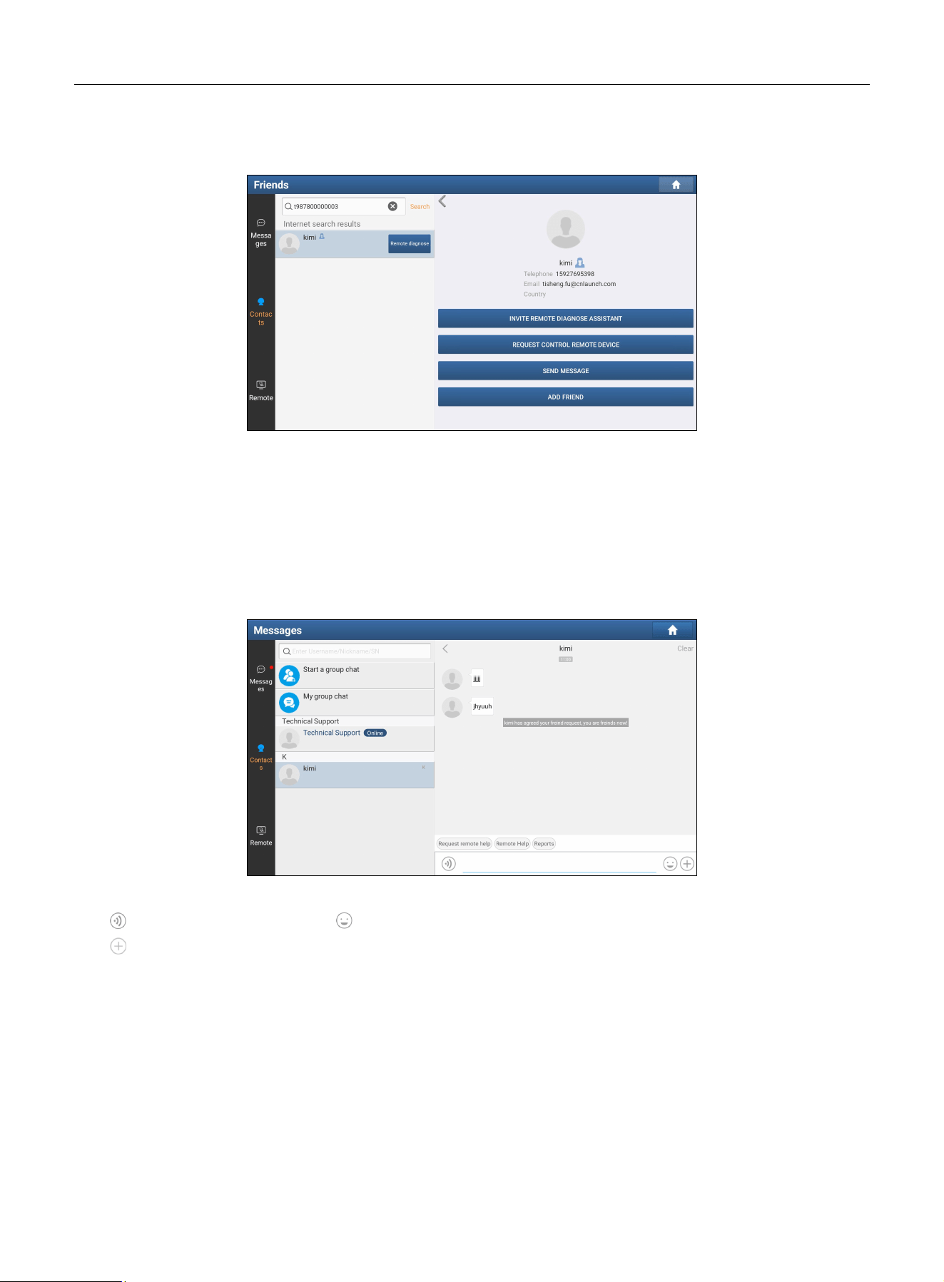
1) Tap Remote Diagnose, and the following drop-down menu will appear:
2) Tap REQUEST CONTROL REMOTE DEVICE or INVITE REMOTE DIAGNOSE ASSISTANT.
3) Choose the desired diagnostic software (this step applies only to the INVITE REMOTE DIAGNOSE ASSISTANT).
4) Wait for the partner’s confirmation.
5) The connection starts after the request is accepted.
6) Begin diagnosis and generate a remote diagnostic report.
LAUNCH
23
When you tap the technician’s avatar, follow the steps below:
1) Tap the desired technician’s avatar, the following screen will appear:
2) Tap REQUEST CONTROL REMOTE DEVICE or INVITE REMOTE DIAGNOSE ASSISTANT to request or provide
remote assistance.
You can tap ADD FRIEND to send a friend request. After the partner accepted the request, a beep will sound, and the
partner will be automatically added to the Contacts tab.
If necessary, you can also tap SEND MESSAGE to start instant messaging.
To launch remote diagnosis with a partner in your friend list
Tap Contacts, select a desired partner; the following screen will appear:
Tap the input field and use the on-screen keyboard to send messages.
Tap
to send voice messages. Tap
to send emojis.
Tap
to open the following function options:
• File: Select diagnostic reports or local files to send.
• Picture: Select screenshots or images to send.
• Remote Diagnose: Start a remote diagnosis session.
• Camera: Activate the camera to take photos.
You can also tap the avatar of the desired partner to request control of remote device, invite remote diagnose assistant,
or send a message.
2. Remote Diagnosis with PC Client Technician
This function allows you to request remote control or provide remote assistance via the web-based remote diagnosis
platform.

LAUNCH
24
1. Tap Remote, the following screen will appear:
2. Slide the switch to ON so that the remote technician can control your device using the web-based remote diagnosis
platform.
3. Instruct the remote technician to log in to the remote diagnosis platform http://remote.x431.com.
Note: Before starting remote diagnosis, ensure that the device is properly connected to the vehicle and the network
connection is stable.
4. After the technician successfully logs in to the platform, the following screen will appear.
5. The technician can enter your scan tool serial number and start remote diagnosis. Your device is now remotely
controlled by the technician.
LAUNCH
25
During remote diagnosis, note the followings:
1) It is recommended that you do not perform any operations.
2) The partner is not allowed to save any diagnostic reports or records on your tool.
Once the session is complete, a remote diagnostic report will be generated automatically.
4.4 EV Diagnose
This function applies only to the new energy vehicles. It supports vehicle diagnosis, battery pack detection, and certain
service functions.
Note: This function requires New Energy Vehicle Diagnosis Add-on Kit (optional), which can be purchased from an
authorized dealer.
4.4.1 Vehicle Diagnosis
This function is designed for manually diagnosing the electronic control systems of a single new energy vehicle. The
operation is the same as in Local Diagnose. Refer to Chapter 4.2 for details.
4.4.2 Battery Pack Detection
This function can detect the battery pack of new energy vehicles. Three methods are provided:
• via BMS (Battery Management System) AUTODETECT program
• via vehicle maker
• via battery brand manufacturer
The following example uses BMS AUTODETECT to demonstrate battery pack detection:
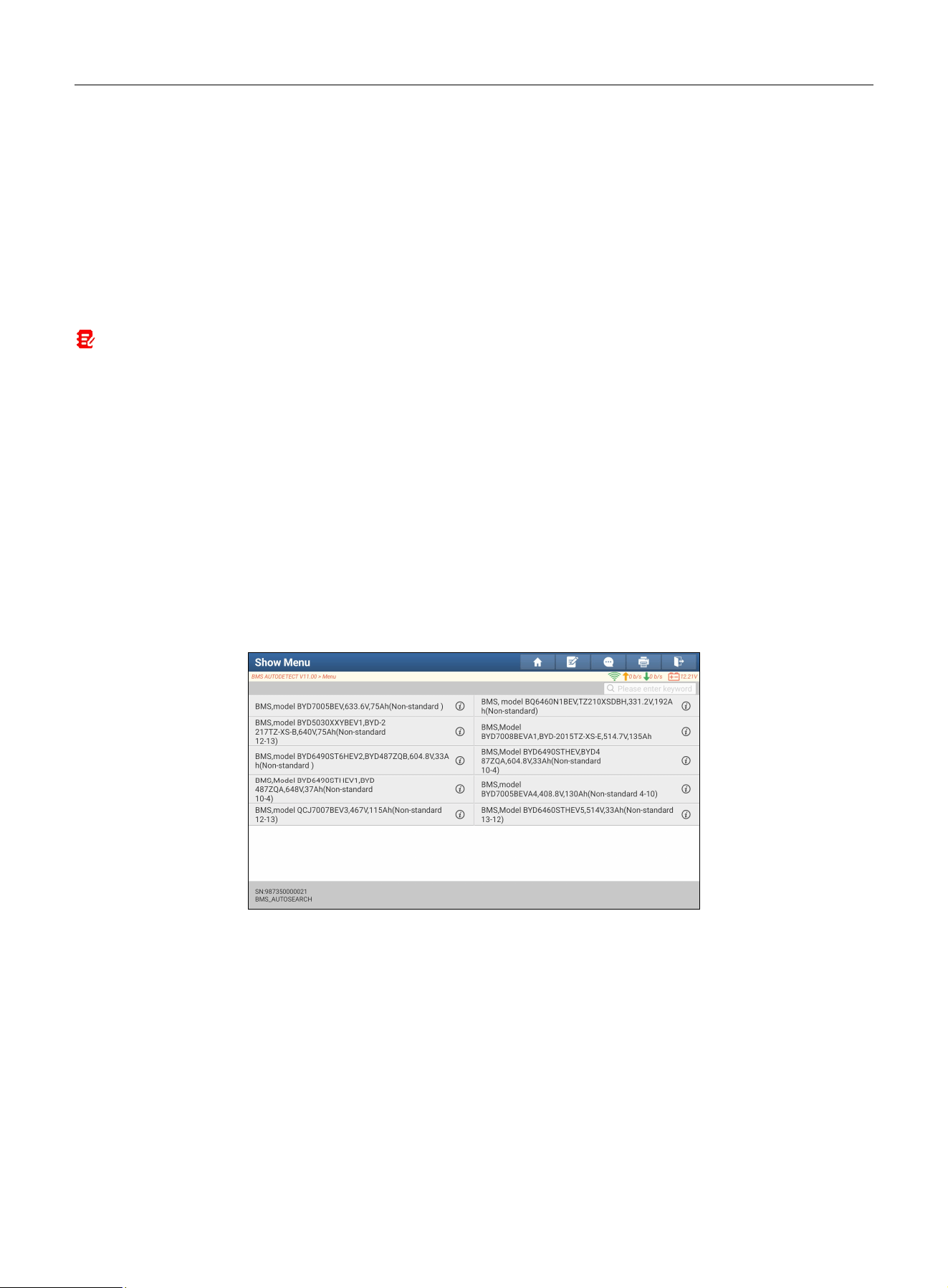
1. Tap BMS AUTODETECT, the system will start detecting the BMS.
2. Select the desired BMS model to enter the following screen.
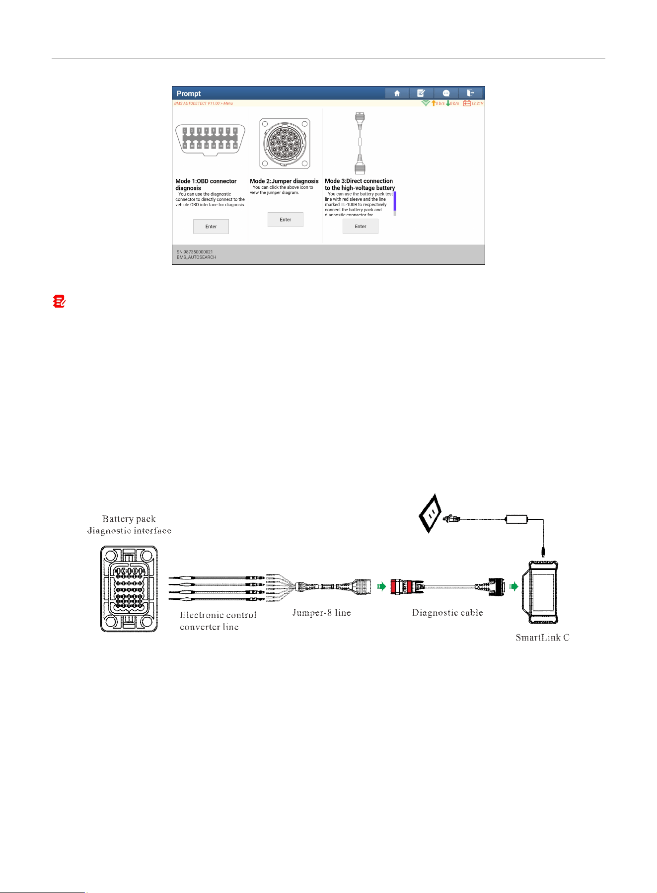
LAUNCH
26
3. Select the preferred detection mode and start the detection until the system displays the test result.
Note: Available detection modes vary with the vehicle model/battery brand. The following modes are generally provided:
Mode 1:
Via OBD diagnostic interface
Refer to Chapter 3.1 for connection methods.
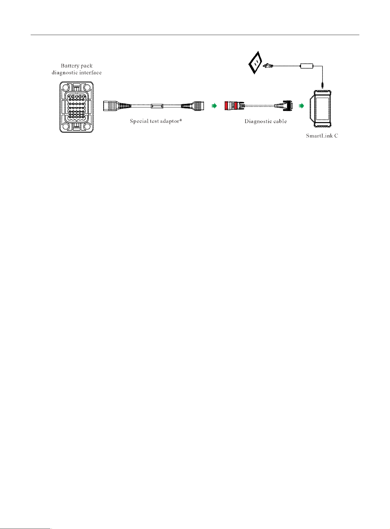
Mode 2: Via communication interface of the battery pack
Choose either of the following connection methods:
1. Using Jumper line & corresponding electronic control converter line
1. Connect one end of the diagnostic cable to the DB-15 diagnostic connector of the SmartLink C device, and the other end to OBD-16
connector of the Jumper-8 line.
2. Tap the icon shown on the screen to view detailed connection prompts. Follow the on-screen instructions to connect the electronic
control converter line, battery pack communication interface and Jumper-8 line.
3. Connect the SmartLink C device to an external power source.
2. Using Specific test adaptor
1. Connect one end of the diagnostic cable to the DB-15 diagnostic connector of the SmartLink C device, and the other end to OBD-16
connector of the specific test adaptor.
2. Plug the other end of the specific test adaptor into the battery pack communication interface.
3. Connect the SmartLink C device to an external power source.
LAUNCH
27
The specific battery pack test adaptor varies by vehicle model/battery brand and the screen will prompt the corresponding adaptor model
for the current test.
4.5 Service Function
This function provides coding, reset, relearn, and other service functions to help vehicles get back to functional status
after repair or component replacement. Available tests vary by vehicle manufacturer, year, and model.
Due to continuous product improvements, available service functions are subject to change without prior written notice.
To access more service functions, it is recommended to check for updates regularly.
4.6 Feedback
If you encounter unsolved problems during diagnosis, you can send your last 20 test records to us using the Feedback
function for timely technical support.
Tap Service on the Job Menu screen, then tap Feedback. Three options are available:
1. Feedback: Displays the list of the tested vehicle models.
2. History: Views all diagnostic feedback records and check their status.
3. Offline list: Displays all diagnostic feedback logs that failed to submit due to network issues. Failed logs will be
queued and automatically re-uploaded once a stable network connection is restored.
Our technical support team will process your feedback as soon as possible.
LAUNCH
28
5 Software Update
This module enables you to update the diagnostic software & App and frequently used software.
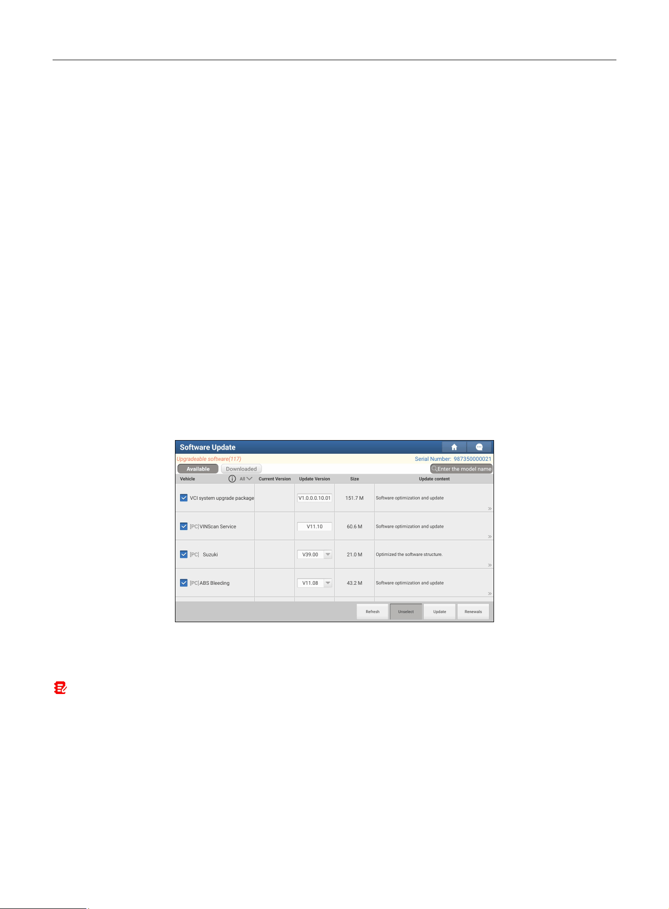
5.1 Update Diagnostic Software & APP
Go to Software Update on the Job Menu and tap the Downloaded tab.
The Available tab displays a list of software that can be updated. Under it, all software is divided into three categories:
• Common software: Mainly includes common apps associated with the diagnostic application. The software of this
kind always appears at the top of the list and can be manually deselected (excluding system apps such as firmware
and ECU Aid).
• Frequently used vehicle software: Refers to frequently used diagnostic software, including vehicle diagnostic
software and reset software. It is generally displayed following the Common software list.
• Other vehicle software: Refers to diagnostic software that is rarely or never used. It is generally displayed following
the Frequently used software list.
1). If the user does not download any diagnostic software during registration, all diagnostic software is selected by
default. Tap Update to start downloading.
2). If the user downloaded all/some vehicle software during registration and had it serviced for a long period of time,
only frequently used software is selected. Tap Update to start downloading. Other rarely used vehicle software will
also be listed under the Available tab, but it is not selected at default.
To download specific frequently used software, check the box next to the vehicle model. Tap Update to start
downloading.
Once the download is complete, the software packages will be installed automatically.
Note: Several types of vehicle software are available: [Automotive] – Passenger Cars, [HD] – Heavy-Duty, [EV] – Electric
Vehicle, [IMMO] – Immobilizer software, and All. Users can download all software or software of the same type as needed.
5.2 Update Frequently Used software
If the user only intends to update the frequently used software, go to Software Update and tap the Downloaded tab.
Tap Update to start downloading. Once the download is complete, the software packages will be installed
automatically.

LAUNCH
29
5.3 Renew Subscription
If the software subscription is due or has expired, the system will prompt you to renew your subscription.
Tap Renewal on the bottom of the screen to enter the Mall to renew the subscription
.

LAUNCH
30
6 Toolbox
This function includes the following add-on modules: Four-Wheel Aligner, TPMS, ADAS, Oscilloscope, Sensor
Simulator, BST360 Battery Tester, Immobilizer programmer, Videoscope, Current Clamp, Multimeter, Insulation Tester,
Key Programmer, and more.
Each module consists of two parts: hardware and a companion app. These apps cannot function properly on the tool,
which need to work with specific compatible hardware (sold separately). For detailed operations, refer to the User
Manual of each module.
6.1 Battery Equalizer
This module is suitable for testing and maintaining various new energy battery packs (including traction batteries and
energy storage batteries). It supports high-current rapid charging and discharging at the battery pack level, efficiently
adjusting the overall voltage of the battery pack to the target state. It needs to work with the specific EVM324 device
(sold separately).
For more details, refer to the User Manual included with the module.
6.2 Battery Charger & Discharger
This module is suitable for testing and maintaining multiple types of new energy battery packs (including traction
batteries and energy storage batteries). It supports independent balancing control for each connected cell, allowing
precise adjustment of individual cells to a uniform voltage level based on user-defined target voltages. It needs to work
with the specific EVM324 device (sold separately).
For more details, refer to the User Manual included with the module.
6.3 TPMS
This module allows you to configure the tool as TPMS activation & diagnostic tool, which provides the ability to trigger
TPMS sensors, program TPMS sensors, perform the relearning procedures. It needs to work with a compatible TSGUN
device (sold separately).
For more details, refer to the User Manual included with the module.
6.4 ADAS (Calibration)
This module enables you to effectively and accurately calibrate a wide range of camera- and radar-based driver
assistance systems, e.g., the front camera for the lane departure warning system, the radar sensor for ACC (Adaptive
Cruise Control) or the camera for adaptive headlights. It needs to work with a specific ADAS calibration tool (sold
separately).
For more details, refer to the User Manual included with the module.
6.5 Oscilloscope
This module helps auto repair technicians quickly diagnose faults in automotive electronic equipment and wiring. It
needs to work with a specific Scopebox (sold separately).
For more details, refer to the User Manual included with the module.

LAUNCH
31
6.6 Sensor Simulator
This module is specially designed to quickly and conveniently diagnose and simulate vehicle sensor faults. It needs to
work with a compatible S2-2 Sensorbox (sold separately).
For more details, refer to the User Manual included with the module.
6.7 Videoscope
This module allows you to inspect unseen parts of the engine, fuel tank, braking system, etc. It needs to work with a
compatible Videoscope (sold separately).
For more details, refer to the User Manual included with the module.
6.8 BST360 (Battery Tester)
This module makes battery testing faster and easier. It needs to work with a specific Bluetooth battery tester (sold
separately).
For more details, refer to the User Manual included with the module.
6.9 Multimeter
This module allows you to measure physical parameters such as voltage, resistance, frequency etc. It utilizes the same
hardware as the EM101N.
For more details, refer to the User Manual included with the EM101N.
6.10 Current Clamp
This module allows you to perform AC/DC current tests and DC voltage tests for traditional fuel vehicles and new
energy vehicles. It needs to work with a compatible current clamp (sold separately).
For more details, refer to the User Manual included with the module.
6.11 Insulation Tester
The module allows you to measure insulation resistance, voltage and other parameters. It is suitable for users
performing on-site measurement and overhaul of power equipment and supply lines. It needs to work with a compatible
insulation tester (sold separately).
For more details, refer to the User Manual included with the module.
6.12 Immobilizer Programmer
This module allows you to perform the read/write function for vehicle keys, EEPROM, MCU, and the EEPROM/FLASH
of vehicle engine and gearbox ECUs. It needs to work with a specific immobilizer programmer (sold separately).
For more details, refer to the User Manual included with the module.
6.13 Key Programmer
This module can identify car key chips and generate various types of chip models from super remotes, read the remote
control frequency of car keys, and generate remote control devices for different car models from various super remotes.
It needs to work with a compatible key programmer (sold separately).
For more details, refer to the User Manual included with the module.

LAUNCH
32
7 Diagnosis Kit
7.1 Vehicle Coverage
Use this function to check which vehicle models are supported on the tool.
7.2 CAN Bus Pin Detection
This function allows you to detect the voltage of the OBD diagnostic socket pins and the supported protocol types for
vehicles, helping technicians evaluate the OBD diagnostic interface.
7.3 CANScope
This function can monitor vehicle CANBUS data and display it visually on the screen. Moreover it can also detect issues
existed in the CAN data to assist with analyzing fault causes.
7.4 Diagnostic Software Clear
This function allows you to hide or clear infrequently used diagnostic software.
Note: Removing software may delete it completely from the tool. If some software is unused and the tool is low on storage
space, you can use this feature to remove it. To re-download it, go to
Software Update
->
Available
.
7.5 Firmware Fix
Use this function to upgrade and repair the VCI firmware/system. During the repair process, do not disconnect power or
switch to other interfaces.
7.6 Data Stream Sample
This function allows you to manage recorded data stream sample files.
7.7 Battery Voltage
This function checks the vehicle’s battery to ensure the system operates within acceptable limits.
7.8 Reset MSVIN
This function can decode VIN information from all ECUs installed on the test vehicle and output all inconsistent VINs.
7.9 Diagnostic History
This function provides convenient access to previously tested vehicles, allowing users to resume from the last operation
without needing to start anew.
Tap Diagnostic History, all diagnostic records will be listed on the screen in date order.
7.10 Vehicle QR
This function acts as a vehicle QR code scanner and is available in Japan. After scanning the vehicle QR code with this
function, you can access product information, videos, and reviews about the vehicle.

LAUNCH
33
8 User Info
This function allows users to manage personal information and VCIs.
8.1 My Report
This function allows you to view, delete, or share saved reports or recorded data.
Tap My Report, three options are available:
1. Health Reports: Lists files saved from the Read Trouble Code page.
2. Remote Reports: Lists all diagnostic reports generated during remote diagnosis.
3. Recorded Data: Lists all files recorded while reading data streams.
8.2 My VCI
This function allows you to manage all your activated VCIs and activate new VCIs.
If multiple VCIs are activated on this tool, a list of VCIs will be displayed. If you select a VCI belonging to another
account, you must log out and log in with the correct account to continue.
If you skipped the Activate VCI step during product registration, tap Activate VCI to activate a new VCI.
8.3 Profile
This function allows you to view and edit personal information.
8.4 My Order
This function allows you to check the status of all your orders.
8.5 Reset Password
This function allows you to modify your login password.
8.6 My Software
This function allows you to view the software list and expiration dates for current product configurations or purchased
software packages, and manage their renewals.
8.7 VCI Management
This function allows you to set the wireless communication method between the scan tool and VCI. This function is
hidden by default.
If the default Wi-Fi communication between the scan tool and VCI device fails, users may switch to wireless BT
communication instead. Tap My VCI four times consecutively to display the VCI Management option, and then select
Use BT communication mode therein.
8.8 Login/Log out
To log out the current user ID, tap Log Out.
To log in to the system again, tap Login.

LAUNCH
34
9 Other Modules
9.1 License List
This function allows you to activate the SWG function and verify the SWG user authentication on your scan tool.
9.2 My Points
This function is a user point management center. Points are rewards for X-431 users and can be used to deduct cash
when purchasing vehicle software.
9.3 Error Correction
This function allows you to check the review status of interface translations you have modified and submitted.
9.4 Complaint & Suggestion
This function allows you to submit feedback including incorrect or inappropriate interface translations, function failures,
product experience, and member services to help us to make continuous improvements.
9.5 Settings
This function allows you to adjust application settings.
9.5.1 Diagnostic Setup
This function allows you to configure the following items:
1. Units
Set the measurement unit. Metric System and English System are available.
2. System scan includes system version information
Set whether to include system version information when scanning vehicle systems.
3. Automatic detection once connected
Set whether to start automatic VIN detection once the SmartLink C device is properly connected to the vehicle’s DLC.
9.5.2 X Button Customization Settings
This function allows you to customize which function modules are launched quickly when the X button is pressed.
9.5.3 Shop Information
This function enables you to enter your shop information. Once saved, it will be auto-filled in the Add Information box
every time you save a diagnostic report.
9.5.4 Printer Set
This function allows you to establish a wireless connection between the tool and the Wi-Fi printer (sold separately) for
printing operations.
The App is compatible with the LAUNCH Wi-Fi Printer (sold separately) and the System (external printer).
For LAUNCH Wi-Fi printer, refer to the user manual included with the printer to configure it.
For other Wi-Fi printers:
Before printing, make sure that the Wi-Fi printer is powered on and working normally.

LAUNCH
35
Follow the steps below to proceed:
1. Set the default printer to System.
2. Set the WLAN switch to On.
3. Tap the desired Wi-Fi printer hotspot to connect.
4. On the report details page, tap Print or .
5. Touch next to Select a printer to choose the desired Wi-Fi printer from the list.
• If the hotspot is open, the tool will connect directly.
• If encrypted, enter the password (see the printer’s user manual for the default password).
6. The printer is now ready.
7. Alternatively, select Save as PDF to save the diagnostic report as a PDF file for later printing.
9.5.5 Clear Cache
This function allows you to clear the app cache.
Clearing the cache will restart the app.
9.5.6 About
This option allows you to check software version, product manual, service agreement and privacy policy, etc.
9.5.7 Diagnostic Software Auto Update
Use this function to enable or disable automatic software updates.
9.5.8 Device Account Management
This function manages sub-accounts, allowing the tool to be used by different technicians and helping track diagnostic
logs.
Newly added sub-accounts are valid for one year. After expiration, they lose main account privileges. However, the main
account can modify the validity period of the sub-account.
There are two types of sub-accounts: existing accounts and newly created ones. The main account can add or remove
sub-accounts, while sub-accounts can also unbind from the main account.
Tap Device account management, then tap Add technician account:
• If you already have an account, enter the user name and password, then tap Add Immediately to set it as a
sub-account.
• If you do not have an account, tap new technician account to create a sub-account.
After adding a sub-account, you can tap Remove to unbind it from the main account or tap Change to modify its validity
period.
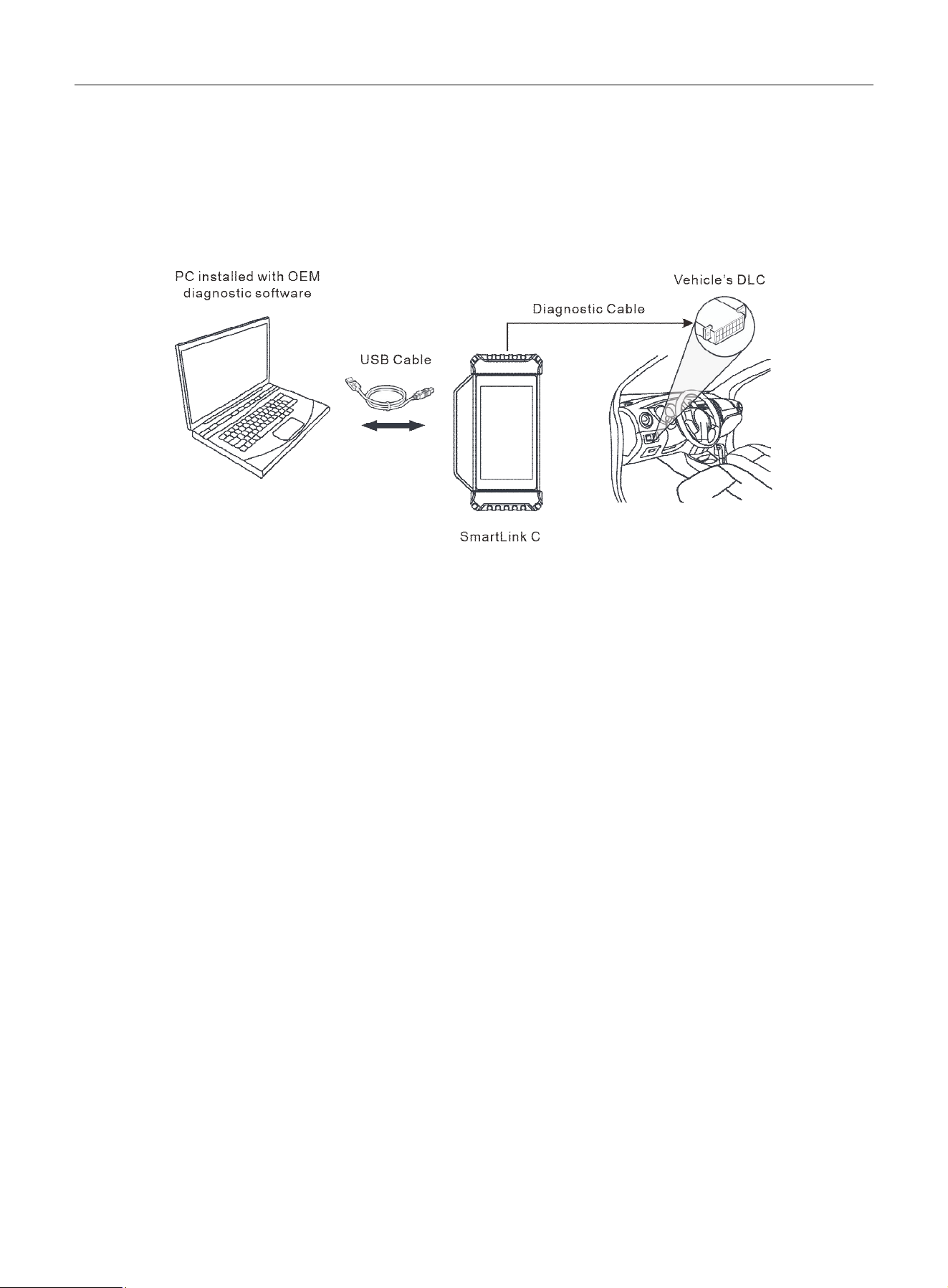
LAUNCH
36
10 J2534 Reprogramming Using SmartLink C
The SmartLink C can also act as a J2534 PassThru device, working with a PC running OEM diagnostic software and
LAUNCH's J2534 tool (available at https://en.cnlaunch.com).

LAUNCH
37
11 FAQs
1. How to save power?
1. Turn off the screen when idle.
2. Set shorter standby time.
3. Lower the brightness of the screen.
4. Turn off WLAN when not needed.
2. Communication error with vehicle ECU?
Please confirm:
1. Whether the VCI is correctly connected.
2. Whether ignition switch is ON.
3. If still faulty, send vehicle year, make, model and VIN number to us using Feedback feature.
3. Failed to enter vehicle ECU system?
Please confirm:
1. Whether the vehicle supports this system.
2. Whether the VCI is correctly connected.
3. Whether ignition switch is ON.
4. If still faulty, send vehicle year, make, model and VIN number to us using Feedback feature.
4. How to download the diagnostic APP if it is uninstalled by mistake?
Note: Before registration, please make sure the network is properly connected.
Follow the steps below to download the App:
1. On the Android’s Home Screen, tap the mini program “APP Init” to run it.
2. The program automatically obtains the Serial Number of the scan tool. Carefully check the displayed Serial Number
information against the previously registered S/N. If consistent, tap OK to start downloading and installing.
3. After the downloading and installation is completed, tap Open the application to launch it and a new Diagnostic
App icon will appear on the Home Screen.
5. Diagnostic software language mismatches system language?
English is the default system language of the tool. After the system language is set to the preference language, go to
the update center to download the vehicle diagnostic software of the corresponding language.
If the downloaded diagnostic software is still displayed in English, it indicates that the software of the current language
is under development.
6. How to retrieve the login password?
Please follow below steps to proceed in case you forgot the login password:
1. Tap the application icon on the home screen to launch it.
2. Tap the Login button on the upper right corner of the screen.
3. Tap Set/Reset Password.
4. Input product S/N and follow the on-screen prompts to retrieve the password.
7. My breathing light does not flash.

LAUNCH
38
The breathing light effect is disabled by default. User can turn it on in Settings -> Display -> Breathing light. It is
normal that the breathing light stays off when the tool is not charging and its screen is off.
Below are some frequently asked questions about SmartLink Super Remote Diagnosis.
1. What’s the minimum requirement for network conditions?
A network broadband connection of 100MB or higher is strongly recommended for the Remote SmartLink operations.
2. What does “Delay” displayed on the SmartLink C screen mean?
Network latency mainly includes the following states:
Green: Indicates normal network. Ensure online programming operations are performed under green network status.
Orange: Indicates unstable network. Please maintain network stability.
Red: Indicates severe network delay unsuitable for remote diagnosis, or the network has been disconnected.
Note: If poor network is displayed, it may be due to excessive users or the LAN or ongoing downloads by others. It is
recommended to use a stable network for remote diagnosis.
3. My network latency is excessive.
Please check the following possible causes:
1. The long distance between the SmartLink B and SmartLink C dongle causes high network delay.
2. Data communication passes through too many network nodes, which may also result in high network delay.
3. Check if the network is weak or the data communication speed is slow.
4. Is it necessary to cycle the ignition after the diagnostic system starts working?
Depending on the vehicle, cycling the ignition may provide more detailed analysis after OBD diagnosis.

LAUNCH
Warranty
THIS WARRANTY IS EXPRESSLY LIMITED TO PERSONS WHO PURCHASE LAUNCH PRODUCTS FOR
PURPOSES OF RESALE OR USE IN THE ORDINARY COURSE OF THE BUYER’S BUSINESS.
LAUNCH electronic product is warranted against defects in materials and workmanship for one year from delivery to the
end user.
This warranty does not cover any part that has been abused, altered, used for a purpose other than for which it was
intended, or used in a manner inconsistent with instructions regarding use. The exclusive remedy for any automotive
meter found to be defective is repair or replacement, and LAUNCH shall not be liable for any consequential or incidental
damages.
Final determination of defects shall be made by LAUNCH in accordance with procedures established by LAUNCH. No
agent, employee, or representative of LAUNCH has any authority to bind LAUNCH to any affirmation, representation, or
warranty concerning LAUNCH automotive meters, except as stated herein.
Disclaimer
The above warranty is in lieu of any other warranty, expressed or implied, including any warranty of merchantability or
fitness for a particular purpose.
Purchase Order
Replaceable and optional parts can be ordered directly from your authorized LAUNCH supplier. Your order should
include the following information:
• Order quantity
• Part number
• Part name
Customer Service
If you have any questions during the operation of the unit, contact the Seller, or contact LAUNCH TECH Service Center.
Website: https://en.cnlaunch.com
Phone: +86 755 8455 7891
Email: overseas.service@cnlaunch.com
To reduce response time, please provide your product Serial Number when submitting feedback.
Statement:
LAUNCH reserves the right to change product designs and specifications without notice. Physical appearance, color
and configuration may vary slightly from descriptions in the manual. While we have made every effort to make the
descriptions and illustrations in the manual as accurate as possible, errors are inevitable. For questions, contact your
local dealer or LAUNCH service center. LAUNCH shall not be liable for misunderstandings arising from this manual.