1
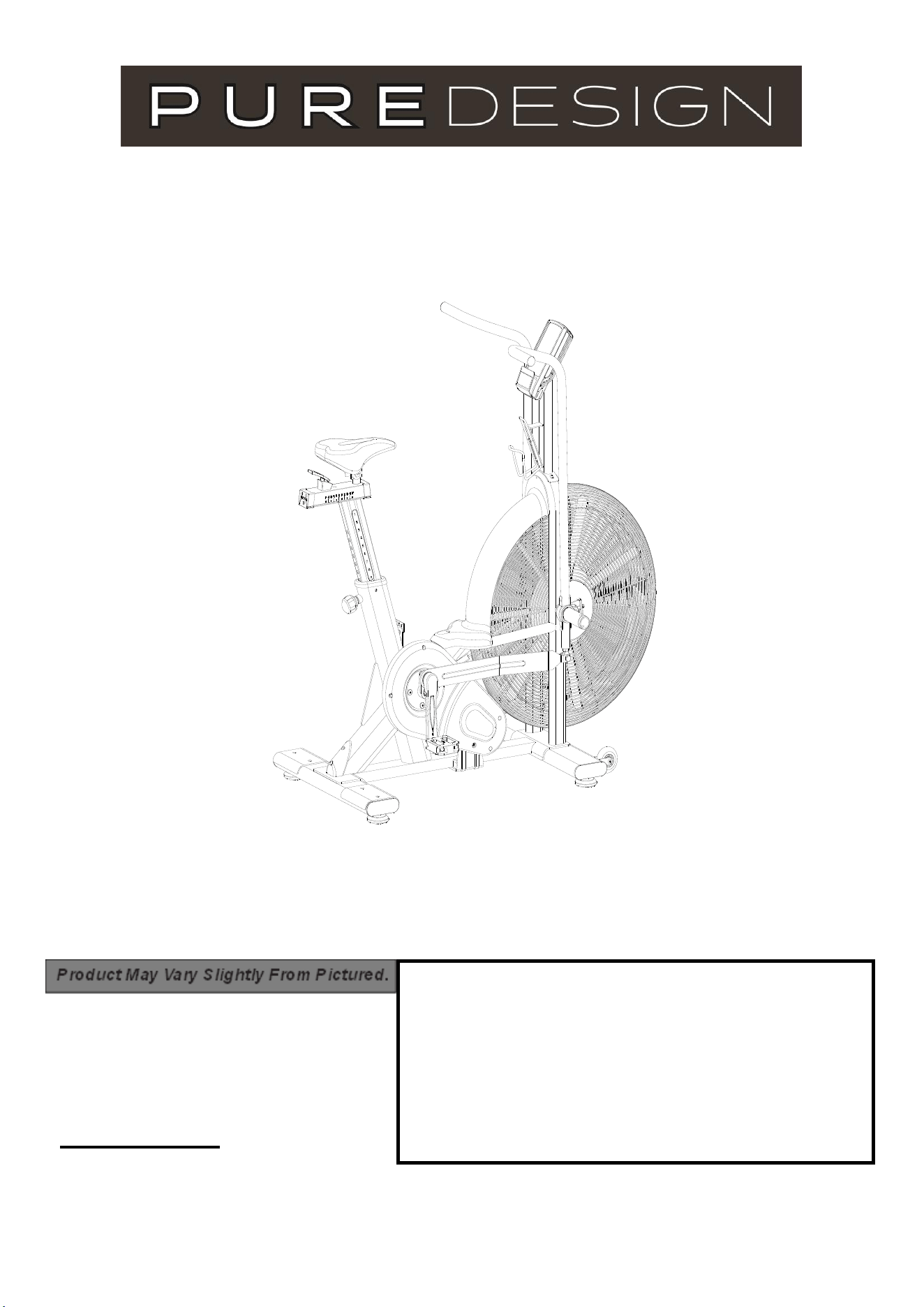
OWNER’S MANUAL
ITEM NO.: AB8
CONTACT INFO
Address: 72 South Street, Rydalmere,
NSW 2112
Phone: 02 9898 1405

2
Contents
Safety Information
Assembly Instructions
Console Instruction
Exploded Diagrams
Parts List
03
04
08
16
17

3
Safety Information
Note the following precaution before assembling or operating the machine.
Keep children and pets away from the Spinning Bike at all times. DO NOT leave unattended
children in the same room with the machine.
Handicapped or disabled persons should not use the Air Bike without the presence of a
qualified health professional or physician.
If the user experiences dizziness, nausea, chest pain, or any other abnormal symptoms,
STOP the workout at once. CONSULT A PHYSICIAN IMMEDIATELY.
Before beginning training, remove all within a radius of 2 meters from the machine. DO NOT
place any sharp objects around the Spinning Bike.
Position the Spinning Bike on a clear, level surface away from water and moisture. Place mat
under the unit to help keep the machine stable and to protect the floor.
Use the Spinning Bike only for its intended use as described in this manual. DO NOT use
any other accessories not recommended by the manufacturer.
Assemble the machine exactly as the descriptions in the instruction manual.
Check all bolts and other connections before using the machine for the first time and ensure
that the trainer is in the safe condition.
Hold a routine inspection of the equipment. Pay special attention to components which are the
most susceptible to wear off, i.e. connecting points and wheels. The defective components
should be replaced immediately. The safety level of this equipment can only be maintained by
doing so. Please don't use the Spinning Bike until it is repaired well.
NEVER operate the Spinning Bike if it is not functioning properly.
This machine can be used for only one person’s training at a time.
Do not use abrasive cleaning articles to clean the machine. Remove drops of sweat from the
machine immediately after finishing training.
Always wear appropriate workout clothing when exercising. Running or aerobic shoes are also
required.
Before exercising, always do stretching first.
The power of the machine increases with increasing the speed, and the reverse. The
machine is equipped with adjustable knob, which can adjust the resistance.
4
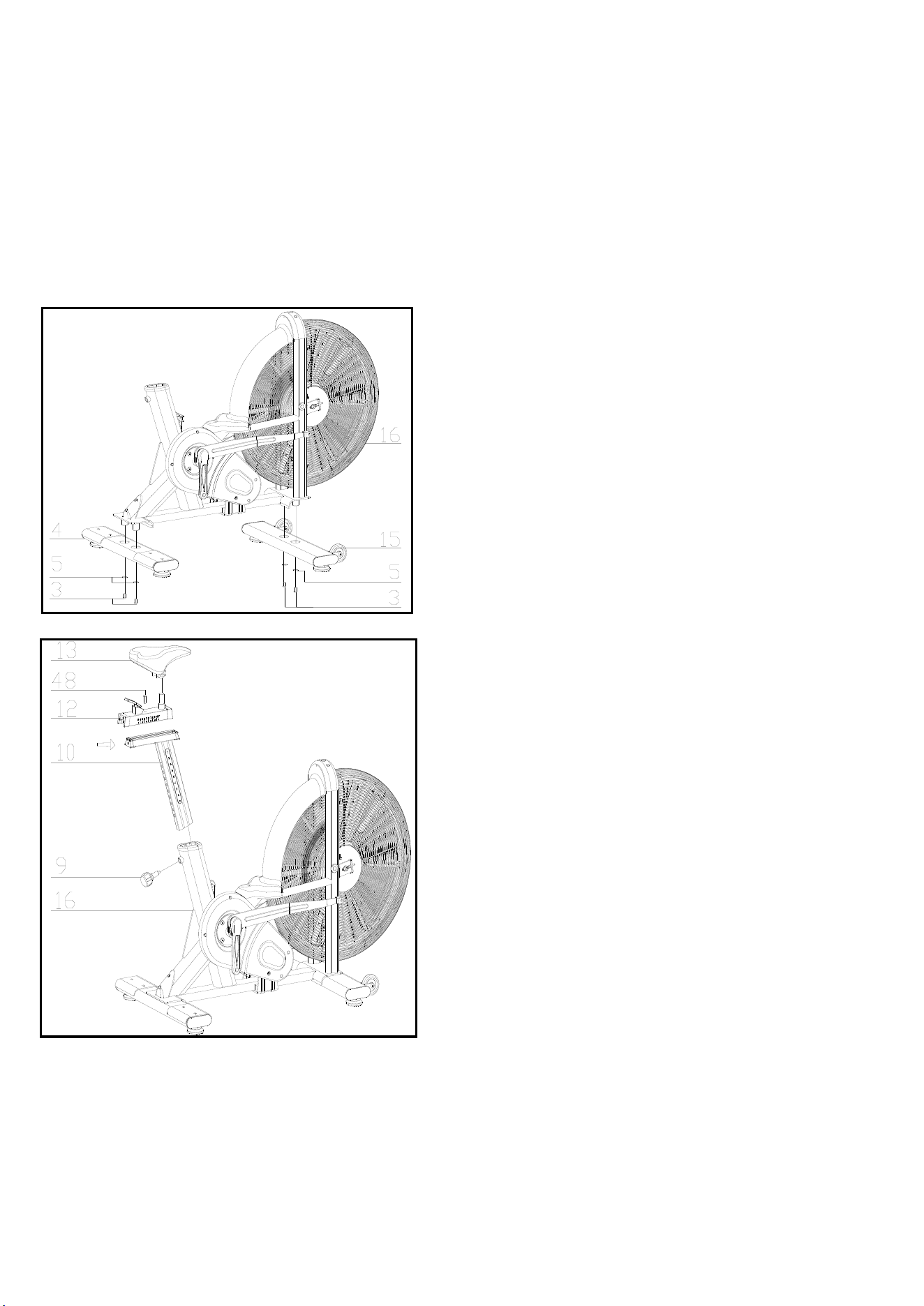
FIG.1
Assembly Instruction
1.PREPARATION:
A. Before assembling make sure that you will have enough space around the item.
B. Use the present tooling for assembling.
C. Before assembling please check whether all needed parts are available (at the above of this instruction sheet
you will find an explosion drawing with all single parts (marked with numbers) which this item consists of.
2.ASSEMBLY INSTRUCTION:
:
FIG.2
FI G.2:
Slide the Vertical Seat Post (pt.10) into
the seat post housing on the main frame
(pt.16). And put the knob up, then release
the round nut(pt.48) , Then slide the
Seat Post (pt.12) into the Vertical Seat
Post (pt.10),Then fixing the bolt8 (pt.48),
You will have to slacken the knurled
section of the Adjustment Knob (pt.9) and
pull the knob back and then select the
desired height. Release the knob and
retighten the knurled portion.
Now fix the Seat (pt.13) to the Seat Post
(pt.12) as shown, and tighten the bolts
around the screws under the seat.
FIG.1:
Attach the Front Stabilizer (pt.15) to the
Main Frame (pt.16) using two sets of
Ø 10 Flat Washers (pt.5) and bolt 1 (3).
Attach the Rear Stabilizer (pt.4) to the
Main Frame (pt.16) using two sets of
Ø 10 Flat Washers (pt.5) and bolt 1 (3)
5
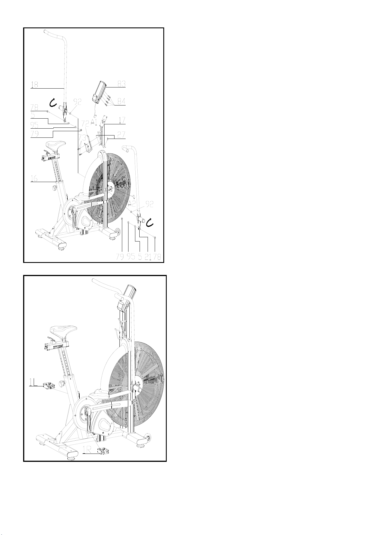
FIG.3
FIG.4
FIG.3:
The left hand assembly (18), the right
wrench assembly (21) and the outer
tooth type gasket (92) are fixed to the
main frame assembly (16) in accordance
with the graphic method,the inner six
angle flat head screws (78), flat washer
(5), Spring washer(95),the lock nut (79)
drive assembly connected then, locking;
electronic connection assembly (17) with
six angle flat head screws (27) fixed to
the main frame assembly (16), the cross
slot screw (73) will Aluminum Alloy kettle
(72) fixed to the main frame assembly
(16) on,
ATTENTION: YOU SHOULD FIX THE
HANDLEBAR TIGHTLY
The electronic meter assembly (83)
with cross slot screw (84) fixed to the
electronic connection assembly (17),
connect the plug (A1&A2),
FIG.4:
The Pedals (pt.1 L & pt.1 R) are
marked "L" and "R" - Left and Right.
Connect them to their appropriate
crank arms. The right crank arm is on
the right- hand side of the cycle as you
sit on it.
Note that the Right pedal should be
threaded on clockwise and the Left
pedal anticlockwise.
6
ADJUSTMENT
To adjust the seat height, slacken the spring knob on the vertical post stem on the main frame
and pull back the knob. Position the vertical seat post for the desired height so that holes are
aligned, then release the knob and retighten it.
To move the seat forward in the direction of the handlebar or backwards away from it, loosen
the adjusting knob and washer and pull the knob back. Slide horizontal seat post into desired
position. Align holes and then retighten the adjusting knob.
To adjus
t the handlebar height, slacken the spring knob and secondary knob and pull both
knobs back. Slide the handlebar post along the housing on the main frame to the desired
height and, with the holes aligned correctly, tighten the spring adjusting knob and then the
secondary knob.
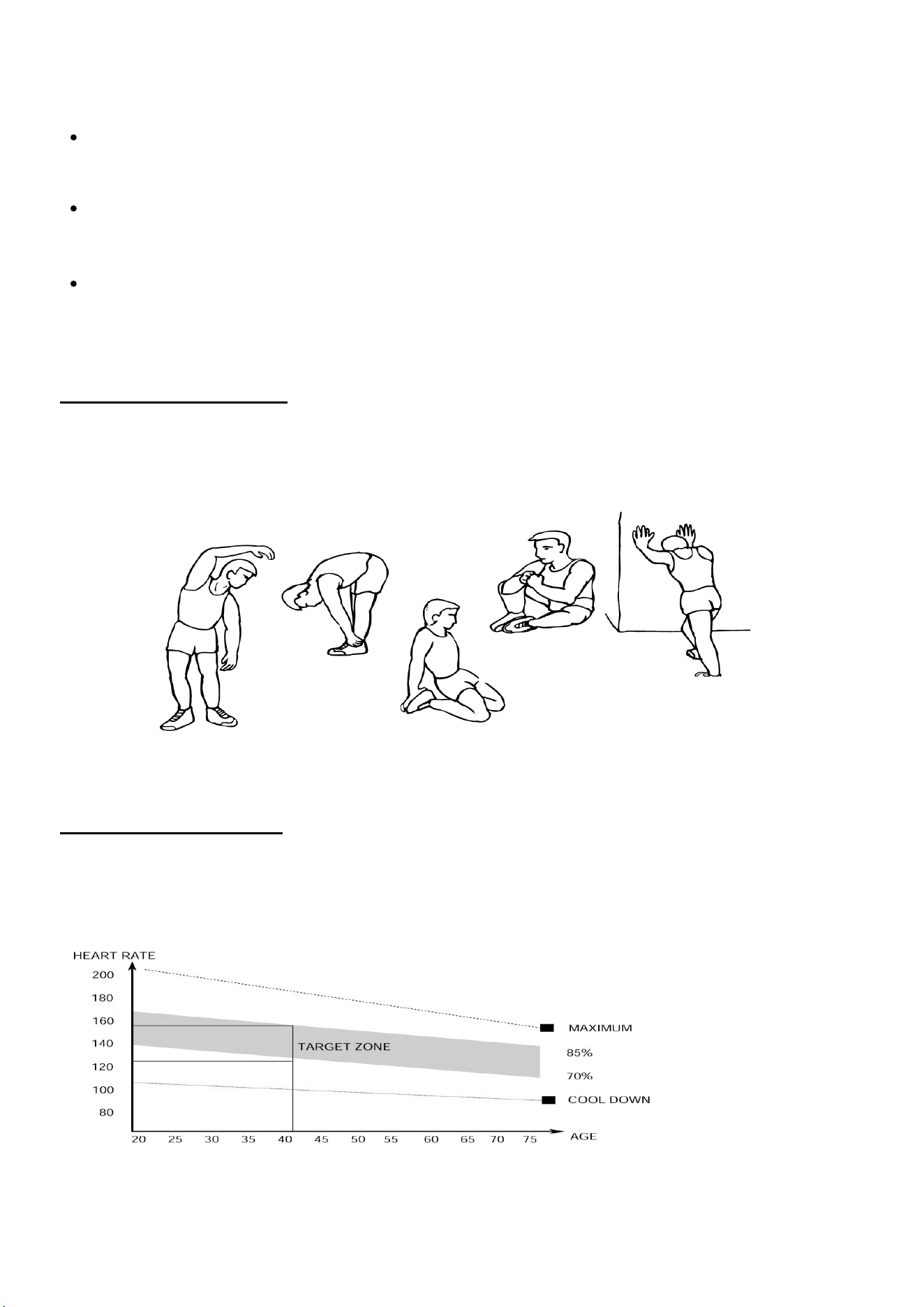
1.The Warm Up Phase
This stage helps get the blood flowing around the body and the muscles working properly. It will
also reduce the risk of cramp and muscle injury. It is advisable to do a few stretching exercises as
shown below. Each stretch should be held for approximately 30 seconds, do not force or jerk your
muscles into a stretch - if it hurts, STOP.
2.The Exercise Phase
This is the stage where you put the effort in. After regular use , the muscles in your legs will
become Stronger. Work to your but it is very important to maintain a steady tempo throughout. The
rate of work should be sufficient to raise your heart beat into the target zone shown on the graph
below.
SIDE BENDS OUTER THIGH
INNER THIGH
FORWARD
BENDS
CALF / ACHILLES
This stage should last for a minimum of 12 minutes for most people
start at about 15-20 minutes
6

7
This stage is to let your Cardio-vascular System and muscles wind down. This is a repeat of the
warm up exercise e.g. reduce your tempo, continue for approximately 5 minutes. The stretching
exercises should now be repeated, again remembering not to force or jerk your muscles into the
stretch.
As you get fitter you may need to train longer and harder. It is advisable to train at least three times
a week, and if possible space your workouts evenly throughout the week.
MUSCLE TONING
To tone muscle while on your Air BIKE you will need to have the resistance set quite high. This
will put more strain on our leg muscles and may mean you cannot train for as long as you would
like. If you are also trying to improve your fitness you need to alter your training program. You
should train as normal during the warm up and cool down phases, but towards the end of the
exercise phase you should increase resistance, making your legs work harder than normal. You
may have to reduce your speed to keep your heart rate in the target zone.
WEIGHT LOSS
The important factor here is the amount of effort you put in. The harder and longer you work the
more calories you will burn. Effectively this is the same as if you were training to improve your
fitness, the difference is the goal.
USE
The tension control knob allows you to alter the resistance of the pedals. A high resistance makes
it more difficult to pedal, a low resistance makes it easier. For the best results set the tension while
the bike is in use.
10/20
INTERVAL
20/10
INTERVAL
CUSTOM
INTERVAL
TARGET
TIME
TARGET
DISTANCE
TARGET
CALORIES
TARGET
HEART
RATE
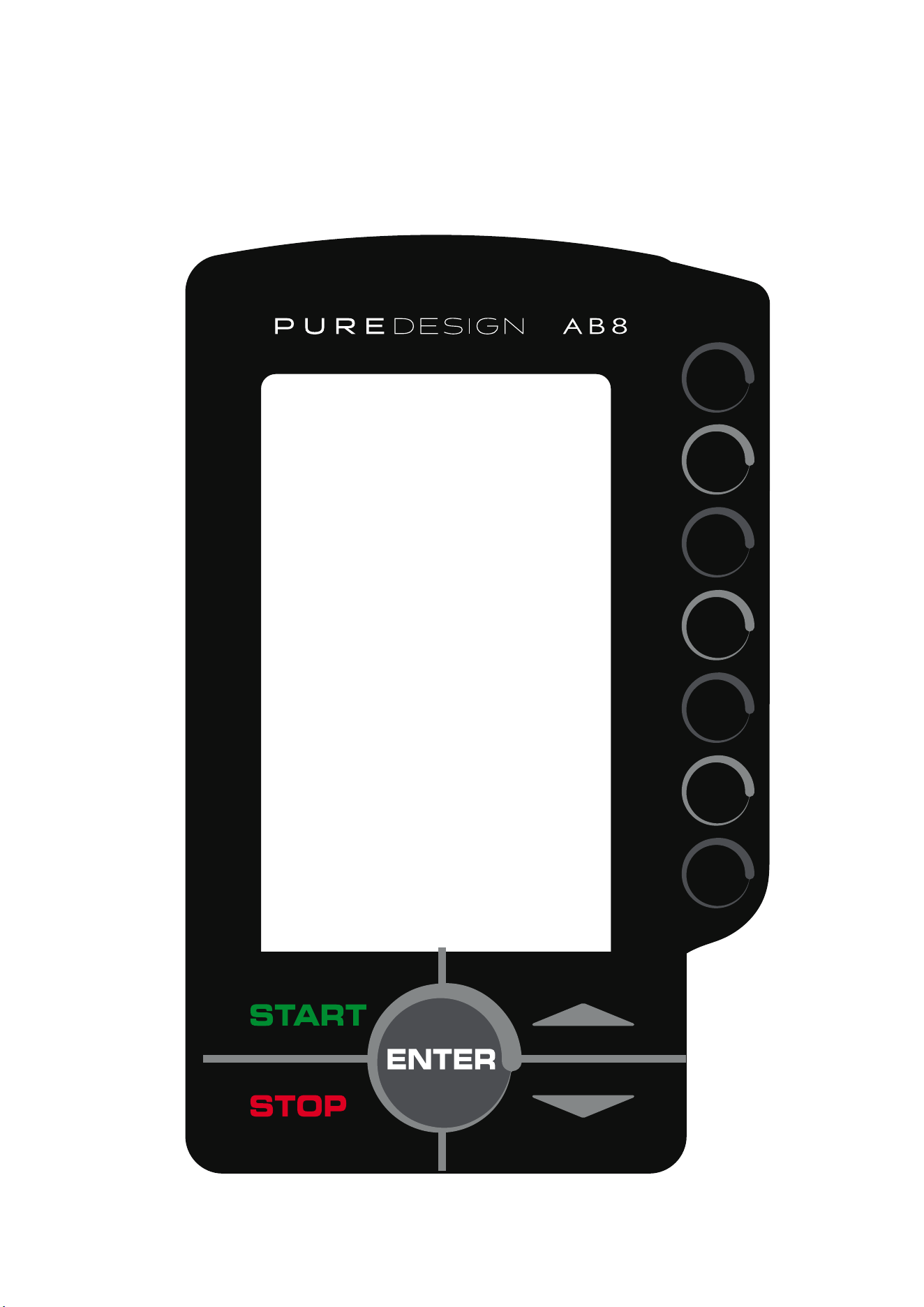
Console Introduction
8
DISPLAY FUNCTIONS
TIME DESCRIPTION
RPM
Display the rotation per minute with range from 0~ 199.
SPEED
Display current training speed. Maximum speed is 99.9 KM/H or ML/H.
TIME
Count up - No preset target. Time will count up from 00:00 to maximum
1:59:59 with each increment is 1 minute.
Count down - The console will countdown from preset time to 00:00:00 and each
preset increment or decrement will be 1 minute between 00:01:00 to 1:59:00.
DISTANCE
Accumulates total distance from 0.0 up to 999.9 KM or ML or count down from
preset value. User may preset target distance value with UP/DOWN key.
Each increment is 1.0KM or ML.
CALORIES
Accumulates calories consumption or count down during training from 0
to maximum 999 calories.User may preset target Calories with UP/DOWN key.
.
WATT
Display the power consumption during training.
Display Range: 0~1999.
PULSE
User may set up target pulse value from 0~30 to 230 and the console buzzer will
beep when the actual heart rate is over the target value during workout.
BUTTON FUNCTION
TIME DESCRIPTION
START
To start workout quickly or resume workout in Stop mode.
STOP
To stop/pause workout.
To clear up all settings.
Hold on this key for 2 seconds to reboot the console.
DOWN
To adjust Distance, Calories, Heart-rate, Time, Age value down.
UP
Target Distance
Target Calories
Target Heart-rate
Target Time
Interval
ENTER
·
Fast access to Target Distance training mode.
There are 3 programs: INTERVAL 10/20, INTERVAL 20/10, Custom.
To confirm settings or enter program.
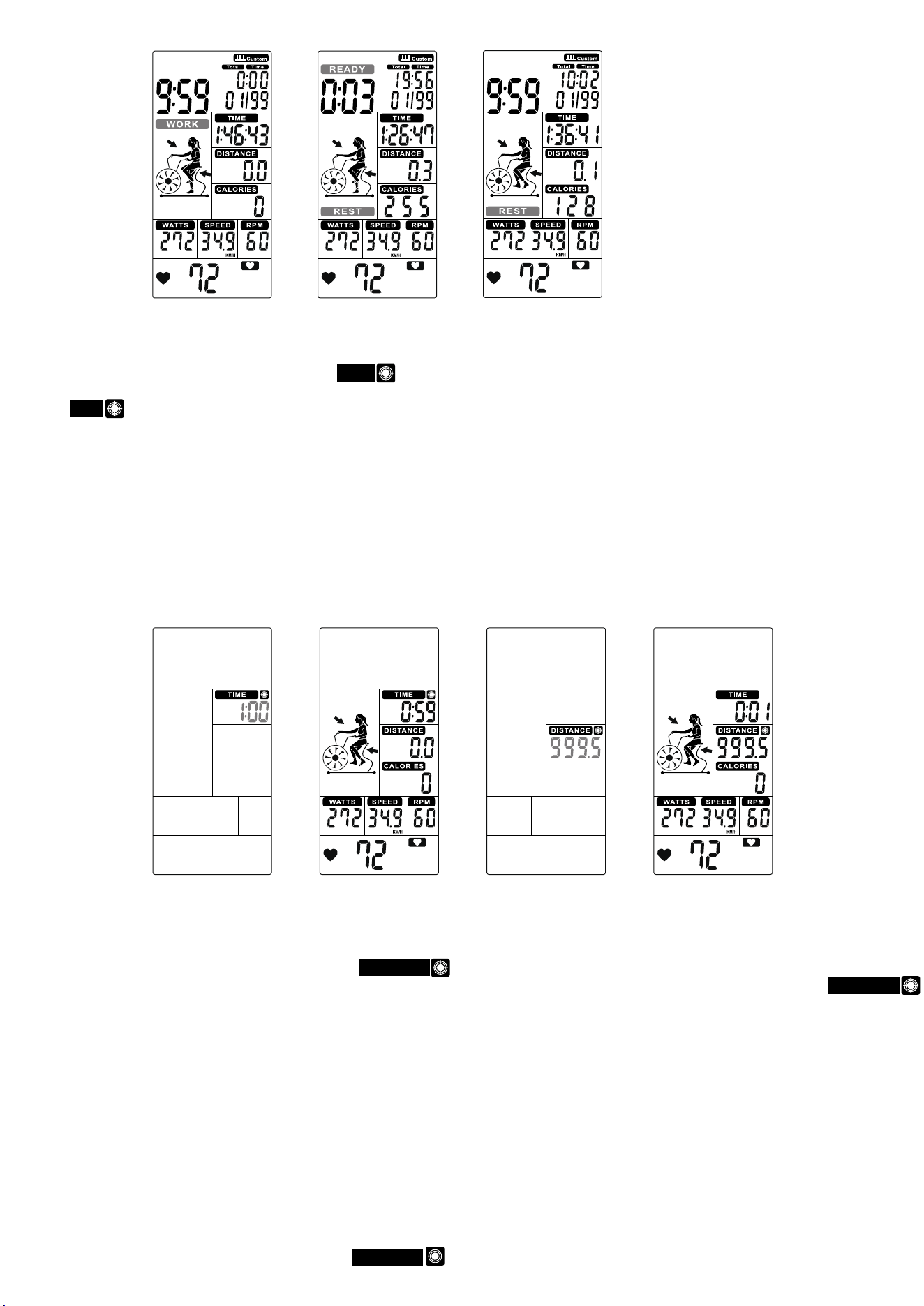
OPERATION INSTRUCTION
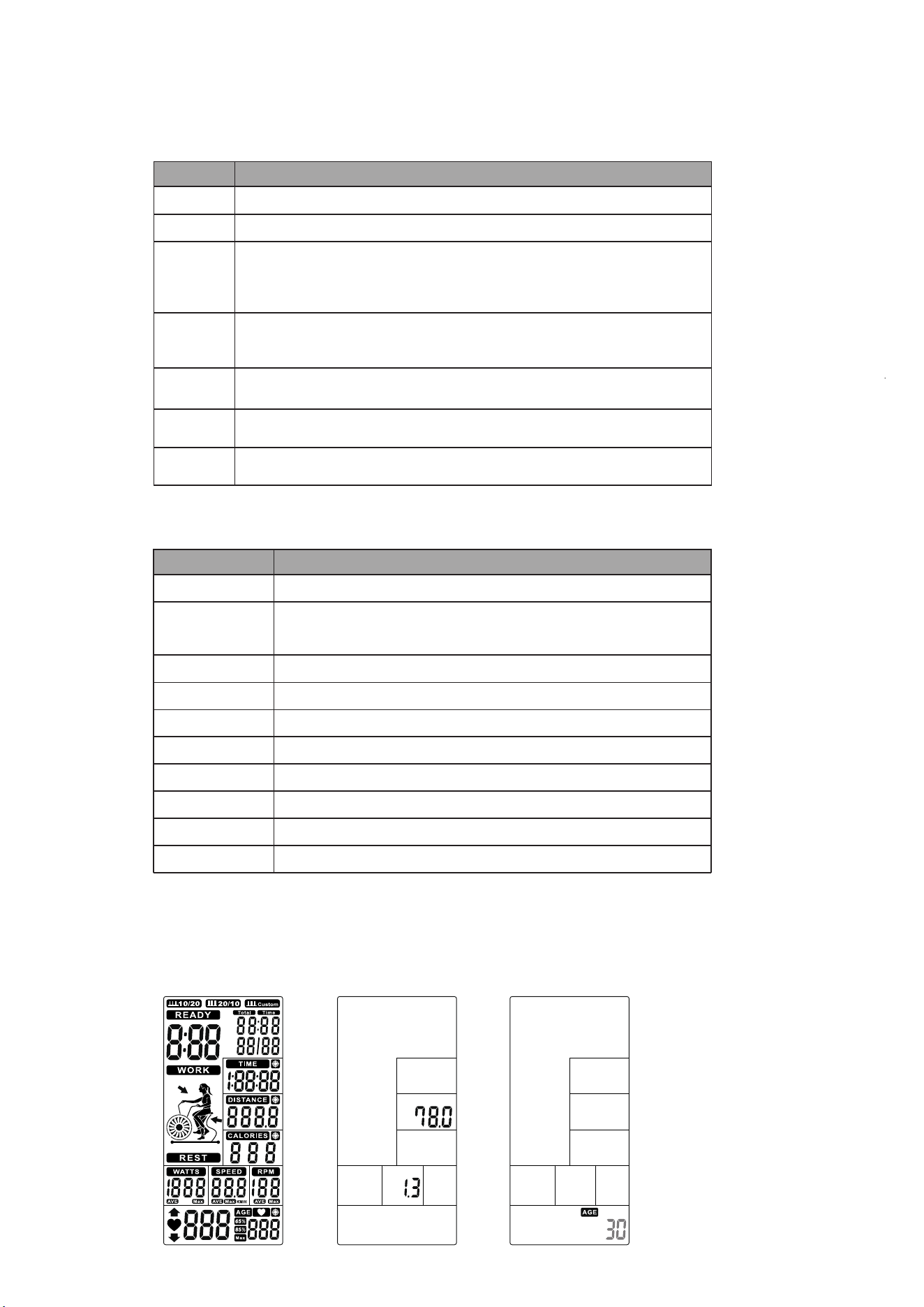
1. When POWER ON, LCD will full display 2s (Figure 1) with long beep sound, then display wheel diameter 1s in
DIST area (Figure 2). Then enter into AGE setting mode , the AGE flashing to be set (Figure 3). Press the
UP/DOWN to set age and press ENTER to confirm then go to Standby mode.
Figure 2
Figure 3
Figure 1
To adjust Distance, Calories, Heart-rate, Time, Age value up.
Fast access to Target Calories training mode.
Fast access to Target Heart Rate training mode.
Fast access to Target Time training mode.
9
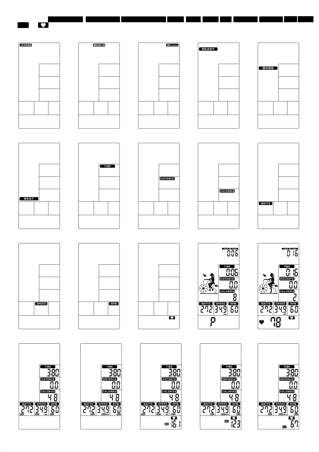
2.
The window of INTERVAL10/20, INTERVAL10/20 INTERVAL CUSTOM, READY, WORK, RESET, TIME, DISTANCE CALORIES WATT SPEED
RPM and will flash by sequence in every 1s (Figure 4~Figure 16).
If no input of key operation or RPM signal or pulse input for 60s, computer will go to Sleeping mode.
Figure 4 Figure 5 Figure 6 Figure 7 Figure 8
Figure 9 Figure 10 Figure 11 Figure 12 Figure 13
Figure 14 Figure 15 Figure 16 Figure 17 Figure 18
Figure 19 Figure 20
Figure 21
Figure 22 Figure 23
10
3. Select Manual, Interval, Target Distance, Target Calories, Target HR, Target Time program:
3.1 Manual mode:
①
In Standby mode, press START to start workout quickly, the buzzer sound 1 second. TOTAL TIME/ TIME/ DISTANCE/ CALORIES/ WATTS/
SPEED/ RPM start to count up (Figure 17).
②
Whenever there is Pulse signal input, will light up and symbol will flash and display pulsevalue (Figure 18). Without pulse input, it
will display “P” (Figure 17).
③
No signal input for 30s, buzzer sounds 1 short beep and enter to Wake-up mode. Press any to wake up the console.
④
Press START key once to pause training, Buzzer will sound for 0.5s in every 30s. All values are displaying on LCD and flashing in every 4s.
If continue to stop training for 5 minutes, buzzer sounds 2s and enter to Wake-up mode. Press START to resume workout.
⑤
Press STOP key, TIME will display total workout time; DISTANCE will display total workout distance; CALORIES will display totalconsumption
during workout; WATT, SPEED and RPM will switch to display AVG. & MAX.PULSE window will switch to display 65%, 85% MAX
(Figure 21~23) each 5s.
⑥
With pulse signal input, PULSE window will display user actual pulse. Pulse window displays nothing if no pulse signal input (Figure 19~20).
⑦
Press any PROGRAM key then perform the program accordingly.
3.2 Interval 20/10 mode:
①
②
Cycle time counts down from 3 to 0 then console start, meanwhile buzzer beeps once per second and READY flashes once per
second, counting displays ‘00/08’(Figure 24).
③
Cycle time counts down from 20 to 0 and WORK flashes once per second . Meantime windows displays rotation animation and count down
from 4 minutes. Then TOTAL TIME, DISTANCE, CALORIES, WATTS, SPEED & RPM start calculating, counting displays ‘01/08’(Figure 25).
④
Cycle time counts down from 10 to 0 and REST flashes once per second along with 10 beeps(Figure 26), meanwhile READY willflash in last
3s (Figure 27).
⑤
The above
③
&
④
continuie cycle counting and add 1 per each cycle,until displays 08/08WORK, then go to End page.
⑥
Press START button once enter into PAUSE mode, Buzzer will sound for 0.5s in every 30s. All values are displaying on LCD and
flashing in every 4s. If continue to stop training for 5 minutes, buzzer sounds 2s and enter to Wake-up mode. Press START to resume workout.
⑦
Press STOP or end up training, buzzer beeps 1s then displays TOTAL TIME, DISTANCE,CALORIES for 30s, and WATT, SPEED
& RPM will switch to display AVG. & MAX. PULSE window will switch to display 65%, 85% MAX (Figure 21~23) each 5s.
⑧
With pulse signal input, PULSE window will display user actual pulse and 65%, 85% MAX (Figure 21~23). Pulse window displays nothing if no
pulse signal input (Figure 19~20).
⑨
Press any PROGRAM key then perform the program accordingly.
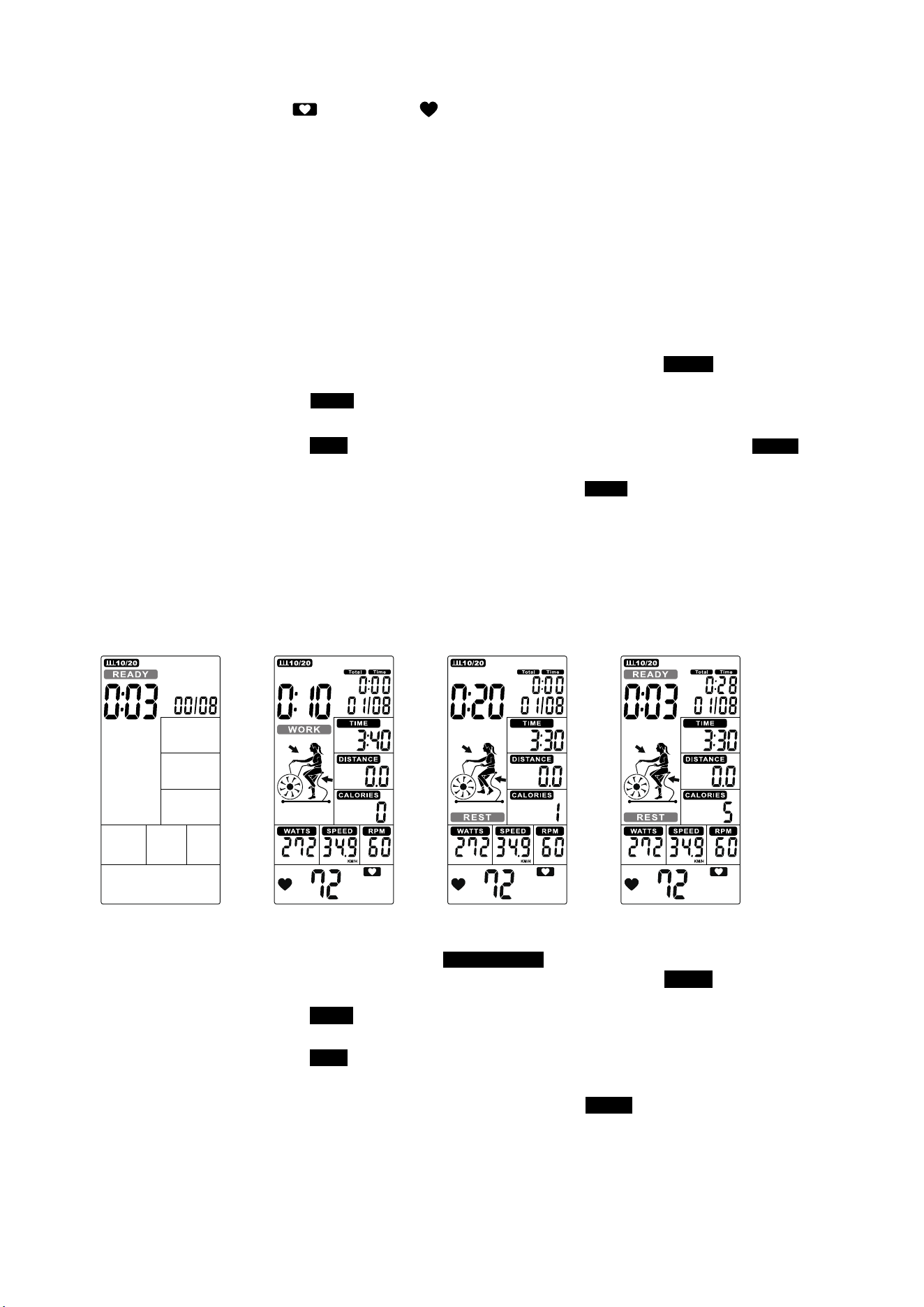
3.3 Interval 10-20 mode:
①
Press INTERVAL to select INTERVAL10/20, press ENTER then INTERVAL10/20 will light up along with buzzer beeps 1s.
②
Cycle time counts down from 3 to 0 then console start, meanwhile buzzer beeps once per second and READY flashes once per
second, counting displays ‘00/08’(Figure 28).
③
Cycle time counts down from 10 to 0 and WORK flashes once per second . Meantime REMAINING will light up and countdownfrom 4 minutes.
ThenTOTAL TIME, DISTANCE, CALORIES, WATTS, SPEED & RPM start calculating, counting displays‘01/08’(Figure 29).
④
Cycle time counts down from 20 to 0 and REST flashes once per second along with beeps (Figure 30), meanwhile READY will flashin last 3s
(Figure 31).
⑤
The above ③&④ continuie cycle counting and add 1 per each cycle, until displays 08/08 WORK , then go to End page.
⑥
Press START button once enter into PAUSE mode, Buzzer will sound for 0.5s in every 30s. All values are displaying on LCD and flashing in
every 4s. If continue to stop training for 5 minutes, buzzer sounds 2s and enter to Wake-up mode. Press START to resume workout.
⑦
Press STOP or end up training, buzzer beeps 1s then displays TOTAL TIME, DISTANCE,CALORIES for 30s, and WATT, SPEED &RPM will
switch to display AVG. & MAX. .PULSE window will switch to display 65%, 85% MAX (Figure 21~23) each 5s.
⑧
With pulse signal input, PULSE window will display user actual pulse. Pulse window displays nothing if no pulse signal input (Figure 19~20).
⑨
Press any PROGRAM key then perform the program accordingly.
Figure 24
11
Press INIERVAL key to select INTERVAL20/10, press ENTER then INTERVAL20/10 will light up, alongwith a long sound for 1s.
Figure 25 Figure 26 Figure 27
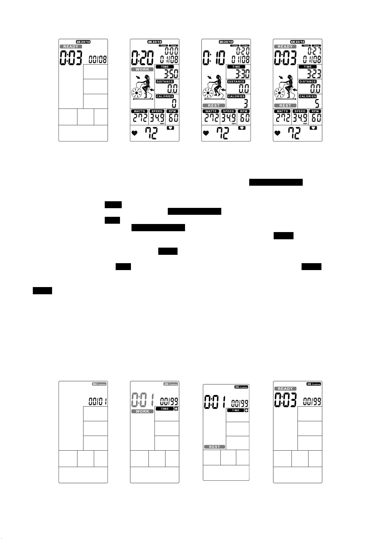
3.4 Interval CUSTOM:
①
Press INTERVAL to select INTERVAL CUSTOM, press ENTER to enter into this mode then INTERVAL CUSTOM 00/XX flashes
to be set along with buzzer beeps 1s. Press UP/DOWN to set 00/XX within 1~99 Circularly. Press ENTER to confirm along with
buzzer beeps 1s then enter into next setting.(Figure 32)
②
TheTIME continues lighting up, WORK and 0:01 will flash, press UP/DOWN to set training time within 0:00~9:59 circularly (Figure 33).
Press ENTER to confirm along with buzzer beeps 1s and INTERVAL CUSTOM continues lighting up.
③
TheTIME continues lighting up, REST will flash, press UP/DOWN to set rest time 0:01~9:59 circularly (Figure 34). Press ENTER
to confirm along with buzzer beeps 1s and INTERVAL CUSTOM continues lighting up.
④
Cycle time counts down from 3 to 0 then console start, meanwhile buzzer beeps once per second and READY flashes once per second,
counting displays ‘00/XX’(Figure 35).
⑤
Cycle time counts down from the preset total time and WORK flashes once per second. Then TOTAL TIME, DISTANCE, CALORIES,
WATTS, SPEED & RPM start calculating, counting displays ‘01/XX’(Figure 36).
⑥
Cycle time counts down from and REST flashes once per second along with buzzer beeps(Figure 37), meanwhile READY will flash
in last 3s(Figure 38).
⑦
The above
③
&
④
continue cycle counting and add 1 per each cycle, until the WORK setting value finished then go to End page.
⑧
In WORK mode, buzzer beeps 1s then enter into wake up mode if no any signal inputs within 30s.
⑨
Press START button once enter tnto PAUSE mode, Buzzer will sound for 0.5s in every 30s. All values are displaying on LCD and flashing in
every 4s. If continue to stop training for 5 minutes, buzzer sounds 2s and enter t Wake-up mode. Press START to resume workout.
⑩
Press START button or end up training, buzzer beeps 1s then displays TOTAL TIME, DISTANCE, CALORIES for 30s, and WATT, SPEED& RPM
will switch to display AVG. & MAX. PULSE window will switch to display 65%, 85% MAX (Figure 21~23) each 5s.
⑪
With pulse signal input, PULSE window will display user actual pulse. Pulse window displays nothing if no pulse signal input (Figure 19~20).
⑫
Press any PROGRAM key then perform the program accordingly.
Figure 28 Figure 29 Figure 30 Figure 31
Figure 32 Figure 33
Figure 34
Figure 35
12
3.5 Target TIME mode:
①
②
TIME value is flashing, press UP and DOWN to adjust value (Figure 39) and press ENTER to confirm meanwhile buzzer beeps 1s and
TIME lasting lighting up.
③
Preset TIME value counts down , DISTANCE, CALORIES, WATTS, SPEEED, RPM start to count up. (Figure 40)
④
Press START button once enter into PAUSE mode,Buzzer will sound for 0.5s per second within 30s. All values are displaying on LCD and
flashing in every 2s. If continue to stop training for 5 minutes, buzzer sounds 2s and enter to Wake-up mode. Press START to resume workout.
⑤
No signal inputs for 30s, buzzer sounds 1 short beep and enter to Wake-up mode.
⑥
Press STARTor end up training, TIME will display total workout time; DISTANCE will display total workout distance; CALORIES will display total
consumption during workout; WATT, SPEED and RPM will switch to display AVG. & MAX. PULSE window will switch to display 65%, 85% MAX
(Figure 21~23) each is.
⑦
With pulse signal input, PULSE window will display user actual pulse. Pulse window displays nothing if no pulse signal input (Figure 19~20).
⑧
Press any PROGRAM key then perform the program accordingly.
3.6 Target Distance mode:
①
In Standby mode, press Target Distance key and DISTANCE will light up, along with a long sound for 1s.
②
DISANCE value is flashing, press UP and DOWN to adjust (Figure 41). Press ENTER to confirm meanwhile buzzer beeps 1s and DISTANCE
lasting lighting up.
③
Preset DISTANCE value counts down, TIME, CALORIES, WATTS, SPEEED, RPM start to count up. (Figure 42)
④
Press START button once enter into PAUSE mode,Buzzer will sound for 0.5s per second within 30s. All values are displaying on LCD and
flashing in every 2s. If continue to stop training for 5 minutes, buzzer sounds 2s and enter to Wake-up mode.
Press START to resume back workout.
⑤
No signal input for 30s, buzzer sounds 1s and enter to Wake-up mode.
⑥
Press STOP key or end up training, TIME will display total workout time; DISTANCE will display total workout distance; CALORIES will display
total consumption during workout; WATT, SPEED and RPM will switch to display AVG. & MAX. PULSE window will switch to display 65%,
85% MAX (Figure 21~23) each 5s.
⑦
With pulse signal input, PULSE window will display user actual pulse. Pulse window displays nothing if no pulse signal input (Figure 19~20).
⑧
Press any PROGRAM key then perform the program accordingly.
3.7
Target Calories mode:
①
In Standby mode, press Target Calories key and CALORIES will light up, along with a long sound for 1s.
Figure 36 Figure 37
Figure 38
Figure 39
Figure 40
Figure 41
Figure 42
13
In Standby mode, press Target Time key and TIME will light up, along with a long sound for 1s.
②
CALORIES value is flashing, press UP and DOWN to adjust (Figure 43). Press ENTER to confrim meanwhile buzzer beeps 1s and CALORIES
lasting lighting up
③
Preset CALORIES value counts down ,TIME, DISTANCE, WATTS, SPEEED & RPM start to count up.(Figure 44).
④
Press START button once enter into PAUSE mode, Buzzer will sound for 0.5s per second within 30s. All values are displaying on LCD and
flashing in every 2s. If continue to stop training for 5 minutes, buzzer sounds 2s and enter Wake-up mode. Press STARTto resume workout.
⑤
No signal input for 30s, buzzer sounds 1s and enter to Wake-up mode.
⑥
Press STOP key or end up training, TIME will display total workout time; DISTANCE will display total workout distance; CALORIES will display
total consumption during workout; WATT, SPEED and RPM will switch to display AVG. & MAX. PULSEwindow will switch to display 65%,
85% MAX (Figure 21~23) in each.
⑦
With pulse signal input, PULSE window will display user actual pulse. Pulse window displays nothing if no pulse signal input (Figure 19~20).
⑧
Press any PROGRAM key then perform the program accordingly.
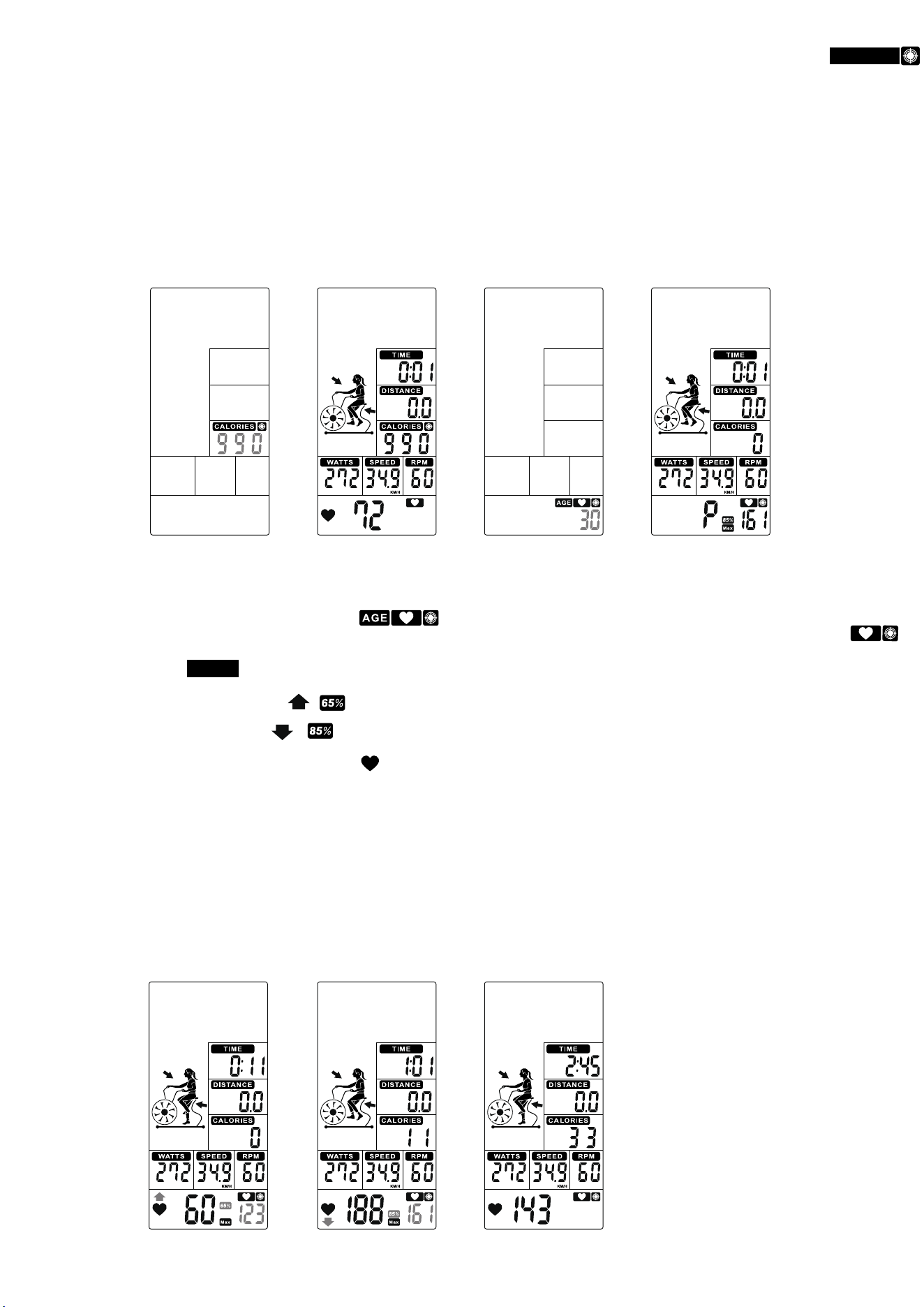
3.8
Target HR mode:
①
In Standby mode, press Target Heart-Rate key and will light up, along with along sound for 1s.
②
AGE value is flashing, press UP and DOWN to preset your Age (Figure 45). Press ENTER to confirm along with buzzer beeps 1S and
HEART RATE last lighting up.
③
When start workout, MAX HRlights up, 65% & 85% Heart rate will switch to display. TIME/ DISTANCE/ CALORIES/ WATTS/SPEED/ RPM
will calculate workout value (Figure 46).
④
When Heart Rate goes below to 65%, & & value will flash. And buzzer sounds in every 10s until user HR achieve above 65% (Figure 47).
⑤
When Heart Rate exceeds to 85%, & & value will flash. And buzzer sounds in every 10s until user HR goes below 85% (Figure 48).
⑥
When Heart Rate goes between 65% ~ 85%, only will flash (Figure 49).
⑦
No signal input for 30s, buzzer sounds 1 short beep and enter to Wake-up mode.
⑧
Press START button once enter into PAUSE mode,Buzzer will sound for 0.5s per second within 30s. All values are displaying on LCD and
flashing in every 2s. If continue to stop training for 5 minutes, buzzer sounds 2s and enter to Wake-up mode. Press STARTto resume workout.
⑨
Press STOP again or end up training in 15s, TIME will display total workout time; DISTANCE will display total workout distance; CALORIES will
display total consumption during workout; WATT, SPEED and RPM will switch to display AVG. & MAX. PULSEwindow will switch to display 65%,
85% MAX (Figure 21~23) each 5s.
⑩
With pulse signal input, PULSE window will display user actual pulse. Pulse window displays nothing if no pulse signal input (Figure 19~20).
* Press any PROGRAM key then perform the program accordingly.
Figure 43
Figure 44
Figure 45
Figure 46
Figure 47 Figure 48 Figure 49
14
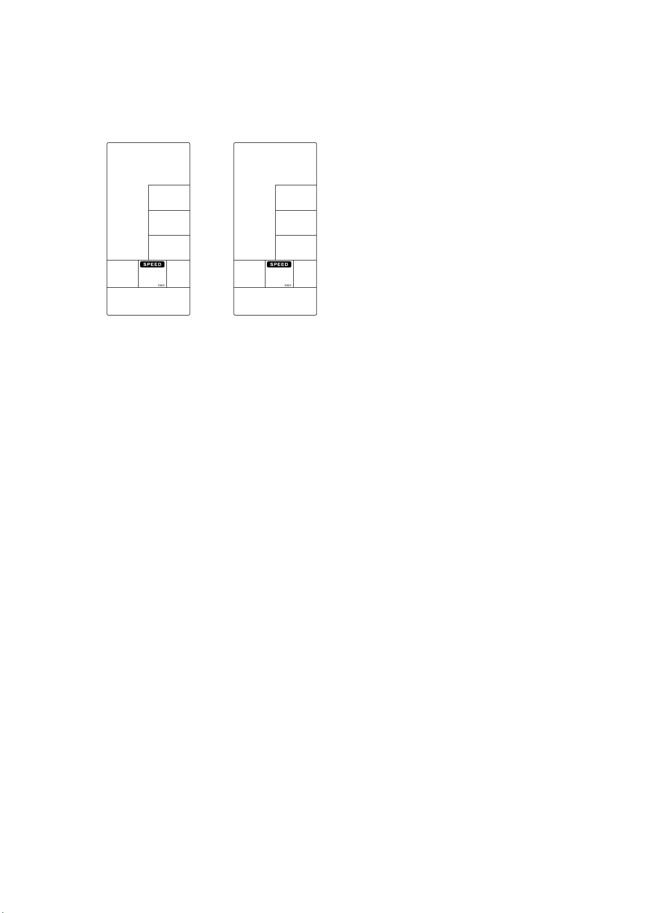
OPTION SETTING:
SETTING mode-
1. Hold on START&ENTER key for 2s, buzzer will sound 1 long beep. SPEED keep lighting up, M/H,KM/H flash once per second (Figure 50~51).
2. Press UP or DOWN to select KM/H or M/H, press ENTER to confirm tnen skip to Standby mode.
3. No action to console for 30s, it will go to Standby mode.
RESET mode-
1. In any mode, press STOP for 2s, system will do TOTAL RESET.
2. LCD falsh in every 2 seconds, buzzer sound for 2 seconds.
3. Reverse to Standby page, all setting resume to preset value.
SLEEPING mode-
In Standby mode, if no key press/RPM/pulse input for 30s, console will go to SLEEPING mode.
Figure 50 Figure 51
15
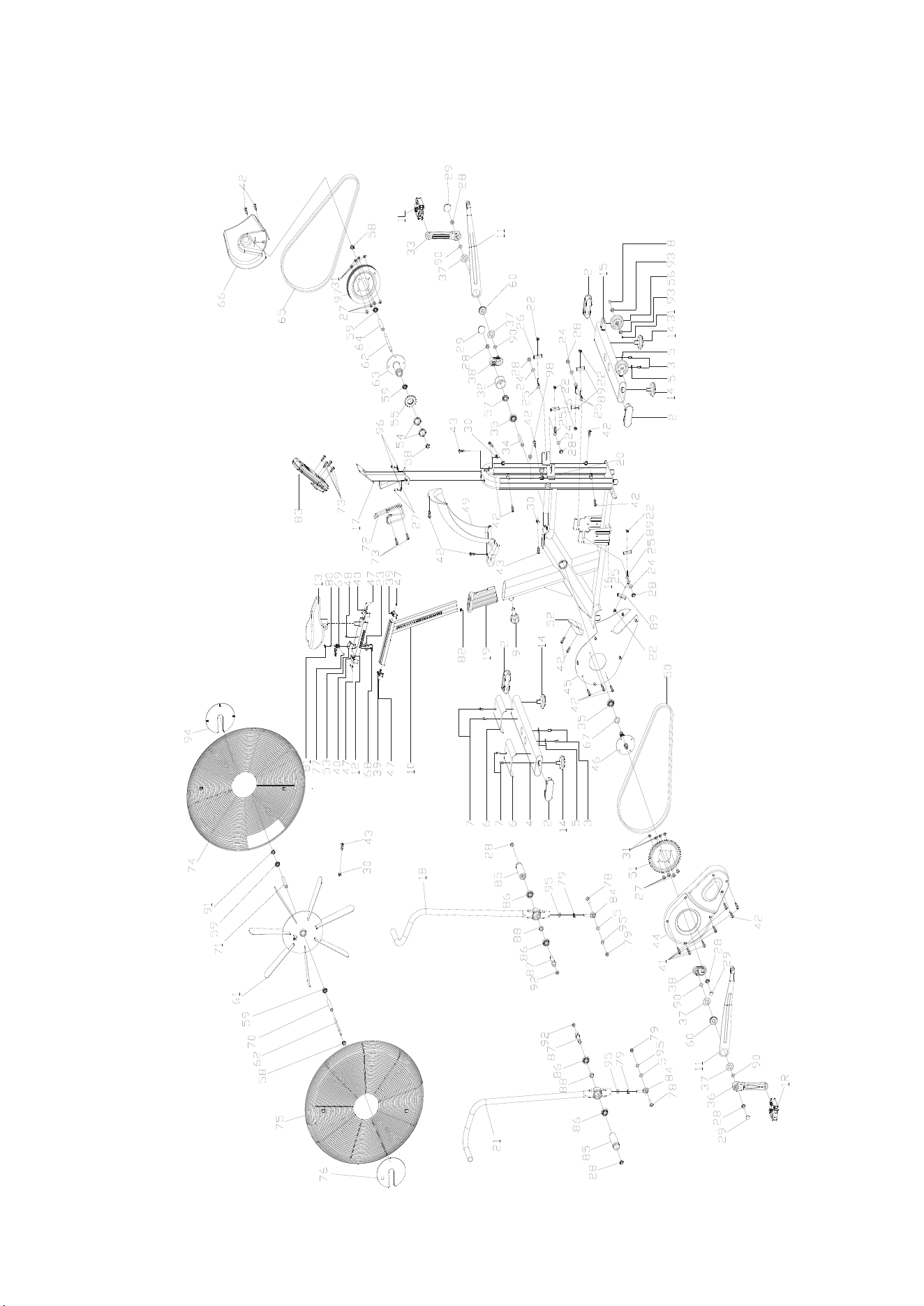
16
Exploded Diagram

NO. DESCRIPTION OF PARTS QTY
1 Pedal 1
2 End cap3 4
3 Bolt 1 4
4 Rear stabilizer 1
5 Flat washer 6
6 Front cover 2
7 Bolt 1 4
8 Bolt 2 2
9 Shape knob 1
10 Vertical seat post 1
11 Drive assembly 2
12 Seat post 1
13 Seat 1
14 Stopper 4
15 Front stabilizer 1
16 Main frame 1
17 Electronic watch connecting assembly 1
18 The left handlebar assembly 1
19 Plastic sleeve 1
20 Sensor 1
21 Right handlebar assembly 1
22 Nut 6
23 Fixing nut 2 1
24 Flat washer 4
25 Fixing bolt 2
26 Pull out the fixed piece 2
27 Bolt 1 10
28 Nut 10
29 Crank end cap 4
30 Sprocket buckle 9
31 Nut 10
32 Plastic ring 1
33 Left crank 1
34 Long fixing tube 1
35 Bearing 2
36 Right crank 1
37 Outer spring 4
38 Crank drive assembly 2
17
Part List

39 Cover 2
40 Cover 2
41 Screw 1 6
42 Screw 2 18
43 Screw 3 6
44 Chain cover 1 1
45 Chain cover 2 1
46 Axis 1
47 Bolt 7 6
48 Bolt 8 1
49 Sweat proof cover 1
50 Short chain wheel 1
51 Belt wheel 1
52 Front cover 1
53 Handle base 1
54 Lock nut 2
55 Chain wheel 1 1
56 Wheel 2
57 Fixing nut 1
58 Fixing nut 2 3
59 Bearing 4
60 Bearing 2
61 Rim assembly 1
62 Flywheel shaft 2
63 Double drive assembly 1
64 Double drive inner sleeve 1
65 Belt 1
66 Chain cover 3 1
67 Short fixing tube 1
68 Bolt 1 2
69 Handle 1
70 Flywheel outer tube 1
71 Flywheel inner casing 1
72 B0ttle holder 1
73 Screw 3 6
74 The left wheel cover 1
75 Right wheel cover 1
76 Fan baffle 1
77 Handle rotary copper sleeve 1
18

78 Bolt 3 2
79 Nut 2
80 Bolt 16 1
81 Handle cover 1
82 Nut 2
83 Computer 1
84 Universal joint 2
85 Foot lever 2
86 Bearing 4
87 Foot lever 2
88 Foot lever bushing 2
89 Small retaining plate 4
90 Corrugated gasket 4
91 Fixing nut 1 1
92 Nut 2
93 Bearing 4
94 Fan baffle 1
95 Spring washer 2
96 Spring washer 2 10
97 Belt wheel 1
98 Plastic plug 1
99 Fixing bolt 4
19