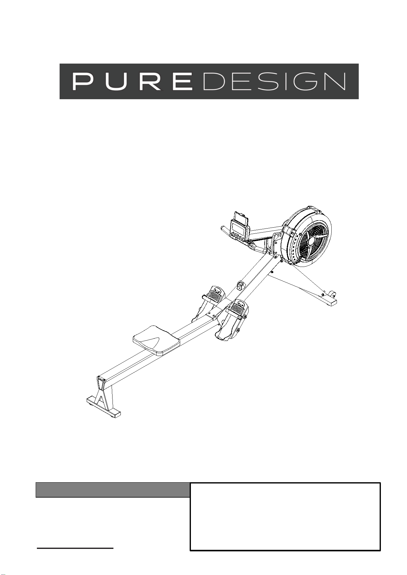
OWNER’S MANUAL
ITEM NO.: PR10
Product May Vary Slightly From Pictured.
CONTACT INFO
Address: 72 South Street, Rydalmere,
NSW 2112
Phone: 02 9808 1405

2
TABLE OF CONTENTS
Safety Instructions
....................................... 2
Before You Begin
......................................... 3
Hardware Identification Chart
.................... 4
Assembly Instructions
............................... 5
Computer Instructions
............................... 11
Operational Instructions
.......................... 17
Maintenance
............................................... 18
Storage ........................................................ 21
Product Parts Drawing ............................... 22
Parts List...................................................... 23
SAFETY INSTRUCTIONS
1.
To reduce the risk of serious injury, read the following Safety Instructions before using the
ROWER.
2.
Save these instructions and ensure that other exercisers read this manual prior to using the
ROWER
for the first time.
3.
Read all warnings and cautions posted on the
ROWER.
4.
The
ROWER
should only be used after a thorough review of the Owner’s Manual. Make
sure
that it is properly assembled and tightened before use.
5.
We recommend that two people be available for assembly of this product.
6.
Keep children away from the
ROWER.
Do not allow children to use or play on the
ROWER.
Keep children and pets away from the
ROWER
when it is in use.
7.
It is recommended that you place this exercise equipment on an equipment mat.
8.
Set up and operate the
ROWER
on a solid level surface. Do not position the
ROWER
on loose rugs
or uneven surfaces.
9.
Make sure that adequate space is available for access to and around the
ROWER.
10.
Before using, inspect the
ROWER
for worn or loose components, and securely tighten or
replace any worn or loose components prior to use.
11.
Before using, check the condition of the CHAIN(36). Replace the CHAIN(36) if it is cracked or broken.
12.
Consult a physician prior to commencing an exercise program and follow his/her
recommendations in developing your fitness program. If at any time during exercise you feel faint,
dizzy, or experience pain, stop and consult your physician. Failure to follow all warnings and
instructions could result in serious injury or death.
13.
Always choose the workout which best fits your physical strength and flexibility level. Know your
limits and train
within them. Always use common sense when exercising.
14.
Do not wear loose or dangling clothing while using the
ROWER.
15.
Never exercise in bare feet or socks; always wear proper footwear such as running, walking, or
cross training
shoes that fit well, provide foot support, and feature non-skid rubber soles.
16.
Be careful to maintain your balance while using, mounting, dismounting, or assembling the
ROWER,
loss of balance may result in a fall and bodily injury.
17.
Do not use the SEAT(51) to move the
ROWER.
The SEAT(51) will move and the SEAT
CARRIAGE(10) may pinch your hand or fingers. When assembling or separating the unit, keep
all children away and make sure your hands are clear of any pinch point.
18.
The
ROWER
should not be used by persons weighing over 297 lbs /135 kgs.
19.
The
ROWER
should be used by only one person at a time.
3
BEFORE YOU BEGIN
Thank you for choosing the ROWER. We take
great pride in producing this quality product and
hope it will provide many hours of quality exercise
to make you feel better, look better, and enjoy
life to its fullest.
It's a proven fact that a regular exercise program
can improve your physical and mental health.
Too often, our busy lifestyles limit our time and
opportunity to exercise. The ROWER provides a
convenient and simple method to begin your
journey of getting your body in shape and achieving
a happier and healthier lifestyle.
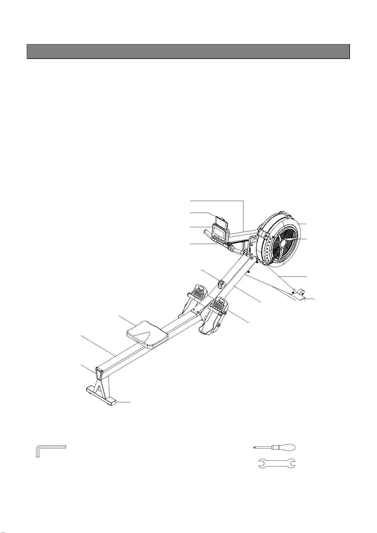
Before reading further, please review the
drawing below and familiarize yourself with the
parts that are labeled.
Read this manual carefully before using the
ROWER.
THE FOLLOWING TOOLS ARE INCLUDED FOR ASSEMBLY :
Allen Wrench (6mm) Screwdriver
Allen Wrench (8mm)
Wrench
Console Monitor Post
Cell Phone Bracket
Console Monitor
Handlebar
Pedal Strap
Seat
Rail Frame
Rail End Cap
Rear Stabilizer
Front
Stabilizer
Main Frame
Right Fan Shroud
Damper
Front Support Leg
Handlebar Holder
4
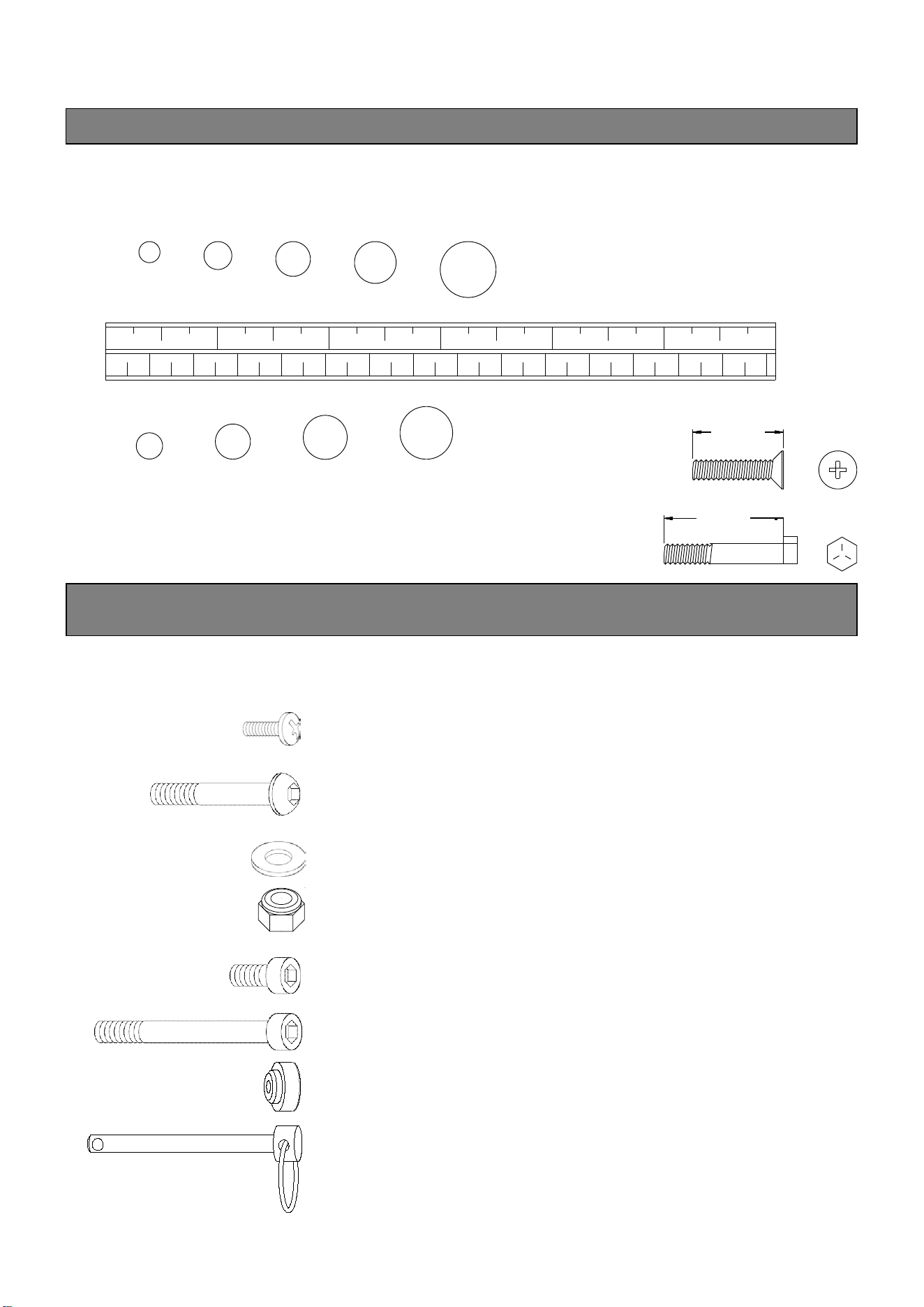
HARDWARE IDENTIFICATION CHART
This chart is provided to help identify the fasteners used in the assembly process. Place the washers or
the ends of the bolts or screws on the circles to check for the correct diameter. Use the small scale to
check the length of the bolts and screws.
3/16" 1/4" 5/16" 3/8" 1/2"
INCHES
0 1/2 1 1/2 2 1/2 3 1/2 4 1/2 5 1/2 6
in.
0 10 20 30 40 50 60 70 80 90 100 110 120 130 140 150
mm.
MILLIMETERS
length
6 8 10 12
NOTICE: The length of all bolts and screws, except those with flat
heads, is measured from below the head to the end of the bolt
or screw. Flat head bolts and screws are measured from the
top of the head to the end of the bolt or screw.
length
After unpacking the unit, open the hardware bag and make sure that you have all the following
fasteners. Some fasteners may be already attached to the parts.
Part Number and Description Qty
72 Philips Head Screw, M6x10mm 2
78 Button Head Cap Screw, M8x75mm 1
79 Flat Washer, M8 9
80 Nylon Lock Nut, M8 1
81 Socket Head Cap Screw, M8x12mm 8
84 Socket Head Cap Screw, M8x160mm 4
9 Foot Pedal End Cap 4
98 Pull Pin 1
ASSEMBLY INSTRUCTIONS
5
ASSEMBLY INSTRUCTIONS
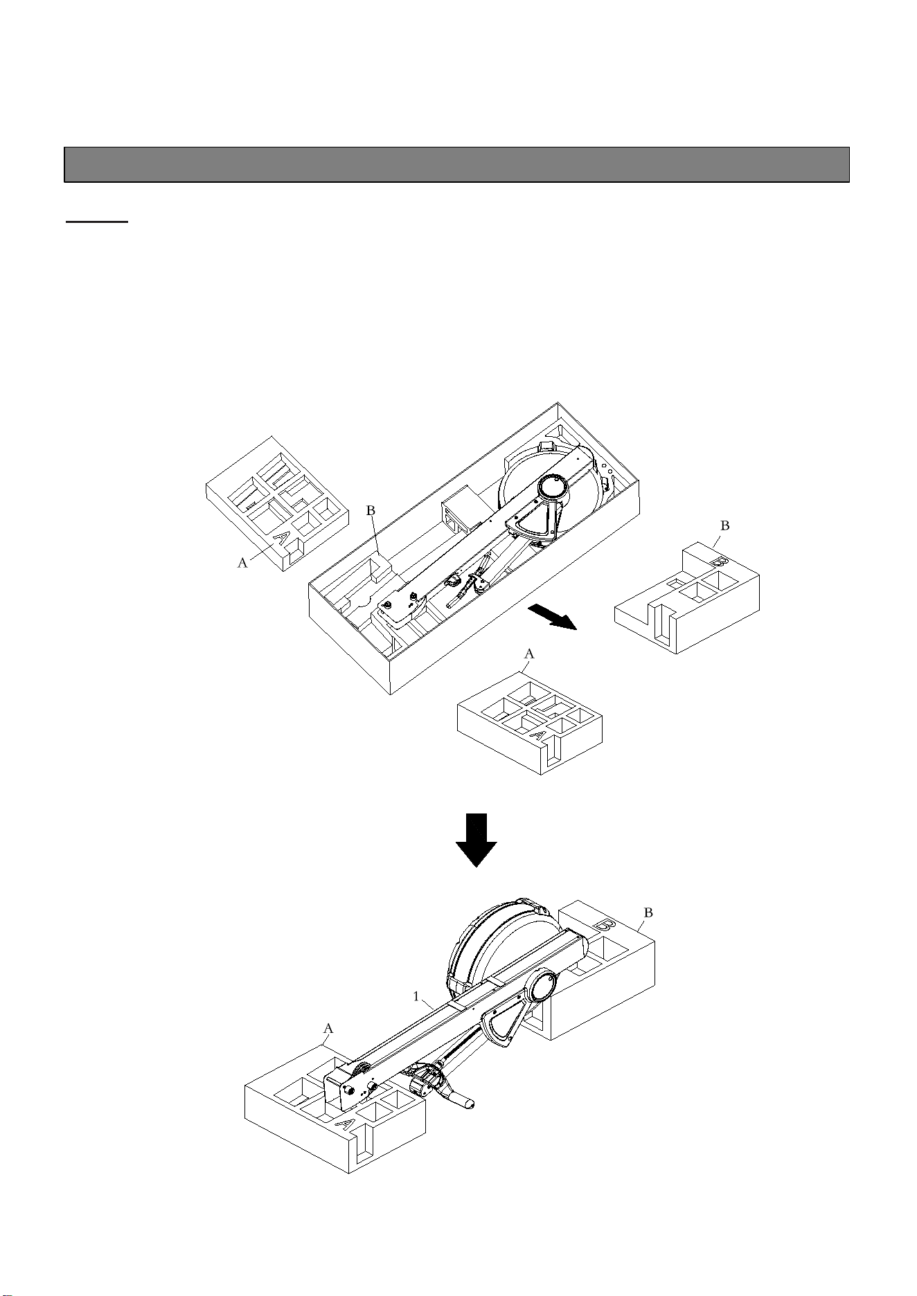
STEP 1
First, take out the packing materials Styrofoam (A) and Styrofoam (B). Then flip them over so
the sides with carved letter are facing up. Take the Main Frame (1) out from the carton and put it
on both Styrofoam (A & B) as picture shown. The Right and Left Fan Shrouds (43 & 44)
should be placed in the groove of Styrofoam (B).
NOTE: Fan Shrouds will be easily damaged if the whole product is placed on the ground directly
during the assembly.
ASSEMBLY INSTRUCTIONS
6
ASSEMBLY INSTRUCTIONS
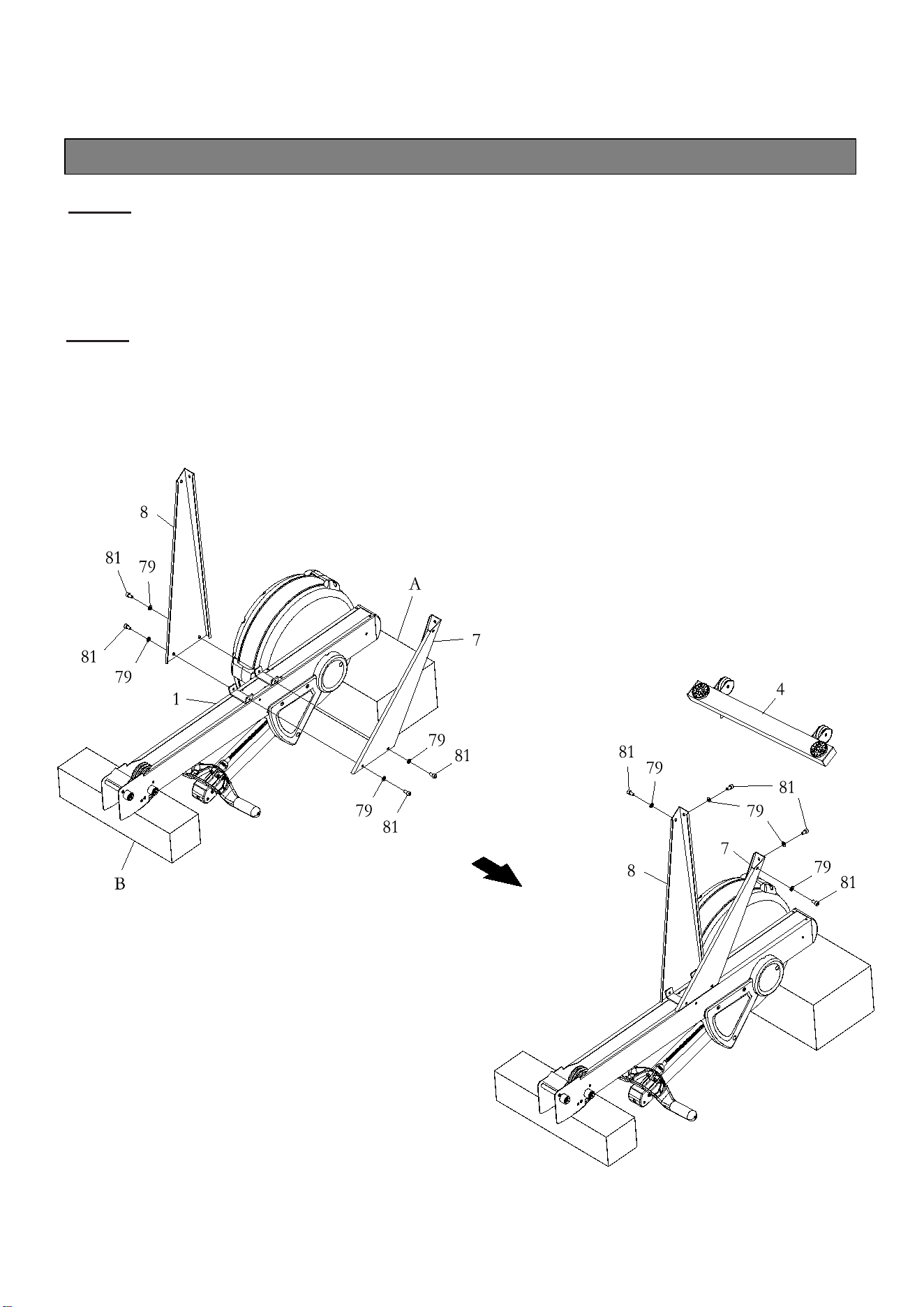
STEP 2
Turn the main assembly of the ROWER upside down and place it in the packing material
Styrofoam (A & B) to avoid damage of housing.
Attach Left and Right Support Legs (7 & 8) to the Main Frame (1) using: 4 PCs of M8x12mm
Socket Head Cap Screw (81) and M8 Flat Washer (79).
STEP 3
Attach the Front Stabilizer (4) to Left and Right Support Legs (7& 8) using: 4 PCs of
M8x12mm Socket Head Cap Screw (81) and M8 Flat Washer (79).
NOTE: Fully tighten all bolts.
ASSEMBLY INSTRUCTIONS
7
ASSEMBLY INSTRUCTIONS
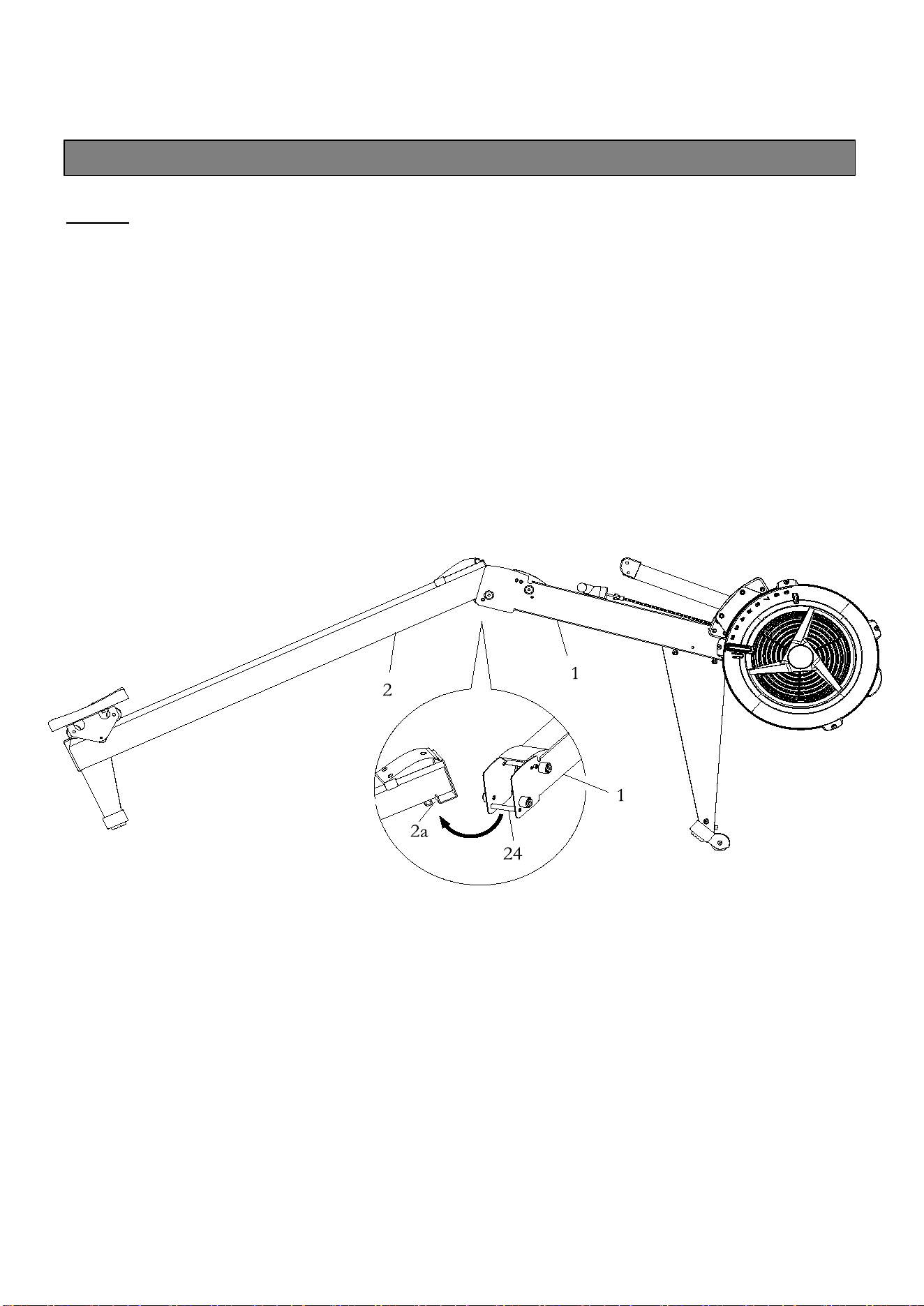
STEP 4
Lift up the Main Frame(1) and Rail Frame(2), then insert Rail Frame(2) into the Main
Frame(1). Fit the Shaft(24) on the Main Frame(1) into the gap of the Rail Frame(2).
NOTE: Fully tighten all bolts.
ASSEMBLY INSTRUCTIONS
8
ASSEMBLY INSTRUCTIONS
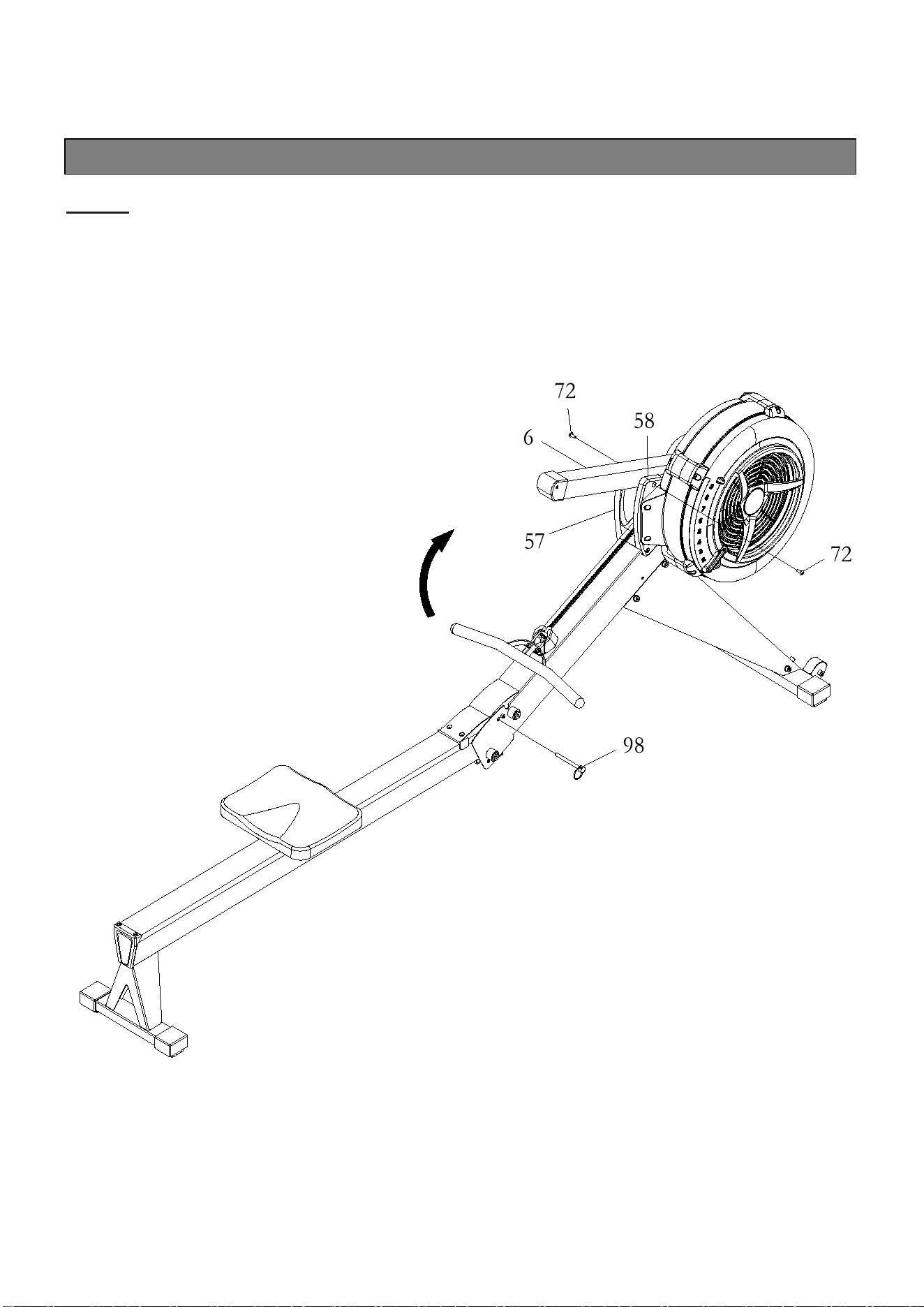
STEP 5
Insert the Pull Pin(98) into the Main Frame(1) and Rail Frame(2).
Attach Console Monitor Post(6) to the Side Covers (57)(58): 2 PCs of M6X10 Phillips Head
Screw(72).
NOTE: Fully tighten all bolts.
ASSEMBLY INSTRUCTIONS
9
ASSEMBLY INSTRUCTIONS
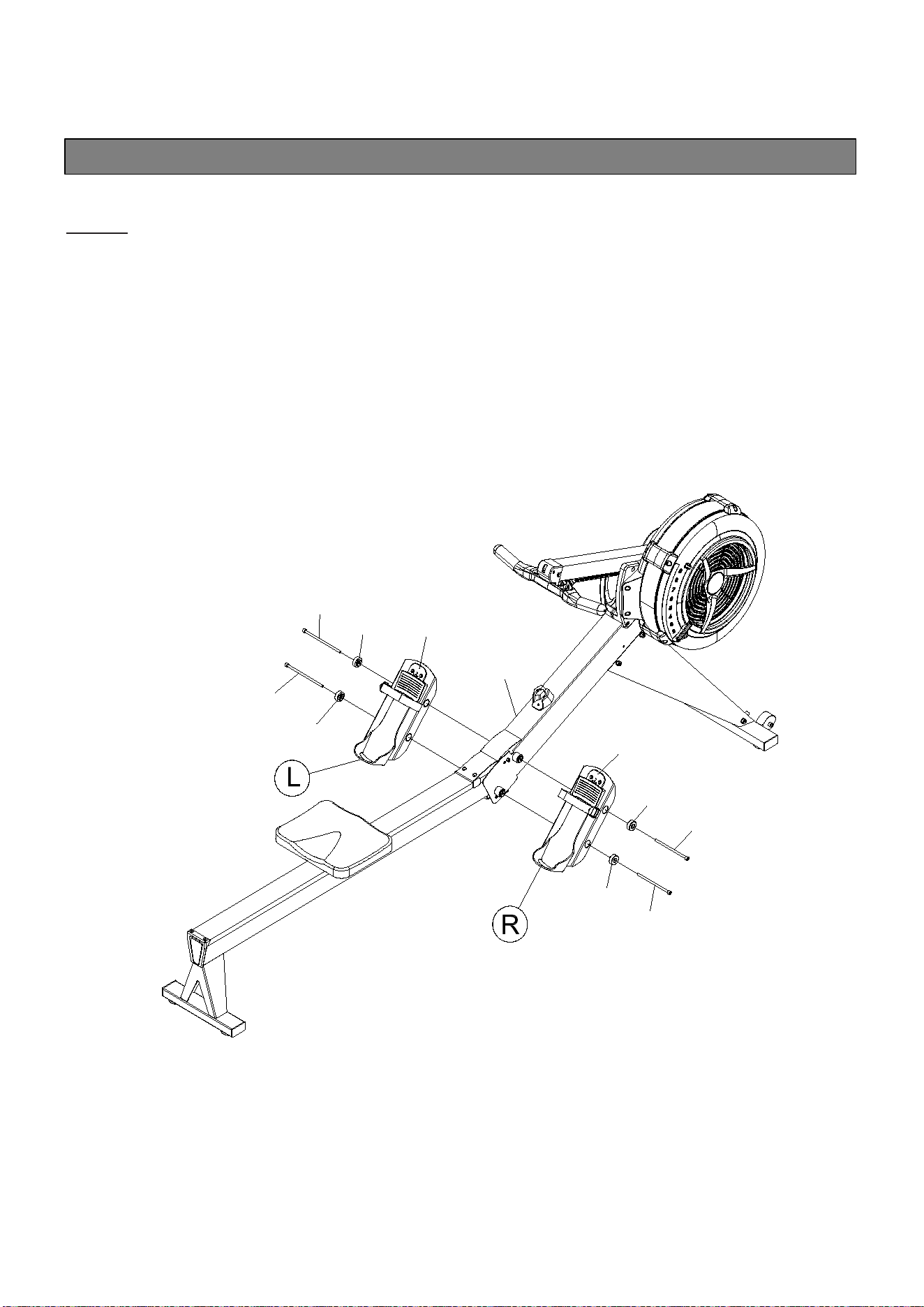
STEP 6
Attach Pedal Support Plates(5) to the Main Frame(1) using: 4 PCs of M10X160mm Socket
Head Cap Screw(84) and Foot Pedal End Cap(9).
NOTE: Fully tighten bolts at end of this step.
45L
45R
84
84
84
9
9
9
1
84
9
ASSEMBLY INSTRUCTIONS
10
ASSEMBLY INSTRUCTIONS
STEP 7
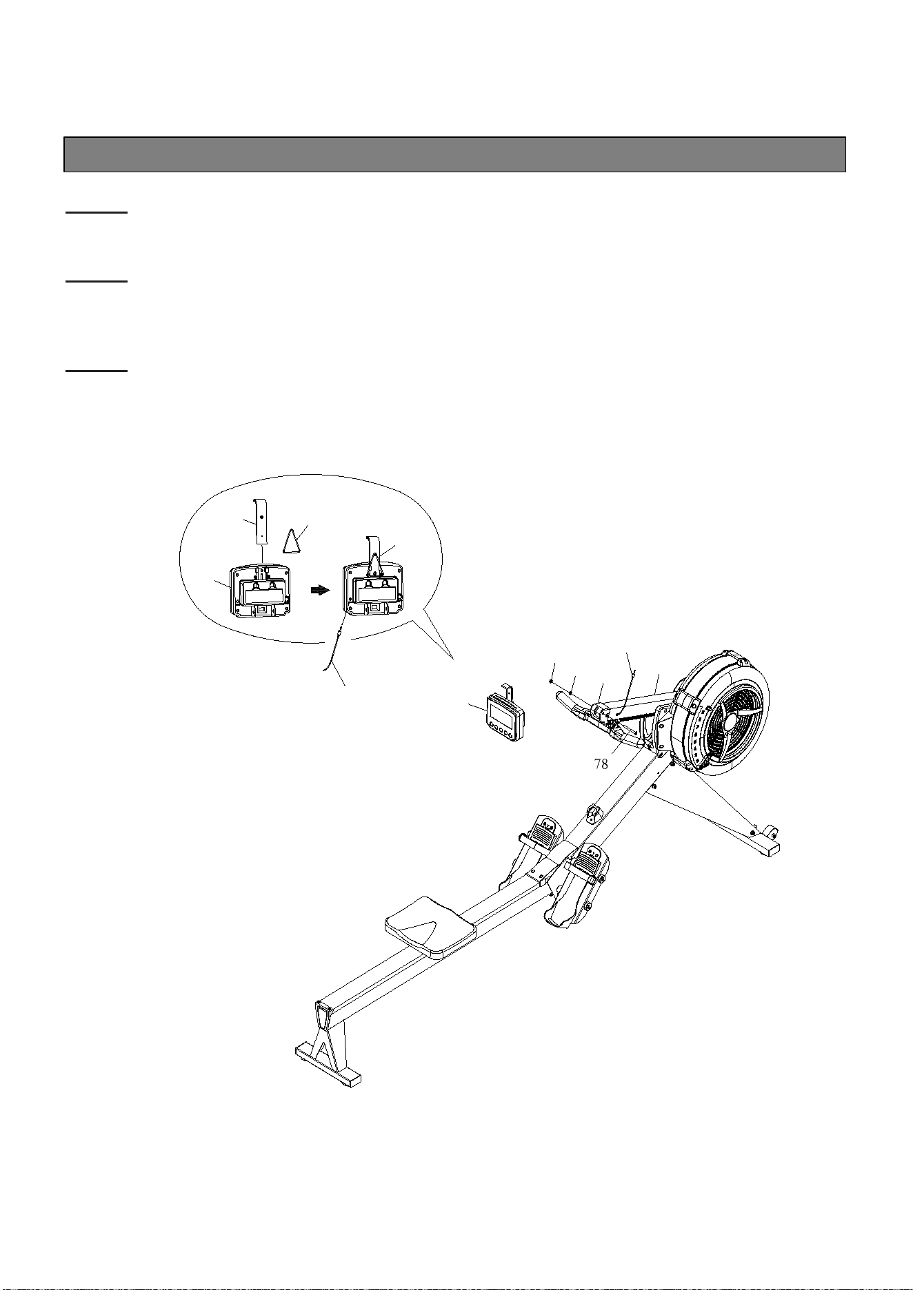
Attach Cell Phone Bracket(20) to the Console Monitor(19) using Rubber Band(21).
STEP 8
Attach the Console Monitor(19) to the Console Mounting Bracket(69) using: M8X75mm
Button Head Cap Screw(78), M8 Flat Washer(79), and M8 Nylon Lock Nut(80).
STEP 9
Connect Sensor Cable(23) into the back of the Console Monitor(19a).
80
79
6
19
69
23
21
20
19
21
23
COMPUTER INSTRUCTIONS
11
COMPUTER INSTRUCTIONS
Your ROWER utilizes an air fan system to create resistance for your workout. We recommend
that you use this computer console to vary your workout from session to session and note your
progress toward your fitness goals. When used regularly in this way, the computer console can
become an important source of motivation and interest which will help keep you on track.
I. INITIAL SETUP
POWER ON:
- Move the handlebar to start exercising in Quick start program or press any button to go into
IDEL mode.
POWER OFF:
- In IDLE mode, automatically shuts off after 20 seconds of inactivity.
- When running an Interval Program, automatically shuts off after 2 minutes of inactivity
- In all other programs, automatically shuts off after 30 seconds of inactivity.
METRIC & STANDARD UNIT:
- The initial factory setting is in “KM”. To toggle between Miles and Kilometers, press and hold
“UP” and DOWN” buttons when console in IDLE mode, it will display flashing “KM” & “MILE”.
Press “UP” or “DOWN” arrows to select “KM” or “MILE” and then press “ENTER” to confirm.
BATTERY INSTALLATION:
- Console operates on 2 Size C batteries. The battery compartment is on the back of the
console. Battery is included.
- When there’s no batteries installed, console can still work in Quick start program.

COMPUTER INSTRUCTIONS
12
COMPUTER INSTRUCTIONS
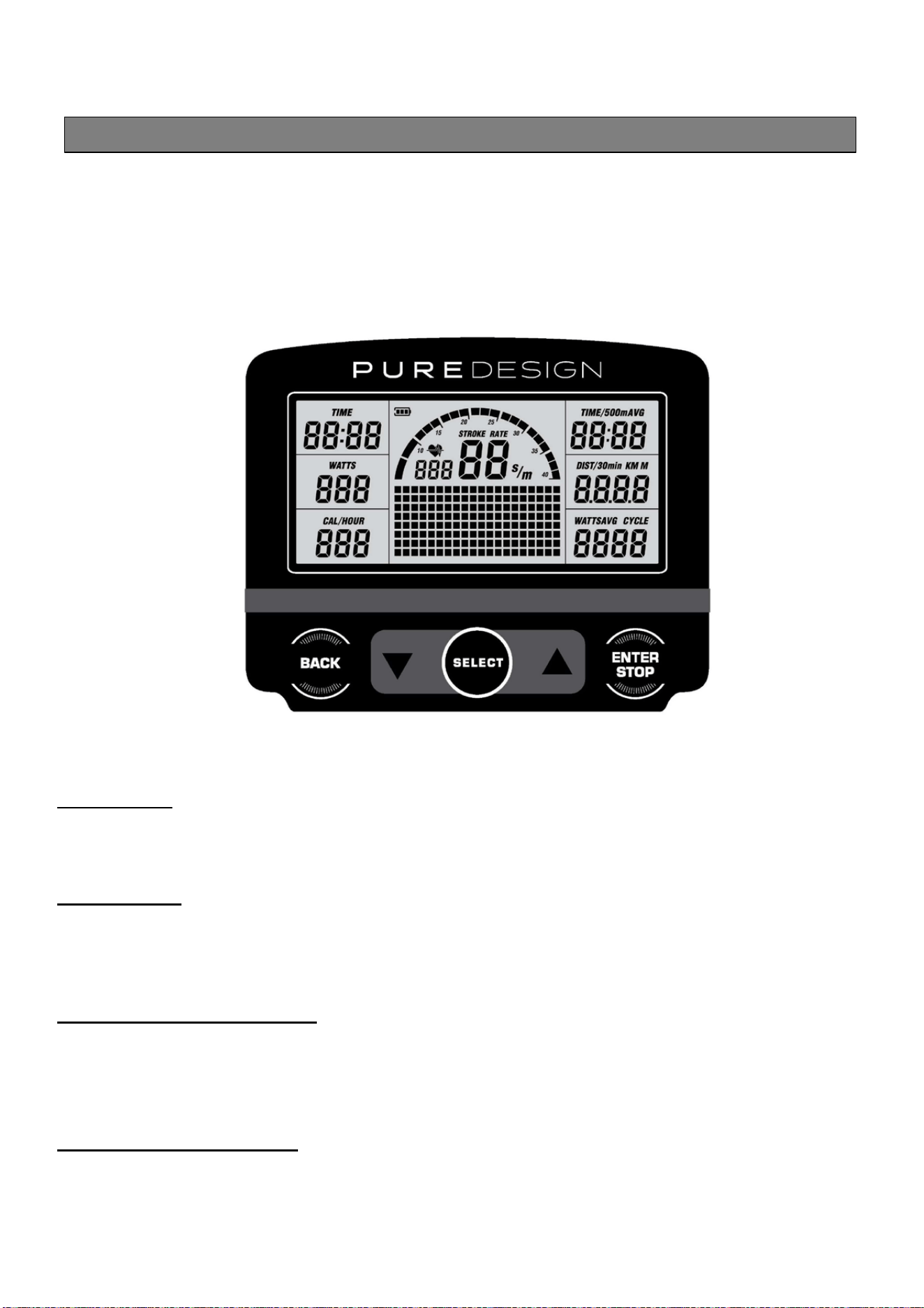
II. FUNCTION BUTTONS
SELECT BUTTON:
- In IDLE mode, press and release SELECT to cycle through each program option. Stop on the
program of your choosing. You can preset target values for DISTANCE, TIME, and CALORIES,
GAME, or select an Interval Program of 20/10, 10/20, or 10/10.
NOTE: Default exercising mode is Quick start program.
(UP BUTTON):
- Press to increase the preset values. Press the button and hold it down, the presetting value
will go faster, release the button to stop.
-
(DOWN BUTTON):
- Press to decrease the preset values. Press the button and hold it down, the presetting value
will go faster, release the button to stop.
BACK BUTTON:
- When selecting the programs, press the button to return to the previous program.
- When you finish a running program, press the button to jump into the IDEL mode.
ENTER/STOP BUTTON:
- When selecting the programs and presetting target values, press the button to confirm.
- Press the button and hold it down for three seconds to reset all functions to zero and restart
the computer.
- During exercise, when back light is turned off, the first pressing of this button will turn on the
back light. When the back light is still lit, press the button a second time to pause the counting
of all function values. Press the button a third time to restart the workout and continue of the
counting of all function values.
COMPUTER INSTRUCTIONS
13
COMPUTER INSTRUCTIONS
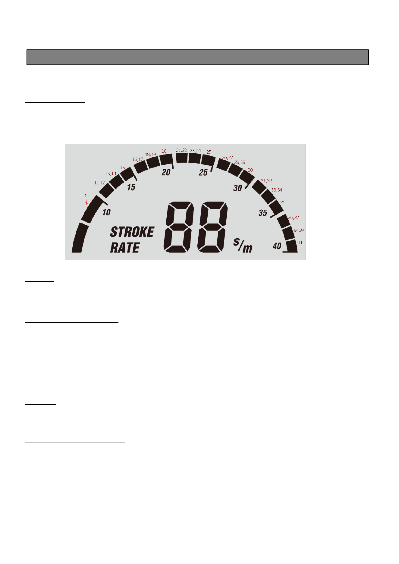
III. CONSOLE DISPLAY
STROKE RATE:
- Display the current stroke per minute during exercise.
- The lightened up semi-circle equals to the stroke rate that displayed in numbers. The more
grids it shows, the higher your stroke rate is.
PULSE:
- Display the heart rate from 40 to 220 beats per minute during exercise. To use this function,
the user must wear Heart Rate Chest Strap.
TIME & TIME/500m AVG:
- Display range: 00:00 ~ 99:59 minutes.
- The workout time is accumulated when under any workout mode.
- Display flashing “00:00” for presetting the TIME (countdown) program. Time can be set from
1:00 to 99:00 minutes.
- Time cannot be saved under 10/10 INTERVAL program. Setting range is 10 ~ 99.
- The time/500m is the average time per hour for reaching distance of 500 meters.
WATTS:
- Display range: 0 ~ 999 watts.
- Display the amount of power generated at any moment during the workout.
DISTANCE & DIST/30MIN:
- Display range: 0 ~ 9999 meters. It’s accumulated in cycle mode that numbers go back to 0 if
the distance exceeds 9999 meters.
- The workout distance is accumulated when under any workout mode.
- Display flashing “500” for presetting DISTACNE (countdown) program. The target distance
value can be set from 500 to 9999 meters.
- The distance/30min is the estimated distance for 30 minutes with the current stroke rate.

COMPUTER INSTRUCTIONS
14
CALORIES/HOUR:
- Display range: 0 ~ 9999 meters. It’s accumulated in cycle mode that numbers go back to 0 if
the distance exceeds 9999 meters.
- The workout distance is accumulated when under any workout mode.
- Display flashing “500” for presetting DISTACNE (countdown) program. The target distance
value can be set from 500 to 9999 meters.
- The distance/30min is the estimated distance for 30 minutes with the current stroke rate.
WATTS AVG:
- Display the average watts during the exercise.
CYCLE:
- Display only in INTERVAL program.
- Display flashing “8” for presetting the target rounds of exercise in INTERVAL program. The
target cycle value can be set from 1 to 99 rounds.
LOW BATTERY REMINDER:
- Display battery symbol only when the battery is low.
IV. PROGRAMS
The Console Monitor has eight programs: QUICK START, TIME (countdown), DISTANCE
(countdown), CALORIES (countdown), GAME, and INTERVAL PROGRAMS of 20/10, 10/20, &
10/10.
Press “Select” to change workout program according to the following sequence: Quick Start
Distance Time Calories Game 20/10 Interval 10/20Interval 10/10 User Setting
Interval
1. QUICK START PROGRAM
- To Quick Start the program, you can pull on the Handlebar(3) to start. All function values for
the console will count up.
- Press “STOP” button once to temporarily stop counting all values (Pause function). Pull the
Handlebar (3) again to continue the counting. Long press “STOP” button to delete all counting
data.
- For Quick Start and all three countdown programs, press “SELECT” button to choose the data
displayed in the same display window, including Time & Time/500m AVG.
COMPUTER INSTRUCTIONS
15
COMPUTER INSTRUCTIONS
- For the other seven programs, press “BACK” button to enter IDLE mode. Or press and hold
“ENTER/STOP” button for over 3 seconds to re-start the console. Use “SELECT” button to
toggle between programs. Use “UP” and “DOWN” buttons to adjust the value and press
“ENTER/STOP” to confirm.
2. DISTANCE (Countdown) PROGRAM
- During the workout, the “DISTANCE” program will count down from preset value.
- The program will start once the user pulls the Handlebar(3). When the program is finished, the
monitor will show “WINNER” with an audible alarm. Press the “BACK” button to go to the IDLE
mode.
3. TIME (Countdown) PROGRAM
- During the workout, the “TIME” program will count down from preset value. The program will
start once the user pulls the Handlebar(3). When the program is finished, the monitor will end
with an audible alarm. Press “BACK” button to go to the IDLE mode.
4. CALORIES (Countdown) PROGRAM
- During the workout, the “CALORIES” program will count down from preset value. The program
will start once the user pulls the Handlebar(3). When the program is finished, the monitor will
show “END” with an audible alarm. Press “BACK” button to go to the IDLE mode.
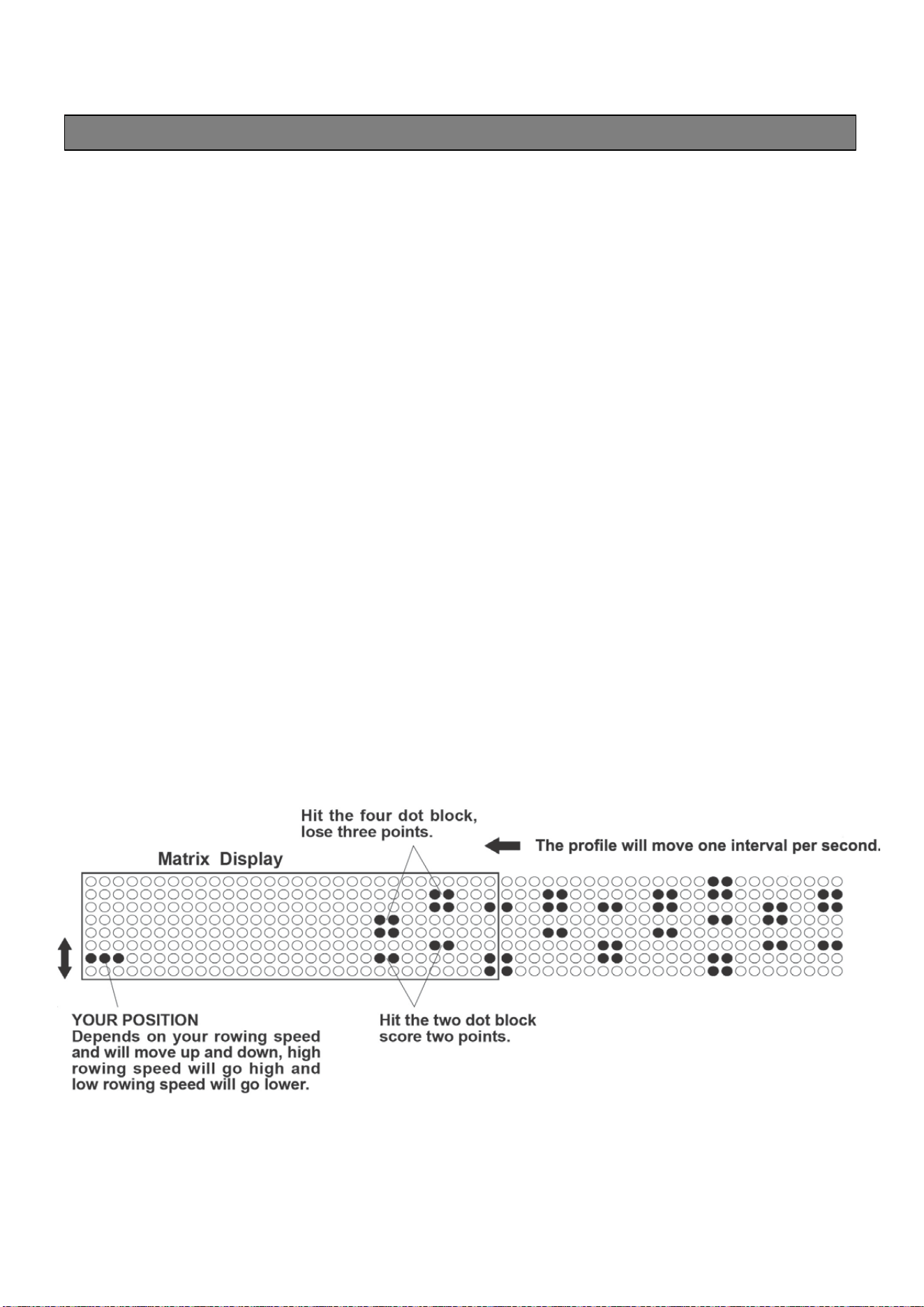
5. GAME PROGRAM
- When the “GAME” program is selected, the program will start once the user pulls the
Handlebar. There is no presetting value to be entered. When the program is finished, the
monitor will show your score with an audible alarm. Press the “BACK” button to go to the IDLE
mode.

COMPUTER INSTRUCTIONS
16
COMPUTER INSTRUCTIONS
6. 20/10 INTERVAL PROGRAM
- When it is in the “20/10 INTERVAL” program, the console monitor will display flashing “8” for
presetting value of cycle. “20” is 20 seconds for exercising, and “10” is 10 seconds for resting.
Then user can use “UP” and “DOWN” buttons to input the value from 1 to 99. The user will
workout for 20 seconds and then rest for 10 seconds. When the program is finished, the
monitor will end with an audible alarm. Press the “BACK” button to go to the IDLE mode.
7. 10/20 INTERVAL PROGRAM
- When it is in the “10/20 INTERVAL” program, the console monitor will display flashing “8” for
presetting value of cycle. Then user can user “UP” and “DOWN” buttons to input the value
from 1 to 99. User will workout for 10 seconds and then rest for 20 seconds. The program will
start once the user pulls the Handlebar(3). When the program is finished, the monitor will end
with an audible alarm. Press the “BACK” button to go to the IDLE mode.
8. 10/10 INTERVAL PROGRAM
- When it is in the “10/10” INTERVAL” program, the console monitor will display flashing “8” for
presetting value of cycle. Then user can use “UP” and “DOWN” buttons to input the value from
1 to 99 for number of cycle, workout time, and rest time. The program will start once the user
pulls the Handlebar(3). When the program is finished, the monitor will end with an audible
alarm. Press the “BACK” button to go to the IDLE mod
17
OPERATIONAL INSTRUCTIONS
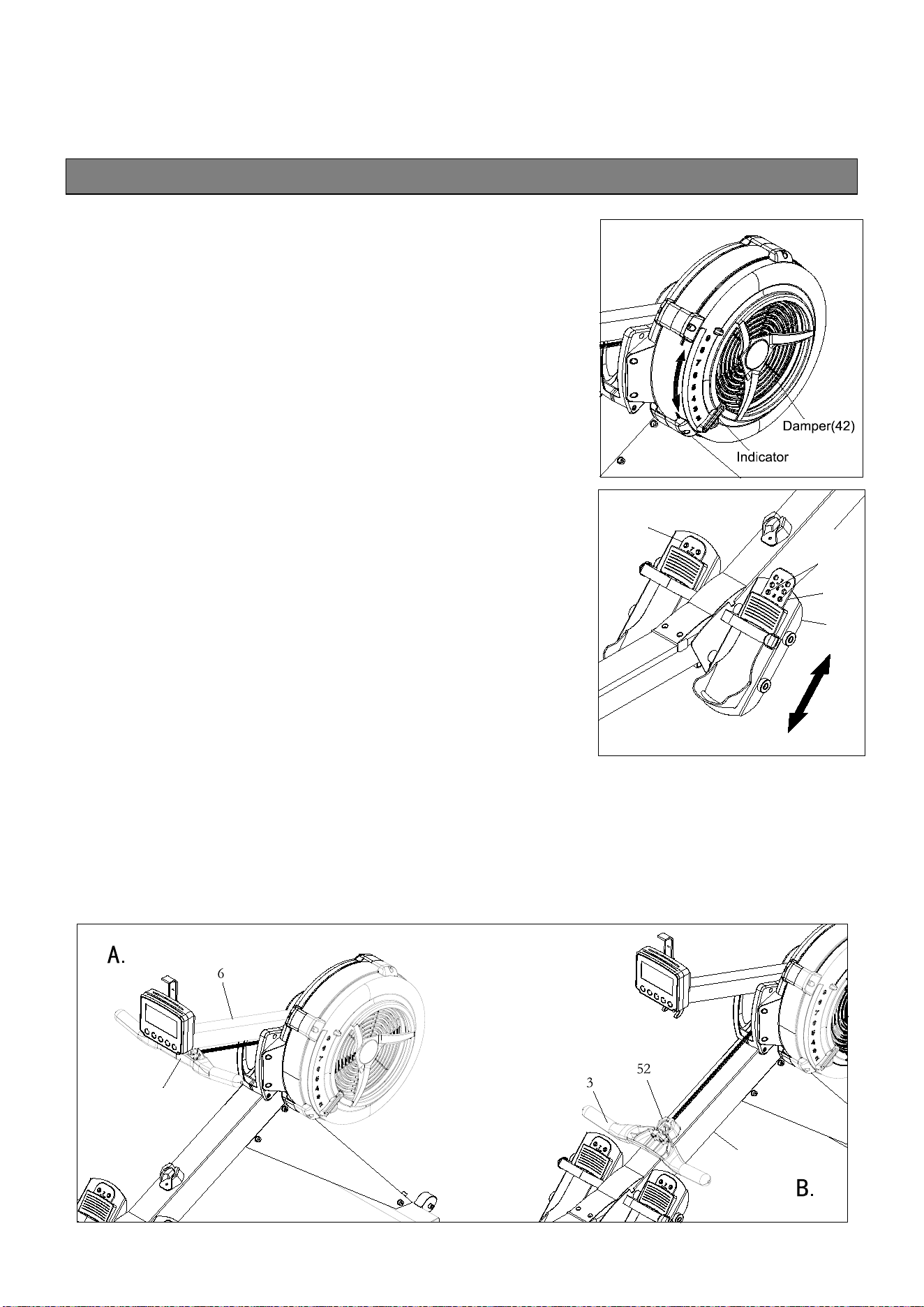
I. LOAD ADJUSTMENT
There is a Damper(42) built into the Right Fan
Shroud(43). Move the Indicator in the Damper(42) to point
to the numbers on the Right Fan Shroud(43) to adjust the
load. There are settings from 1 to 9. Setting #1 will
provide the lowest resistance. Setting #9 will provide the
highest resistance.
II. LOAD ADJUSTMENT
The position of the Foot Pedal(45) can be adjusted. Refer
to
the illustration. Pull the Foot Pedal(45) out from the two
bulges in the Pedal Support Plate(5), then lower or
raise the Foot Pedal(45) to the desired position. Lock the
Foot Pedal(45) in position by pressing the adjustment
holes of the desired position onto the two bulges.
Refer to the numbers on the Foot Pedal(45) to make sure
that
Foot Pedal(45) are adjusted on the same position
on both sides.
III. HANDLEBAR POSITION
The Handlebar(3) can be placed on the hook in the Console Monitor Post(6), refer to illustration
A. Or, you can place the Handlebar(3) on the Handlebar Holder (52) as shown in illustration B.
5
45
45
B u lg e s
1
3
18
OPERATIONAL INSTRUCTIONS
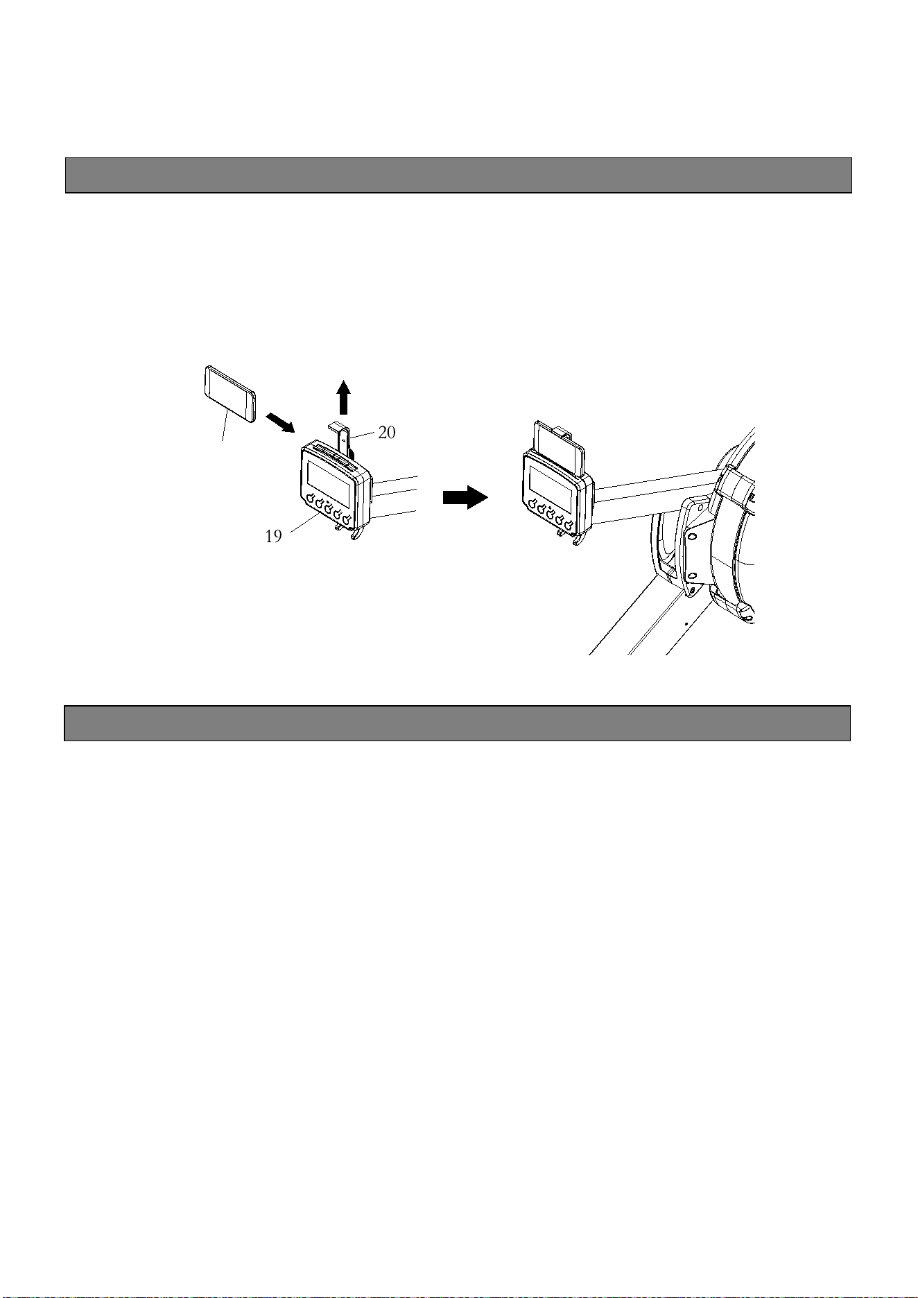
USING THE CELL PHONE BRACKET
The Cell Phone Bracket(20) can move up and down. Move up the Cell Phone Bracket(20),
then slide the Cell Phone into the gap between the Cell Phone Bracket(20) and
the Console Monitor(19). Move down the Cell Phone Bracket(20) to clip the Cell Phone in
position.
MAINTENANCE
The safety and integrity designed into the ROWER can only be maintained when the ROWER
is regularly examined for damage and wear. Special attention should be given to the following:
1.
Pull on the Handlebar(3) and verify that the Magnetic System provides tension and the seat
travel is smooth and stable.
2.
Clean the roller tracks in the Stainless Steel Rail(14) with an absorbent cloth.
3.
Verify that all nuts and bolts are present and properly tightened. Replace missing nuts and
bolts.
Tighten loose nuts and bolts.
4.
Check the condition of the
Chain(36)
.
Replace the
Chain(36)
if it is cracked or broken.
5.
It is the sole responsibility of the user/owner to ensure that regular maintenance is performed.
6.
Worn or damaged components must be replaced immediately or the ROWER
removed from service until repair is made.
7.
Only Stamina Products supplied components should be used to maintain/repair the
ROWER
.
8.
Keep your
ROWER
clean by wiping it off with an absorbent cloth after use.
Cell Phone
19
MAINTENANCE
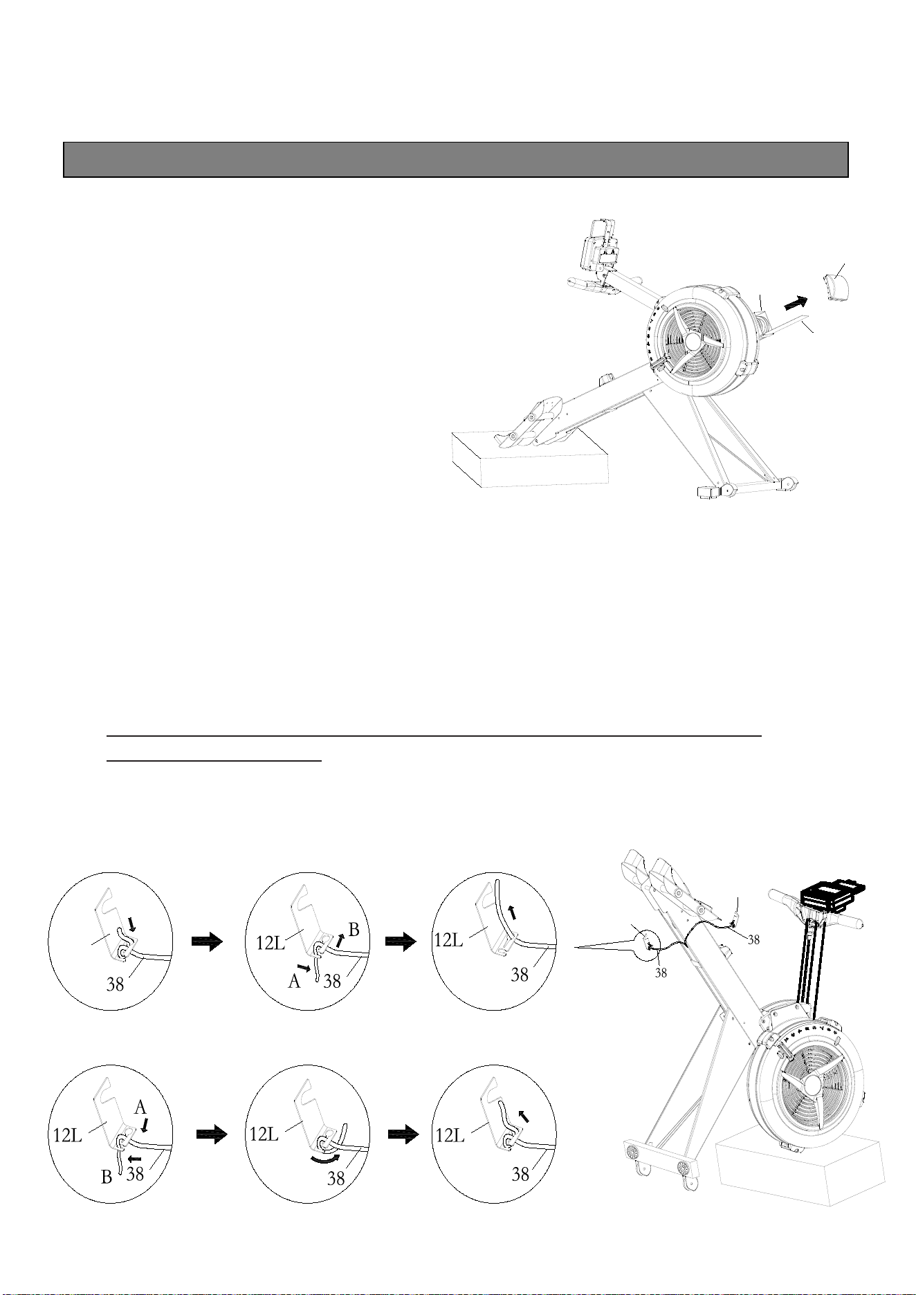
BUNGEE CORD ADJUSTMENT
Over time, about 250,000 strokes on
Handlebar(3), your Bungee Cord (38)
may stretch. Follow the following
process to adjust:
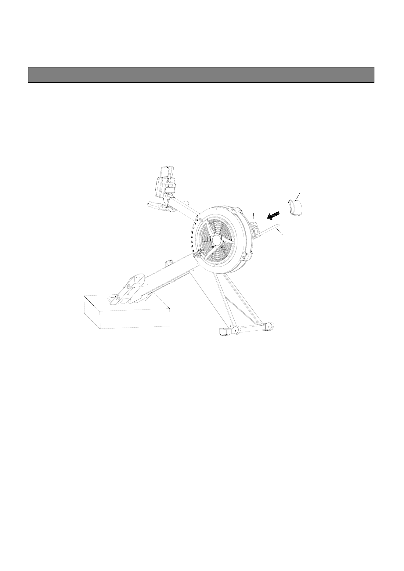
1. Position the Main Frame
Assembly(1) as shown in the
illustration. Remove the Main
Frame Top Cap(68) from the
Main Frame(1). Slide out the
Bottom Cover(70) from the Main
Frame(1).
2. Position the Main Frame Assembly(1) as shown in the below illustration. Unhook the
Left Bungee Cord Hook(12L) from the Main Frame(1). Make a mark on the Bungee Cord
(38) to move the hook forward 2 inches (5 cm). Refer to View 1 to View 3 to untie the
Bungee Cord(38) from the Left Bungee Cord Hook(12L), and move the hook forward 2
inches (5cm). Refer to View 4 to View 6 to retie the Bungee Cord(38) to the Left Bungee
Cord Hook(12L). Hook the Left Bungee Cord Hook(12L) back into the Main Frame(1) and
push the hook to the left side to touch the inner wall of the Main Frame(1).
NOTE: Always use two hands with a secure grip
when re-attaching the Bungee
Cord Hooks (12L & 12R).
Unhook the Right Bungee Cord Hook(12R) from the Main Frame(1). Do the same
as above to adjust the Bungee Cord(38) on the right side.
68
70
1
12L
12R
12L
1.
2.
3.
4.
5.
6.
20
MAINTENANCE
3. Position the Main Frame Assembly(1) as shown in the illustration. Slid the Bottom
Cover(70) back into the Main Frame (1).Press the Main Frame Top Cap(68) into the
Main Frame(1).
68
70
1
21
STORAGE
1.
To store the ROWER, simply keep it in a clean dry place.
2.
To avoid damage to the electronics, remove the batteries from the Console Monitor(19) before storing
the ROWER for one year or more.
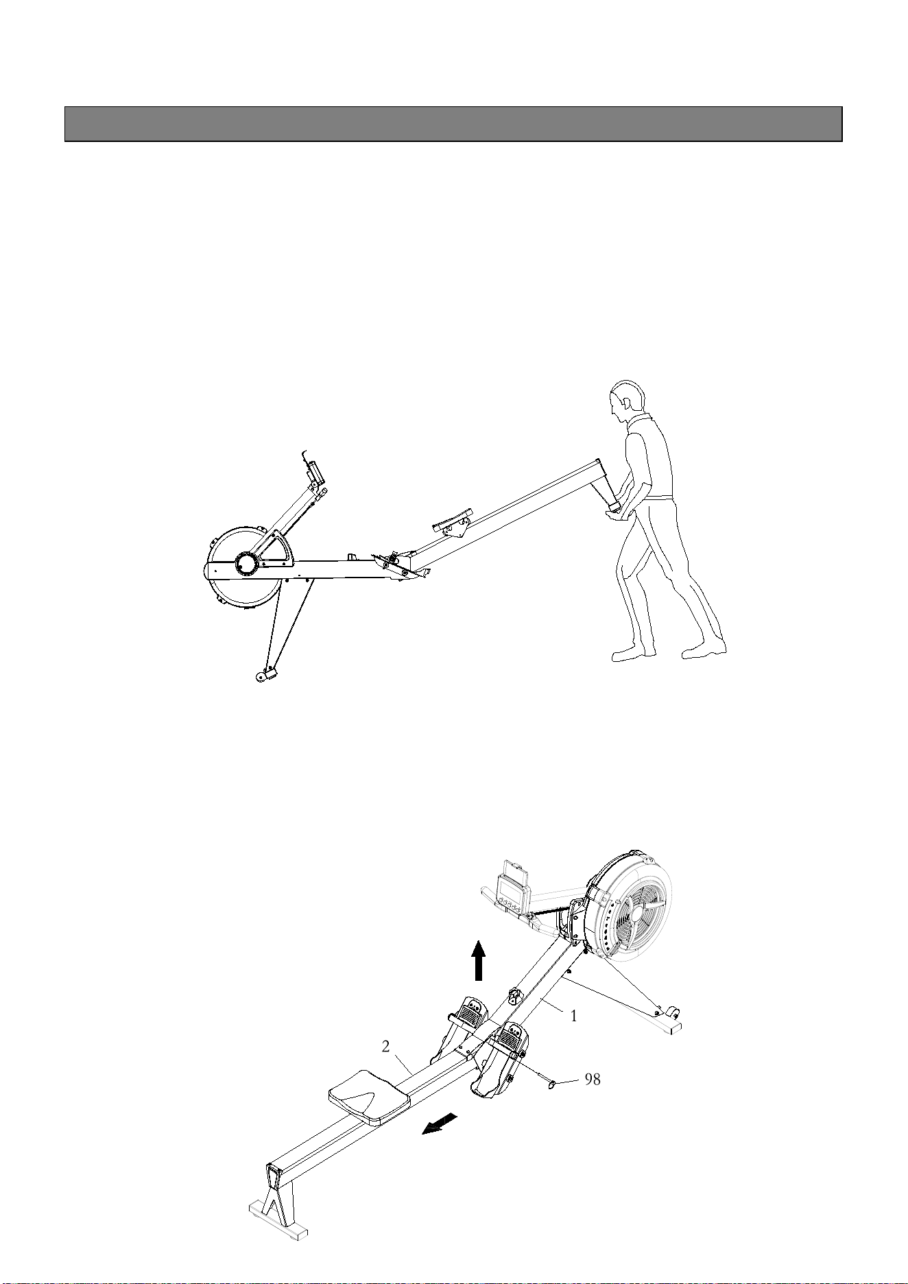
3.
Move the ROWER with the Transport Wheels(66) on the Front Stabilizer(4). Lift the Rear Stand of
the Rail Frame(2) to move the ROWER. Refer to the illustration below. Do not use the Seat(51) to
move the ROWER. The Seat(51) will move and the Seat Carriage(10) may pinch your hand or
fingers.
4.
The Main Frame(1) and the Rail Frame(2) can be separated to minimize the unit size for
storage. Remove the Pull Pin(98) from the Main Frame(1). Lift up the Main Frame(1) and pull
out the Rail Frame(2) to separate. Insert the Pull Pin(98) back to the hole in the Main
Frame(1) for storage.
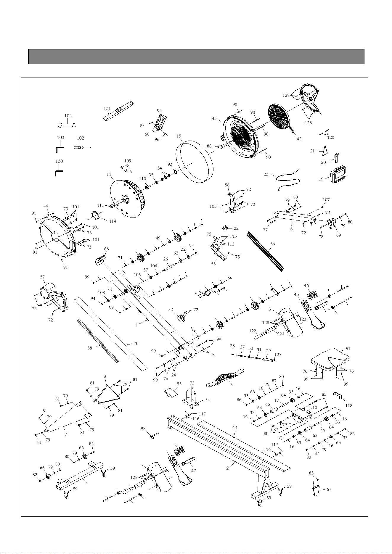
22
PRODUCT PARTS DRAWING
39
25
56
12
12
25
25
39
39
40
48
48
41
41
41
41
50
50
71
99
99
99
76
76
76
76
71
39
41
41
76
76
41
41
9
9
84
84
5
45
46
121
122
123
9
84
9
84
47
13
40
125
18
74
76
92
100
126
79
79
129
129
129
129

23
PARTS LIST
PART#
DESCRIPTION
QTY
1
Main Frame
1
2
Rail Frame
1
3
Handlebar
1
4
Front Stabilizer
1
5
Pedal Support Plate
2
6
Console Monitor Post
1
7
Front Support Leg (Left)
1
8
Front Support Leg (Right)
1
9
Foot Pedal End Cap
4
10
Seat Carriage
1
11
Fan
1
12
Bungee Cord Hook
2
13
Chain Bracket
1
14
Stainless Steel Rail
1
15
Perforated Steel Mesh
1
16
Spacer, ø8.2xø12x3.2mm
6
17
Spacer,
ø
8.2x
ø
12x71.6mm
2
18
Spacer,
ø
6.2x
ø
10x15.5mm
1
19
Console Monitor
1
20
Cell Phone Bracket
1
21
Rubber Band
1
22
Generator
1
23
Sensor Cable
1
24
Shaft, M6xø11.8x79.5mm
2
25
Shaft, M6x
ø
10x76.5mm
3
26
Fan Axle
1
27
Hook Connector
1
28
Chain Connector
1
29
U Bolt
1

24
30
Inner Spacer
1
31
Outer Collar
1
32
Bearing 6003RS
1
33
Bearing 608ZZ
6
34
Bearing 6201RS
3
35
One Way Bearing HF2016
1
36
Chain
1
37
Sprocket
1
38
Bungee Cord
1
39
Bungee Cord Pulley
4
40
Chain Roller
2
41
Bearing 6000ZZ
8
42
Damper
1
43
Right Fan Shroud
1
44
Left Fan Shroud
1
45
Foot Pedal
2
46
Foot Pedal Holder
2
47
Pedal Strap
2
48
Spacer,
ø
10x
ø
16x30.5mm
2
49
Pulley Spacer, ø10xø16x26.5mm
1
50
Pulley Bushing
2
51
Seat
1
52
Handlebar Holder
1
53
Upper Joint Cover
1
54
Lower Joint Cover
1
55
Generator Base
1
56
Damper Cap
1
57
Left Side Cover
1
58
Right Side Cover
1
59
Foot Cap
4
60
Steel Plate
2
61
Bushing 6001
1

25
62
Bushing 6003
1
63
Guide Roller
2
64
Seat Roller
4
65
Roller Sleeve
2
66
Transport Wheel
2
67
Rail End Cap
1
68
Main Frame Top Cap
1
69
Console Mounting Bracket
1
70
Bottom Cover
1
71
Plastic Washer,
ø
10.2x
ø
14x1mm
3
72
Phillips Head Screw, M6x10mm
14
73
Lock Washer, Internal Tooth M6
7
74
Nylon Lock Nut, M6
3
75
Phillips Head Screw, ST4.2x10mm
3
76
Flat Washer, M6
17
77
Socket Head Cap Screw, M8x65mm
2
78
Button Head Cap Screw, M8x75mm
1
79
Flat Washer, M8
19
80
Nylon Lock Nut, M8
9
81
Socket Head Cap Screw, M8x12mm
8
82
Socket Head Cap Screw, M8x40mm
2
83
Phillips Flat Head Screw, M6x16mm
2
84
Socket Head Cap Screw, M10x160mm
4
85
Socket Head Cap Screw, M8x110mm
2
86
Button Head Cap Screw, M8x25mm
2
87
Lock Washer, M8
4
88
Phillips Head Screw, ST4.2x16mm
3
89
Phillips Head Screw, M5x12mm
4
90
Socket Head Cap Screw, M5x92mm
4
91
Hex Nut, M5
4
92
Chain Hook
2
93
Elastic Ring
1

26
94
Nylon Lock Nut, M10
2
95
Phillips Head Screw, ST4.2x6mm
6
96
Phillips Head Screw, M4x45mm
1
97
Hex Nut, M4
1
98
Pull Pin
1
99
Socket Head Cap Screw, M6x16mm
14
100
Phillips Head Screw, M6x30mm (Full Thread)
1
101
Phillips Head Screw, M6x10mm
7
102
Screw Driver
1
103
Allen Wrench, 6mm
1
104
Wrench
1
105
Hex Nut, M6
2
106
PU Spacer
2
107
Plug
1
108
Bearing, 6001RS
1
109
Balance Weight
3
110
Bearing Bushing
1
111
Socket Head Cap Screw, M4x12mm
3
112
Washer,
ø
12x
ø
3.5x1mm
2
113
Phillips Head Screw, ST3.5x12mm
2
114
Magnet
1
115
Warning Label
2
116
Stopper Bumper
2
117
Socket Head Cap Screw, M8x20mm
2
118
Stopper Bracket
1
119
Manual
2
120
EVA Pad
2
121
Pedal Strap Protector
2
122
Pedal Strap Stopper Plate
2
123
Phillips Flat Head Screw, M5x12mm
4
125
Phillips Head Screw, M6x30mm (Half Thread)
1
126
Spring Washer, M6
1

27
127
Nylon Nut (Thick)
2
128
Phillips Head Screw, ST4.2 x10mm
13
129
Phillips Head Screw, ST4.2 x19mm
12
130
Wrench, 8mm
1
131
Chest Belt
1