
1
IMPORTANT SAFETY INFORMATION
We thank you for choosing our product. To ensure your safety and health, please use this
equipment correctly. It is important to read this entire manual before assembling and using the
equipment. Safe and effective use can only be achieved if the equipment is assembled, maintained,
and used properly. It is your responsibility to ensure that all users of the equipment are informed of
all warnings and precautions.
1. Before starting any exercise program, you should consult your physician to determine if you
have any medical or physical conditions that could put your health and safety at risk or prevent
you from using the equipment properly. Your physician’s advice is essential if you are taking
medication that affects your heart rate, blood pressure, or cholesterol level.
2. Be aware of your body’s signals. Incorrect or excessive exercise can damage your health. Stop
exercising if you experience any of the following symptoms: pain, tightness in your chest,
irregular heartbeat, shortness of breath, lightheadedness, dizziness, or feelings of nausea. If
you do experience any of these conditions, you should consult your physician before continuing
with your exercise program.
3. Keep children and pets away from the equipment. The equipment is designed for adult use only.
4. Use the equipment on a solid, flat level surface with a protective cover for your floor or carpet.
To ensure safety, the equipment should have at least 2 feet (60 cm) of free space all around it.
5. Ensure that all nuts and bolts are securely tightened before using the equipment. The safety of
the equipment can only be maintained if it is regularly examined for damage and/or wear and
tear.
6. Always use the equipment as indicated. If you find any defective components while assembling
or checking the equipment, or if you hear any unusual noises coming from the equipment during
exercise, discontinue use of the equipment immediately and do not use until the problem has
been rectified.
7. Wear suitable clothing while using the equipment. Avoid wearing loose clothing that may
become entangled in the equipment.
8. Do not place fingers or objects into the moving parts of the equipment.
9. The maximum weight capacity of this unit is 300 lbs (135 kgs).
10. The equipment is not suitable for therapeutic use.
11. To avoid bodily injury and/or damage to the product or property, proper lifting and moving are
required.
12. Your product is intended for use in cool and dry conditions. You should avoid storage in
extreme cold, hot or damp areas as this may lead to corrosion and other related problems.
13. This equipment is designed for indoor and home use only; it is not intended for commercial use.
2
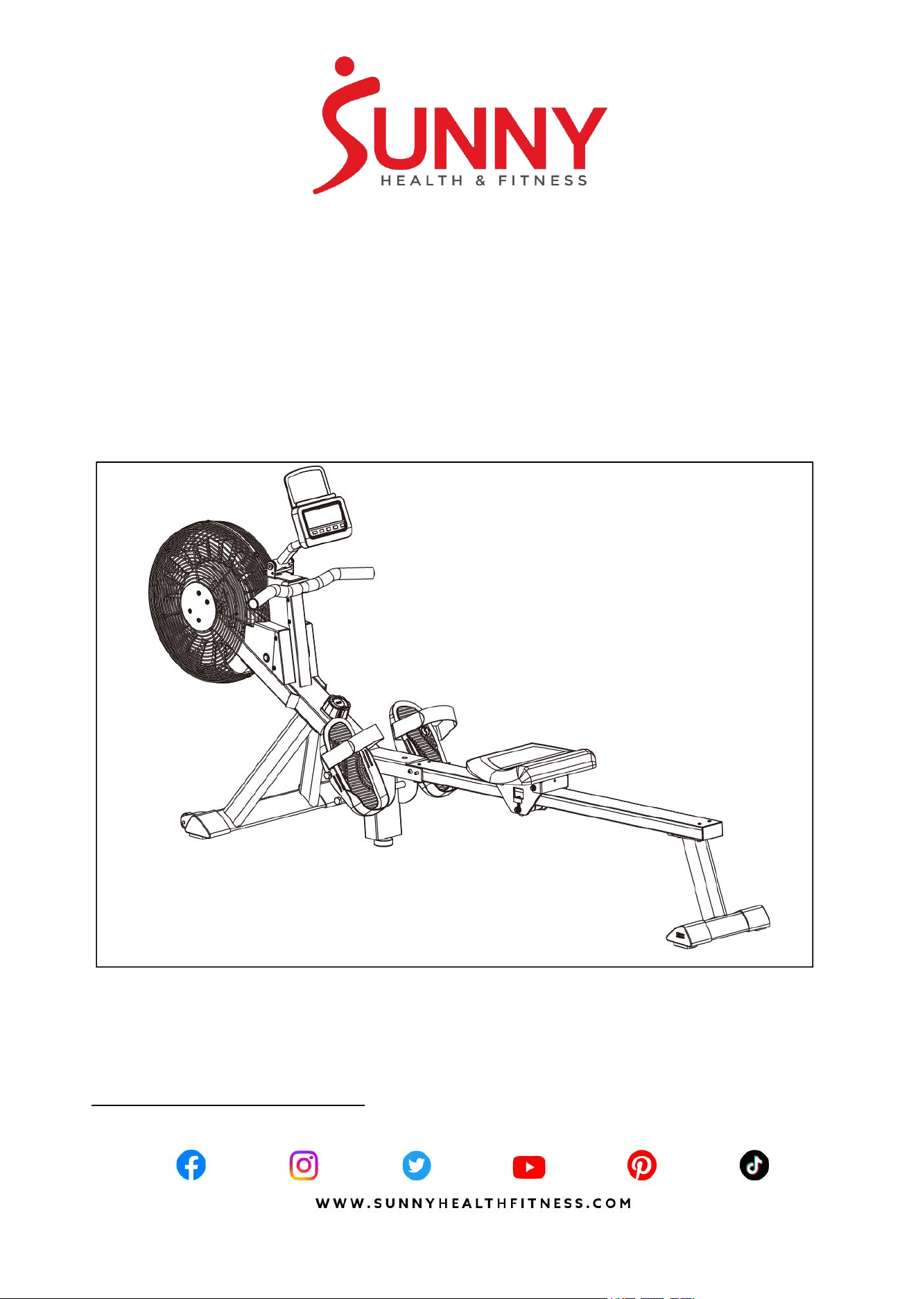
PRE-ASSEMBLY CHECK LIST
Before you start to assemble, please make sure all parts are included.
No.
Description
Spec.
Qty.
No.
Description
Spec.
Qty.
1
Main Frame
1
34
Right Pedal
1
2
Sliding Rail
1
39
Knob
M12*30
1
3
Front Stabilizer
1
50
Meter
BJHT109
1
4
Rear Stabilizer
1
A
Hardware Package
2
6
Seat
1
B
Manual
1
30
Foot Pad
1
C
Thank You Card
1
33
Left Pedal
1
D
Battery
2
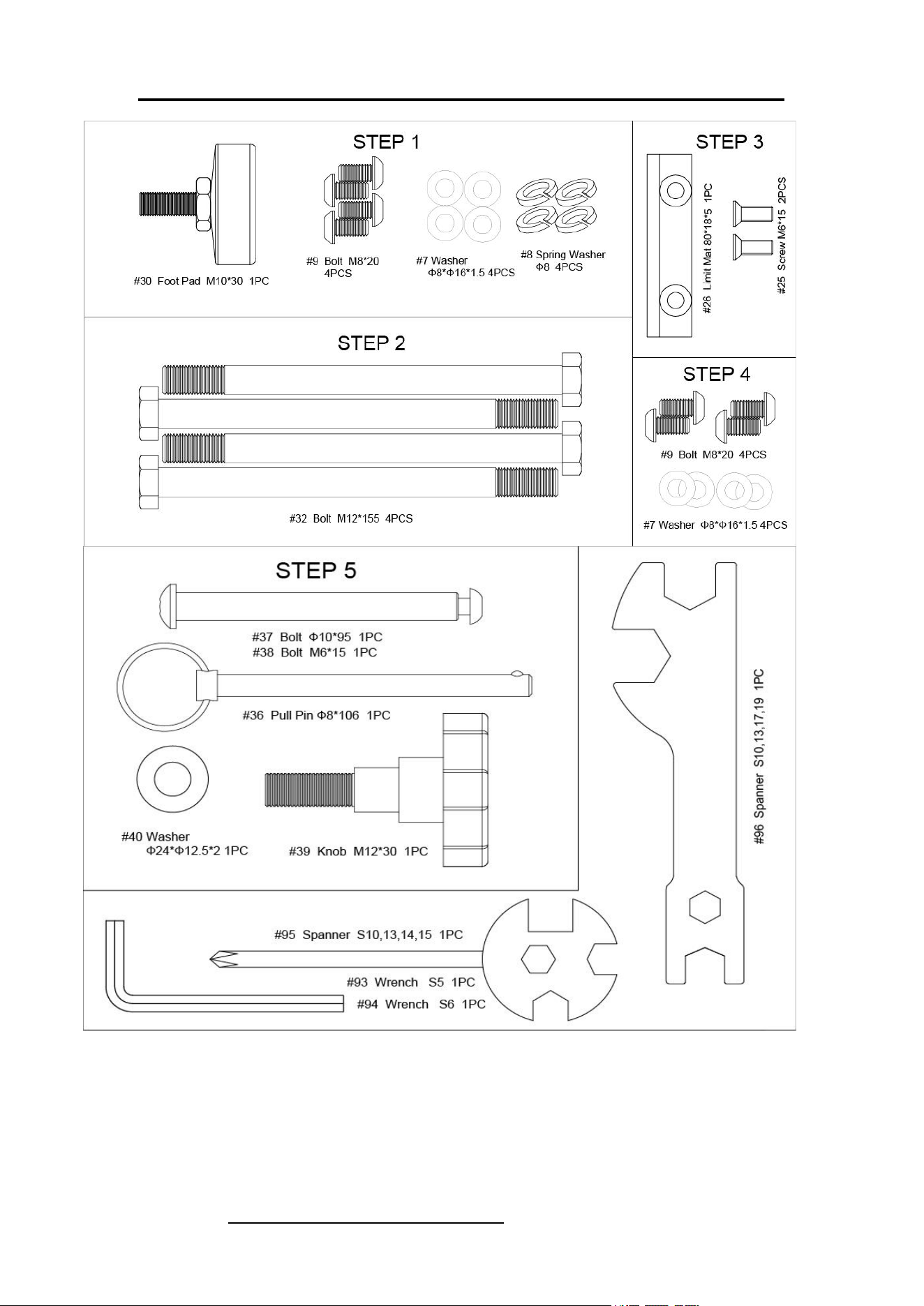
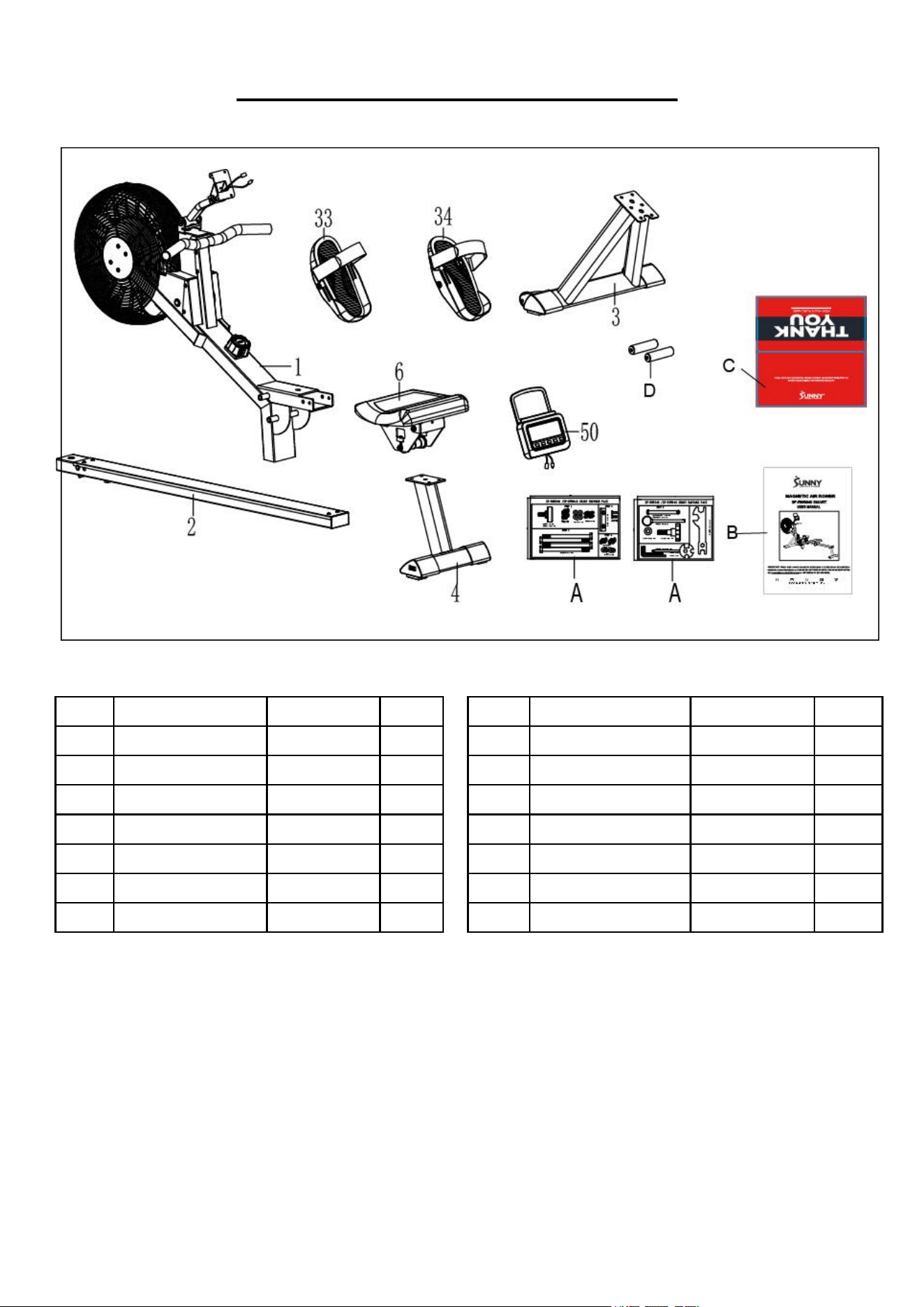
3
SF-RW5940 SMART HARDWARE PACKAGE
Ordering Replacement Parts (U.S. and Canadian Customers only)
Please provide the following information in order for us to accurately identify the part(s) needed:
The model number (found on cover of manual)
The product name (found on cover of manual)
The part number found on the “EXPLODED DIAGRAM” (pages 14-15) and “PARTS LIST”
(pages 16-17)
4
ASSEMBLY INSTRUCTIONS
We value your experience using Sunny Health and Fitness products. For assistance with parts or
troubleshooting, please contact us at support@sunnyhealthfitness.com or 1-877-90SUNNY
(877-907-8669).
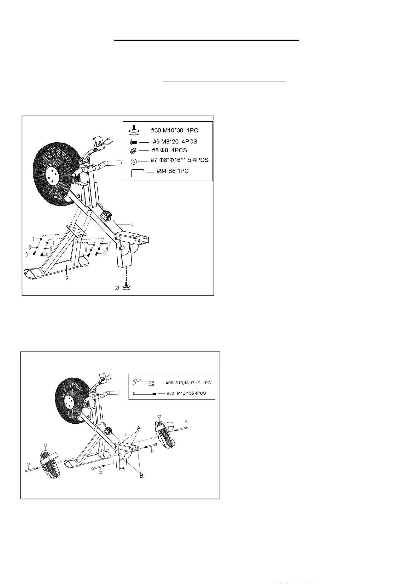
STEP 1:
Attach the Front Stabilizer (No. 3) to
the Main Frame (No. 1) using 4 Spring
Washers (No. 8) and 4 Washers (No.
7) and 4 Bolts (No. 9). Tighten and
secure with Wrench (No. 94).
Attach the Foot Pad (No. 30) to the
Main Frame (No. 1), tighten and secure
with your hand.
Notice: During installation, one person
should hold the machine steady while the
other performs the assembly. This can
prevent the machine from tipping or
causing injury.
STEP 2:
Insert 2 Bolts (No. 32) through the Left
& Right Pedals (No. 33 & No. 34) into
the upper hole at position A of the Main
Frame (No. 1). Tighten with Spanner
(No. 96).
Insert 2 Bolts (No. 32) into the bottom
hole at position B of the Main Frame
(No. 1). Tighten with Spanner (No. 96).
NOTE: The Left & Right Pedals (No. 33
& No. 34) should rest on the bottom
Bolts (No. 32) at position B.
5
We value your experience using Sunny Health and Fitness products. For assistance with parts or
troubleshooting, please contact us at support@sunnyhealthfitness.com or 1-877-90SUNNY
(877-907-8669).
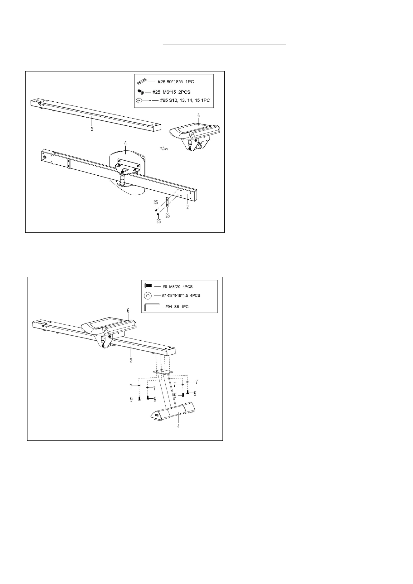
STEP 4:
Attach the Rear Stabilizer (No. 4) to the
Sliding Rail (No. 2) using 4 Bolts (No. 9)
and 4 Washers (No. 7). Tighten and
secure with Wrench (No. 94).
STEP 3:
Slide the Seat (No. 6) into the Sliding
Rail (No. 2).
Attach 1 Limit Mat (No. 26) to the Sliding
Rail (No. 2) using 2 Screws (No. 25).
Tighten and secure with Spanner (No.
95).
6
We value your experience using Sunny Health and Fitness products. For assistance with parts or
troubleshooting, please contact us at support@sunnyhealthfitness.com or 1-877-90SUNNY
(877-907-8669).
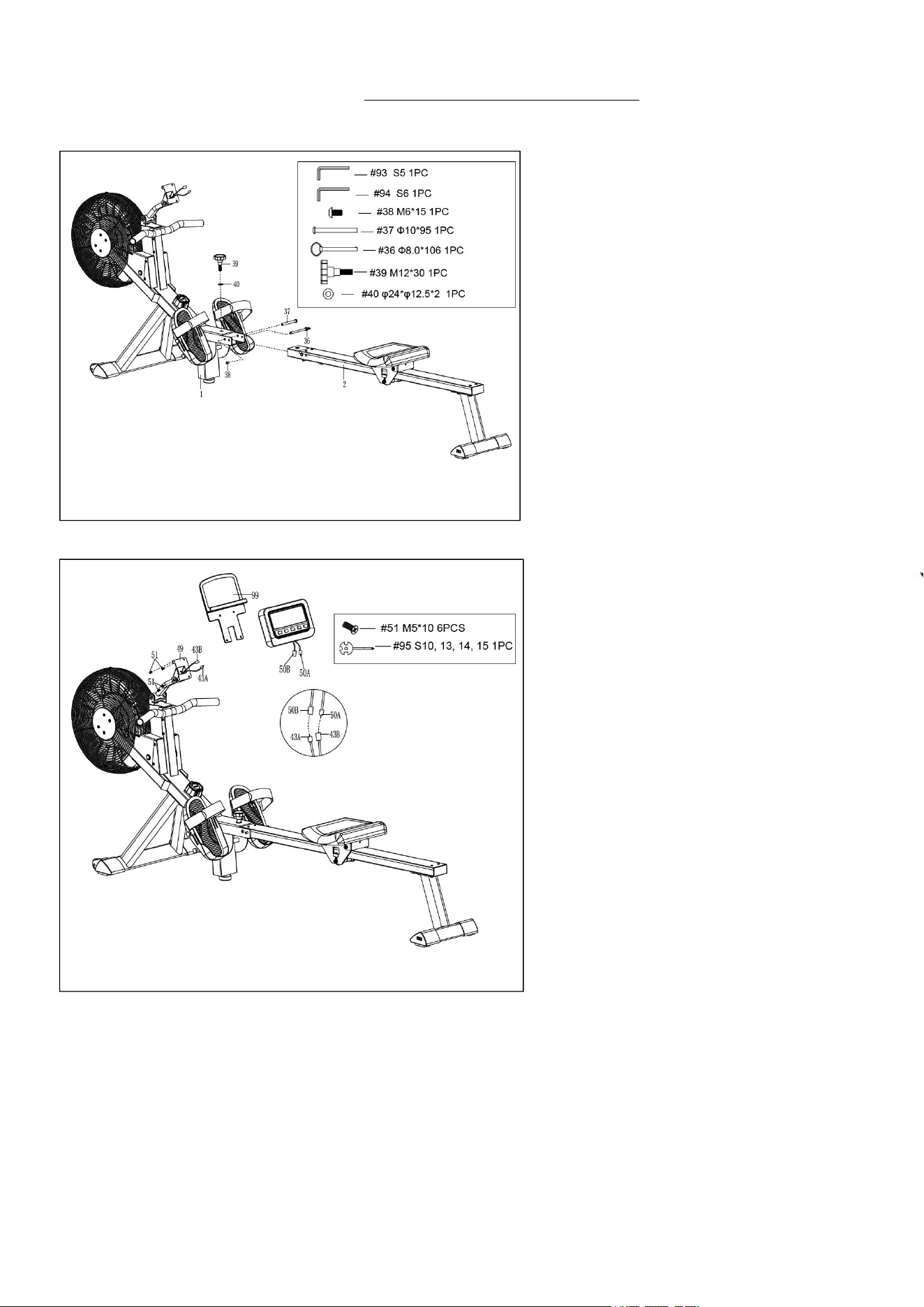
STEP 6:
Remove 4 Screws (No. 51) from the
back of the Tablet Holder (No. 99)
with the Spanner (No. 95)
Connect the Sensor Wire A (No. 43A)
to the Meter Wire B (No. 50B) and
connect the Sensor Wire B (No. 43B)
to the Meter Wire A (No. 50A). Then
attach the Tablet Holder (No. 99) and
the Meter (No. 50) to the Meter
Holder (No. 49) with 4 Screws (No.
51) that were removed. Tighten and
secure with Spanner (No. 95).
NOTE: Put all wires to the Meter
Holder (No. 49) before attaching the
Tablet Holder (No. 99) and the Meter
(No. 50) to the Main Frame (No. 1).
The assembly is complete!
STEP 5:
Attach the Sliding Rail (No. 2) to the
Main Frame (No. 1) using 1 Bolt
(No. 38) and 1 Bolt (No. 37). Tighten
and secure with Wrench (No. 93)
and Wrench (No. 94).
Next, secure the Sliding Rail (No. 2)
to the Main Frame (No. 1) using 1
Knob (No. 39) and 1 Washer (No.
40), then insert Pull Pin (No. 36).
7
ADJUSTMENTS &USAGE GUIDE
CAUTION! Moving parts, such as the seat, can cut and crush. Keep hands clear of the sliding
rail during use!
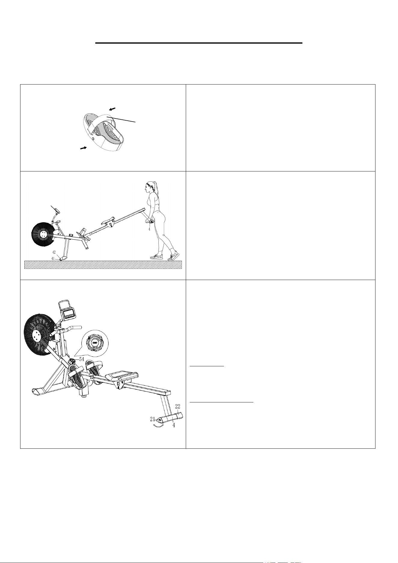
PEDAL STRAP ADJUSTMENT
The Pedal Strap (No. 35) is adjustable and can be
personalized to fit the user’s foot size.
MOVING THE ROWER
To move the rower, lift the Rear Stabilizer (No. 4)
up until the transportation wheels on the Left &
Right End Caps (No. 41 & No. 42) touch the
ground. With the transportation wheels on the
ground, you can transport the rower to the desired
location with ease.
ADJUSTING THE BALANCE AND RESISTANCE
Adjust the Left & Right End Caps (No. 21 & No.
22) on the Rear Stabilizer (No. 4) of the rower if
the rower is unbalanced during use.
Turn the Tension Control Knob (No. 54)
clockwise to increase the level of resistance.
Turn the Tension Control Knob (No. 54)
counter-clockwise to decrease the level of
resistance.
Tension levels are set at Level 1 being the lowest
and Level 16 being the highest.
35
8
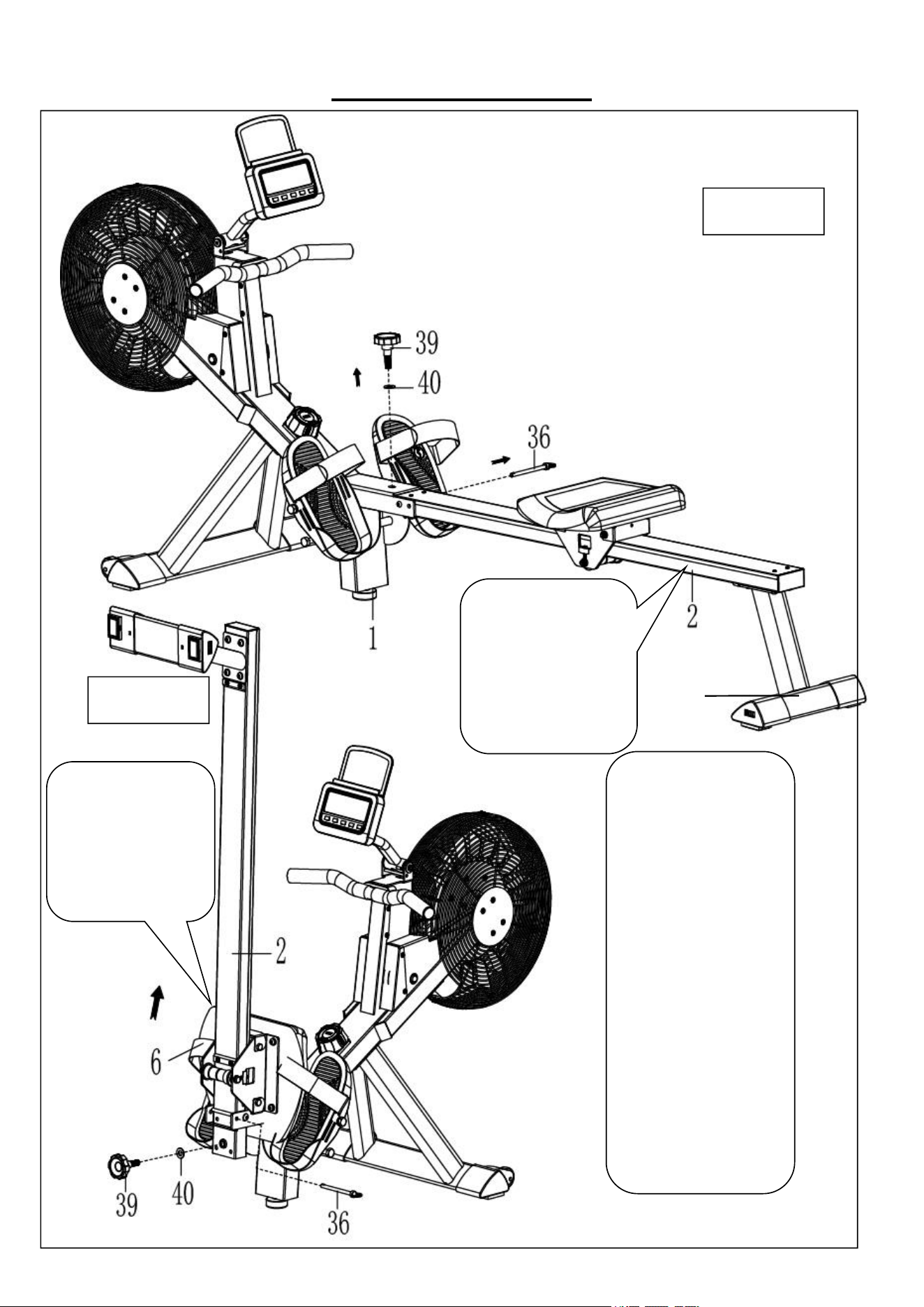
STORAGE GUIDE
CAUTION!
The Seat (No. 6) will
glide down when
folding the Sliding
Rail (No. 2)!
CAUTION!
Use caution when you
vertically fold the
Sliding Rail (No. 2)
as your head may
touch the Rear
Stabilizer (No. 4).
When not in use, you can
save space by folding the
Sliding Rail (No. 2).
Disassemble Knob (No.
39) and Washer (No. 40)
and pull out the Pull Pin
(No. 36). Fold the Sliding
Rail (No. 2) to vertical
angle (Figure A).
SAFETY NOTE: the Seat
(No. 6) will glide down
when folding the Sliding
Rail (No. 2).
Reinsert Pull Pin (No. 36)
into the hole on the Main
Frame (No. 1), then
tighten Knob (No. 39) and
Washer (No. 40) to Main
Frame (No. 1). (Figure B)
4
Figure A
Figure B
9
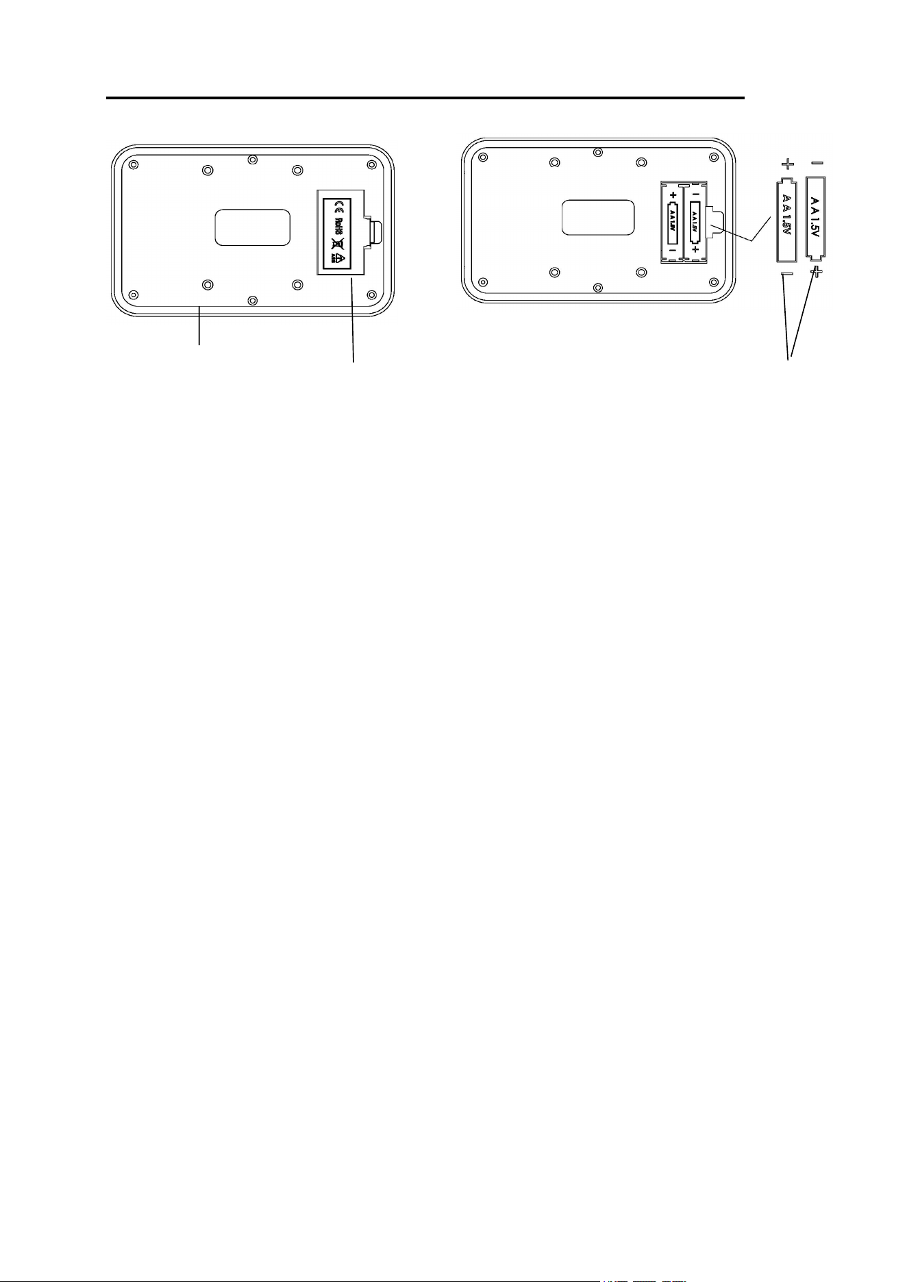
BATTERY INSTALLATION & REPLACEMENT
BATTERY INSTALLATION:
1. Take out 2 AA batteries from meter box.
2. Press the buckle of battery cover on the back of the Meter (No. 50), then remove battery cover.
3. Install 2 AA batteries into the battery case on the back of the Meter (No. 50). Pay attention to the
battery + and – poles before installing.
4. Press the buckle of battery cover, then put the battery cover back to the back of the Meter (No.
50).
BATTERY REPLACEMENT:
1. Press the buckle of battery cover on the back of the Meter (No. 50), then remove battery cover.
2. Remove the 2 old AA batteries in the battery case and install 2 new AA batteries into the battery
case on the back of the Meter (No. 50). Pay attention to the battery + and – poles before
installing.
3. Press the buckle of battery cover, then put the battery cover back to the back of the Meter (No.
50).
The replacement is complete!
NOTE: Always change both batteries at the same time. Do not mix battery types and do not mix old
and new batteries. Dispose batteries according to your state and regional guidelines.
50
Battery Cover
Battery
10
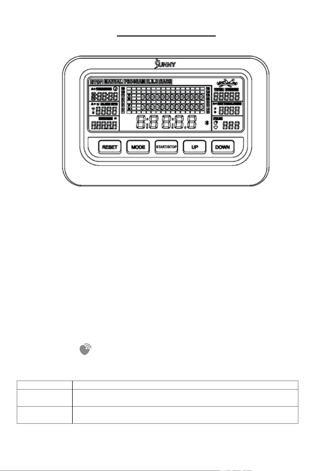
EXERCISE METER
TIME, TIME/500, SPM, DISTANCE, STROKES, TOTAL STROKES, CALORIES, WATT,
PULSE.
FUNCTION
TIME: The total working time since starting exercise. Display range: 0:00:00 ~ 9:59:59 (H:M:S).
TIME/500: The average time for 500 meters during exercise. Display range: 0:00 ~ 99:59
(M:S).
SPM: Number of strokes per minute, indicating the stroke speed during exercise. Display range:
0 ~ 240.
STROKES: The current count since starting exercise. Display range: 0 ~ 99999.
DISTANCE: The current distance since starting exercise. Display range: 0 ~ 99999 meters.
CALORIES: The current calories burned since starting exercise. Display range: 0 ~ 9999 Cal.
TOTAL STROKES: The total strokes with all of the workout since starting exercise. If the
batteries are replaced, the value resets to zero. Display range: 0 ~ 99999.
WATTS: Display the user’s exercise power.
PULSE: Display the real time pulse, when the heart rate monitor is connected, the wireless
heart rate icon is on.
EXERCISE MODE
MANUAL
Standard exercise mode.
PROGRAM
TIME/DISTANCE/DISTANCE/STROKES countdown mode, and PULSE
warning mode.
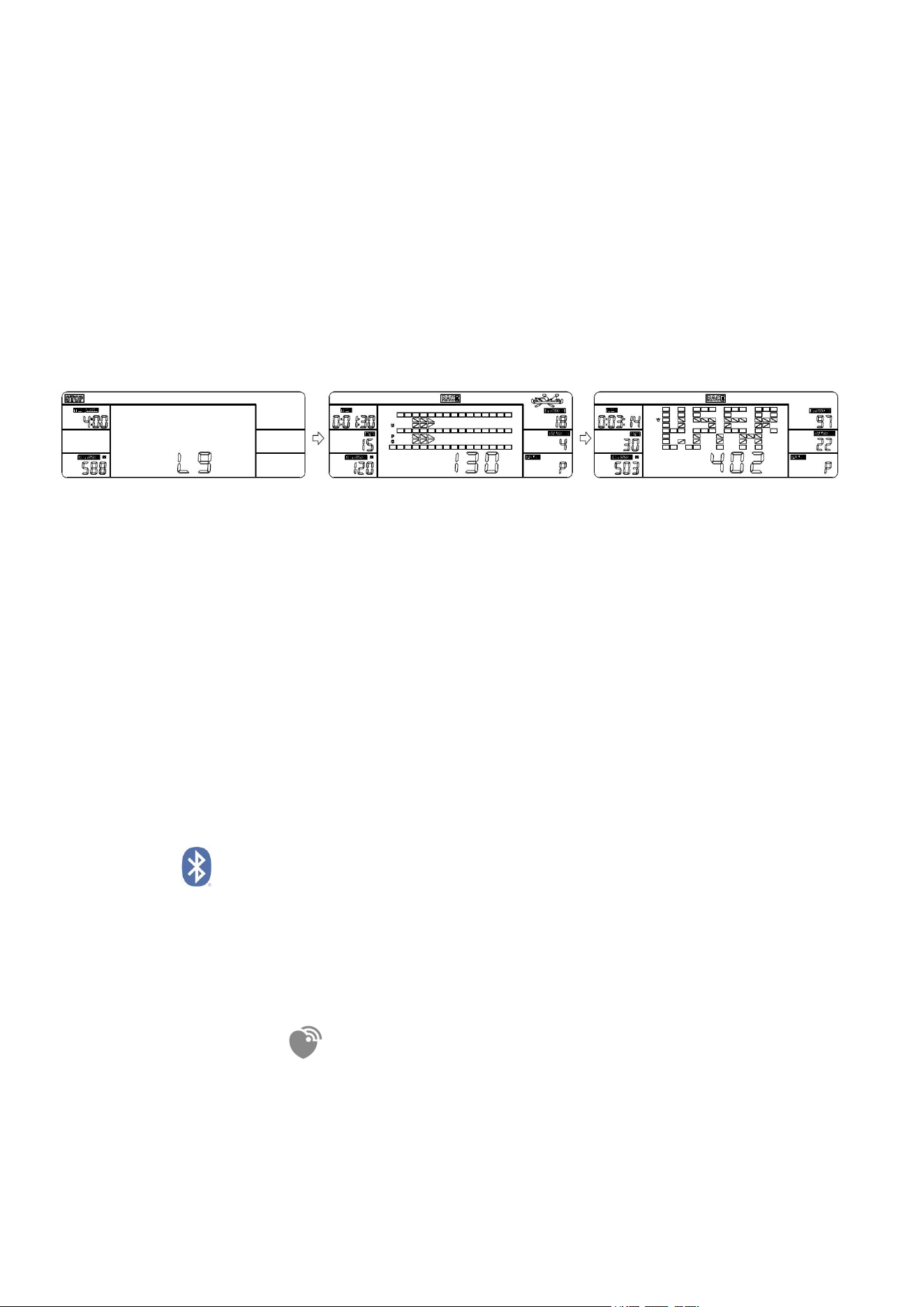
RACE
Race mode. User-defined PC difficulty (L1-L15), you can choose the
distance to race: 500-10000 meters.
11
KEY FUNCTION
UP
1. Select exercise mode upwards.
2. Increase the value during setting.
DOWN
1. Select exercise mode downwards.
2. Decrease the value during setting.
MODE
1. During exercise, switch the display: TIME or TIME/500, STROKES
or TOTAL STROKES, CALORIES or WATT.
2. In PROGRAM mode or RACE mode, select and fix a function to set.
RESET
1. Return to the initial interface in stop state.
2. Reset the setting values to 0 when Bluetooth is not connected.
3. Press and hold the key for 2 seconds to clear all the function values
except TOTAL STROKES when Bluetooth is not connected.
4. Press and hold the key for 6 seconds to disconnect from both the
SunnyFit APP and the heart rate monitor; then, the meter will enter
sleep mode.
START/STOP
1. Enter the exercise mode.
2. Start or stop exercise.
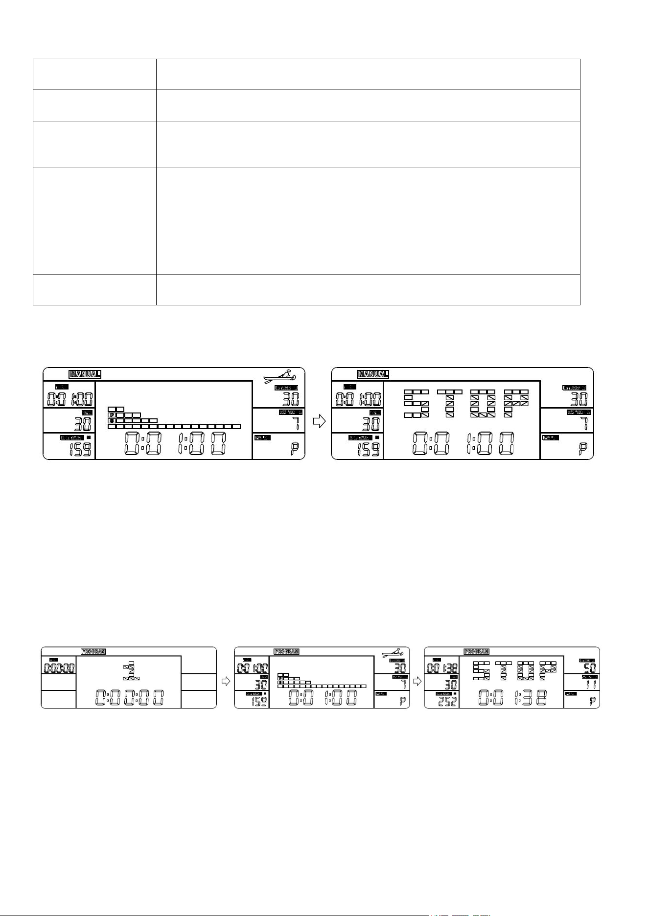
MANUAL MODE
Press UP or Down key to select and lock onto “MANUAL”.
Press START/STOP key to start exercise.
Press UP or DOWN key to select a particular function value to display in main window.
Press MODE key to select and fix a function to display: TIME, STROKES, CALORIES or
TIME/500, TOTAL STROKES, WATT.
When in stop state, press START/STOP key to restart; when in exercise state; press the
START/STOP key to stop.
Press RESET key to return to the initial interface in stop state.
PROGRAM MODE
Press UP or Down key to select and lock onto “PROGRAM”.
Press START/STOP key to set the mode.
Press MODE key to select a function to set: TIME→DISTANCE→STROKES
→CALORIES→PULSE.
Press UP or DOWN keys to increase or decrease the setting value. Press RESET key to reset
the setting value to 0.
Press START/STOP key to start exercise.
Press UP or DOWN key to select a particular function value to display in main window.
12
Press MODE key to select and fix a function to display: TIME or TIME/500, STROKES or
TOTAL STROKES, CALORIES or WATT.
If any function is set, at exercise state, this function is displayed as a countdown (except
PULSE). When the countdown reaches 0, the exercise will automatically stop with a "DI DI"
sound prompt.
If PULSE value is set, at exercise state, when your pulse value surpasses the target value, the
exercise will automatically stop with a "DI DI" sound prompt.
When in stop state, press START/STOP key to restart; when in exercise state; press the ST./SP.
key to stop.
Press RESET key to return to the initial interface in stop state.
NOTE: If more than one function value is set, only the last function value is valid.
RACE MODE
Press UP or Down key to select and lock onto “RACE”.
Press ST./SP. key to set the mode.
Press MODE key to select the function to set: TIME/500 or DISTANCE.
Press UP or DOWN key to increase or decrease the setting value.
PC level of difficulty is L1-L15. At higher difficulty, the PC will finish the race faster.
Press ST./SP. key to start exercise.
The one who finishes the race first is the winner.
When in stop state, press START/STOP key to restart; when in exercise state; press the
START/STOP key to stop.
Press RESET key to return to the initial interface in stop state.
■SLEEP MODE
The system turns off automatically and disconnects the heart rate monitor if the sensor has no
signal input, or no key are pressed for approximately 4 minutes when Bluetooth is not
connected.
The system turns on when any key is pressed or there is a signal input.
BLUETOOTH :
1
. The Bluetooth icon will flash when the meter is on or wakes from sleep mode. If no Bluetooth
connection is established within 3 minutes, the Bluetooth icon will turn off.
2. The Bluetooth icon will stay on when it is connected.
WIRELESS HEART RATE :
1. The wireless heart rate icon will flash when the meter is on. If the heart rate monitor is not
connected within 1 minute, the wireless heart rate icon will turn off.
2. After exercise resumes, the wireless heart rate icon will flash. If the heart rate monitor is not
connected within 1 minute, the wireless heart rate icon will turn off.
3. When the meter wakes from sleep mode, the wireless heart rate icon will flash. If the heart rate
monitor is not connected within 1 minute, the wireless heart rate icon will turn off.

13
4. The wireless heart rate icon will flash when the MODE key is pressed. If the heart rate monitor is
not connected within 1 minute, the wireless heart rate icon will turn off.
5. The wireless heart rate icon will stay on when the heart rate monitor is connected.
NOTE: The heart rate monitor is not included. Wireless heart rate function works with SunnyFit
Heart Rate Monitor HR200. HR200 can only connect to the meter when the wireless heart rate icon
is flashing.
BATTERY
This meter uses 2 AA batteries, which are included. Changing the batteries will reset all values. If
there is a problem with the display, try to change the batteries first. When changing the batteries,
change both at the same time. Do not mix battery types. Do not mix old and new batteries. Dispose
of old batteries according to your regional guidelines.
TECHNICAL DATA
Connectivity: Bluetooth LE
Frequency Range: 2400~2483.5 Mhz
Transmitting Power: 0 dBm
APP CONNECTION:
Connect Smart Equipment to SunnyFit App:
1. Scan to download SunnyFit from the app store:
2. Ensure that the Bluetooth function is turned on from your mobile device.
3. If this is your first time using the SunnyFit app, follow the in-app instructions to register for your
free SunnyFit account and log in.
4. Begin any workout activity that matches your smart equipment, then follow the onscreen
prompts to search for and connect to your smart equipment.
5. When connected, your stats and records will be displayed at the end of your course/session
and recorded in your account profile!
Troubleshooting:
If you are having trouble connecting your smart equipment, visit www.sunnyfit.com/guide or
scan the QR code below:
If you require additional support, please contact support@sunnyfit.com.
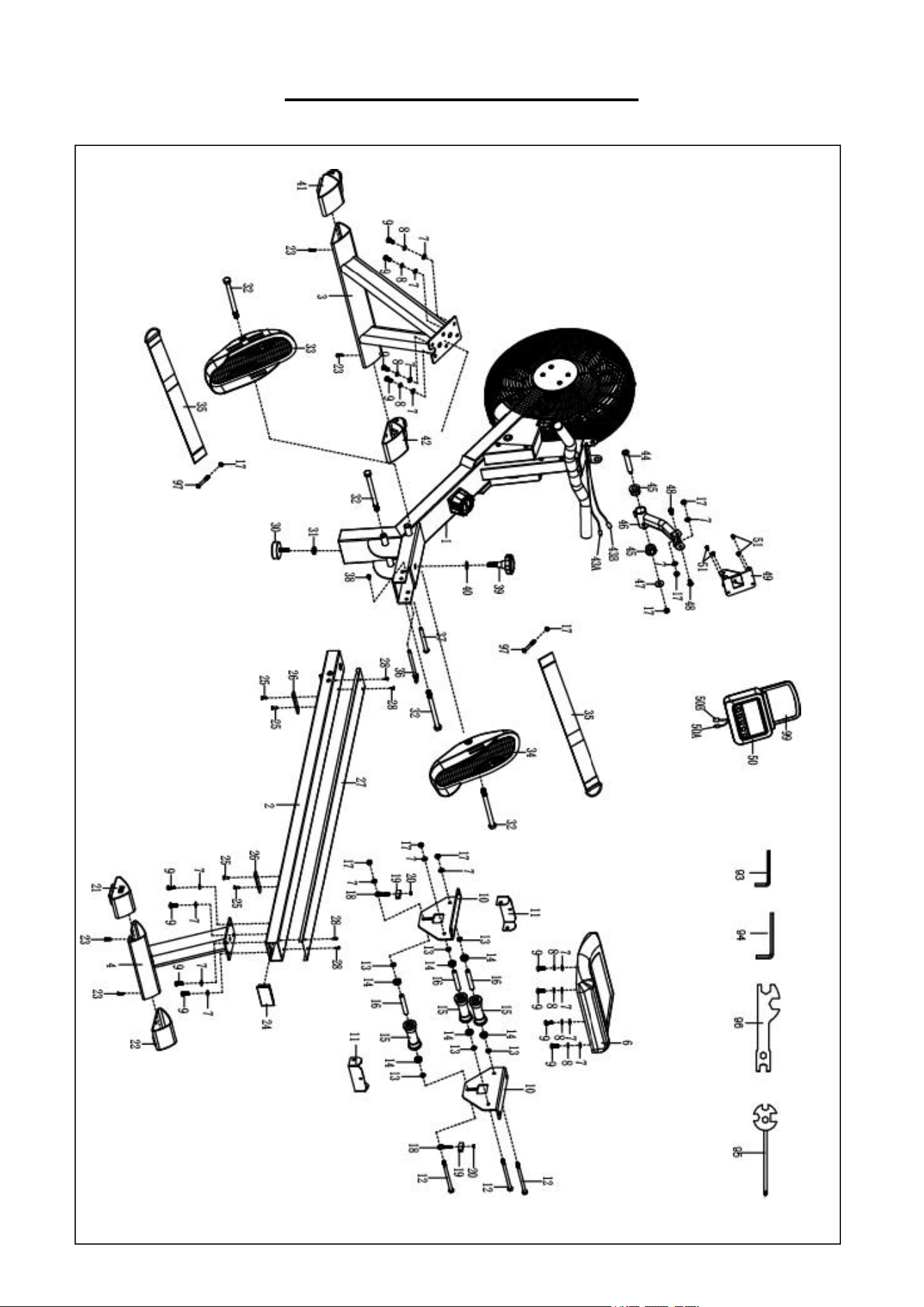
14
EXPLODED DIAGRAM 1
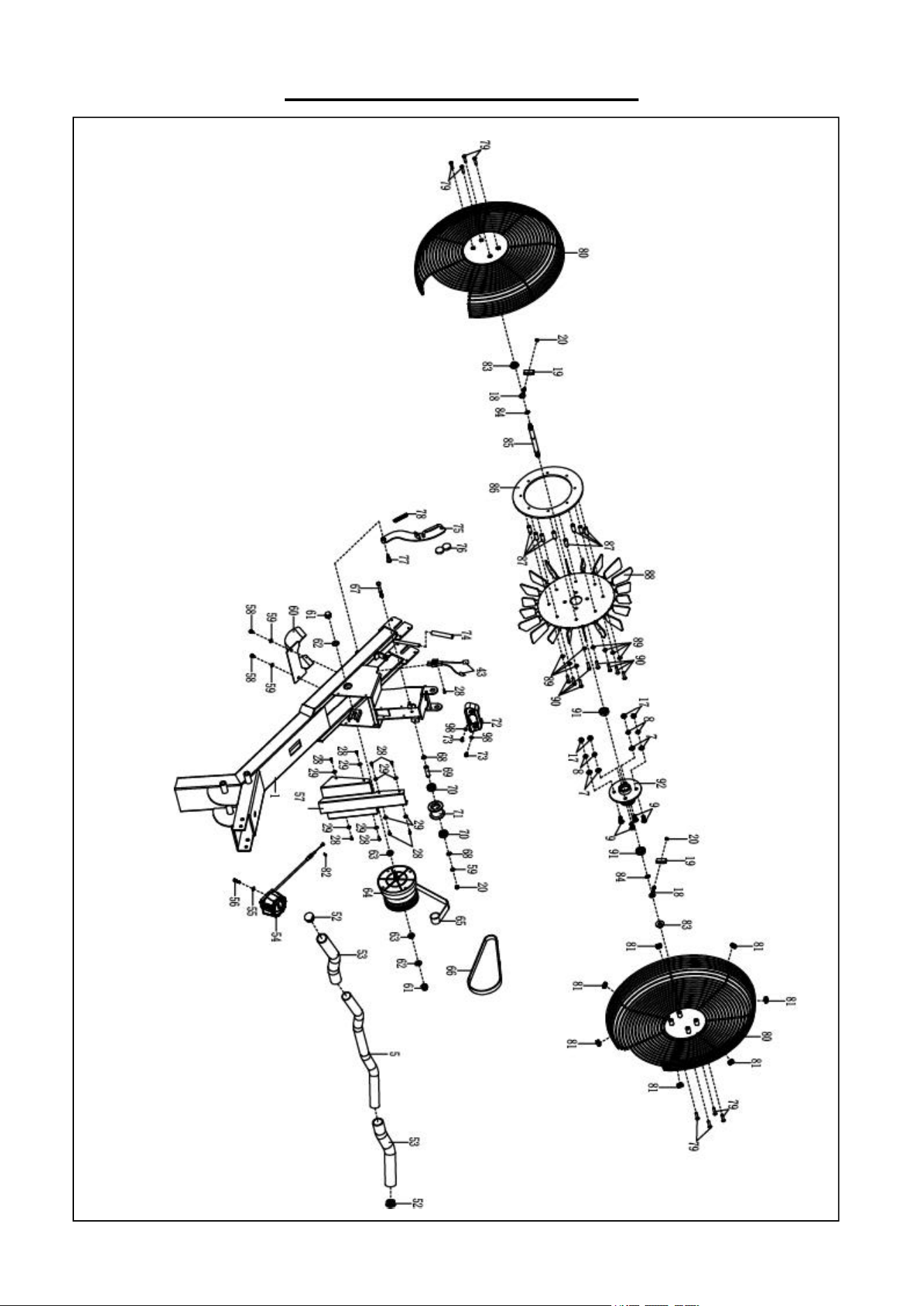
15
EXPLODED DIAGRAM 2
16
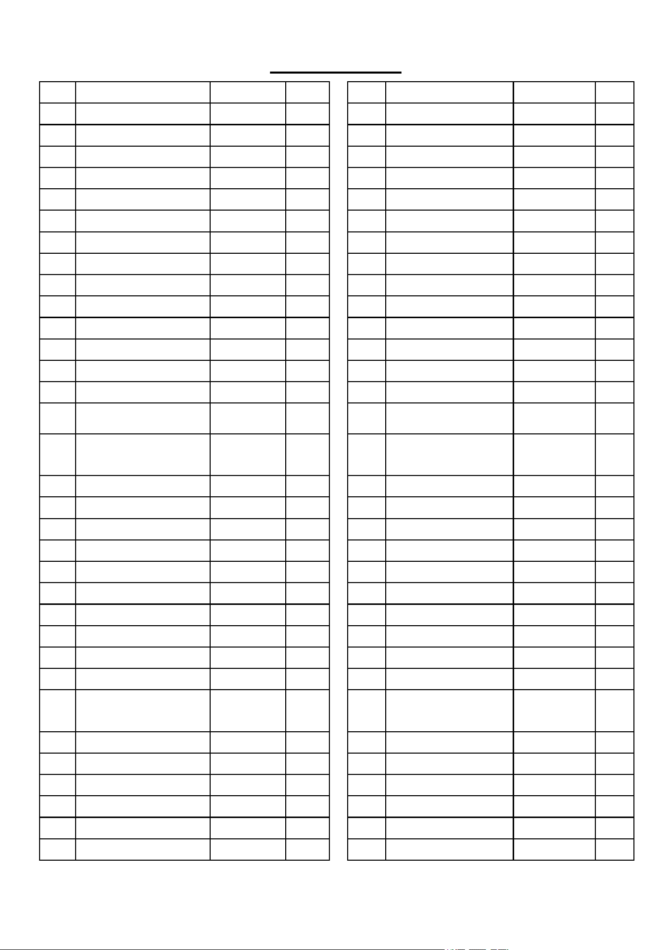
PARTS LIST
No.
Description
Spec.
Qty.
No.
Description
Spec.
Qty.
1
Main Frame
1
34
Right Pedal
1
2
Sliding Rail
1
35
Pedal Strap
2
3
Front Stabilizer
1
36
Pull Pin
Ф8.0*106
1
4
Rear Stabilizer
1
37
Bolt
Ф10*95
1
5
Handlebar
Φ28*1.5
1
38
Bolt
M6*15
1
6
Seat
1
39
Knob
M12*30
1
7
Washer
Ф8*Ф16*1.5
21
40
Washer
Ф24*Ф12.5*2
1
8
Spring Washer
Ф8
12
41
Left End Cap
1
9
Bolt
M8*20
16
42
Right End Cap
1
10
Seat Supporting Board
2
43
Sensor Wire
L=500MM
1
11
U Shape Bracket
2
43A
Sensor Wire A
1
12
Bolt
M8*125
3
43B
Sensor Wire B
1
13
Spacer
Ф15*Ф8*4
6
44
Bolt
M8*S6
1
14
Bearing
608
6
45
Axle Sleeve
2
15
Wheel
Ф39*92
3
46
Meter Supporting Tube
1
16
Casing Pipe for Idler
Wheel
Ф12*Ф9*78
3
47
Big Washer
Ф8*Ф25*2.0
1
17
Nut
M8
12
48
Bolt
M8*15
2
18
Adjusting Screw
M6*36
4
49
Meter Holder
1
19
U Shape Baffle
31*30*1.0
4
50
Meter
1
20
Nut
M6 S10
5
50A
Meter Wire A
1
21
Left End Cap
1
50B
Meter Wire B
1
22
Right End Cap
1
51
Screw
M5*10
4
23
Screw
ST4.2*20
4
52
Round End Cap
Ф28*1.5
2
24
Square Plug
1
53
Foam Grip
Ф27*Ф33*244
2
25
Screw
M6*15
4
54
Tension Control Knob
1
26
Limit Mat
80*18*5
2
55
Washer
Ф5
1
27
U Shape Stainless Steel
Sheet
1
56
Bolt
M5*45
1
28
Screw
ST4.2*15
13
57
Cover Plate
1
29
Washer
Ф4*Ф11*1.0
8
58
Screw
M6*15
2
30
Foot Pad
M10*30
1
59
Washer
Ф6*Ф12*1.0
3
31
Nut
M10
1
60
Back Plate
1
32
Bolt
M12*155
4
61
Nut
M10*1.0
2
33
Left Pedal
1
62
Washer
Ф10*Ф20*2.0
2
17
No.
Description
Spec.
Qty
No.
Description
Spec.
Qty
63
Nut
M10*1
2
82
Nut
M4
1
64
Volute Spring Complete
Set
1
83
Nut
M10*1.0*9
2
65
Mesh Belt
1
84
Shaft Snap Ring
Ф12*1.0
2
66
Belt
320PJ
1
85
Inertial Wheel Shaft
1
67
Bolt
M6*55
1
86
Aluminium Plate
1
68
Shaft Snap Ring
Ф10*1.0
2
87
Stainless Steel
Sleeve
8
69
Belt Pulley Shaft
Ф10*40
1
88
Fan Blade
1
70
Bearing
6000
2
89
Washer
Ф6*Ф14*1.5
8
71
Mesh Belt Pulley
Φ45*35
1
90
Bolt
M6*35
8
72
Handle Guide
1
91
Bearing
6001
2
73
Bolt
M5*10
2
92
Fan Wheel Shaft
1
74
Rubber Tubing
1
93
Wrench
S5
1
75
Magnetic Plate
1
94
Wrench
S6
1
76
Magnet
2
95
Spanner
S10, 13, 14,
15
1
77
Bolt
M6*10
1
96
Spanner
S10, 13, 17,
19
1
78
Spring
Ф8*Ф1*58
1
97
Bolt
M8*60
2
79
Screw
M6*25
8
98
Washer
Ф5*Ф10*1.0
2
80
Cover
2
99
Tablet Holder
1
81
Buckle
M4*10
7