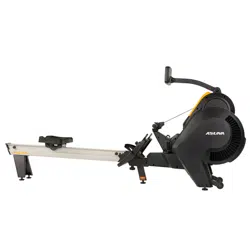
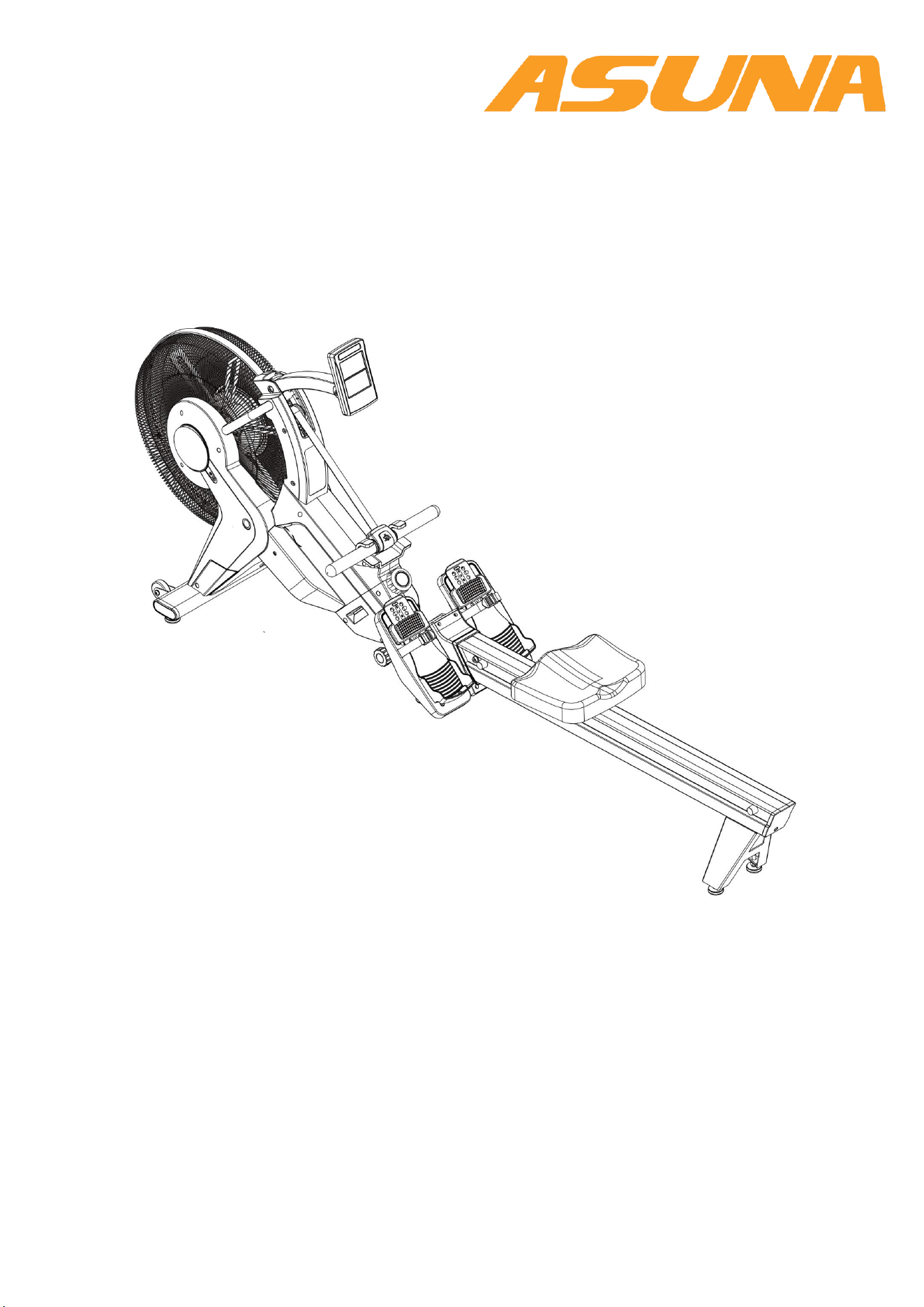
8580 VENTUS AIR MAGNETIC ROWER
USER MANUAL
IMPORTANT: Read all instructions carefully before using this product. Retain
owner’s manual for future reference. For customer service, please contact:
support@sunnyhealthfitness.com

2
IMPORTANT SAFETY INFORMATION
IMPORTANT SAFETY INFORMATION
We thank you for choosing our product. To ensure your safety and health, please use this equipment
correctly. It is important to read this entire manual before assembling and using the equipment. Safe
and effective use can only be achieved if the equipment is assembled, maintained and used properly.
It is your responsibility to ensure that all users of the equipment are informed of all warnings and
precautions.
1. Before starting any exercise program you should consult your physician to determine if you have
any medical or physical conditions that could put your health and safety at risk, or prevent you from
using the equipment properly. Your physician’s advice is essential if you are taking medication that
affects your heart rate, blood pressure or cholesterol level.
2. Be aware of your body’s signals. Incorrect or excessive exercise can damage your health. Stop
exercising if you experience any of the following symptoms: pain, tightness in your chest, irregular
heartbeat, shortness of breath, lightheadedness, dizziness or feelings of nausea. If you do
experience any of these conditions, you should consult your physician before continuing with your
exercise program.
3. Keep children and pets away from the equipment. The equipment is designed for adult use only.
4. Use the equipment on a solid, flat level surface with a protective cover for your floor or carpet. To
ensure safety, the equipment should have at least 2 feet (60cm) of free space all around it.
5. Ensure that all nuts and bolts are securely tightened before using the equipment. The safety of the
equipment can only be maintained if it is regularly examined for damage and/or wear and tear.
6. Always use the equipment as indicated. If you find any defective components while assembling or
checking the equipment, or if you hear any unusual noises coming from the equipment during
exercise, discontinue use of the equipment immediately and do not use until the problem has been
rectified.
7. Wear suitable clothing while using the equipment. Avoid wearing loose clothing that may become
entangled in the equipment. Do not use without shoes, or with loose shoes.
8. Do not place fingers or objects into moving parts of the exercise equipment.
9. The maximum weight capacity of this unit is 330 pounds (150 kgs).
10. The equipment is not suitable for therapeutic use.
11. Please take proper precautions when lifting and moving the equipment. Always use proper lifting
technique and seek assistance if necessary.
12. For all adjustable parts be aware of the maximum position to which they can be adjusted.
13. Be aware of non-fixed or moving parts while mounting or dismounting the bike.
14. We take no responsibility for personal injury or damage sustained by or through the use of this
exercise bike.
3
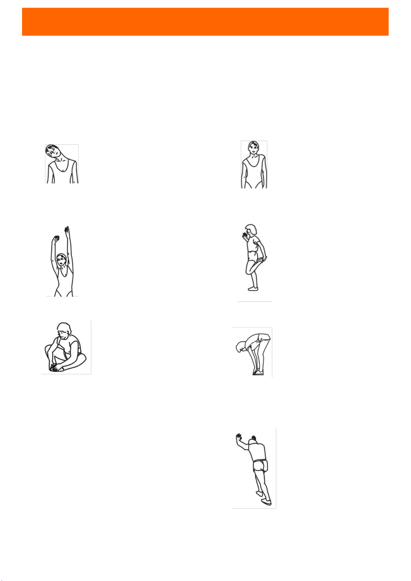
WARM UP & COOL DOWN
The warming up is an important part of your workout. It should begin every session to
prepare your body for more strenuous exercise by heating up and stretching out your
muscles. Cool down at the end of your workout, repeat these exercises to reduce soreness
in tired muscles. We suggest the following warm-up and cool-down exercises:
HEAD ROLLS
SHOULDER LIFTS
SIDE STRETCHES
QUADRICEPS STRETCH
INNER THIGH STRETCH
TOE TOUCHES
HAMSTRING STRETCHES
CALF/ACHILLES STRETCH
Rotate your head to the right for
one count, feeling the stretch up
the left side of your neck, then
rotate your head back for one
count, stretching your chin to the
ceiling and letting your mouth
open. Rotate your head to the left
for one count, then drop your
head to your chest for one count.
Lift your right shoulder toward
your ear for one count. Then lift
your left shoulder up for one
count as you lower your right
shoulder.
Open your arms to the side and lift
them until they are over your head.
Reach your right arm as far toward
the ceiling as you can for one
count. Repeat this action with your
left arm.
With one hand against a wall for
balance, reach behind you and
pull your right foot up. Bring your
heel as close to your buttocks as
possible. Hold for 15 counts and
repeat with left foot.
Sit with the soles of your feet
together and your knees
pointing outward. Pull your feet
as close to your groin as possible.
Gently push your knees toward
the floor. Hold for 15 counts.
Slowly bend forward from your
waist, letting your back and
shoulders relax as you stretch
toward your toes. Reach as far as
you can and hold for 15 counts.
Extend your right leg. Rest the
sole of your left foot against
your right inner thigh. Stretch
toward your toe as far as
possible. Hold for 15 counts.
Relax and then repeat with left
leg.
Lean against a wall with your left
leg in front of the right and your
arms forward. Keep your right leg
straight and the left foot on the
floor; then bend the left leg and
lean forward by moving your hips
toward the wall. Hold, then repeat
on the other side for 15 counts.
4
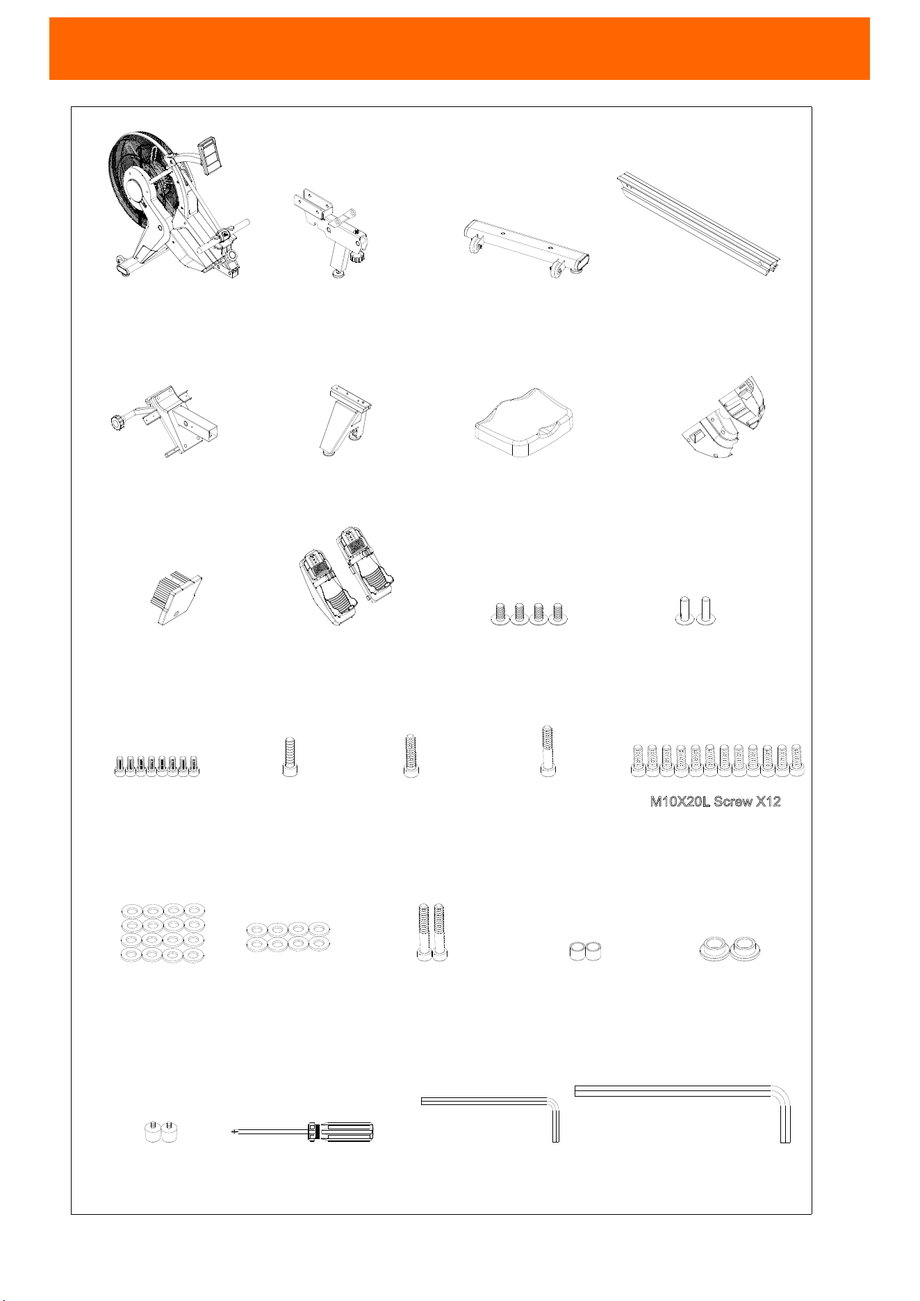
PARTS AND ASSEMBLY INSTRUCTIONS
M10X40L Screw X1
M10X50L Screw X1
M10X21X2.0T
Flat Washer X16
M5X113L Tool X1
M8X180L Tool X1
Rubber Pad X2
Frame
X1
Aluminum Rail X1
Rear Bracket For
Aluminum Rail X1
Rear Cover For
Aluminum Rail X1
Seat Assembly X1
RING X2SPACER RING X2
M5X12L Screw X4
M4X20L Screw X2
M6*10L Screw X8
M10X20L Screw X12
M6X16X1.5T
Flat Washer X8
Frame bracket set X1
Rail bracket set X1
Cover set for
main shrouds X1
Pedal set X1
Tool X1
Front stabilizer X1
M10X60L Screw X2
M6X20L Screw X1
NO. 1
NO. 120
NO. 81
NO. 110
NO. 93
NO. 74
NO. 86
NO. 114/115
NO. 75
NO. 103/104 NO. 58
NO. 57
NO. 50
NO. 51
NO. 53
NO. 54
NO. 52
NO. 56
NO. 55
NO. 62
NO. 61
NO. 60
NO. 59
M10X20L Screw X12
5
81
1
81
1
120
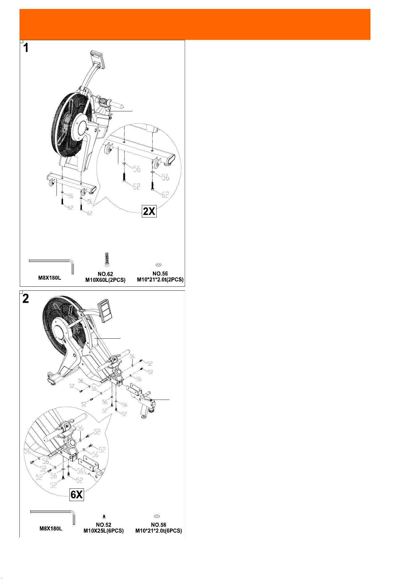
ASSEMBLY INSTRUCTIONS
STEP 1
Attach the Front Stabilizer (No. 81) to the Frame
(No. 1) using 2 Screws (No. 62) and 2 Washers.
STEP 2
Attach the Middle Fixed Set (No. 120) to the Frame
(No. 1) using 6 Screws (No. 52) and 6 Washers
(No. 56).
6
114
115
114
115
120
120
120
93
93
120
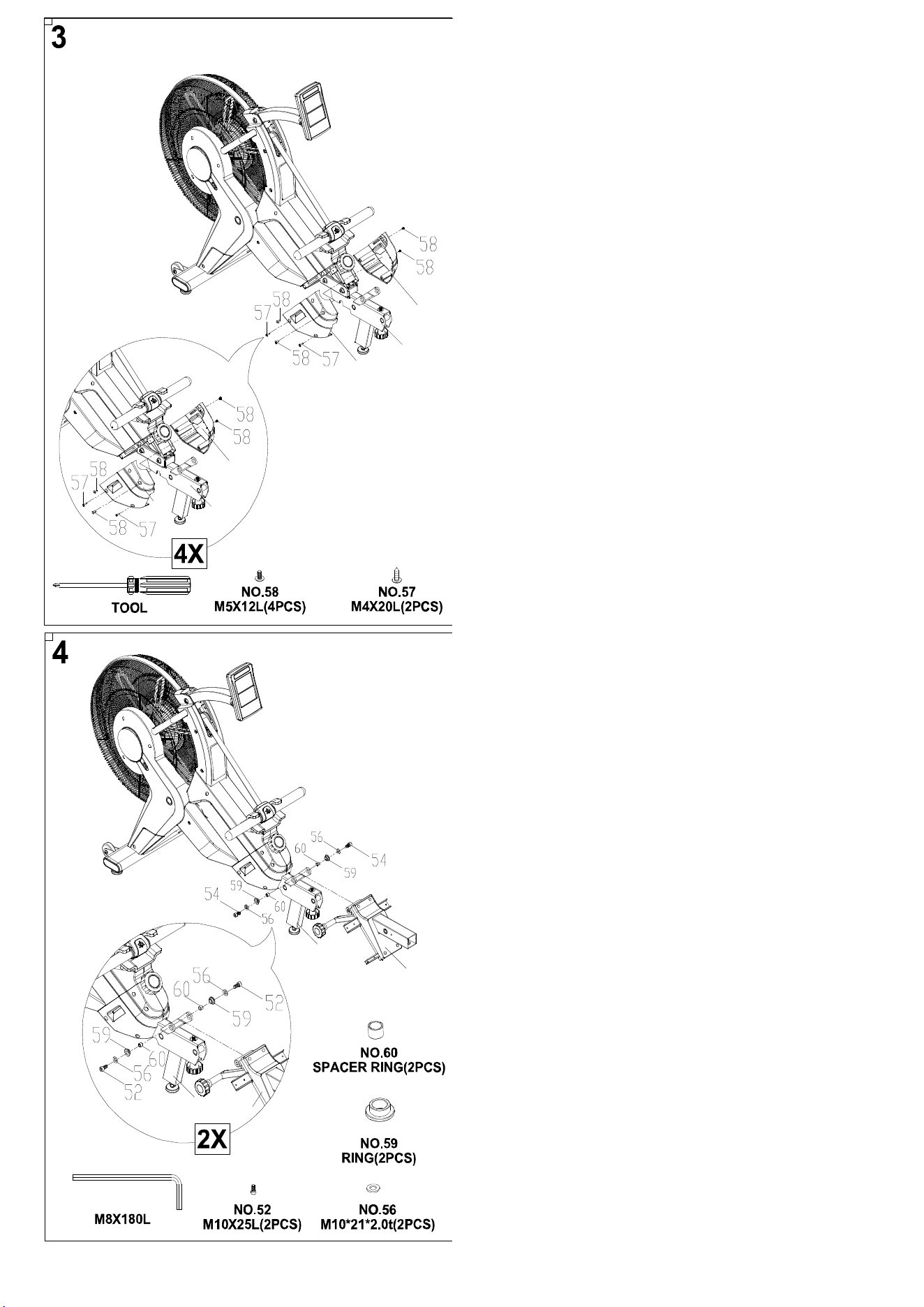
STEP 3
Attach the Left Case (No. 114) to the Middle Fixed
Set (No. 120) using 2 Screws (No. 58) and 2
Screws (No. 57).
Attach the Right Case (No. 115) to the Middle
Fixed Set (No. 120) using 2 Screws (No. 58).
STEP 4
Attach the Rail Bracket Set (No. 93) to the Middle
Fixed Set (No. 120) using 2 Screws (No. 52), 2
Washers (No. 56), 2 Rings (No. 59) and 2 Spacer
Rings (No. 60).
7
97
65
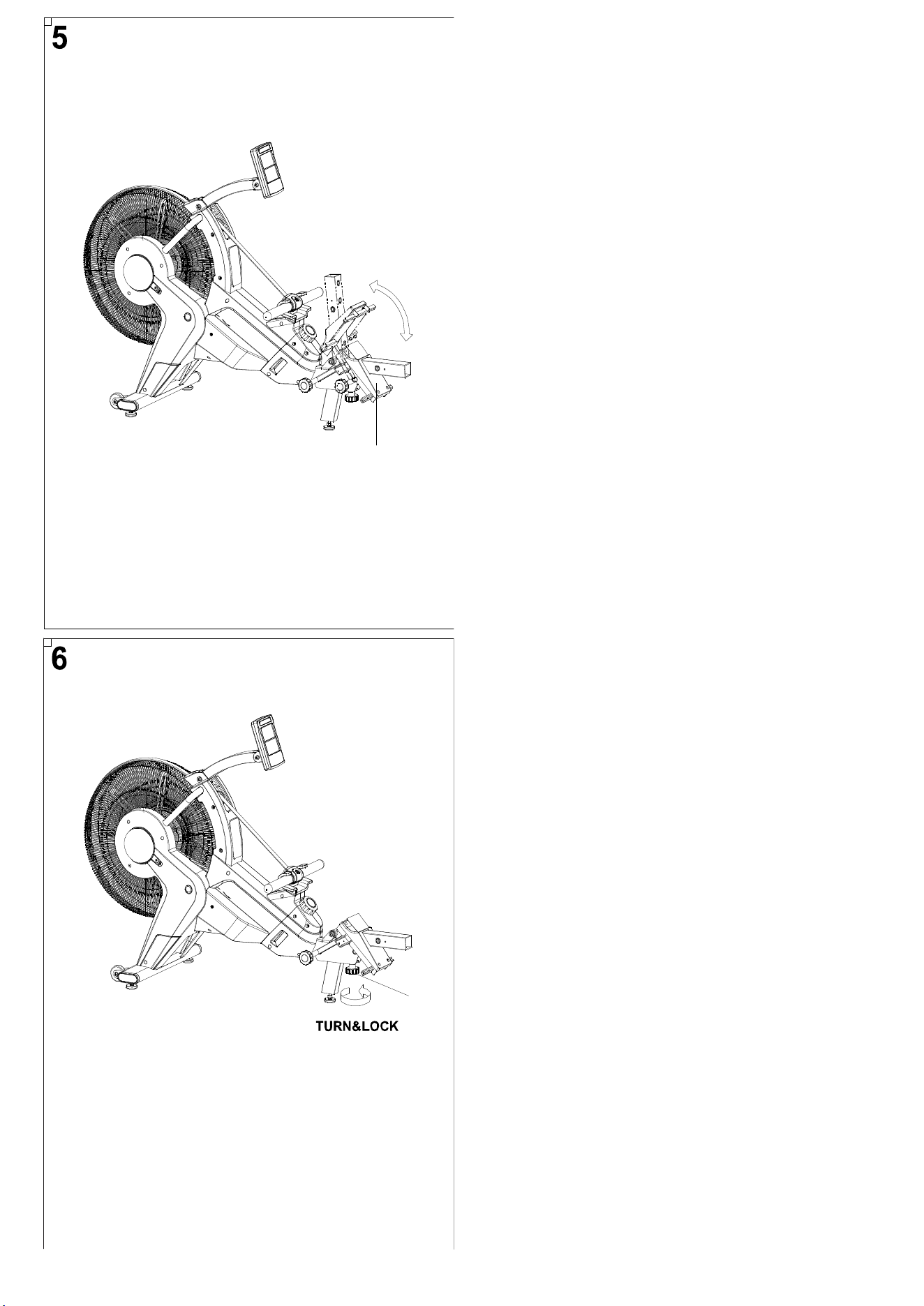
STEP 5
Check the Rail Bracket Cover (No. 97) can be
raised and lowered.
STEP 6
Turn Knob (No. 65) to tighten.
8
110
75
75
110
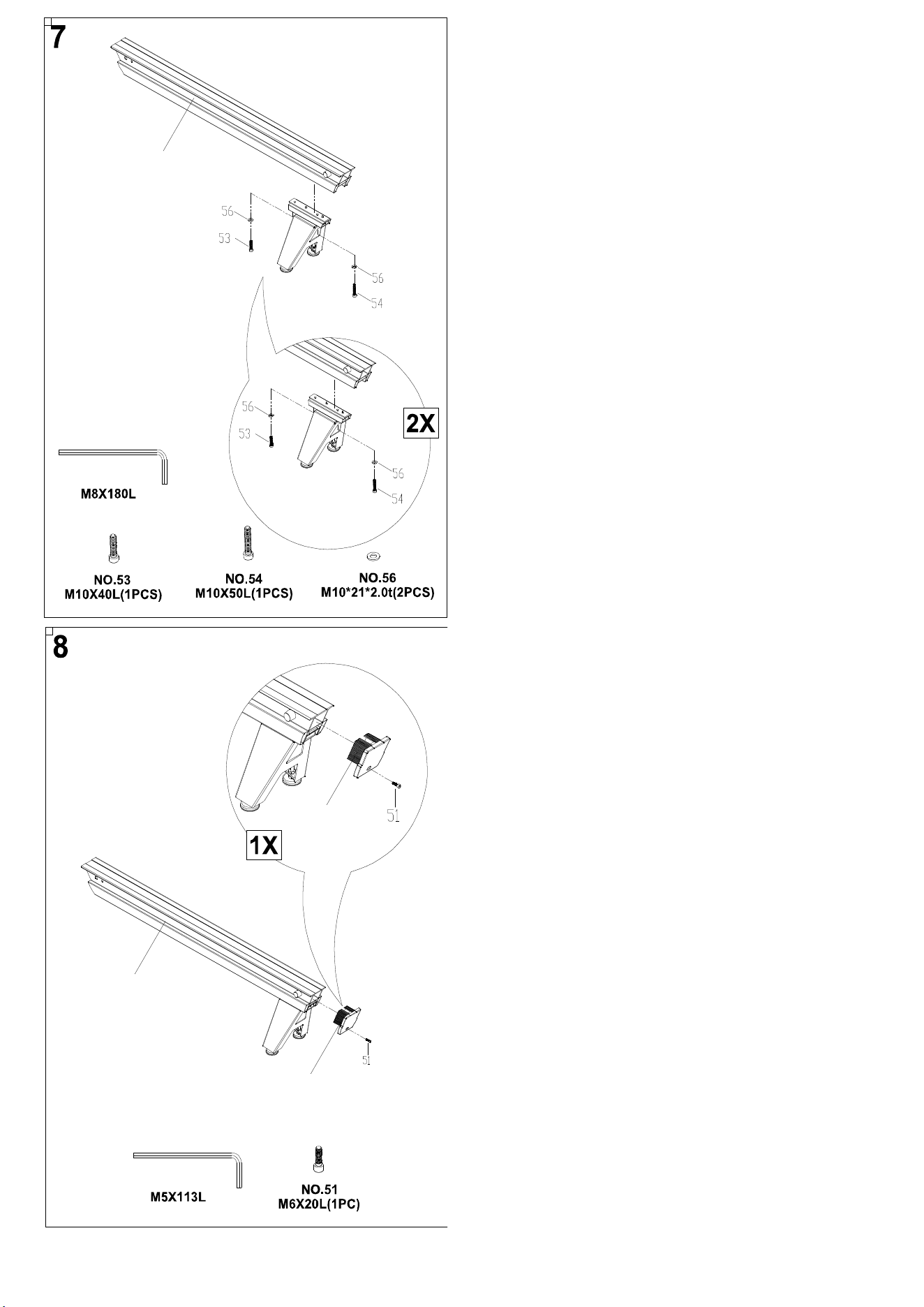
STEP 7
Attach the Rear Bracket to the Rail (No. 110) using
1 Screw (No. 53), 1 Screw (No. 54) and 2 Washers
(No. 56).
STEP 8
Attach the Rail Rear Cover (No. 75) to the Rail (No.
110) using Screw (No. 51).
9
110
110
111
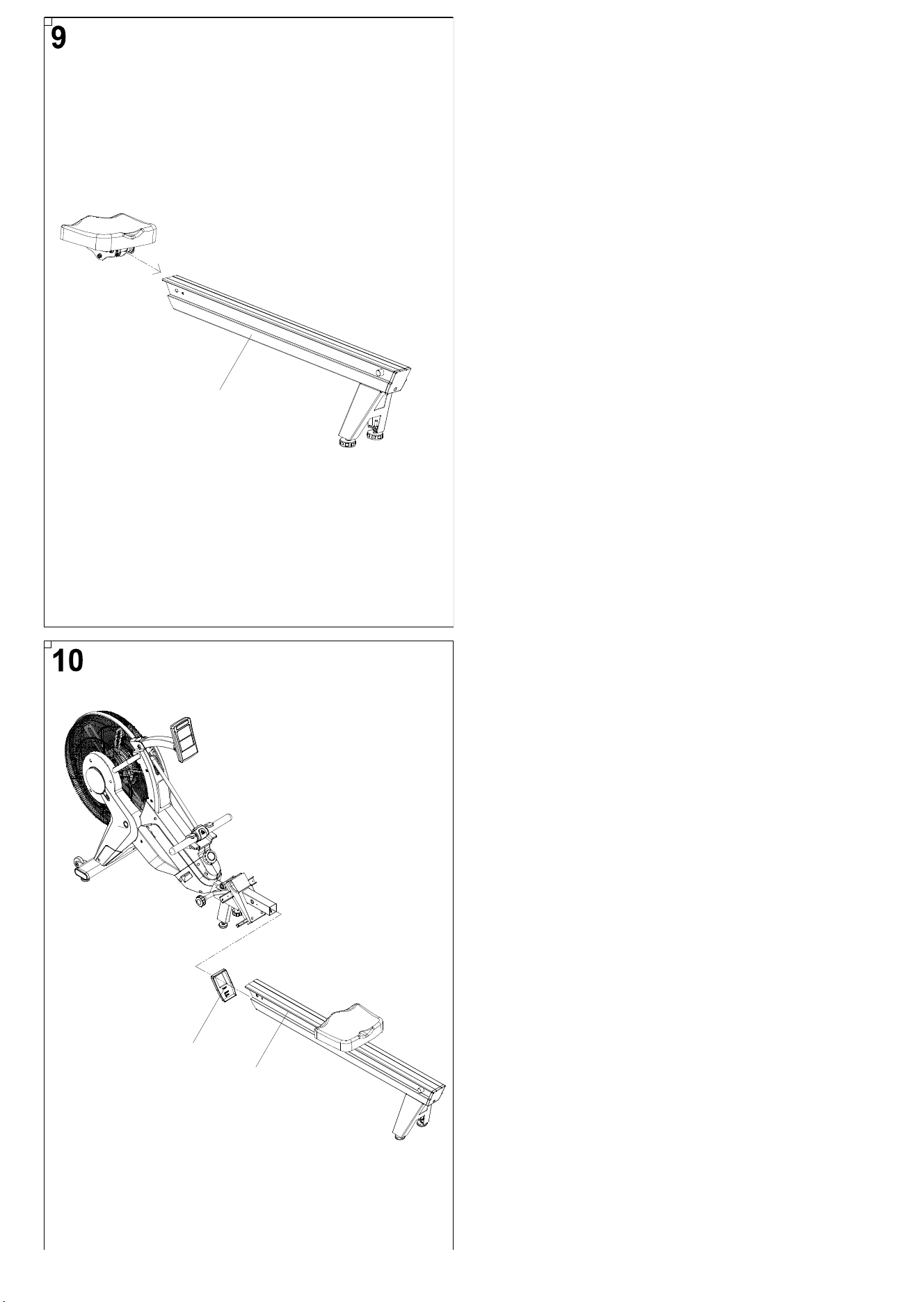
STEP 9
Slide the Seat Assembly onto the Rail (No. 110).
STEP 10
Attach the Rail Front Cover (No. 111) to the Rail
(No. 110).
10
110
93
110
110
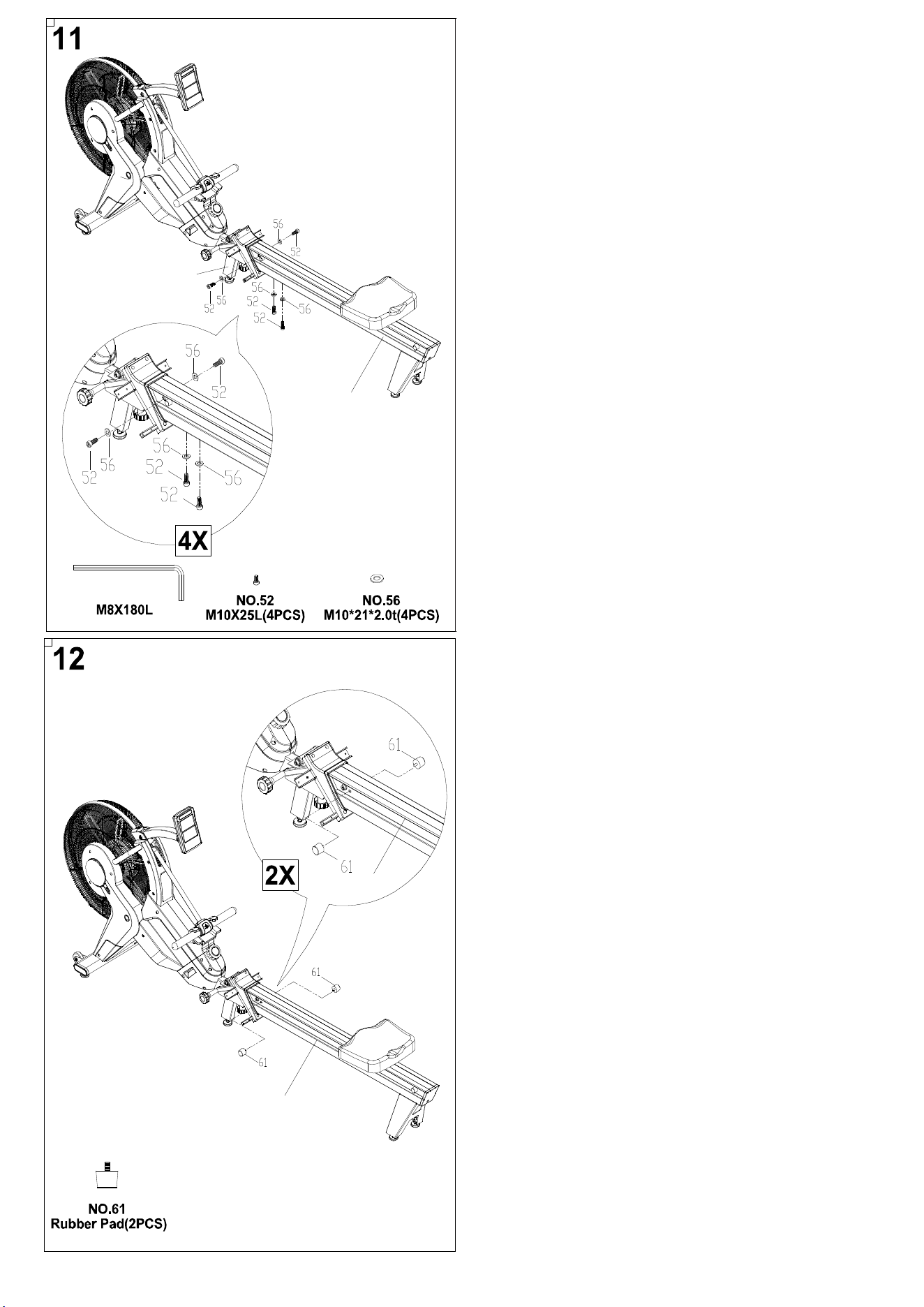
STEP 11
Attach the Rail (No. 110) to the Rail Bracket Set
(No. 93) using 4 Screws (No. 52) and 4 Washers
(No. 56).
STEP 12
Insert the 2 Rubber Pads (No. 61) into the Rail (No.
110).
11
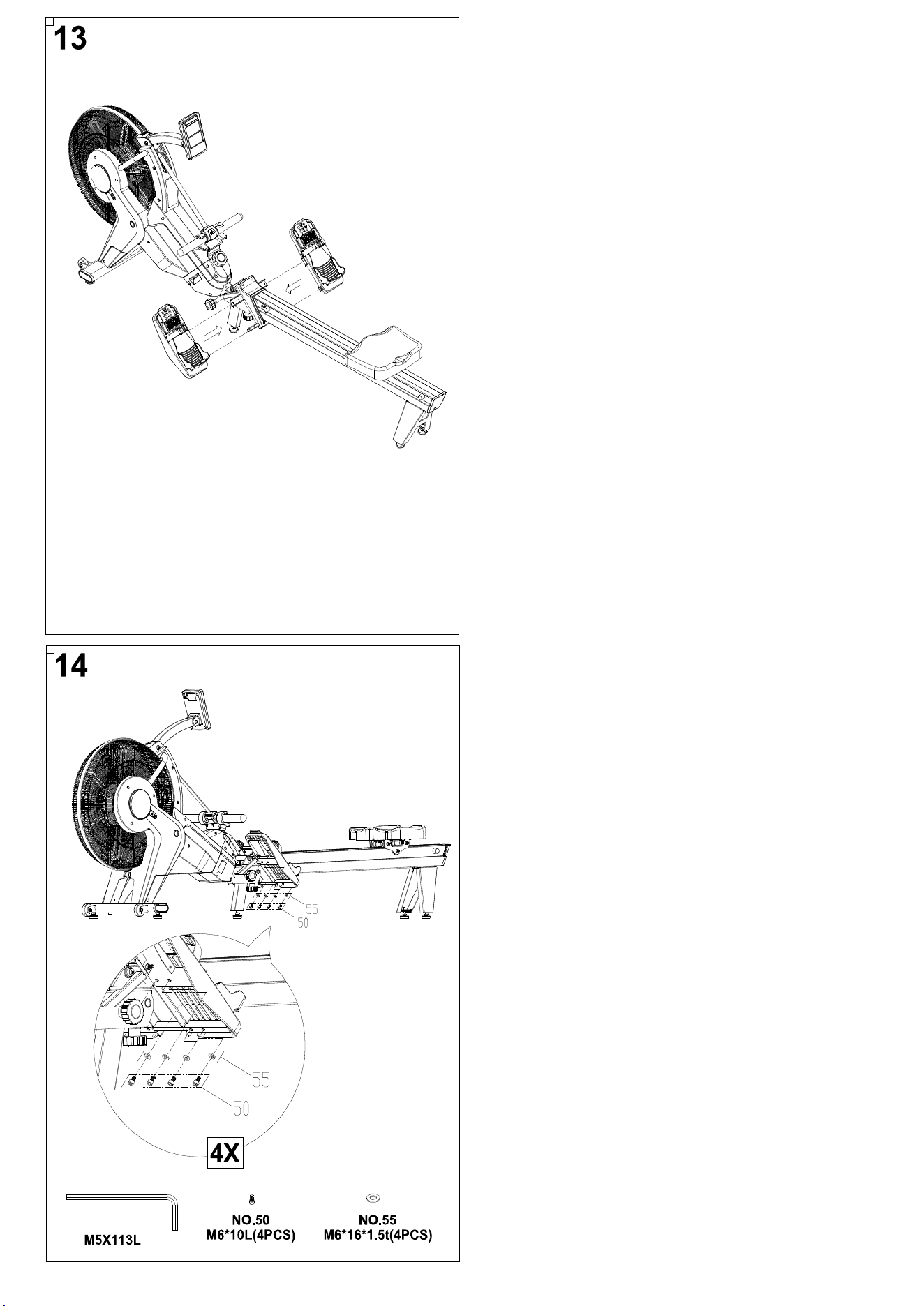
STEP 13
Slide the left and right pedals onto the rower.
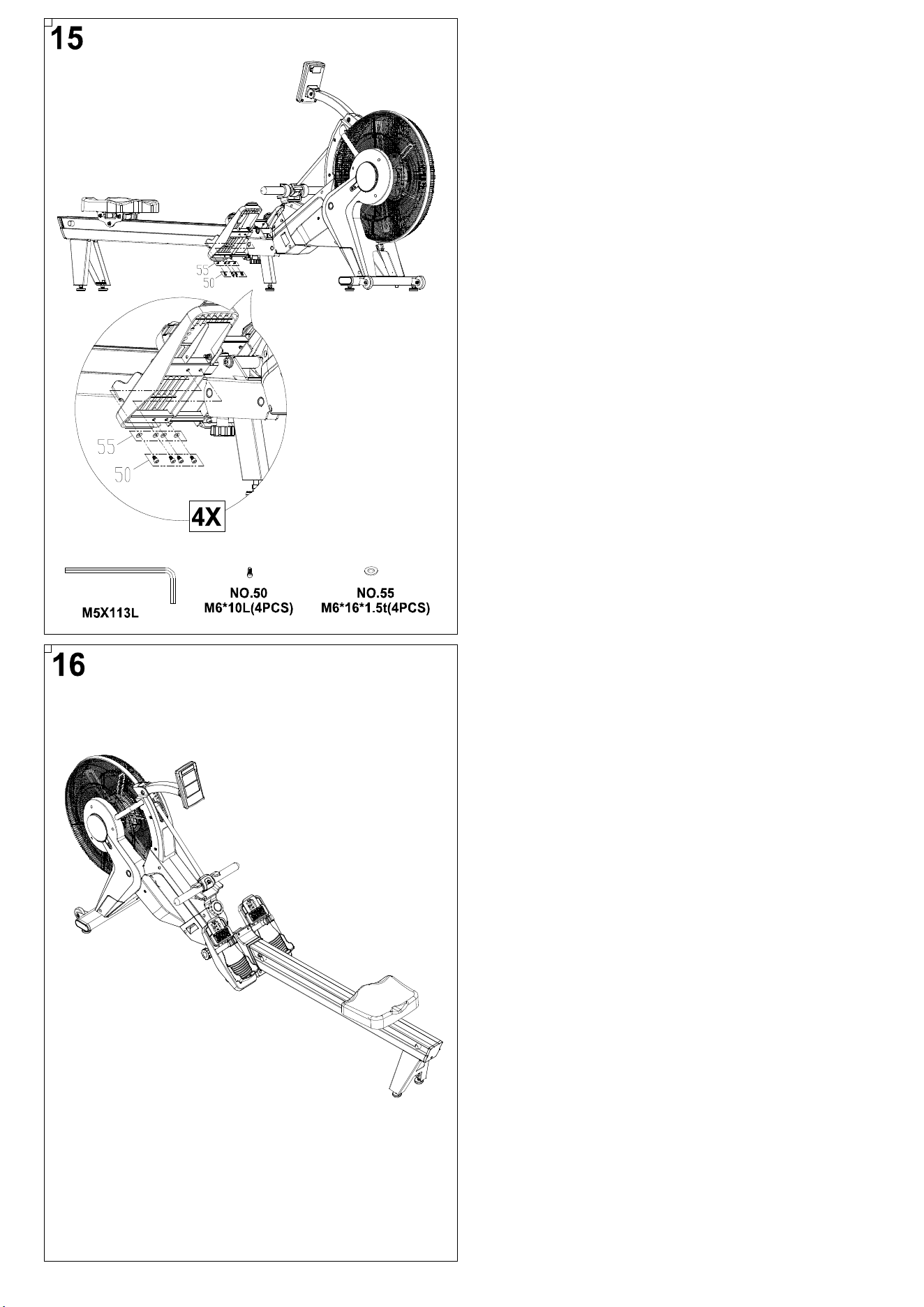
STEP 14
Attach the left pedal using 4 Screws (No. 50) and 4
Washers (No. 55).
12
STEP 16
Assembly is complete!
STEP 15
Attach the right pedal using 4 Screws (No. 50) and
4 Washers (No. 55).
13
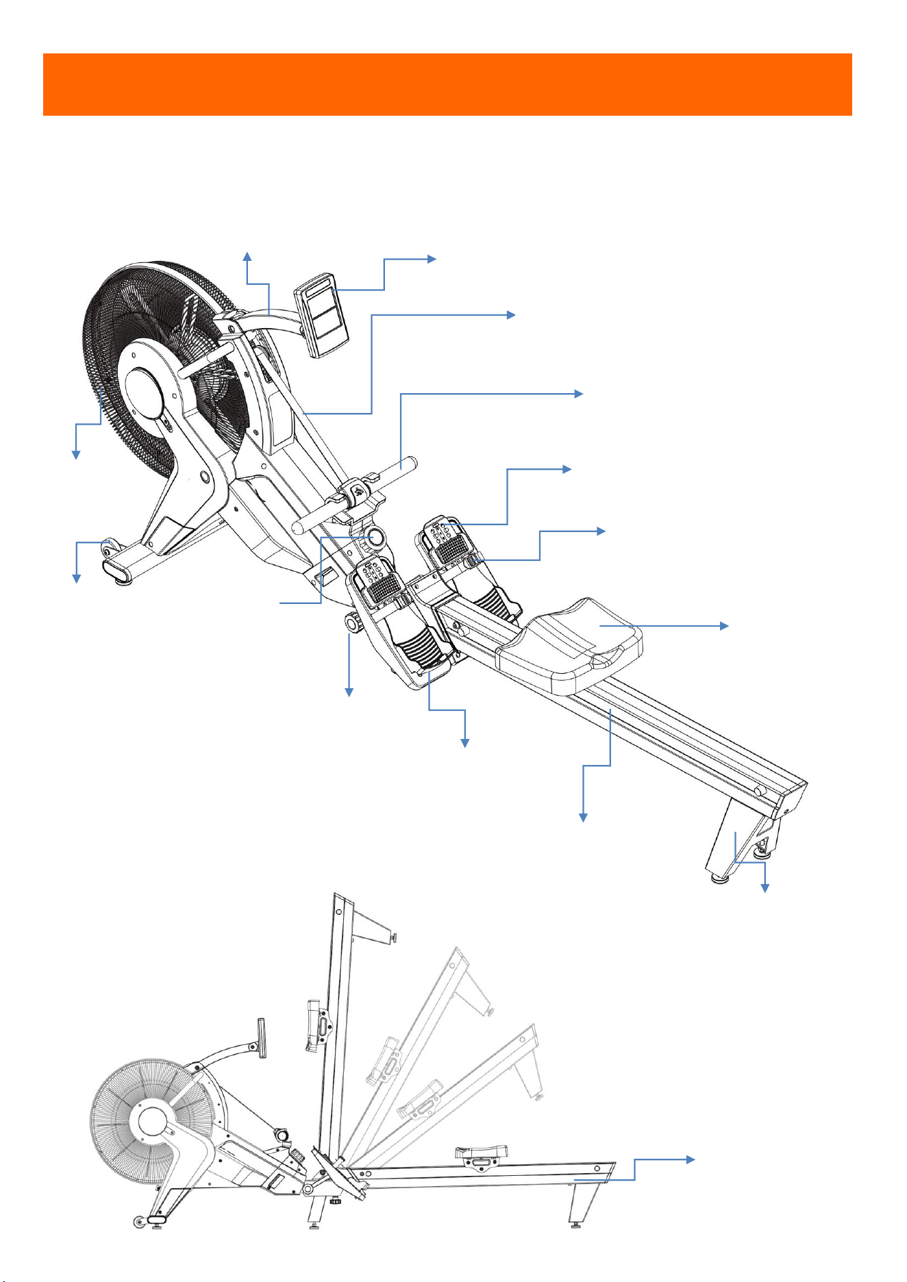
OVERVIEW
ADJUSTABLE CONSOLE ARM
CONSOLE
FOOT PEDAL
HANDLEBAR
FAN
ALUMINUM RAIL
SEAT
HEEL SUPPORTER
REAR BRACKET
FOLDING
THE
ROWER
MOVING
WHEEL
FOLDING
BOLT
PEDAL BELT
SPECIAL ROPE
TENSION
KNOB
14
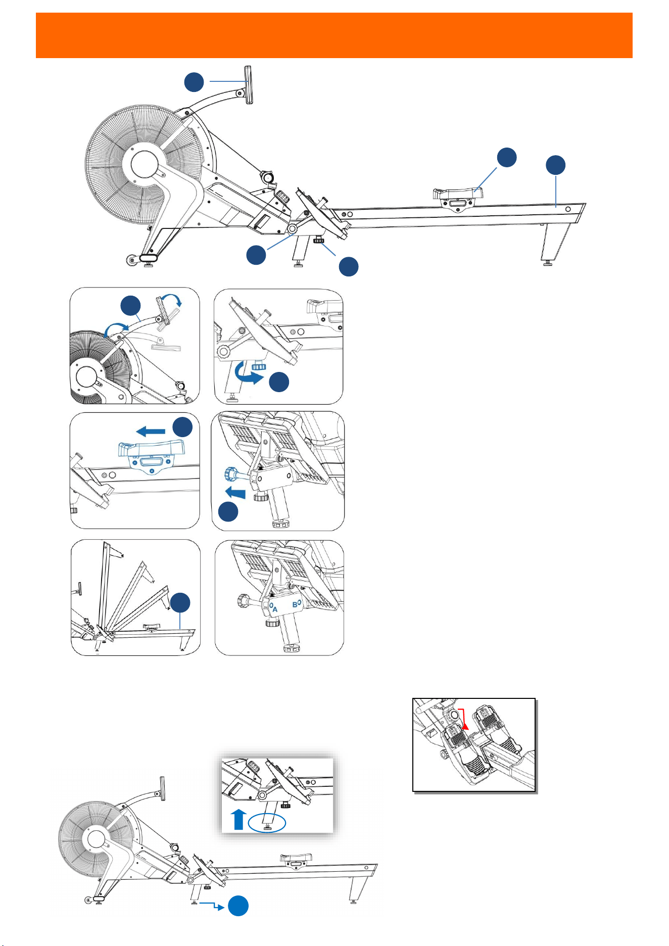
FOLDING INSTRUCTION
CAUTION
!
1.
Before and after exercise, make sure
knob is locked completely at Position
A or B.(
When lay down the rail flatly,
pull X
point up, and then the knob will
be well-locked)
2.
When you use machine, lay rail (H) flat
first. Then, adjust the feet (C) up for
3mm to prevent machine shaking
during exercise.
STEP 1
Press down console and adjustable arm
(G), and loosen the knob (1)
STEP 2
Then move the seat to the front rail.
STEP 3
Pull the bolt (3), and lift up rail (H)
When you use the machine, please
pull the bolt (3), put down rail (H),
and then lock the knob (1).
C
H
2
1
3
1
3
2
H
G
G
X
15
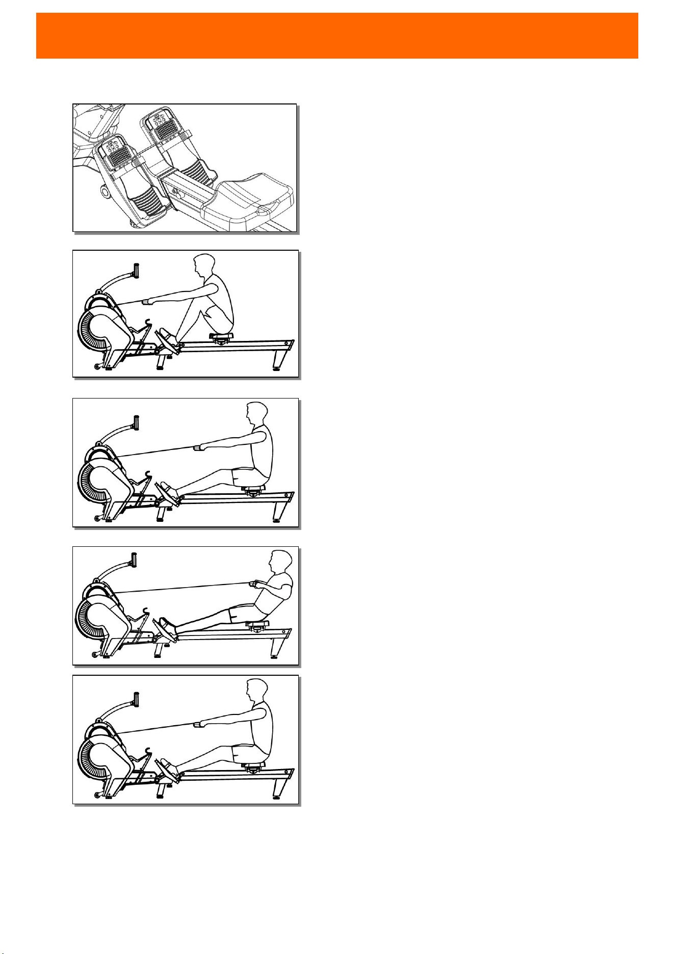
USING THE ROWING MACHINE
READY YOUR BODY
Sit down on the rowing seat and place your feet under
the adjustable straps. Pull the
straps tight to secure your
feet to the pedals. Adjust the pedals if needed. Lean your
body slightly forward with your back straight and extend
your arms to grab the handle.
STEP 1
Use your legs to push your body back. Keep your arms
straight and grip the handle firmly.
STEP 2
Begin to pull on the handle bar while bending your
elbows. As you pull with your arms, lean back slightly.
STEP 3
Pull the bar to the area between your navel and lower
chest. Keep your elbows close to your body.
RECOVER
To return to the starting position, extend your arms
first. Lean forward slightly while maintaining an
upright posture and tight core. Bend your knees to
slide the rowing seat back into the starting position.
CAUTION!
1. When returning to the starting position, make
sure to extend your arms first before bending
your knees.
2. Practice is encouraged since it might take some
time until your rowing form feels smooth.
3. During exercise, you should feel your hamstrings,
gluteus, dorsal, and biceps muscles being used.
4. When using rowing, please make sure the rope is
straight and not twisted.
16
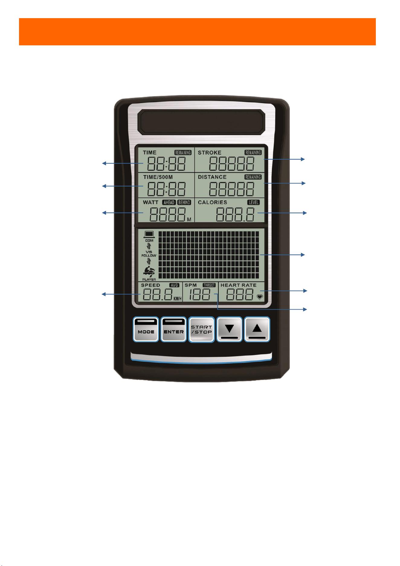
CONSOLE OVERVIEW
TIME
TIME FOR DISTANCE 500M
WATT
HEART RATE
CALORIES
EXERCISE DATA DISPLAY
STROKE RATE
SPEED
STROKE
DISTANCE
17
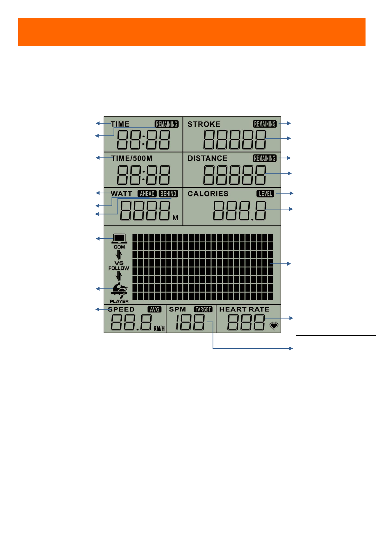
CONSOLE OVERVIEW
RACE MODE: COMPUTER
LEVEL
RACE MODE: YOU
TIME (MIN:SEC)
TIME / 500M (MIN:SEC)
WATT
HEART RATE (PULSE/MIN)
RACE MODE: INTENSITY
CALORIES (KCAL)
RESISTANCE LEVEL
EXERCISE DATA
SPM (STROKE/MIN)
RACE MODE: DISTANCE
AHEAD/BEHIND (M)
SPEED (KM/HR)
STROKE
DISTANCE
REMAINING
STROKE
REMAINING TIME
REMAINING
DISTANCE
18
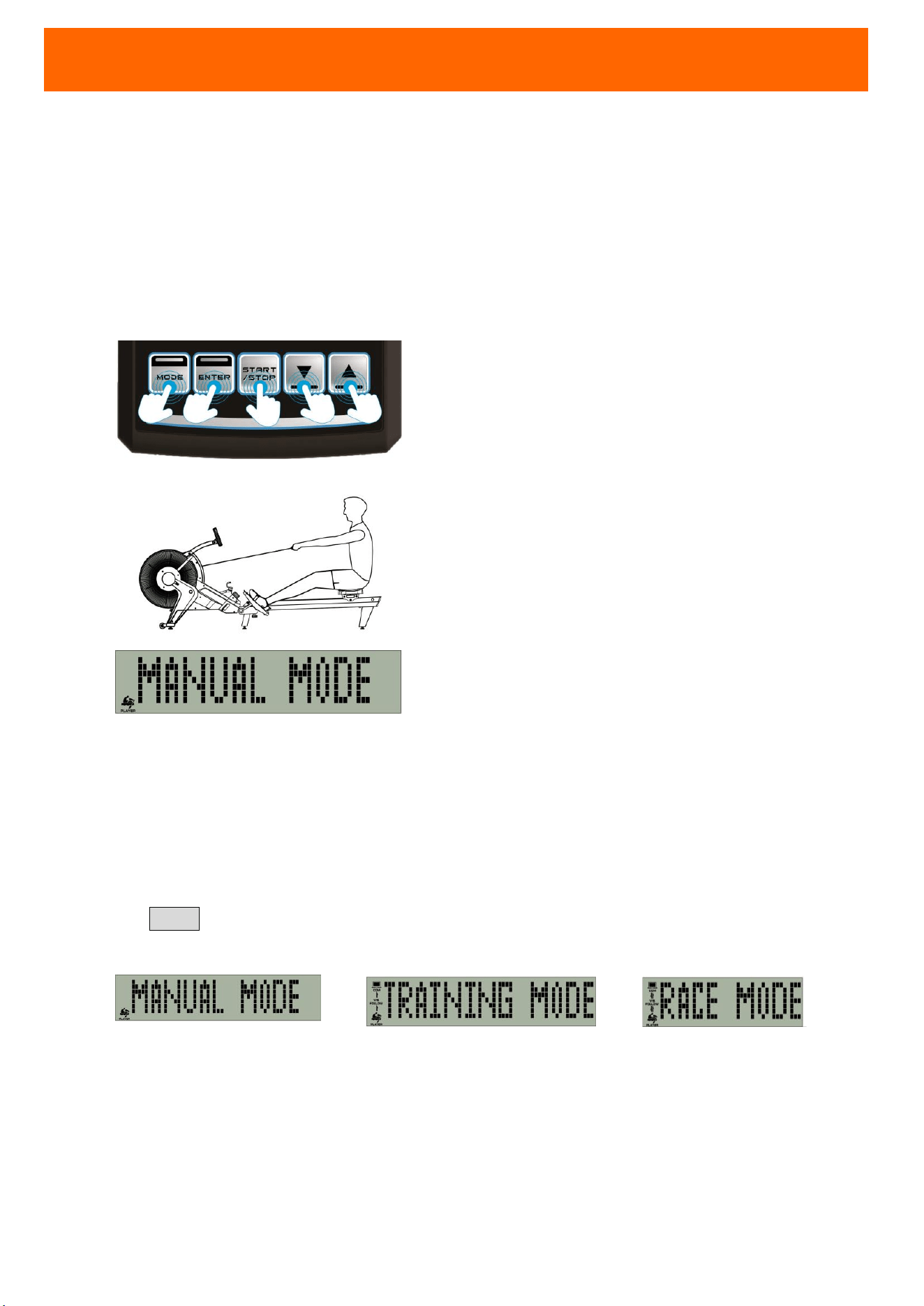
POWER
Use 2 batteries AA-size (UM-3) for console power supply.
TURN ON CONSOLE
Press any console button to turn on console.
Or, start exercise to turn on console.
Then, the machine will go into 「Manual Mode. 」
SLEEP STATE
It will go into SLEEP MODE (power-saving) automatically if no input or exercise within 4 minutes.
3 BUILT-IN EXERCISE MODES
Press MODE. You can select preset modes for your exercise. You can adjust the setting at each
mode. The three built-in modes are:
Manual Mode
Training Mode Race Mode
BUILT-IN HEART-RATE RECEIVER
This rower has built-in wireless heart-rate receiver. Wireless chest strap is not included.
CONSOLE OPERATING INSTRUCTIONS
19
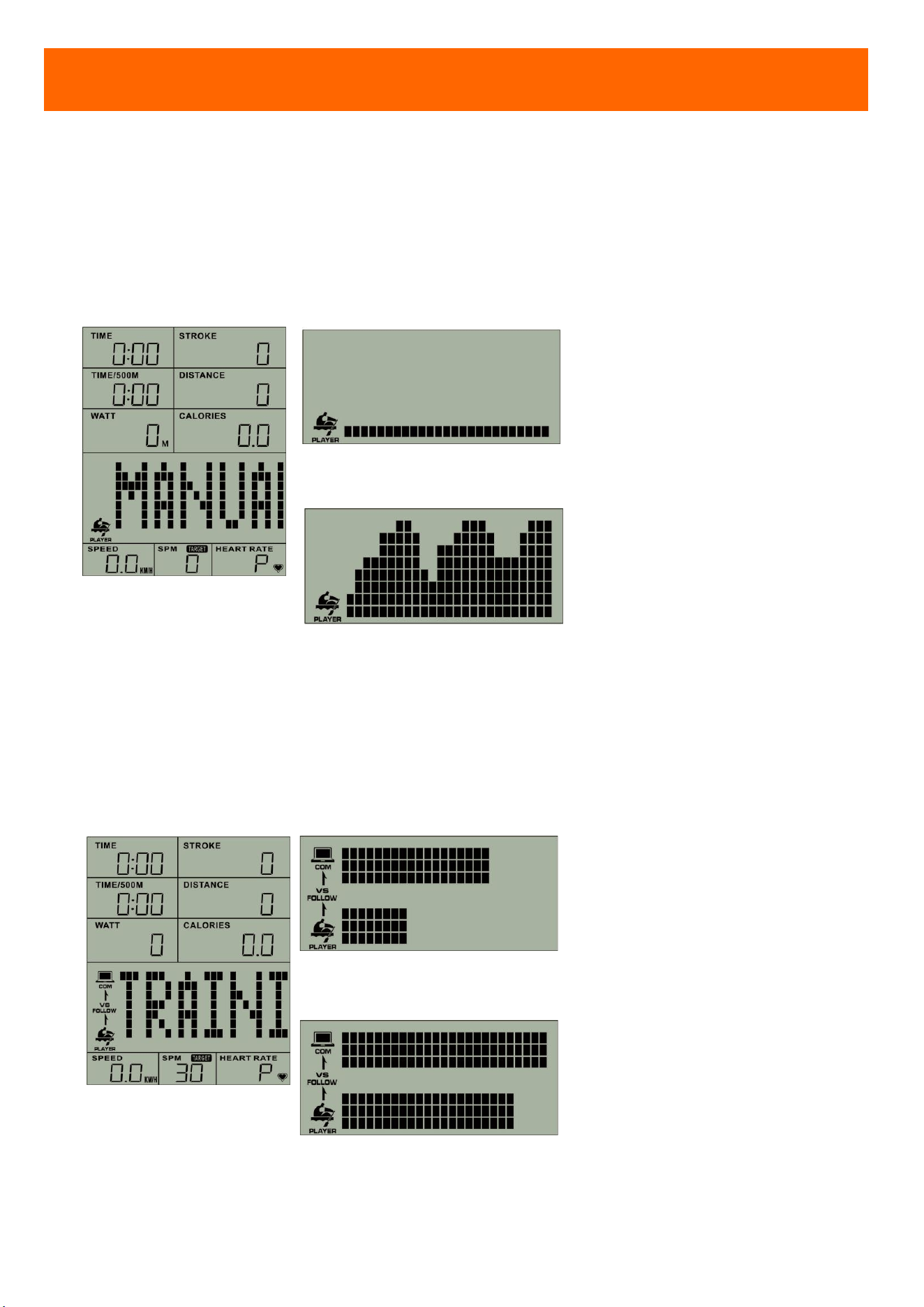
EXERCISE MODE
MODE & ICON EXERCISE
ADJUSTABLE SETTING
(range;increment;preset)
MANUAL MODE
After you
start exercise,
console will detect your
data.
Example 1
Example 2
Data display screen will show
STROKE-SPEED chart, according
to speed of your stroke.
STROKE
(0~99999;±10;0)
TIME
(0:00~99:59;±1:00;0:00)
DISTANCE
(100~99900;±100;500M)
NOTE:You select one setting for
your exercise.
TRAINING MODE
You can follow the display
screen guide to row
. The
purpose of this mode is to
Training Example 1
Training Example 2
Upper display screen will show
the computer rowing guide.
SPM
(20~80;±1;30 SPM)
STROKE
(0~99999;±10;0)
TIME
(0:00~99:59;±1:00;0:00)
CONSOLE OPERATING INSTRUCTIONS
20
train your rowing stability.
Lower will show your exercise.
You can check your exercise to
meet training target or not.
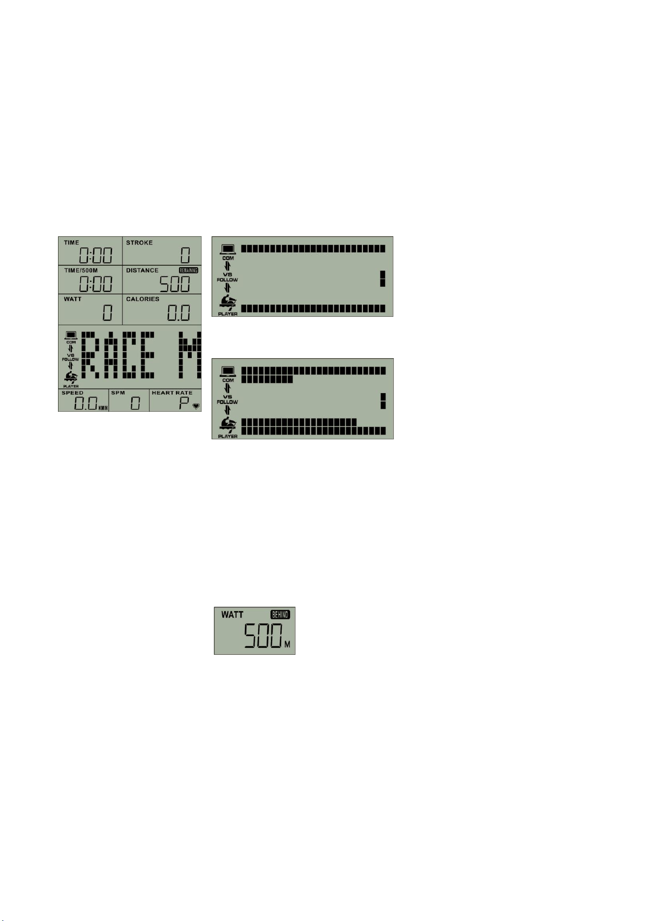
RACE MODE
Race with machine.
Race Example 1
Race Example 2
Upper display screen will be
machine distance, and the lower
will be your distance. Right side of
screen will be the end. Winner is
the first to the end point.
After Competition, WATT display
screen will show your ahead /
behind distance.
DISTANCE
(100~99900;±100;500M)
Competition
(L1~L5;±1;L3)
[L1
is low speed; L5 is the high
speed.]
21
FUNCTIONS
EXERCISE MODE
You may press MODE to select modes.
Console will show as
「 MANUAL MODE 」→「TRAINING
MODE」→「 RACE MODE」→「 MANUAL
MODE」→ …
Hold START/STOP for 3 sec, console will
clean all exercise data and back to
MANUAL MODE.
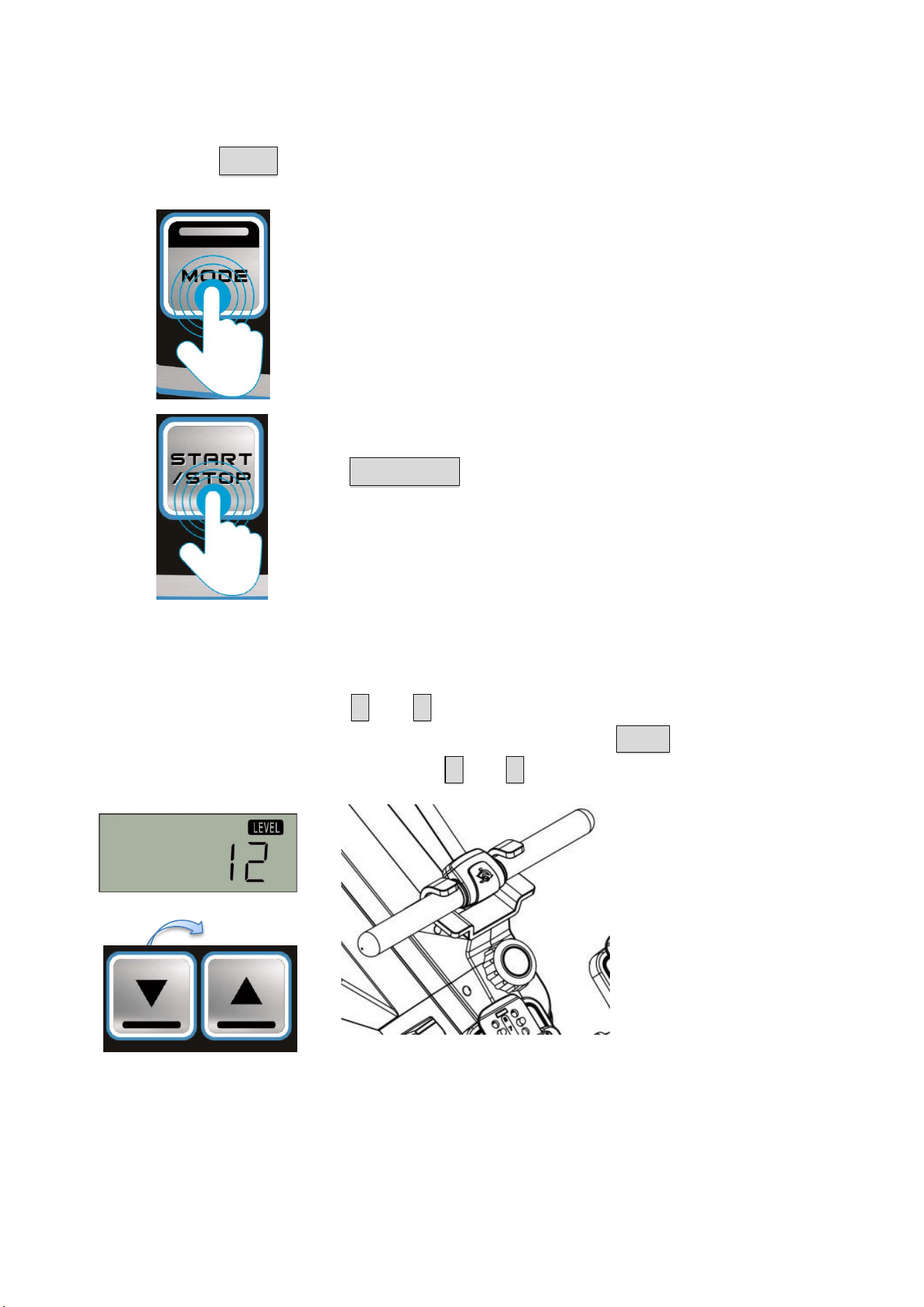
RESISTANCE LEVEL SETTING (OPTION FUNCTION)
Before your program, press ▲UP / ▼DOWN to adjust your level. Please make the 「LEVEL」
adjustment same as the machine resistance knob. Then, press ENTER to confirm.
During exercise (at START STATE), press ▲UP / ▼DOWN to adjust console resistance level.
(LEVEL: 1-12)
(LEVEL UP / DOWN)
After adjusting the resistance using the console and machine resistance knob, console can
calculate more accurate data for SPEED, WATT, CALORIES…and so on.
22
TRAINING TARGET SETTING (OPTIONAL)
After selecting training program, press ENTER to program target setting. The setting you select
will flicker.
You may press UP or DOWN to adjust your setting. Then, press ENTER to confirm.
NOTE: All adjustment is for one time. After console re-starting or selecting other mode, all
data will be back to preset.
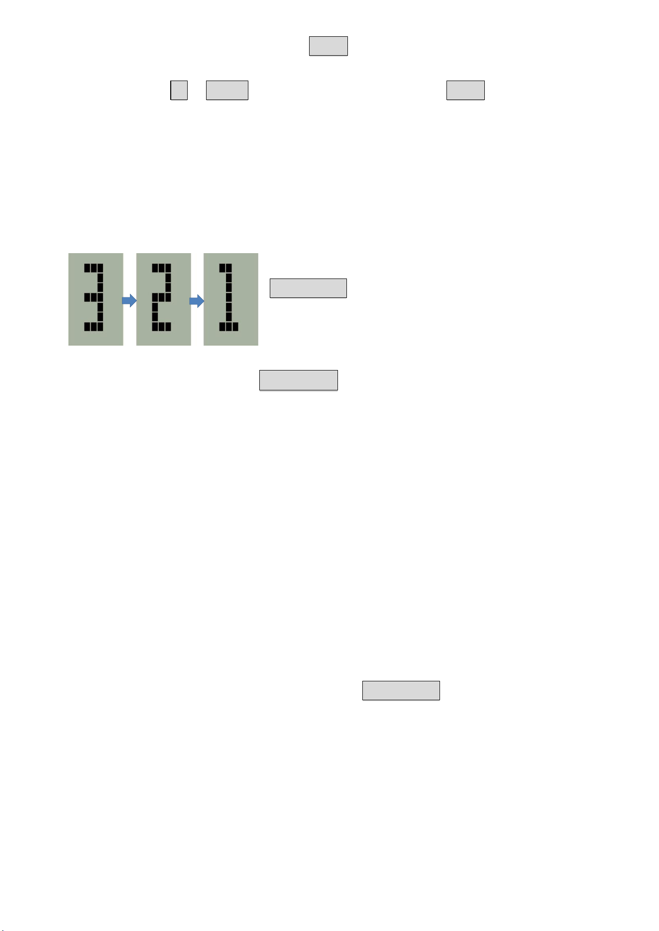
START / PAUSE / RESUME / END PROGRAM
After selecting mode and confirm target setting, please press
START/STOP. Console will count down 「3→2→1」and start
your program (console will be at START STATE
). You may
control the program as below:
During the program, press START/STOP to pause program (console will be at PAUSE
STATE). Console will stop counting, and show 「PAUSE」.
NOTE:
1. In MANUAL MODE, at PAUSE STATE, 「SPEED」will show your last stroke SPEED and AVG
SPEED.
2. At TRAINING MODE, at PAUSE STATE, 「SPM」will show TARGET SPM and AVG SPM; 「SPEED」
will show your last stroke SPEED and AVG SPEED.
3. At RACE MODE, at PAUSE STATE, 「WATT」will show WATT and your AHEAD / BEHIND
DISTANCE; 「SPEED」 will show your last stroke SPEED and AVG SPEED. 「HEART RATE」
will show HEART RATE and Competition INTENSITY.
4. If selecting machine resistance setting, at PAUSE STATE, 「CALORIES」will show CALORIES
and LEVEL.
During program or PAUSE STATE, you may press START / STOP to end the program. Console will
be STOP STATE.
After finishing program, console will stop counting with a beep sound. Console will be STOP
STATE.
Display screen will show all your exercise data until console into SLEEP STATE.
23
ISSUE CAUSE INSPECTION and ELIMINATING
No Power On
(can’t turn on)
Battery Power
NOT enough
Replace two new batteries AA-size (UM-3), and make sure positive (+) and
negative (-) pole at the right position.
Display Off
Battery Power
NOT enough
Replace two new batteries AA-size (UM-3), and make sure positive (+) &
negative (-) pole at the right position.
Data does not
change (during
the exercise)
Console is
showing
「 PAUSE 」
or 「STOP」
When the screen is showing 「PAUSE」 or 「STOP」, console is at pause or
stop state.
You may press START to start, and TIME display screen will continue
counting. Console will continue to work.
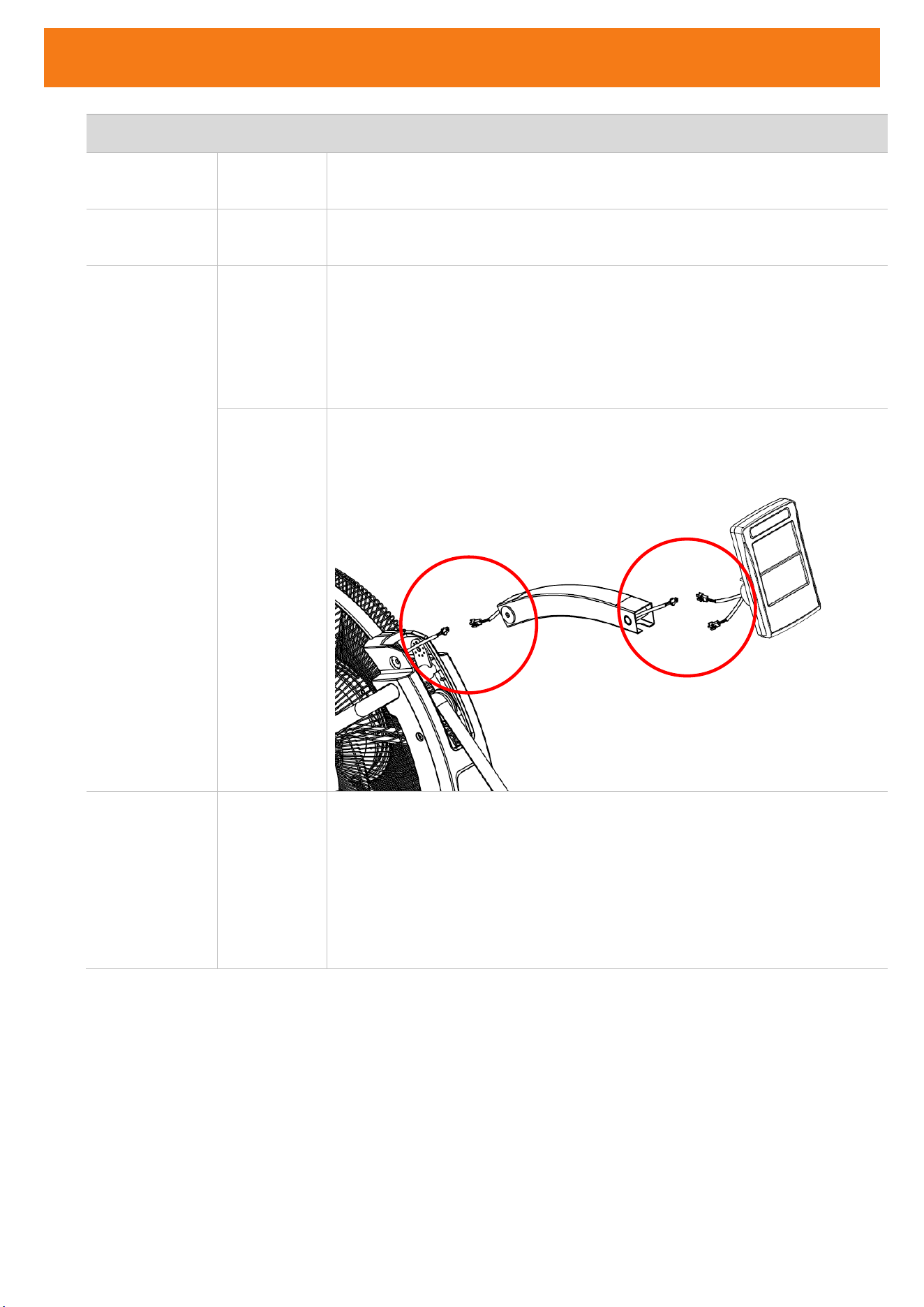
Speed sensor
NOT
connected
completely
When the screen is showing「TIME」, console is at start state. And, SPEED &
SPM display data will show “0.” This means console detect no exercise.
Please check and connect the console wire completely.
Suddenly no
display
Console NO
input for
long time
(into SLEEP
MODE)
Console is with power-saving function. It will go
into SLEEP MODE
automatically, if after 4 minutes of no input or exercise.
You may press any button or pull the handlebar more than 30cm to wake
up console.
TROUBLE SHOOTING
24
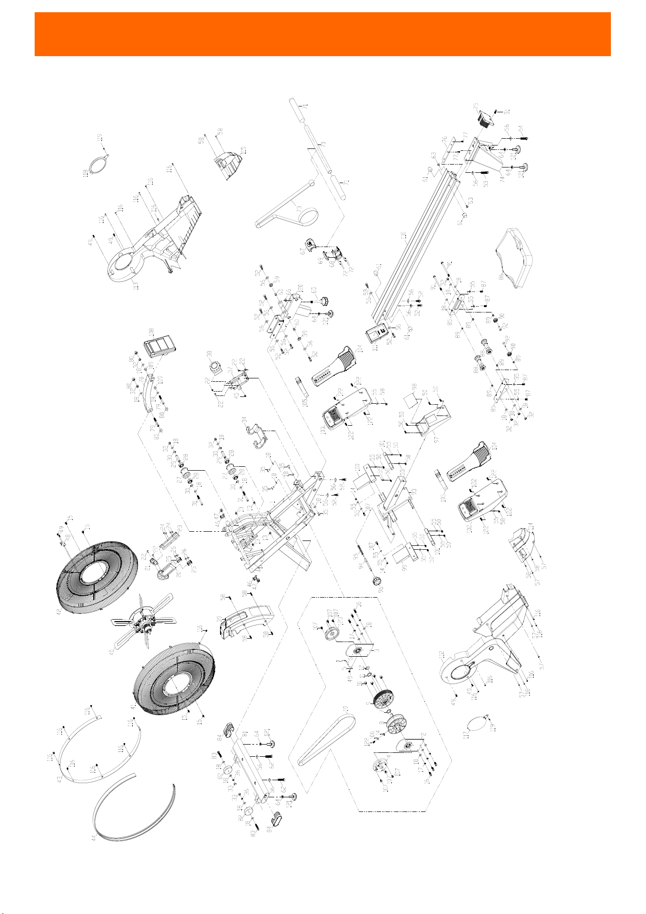
EXPLODED DIAGRAM

25
PART NO. Name Qty PART NO.
Name Qty
1
FRAME 1
63
WASHER 32*25.2*T2.0 1
2
BELT AXLE BRACKET 2
64
NUT M10*1.5*8t 5
3
SPEED SENSOR FIXED PLATE 1
65
KNOB 1
4
LEFT SCROLL SPRING SET
1
66
NUT M10*1.5*6t 1
5
SPEED SENSOR BRACKET 1
67
HANDLEBAR COVER - UPPER 1
6
SENSOR - DOWN 1
68
HANDLEBAR COVER - DOWN 1
7
CURVE WASHER 25.5*34*2.0T 1
69
HANDLEBAR ANTI-COLLISION COVER 1
8
ROPE WHEEL SET 1
70
ALUMINUM PIPE 1
9
BELT WHEEL SET 1
71
HANDLEBAR COVER 2
10
ROUND MAGNET 4
72
SCREW M3*10L 4
11
HANDLEBAR SPACER RING 1
73
SPECIAL ROPE 1
12
C25 CLIP 1
74
REAR STABILIZER 1
13
SCREW M5*8L 2
75
RAIL REAR COVER 1
14
NYLOCK NUT M6 3
76
RAIL PLATE 1
15
SCREW M5*12L 4
77
SCREW M8*16L 2
16
SCREW M8*20L 6
78
CONSOLE ARM 1
17
SPRING WASHER M8 6
79
SCREW M8*65L 2
18
WASHER M8*16*2.0 27
80
NUT 13MM 4
19
BELT 1
81
FRONT STABILIZER 1
20
MAGNET FIXED PLATE SET 1
82
MOVING WHEEL 2
21
MAGNET BRACKET 1
83
SCREW M8*45L 2
22
SCREW M5*16L 4
84
OVAL PIPE 2
23
GUIDE PLATE 1
85
SEAT FIXED PLATE 2
24
SCREW M5*8L 4
86
SEAT 1
25
MAGNETIC DRAG RAIL 2
87
SCREW M6*16L 4
26
SCREW M5*10L 4
88
UPPER PULLEY SET 2
27
GUIDE WHEEL 2
89
DOWN PULLEY SPACER RING 6
28
BEARING TPI6202 4
90
DOWN PULLEY 2
29
GUIDE SHAFT 2
91
SCREW M8*122 2
30
C15 CLIP 4
92
SCREW M8*25L 2
31
SCREW M8*75L 2
93
RAIL BRACKET SET 1
32
NYLOCK NUT M8 8
94
BOLT 1
33
CAP NUT M8 2
95
SPRING 1
34
HANDLEBAR FIXED SEAT 1
96
KNOB 1
35
SCREW M8*15L 4
97
RAIL BRACKET MIDDLE COVER 1
36
SPRING WASHER M8 2
98
STICKER 1
37
TRIMMING FIXED SET 1
99
LEFT PEDAL PIPE 1
38
TRIMMING KNOB 1
100
RIGHT PEDAL PIPE 1
39
ROPE GATE FRAME 1
101
REAR PEDAL PIPE 2
40
FAN COVER 1
102
LEFT PEDAL BRACKET 1
PARTS LIST

26
PART NO. Name Qty PART NO.
Name Qty
41
FAN LEFT COVER 1
103
RIGHT PEDAL BRACKET 1
42
FAN RIGHT COVER 1
104
HEEL SUPPORTER 2
43
FAN COVER TRIM 1
105
PEDAL BELT 2
44
TRIM PLATE 1
106
WASHER M6*20*1.5T 1
45
SCREW M4*12L 1
107
SCREW M6*16L 12
46
CHAIN TENSIONER 2
108
CONSOLE 1
47
WH NUT M10*1.5X14X8 2
109
PLASTIC PLUG 2
48
ROPE BRACKET 1
110
ALUMINUM RAIL 1
49
SCREW M4*8L 3
111
RAIL FRONT COVER 1
50
SCREW M6*10L 12
112
LEFT MAIN CASE 1
51
SCREW M6*20L 1
113
RIGHT MAIN CASE 1
52
SCREW M10*25L 12
114
LEFT CASE 1
53
SCREW M10*40L 1
115
RIGHT CASE 1
54
SCREW M10*50L 1
116
SCREW M4*16L 24
55
WASHER M6*16*1.5 18
117
LEFT MAIN COVER 1
56
WASHER M10*21*2.0 16
118
RIGHT MAIN COVER 1
57
SCREW M4*20L 5
119
SCREW M4*12 2
58
SCREW M5*12L 8
120
MIDDLE FIXED SET 1
59
RING 2
121
ADJUSTABLE FOOT 5
60
SPACER RING 2
122
SCREW M6*20L 9
61
RUBBER PAD 4
123
RIGHT SCROLL SPRING SET
1
62
SCREW M10*60L 2
Ordering Replacement Parts (U.S. and Canadian Customers only)
Please provide the following information in order for us to accurately identify the part(s) needed:
The model number (found on cover of manual)
The product name (found on cover of manual)
The part number found on the “EXPLODED DIAGRAM” and “PARTS LIST”
PARTS LIST

27