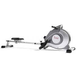
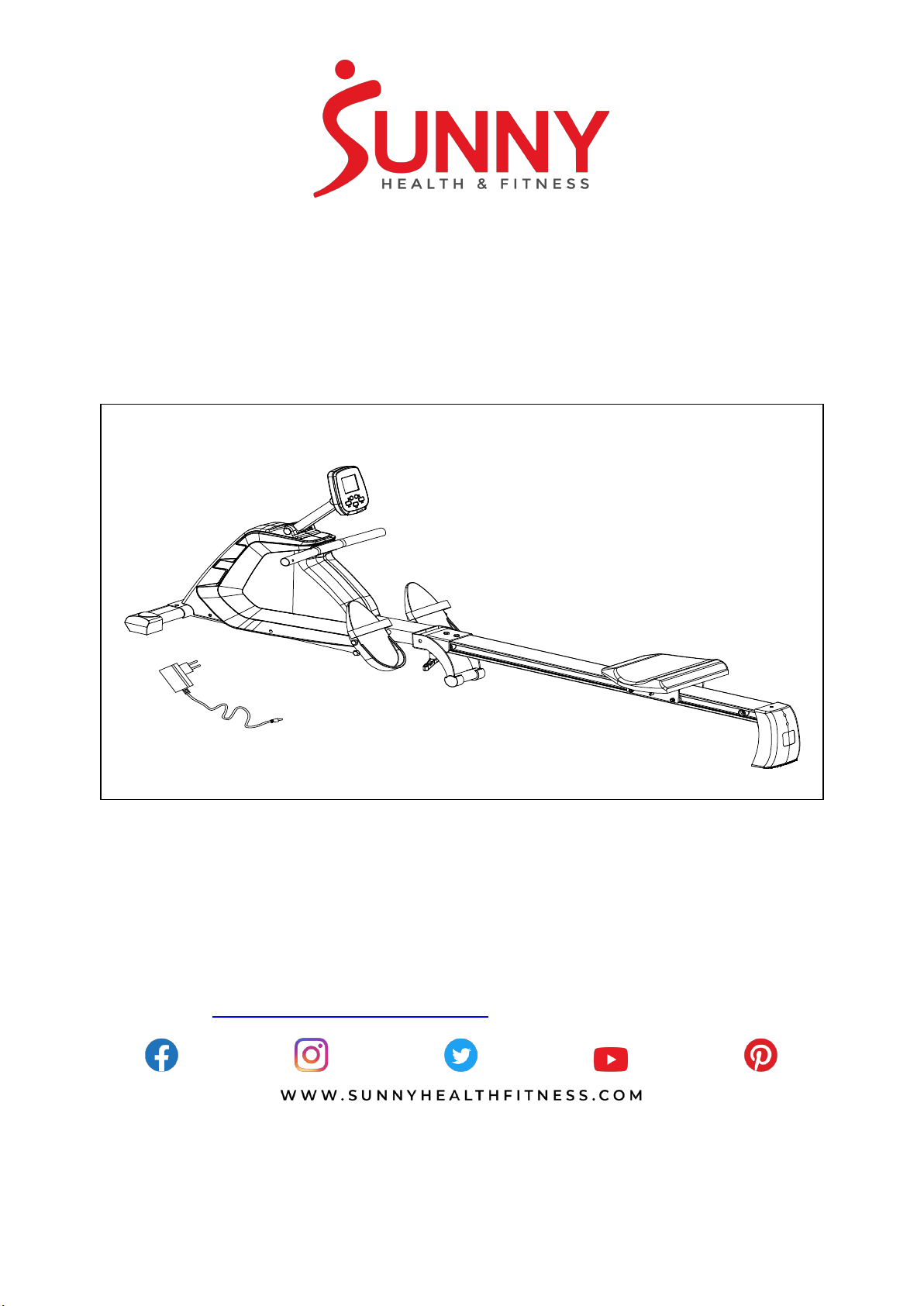
PROGRAMMABLE MAGNETIC ROWER
SF-RW5854
USER MANUAL
IMPORTANT! Please retain owner’s manual for maintenance and adjustment instructions. Your
satisfaction is very important to us, PLEASE DO NOT RETURN UNTIL YOU HAVE
CONTACTED US: support@sunnyhealthfitness.com or 1- 877 - 90SUNNY (877-907-8669).

1
IMPORTANT SAFETY INFORMATION
We thank you for choosing our product. To ensure your safety and health, please use this
equipment correctly. It is important to read this entire manual before assembling and using the
equipment. Safe and effective use can only be achieved if the equipment is assembled, maintained,
and used properly. It is your responsibility to ensure that all users of the equipment are informed of
all warnings and precautions.
1. Before starting any exercise program, you should consult your physician to determine if you
have any medical or physical conditions that could put your health and safety at risk or prevent
you from using the equipment properly. Your physician’s advice is essential if you are taking
medication that affects your heart rate, blood pressure, or cholesterol level.
2. Be aware of your body’s signals. Incorrect or excessive exercise can damage your health. Stop
exercising if you experience any of the following symptoms: pain, tightness in your chest,
irregular heartbeat, shortness of breath, lightheadedness, dizziness, or feelings of nausea. If
you do experience any of these conditions, you should consult your physician before continuing
with your exercise program.
3. Keep children and pets away from the equipment. The equipment is designed for adult use only.
4. Use the equipment on a solid, flat level surface with a protective cover for your floor or carpet.
To ensure safety, the equipment should have at least 2 feet (60CM) of free space all around it.
5. Ensure that all nuts and bolts are securely tightened before using the equipment. The safety of
the equipment can only be maintained if it is regularly examined for damage and/or wear and
tear.
6. Always use the equipment as indicated. If you find any defective components while assembling
or checking the equipment, or if you hear any unusual noises coming from the equipment during
exercise, discontinue use of the equipment immediately and do not use until the problem has
been rectified.
7. Wear suitable clothing while using the equipment. Avoid wearing loose clothing that may
become entangled in the equipment.
8. Do not place fingers or objects into the moving parts of the equipment.
9. The maximum weight capacity of this unit is 300 pounds (135 KG).
10. The equipment is not suitable for therapeutic use.
11. To avoid bodily injury and/or damage to the product or property, proper lifting and moving are
required.
12. Your product is intended for use in cool and dry conditions. You should avoid storage in extreme
cold, hot, or damp areas as this may lead to corrosion and other related problems.
13. This equipment is designed for indoor and home use only; it is not intended for commercial use.
2
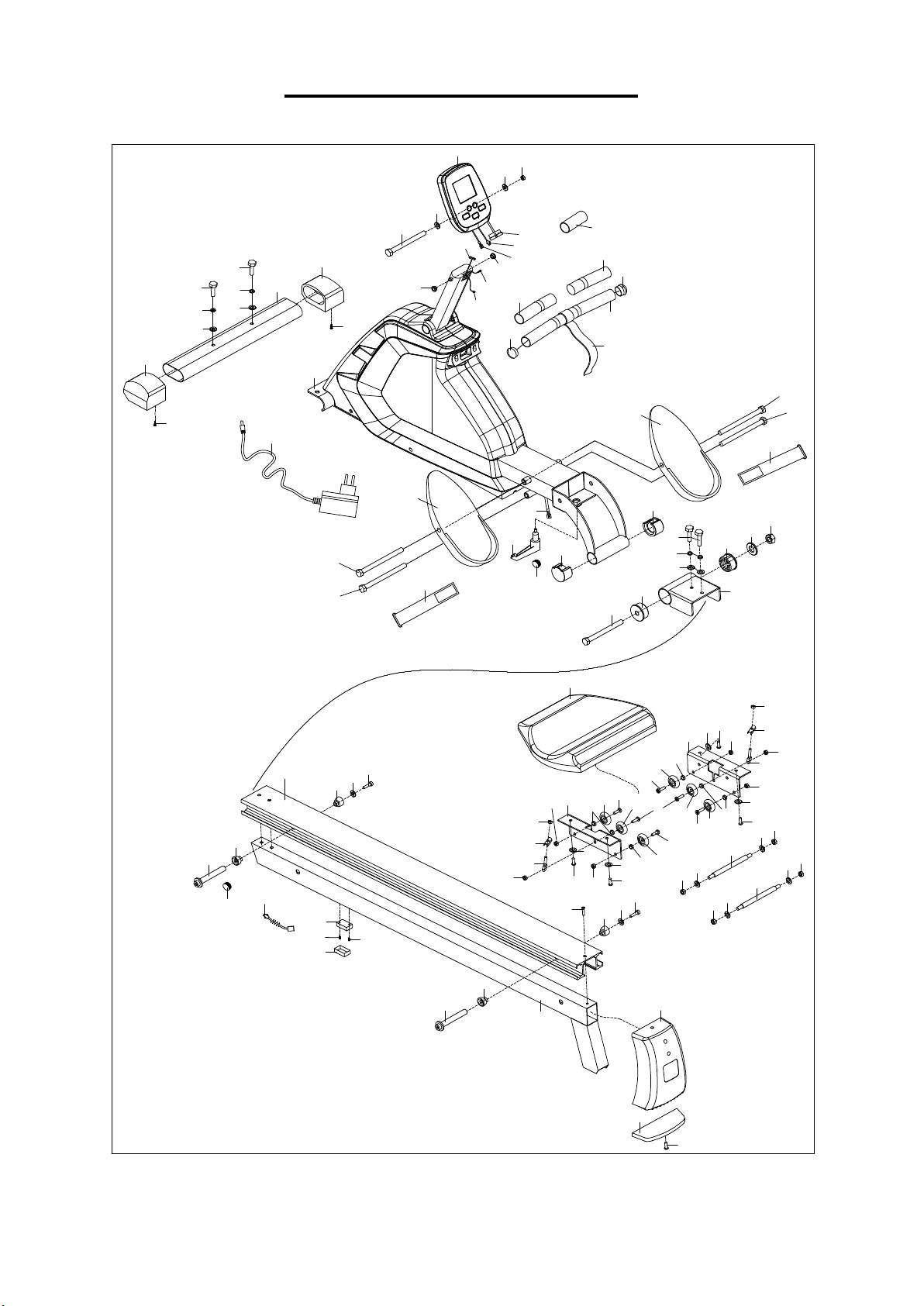
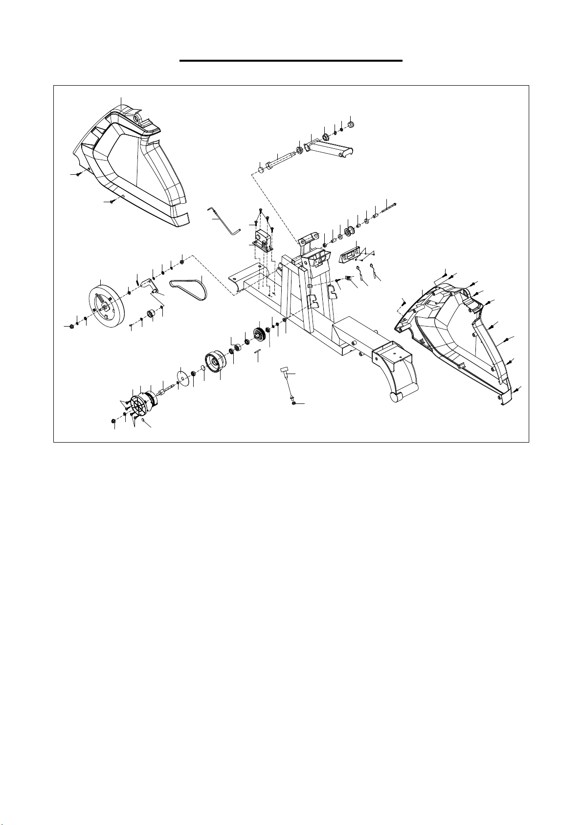
EXPLODED DIAGRAM 1
8
8
1
9
10R
10L
14
7
7
5
6
30
30
21
20
19
17
17
16
25
12
13
13
19
18
48
47
46
46
45
44
31
38
37
35
35
43
35
43
42
42
43
35
43
35
41
40
39
35
36
41
40
39
32
11
12
22
38
37
36
35
51
48
47
46
46
45
53
54
55
52
2
3
4
33
33
35
15
15
32
33
43
35
43
43
33
43
13
59
49
50
34
58
3
57
29
29
26
26
23L
23R
24
24
24
24
25
12
15
56
28
27
13
35
41
41
40
40
39
40
40
39
1a
1b
1c
F
3
EXPLODED DIAGRAM 2
64
63
62
106
106
2
3
105
105
104
77
77
77
77
77
76
77
77
76
77
76
76
88
78
80
79
87
82
81
83
85
86
80
78
79
80
78
79
78
79
67
110
61
60
73
71
70
74
72
71
70
69
75L
75R
66
96
101
95
94
89
90
91
92
93
99
103
98
97
98
102
80
84
65
100
68
107
108
109
111
103
108
4
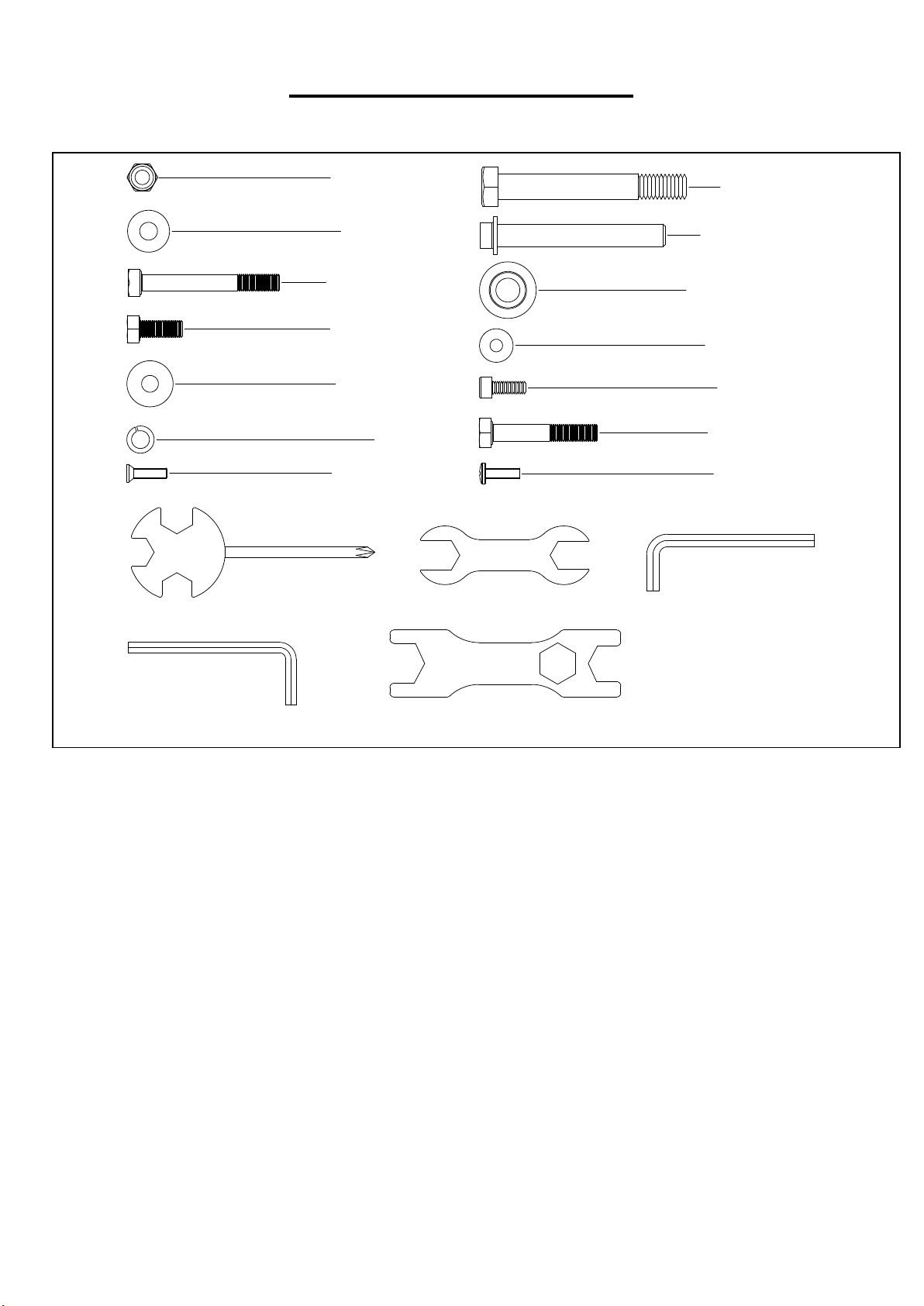
HARDWARE PACKAGE
#2 M8*H7.5*S13 1PC
#3 d8*Φ20*2 2PCS
#4 M8*90*20*S13 1PC
#11 M8*20*S13 2PCS
#12 d8*Φ22*2 4PCS
#15 d8 4PCS
#51 M5*16*Φ8.5 1PC
#24 M12*160 4PCS
#45 Φ10.9*80*14 1PC
#46 Φ11.4*Φ
27*26 2PCS
#47 d6*Φ16*1.2 1PC
#48 M6*16*S5 1PC
#25 M8*50*S14 2PCS
#55 M5*16*Φ10 1PC
#A S13-14-15 1PC
#D S13-14 1PC
#B S6 1PC
#C S5 1PC
#E S17-19 1PC

5
PARTS LIST
No. Description Spec. Qty.
No. Description Spec. Qty.
1 Computer 1 31 Seat 1
1a Computer Wire 1 32 Seat Post 2
1b Computer Wire 1 33 Bolt M8*16 4
1c Computer Wire 1 34 Bolt M8*32 2
2 Nylon Nut M8*H7.5*S13 2 35 Nylon Nut M8 10
3 Washer d8*Φ20*2 3 36 Adjusting Bolt M6*40 2
4 Bolt M8*90*20*S13 1 37 Adjusting U Seat 2
5 Handlebar 1 38 Nylon Nut M6 2
6 Mesh Belt 1 39 Spacer Φ12.5*Φ8.2*10 6
7 End Cap Φ32*17 2 40 Roller for Seat Slider 6
8 Foam Grip 2 41 Bolt M8*28 4
9 Front Stabilizer 1 42 Seat Axle 2
10L/R End Cap 2 43 Washer d8*Φ16*1.5 8
11 Bolt M8*20*S13 2 44 Aluminum Rail 1
12 Washer d8*Φ22*2 4 45 Axle Φ10.9*80*14 2
13 Screw ST4.2*25 4 46 Locating Mount Φ11.4*Φ27*26 4
14 Main Frame 1 47 Washer d6*Φ16*1.2 2
15 Spring Washer d8 4 48 Bolt M6*16*S5 2
16 L Knob 1 49
Upper Part of Heart
Rate Receiver
1
17 End Cap Φ38*28 2 50
Lower Part of Heart
Rate Receiver
1
18 Bolt M12*139 1 51 Bolt M5*16*Φ8.5 1
19 Bushing Φ50*3 2 52
Aluminum Rail
Support Frame
1
20 Washer d12*Ф24*2 1 53 Back Stand 1
21 Nylon Nut M12 1 54 Rubber Board 1
22 Aluminum Rail Link 1 55 Bolt M5*16*Φ10 1
23L/R Pedal 2 56 Trunk Wire 1
24 Bolt M12*160 4 57 Trunk Wire 3 1
25 Bolt M8*50*S14 2 58 Adapter 1
26 Bushing Φ16*2 2 59 Pulse Sensor Wire 1
27 Trunk Wire 4 1 60 Screw ST4.2*10 4
28 Trunk Wire 2 1 61 Motor 1
29 End Cap Φ22 2 62 Handlebar Seat 1
30 Pedal Strap 2 63 Washer d5*Φ10*1.0 2

6
No. Description Spec. Qty.
No. Description Spec. Qty.
64 Bolt M5*10 2
91
Axle for Mesh Belt
Wheel
1
65 Nut M12 1
92 Volute Spring 1
66 Belt 1
93
Outer PC Board for
Mesh Belt Wheel
1
67 Power Cord 1
94 Bearing 6300-2RS 1
68 Sensor Seat 1
95 C Clip d35 1
69 Bolt M10*112 1
96 Mesh Belt Plate 1
70 Spacer Φ19*2 2
97 Bearing 1
71 Bearing 6000-ZZ 2
98 Bearing 16003-2RS 2
72 Spacer Φ15*Φ10.2 1
99
Outer Cover for
Mesh Belt Wheel
1
73 Mesh Belt Pulley Φ45*35 1
100 Belt Wheel 1
74 Nylon Nut M10 1
101
Fixing Axle for Mesh
Belt
1
75L/R
Cover L/R 2
102 Bearing 6000-2RS 1
76 Screw ST4.2*16 4
103 Screw ST4.2*19 4
77 Screw ST4.8*16 8
104 Computer Post 1
78 Nut M10*1.0*H9.5 4
105 Bushing
Φ32*3.3*Φ28*16
2
79 Nut M10*1.0*H5 4
106
Computer Post
Cover
2
80 Washer d10*Φ20*2.0 4
107 Bolt Φ14*81.5*M8*S6
1
81
Idler Wheel Connect
Staff
1
108 Sensor Wire 2
82 Pulling Spring Φ2.2 1
109 Bolt M4*8 1
83 Idler Wheel 1
110
Resistance Control
Cable
1
84 Wave Washer d12*Φ15.5*0.3 1
111 Magnet Φ10*3 1
85 Washer d6*Φ16*1.5 1
A Spanner S13-14-15 1
86 Bolt M6*12 1
B Allen Wrench S6 1
87 Nut M10*1 1
C Allen Wrench S5 1
88 Inertial Wheel 1
D Spanner S13-14 1
89
PC Board for Mesh
Belt Wheel
1
E Spanner S17-19 1
90 Wave Washer d10*Φ15*0.3 1
F Paper Tube 1
Ordering Replacement Parts (U.S. and Canadian Customers only)
Please provide the following information in order for us to accurately identify the part(s) needed:
The model number (found on cover of manual)
The product name (found on cover of manual)
The part number found on the “EXPLODED DIAGRAM” and “PARTS LIST” (found near the front
of the manual
Please contact us at [email protected] or 1- 877 - 90SUNNY (877-907-8669).
7
ASSEMBLY INSTRUCTIONS
We value your experience using Sunny Health and Fitness products. For assistance with parts or
(877-907-8669).
d8*Φ22*2 2PCS#12
#25
M8*50*S14 2PCS
25
12
15
9
#15 d8 2PCS
#A S13-14-15 1PC
14
S14
25
12
15
1 4
A
B
#2 4 M1 2 *1 60 4P CS
#E S 17 - 19 1 PC
S 19
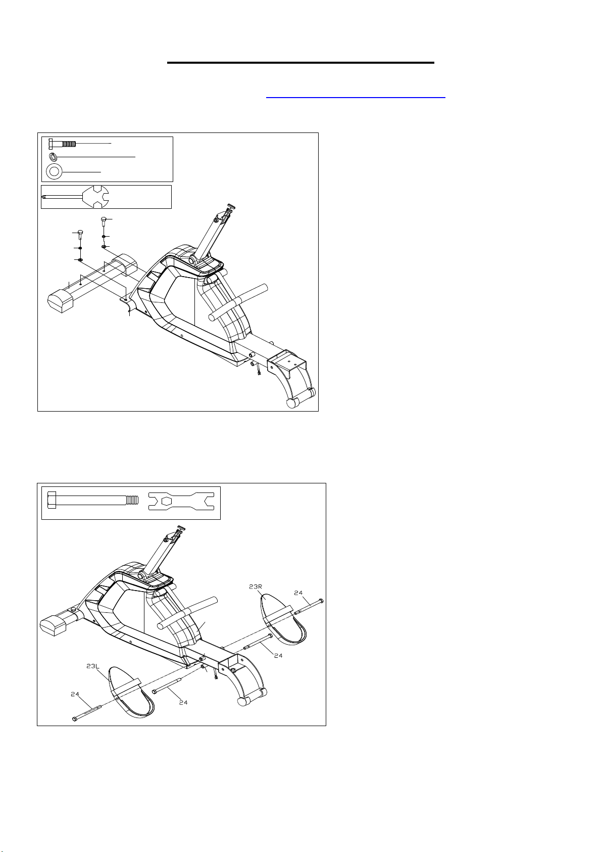
STEP 1:
Attach Front Stabilizer (No. 9) to Main
Frame (No. 14) using 2 Bolts (No. 25), 2
Spring Washers (No. 15), and 2 Washers
(No. 12). Tighten and secure with Spanner
(No. A).
STEP 2:
Insert the 2 Bolts (No. 24) into the bottom
hole in position B of the Main Frame (No.
14) and tighten with Spanner (No. E).
Insert the 2 Bolts (No. 24) into the upper
hole in position A of the Main Frame (No.
14) through the Pedals (No. 23L/R) and
tighten with Spanner (No. E).
NOTE: The Pedals (No. 23L/R) should
rest on the Bolts (No. 24) that are in
position B.
8
We value your experience using Sunny Health and Fitness products. For assistance with parts or
(877-907-8669).
d6*Φ16*1.2 1PC
#47
Φ10.9*80*14 1PC
#45
#48
M6*16*S5 1PC
Φ11.4*Φ27*26 2PCS
#46
46
48
47
46
45
51
55
#55 M5*16*Φ10 1PC
#51 M5*16*Φ8.5 1PC
44
31
53
#B S6 1PC
#A S13-14-15 1PC
S14
S13
S15
#C S5 1PC
44
57
59
d8*Φ22*2 2PCS#12
#11 M8*20*S13 2PCS
#15 d8 2PCS
16
14
59
57
22
11
12
15
#A S13-14-15 1PC
S13
57
16
22
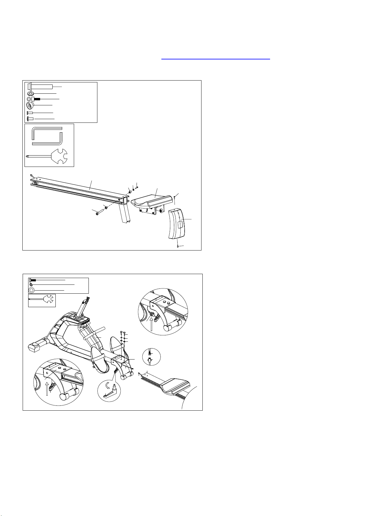
STEP 3:
Attach Seat (No. 31) onto Aluminum
Rail (No. 44).
Note: There is an arrow sticker marked
on Seat (No. 31), please attach it as the
arrow directs to prevent assembly in the
wrong direction.
Attach 2 Locating Mounts (No. 46) to
Aluminum Rail (No. 44) using 1 Axle
(No. 45), 1 Washer (No. 47) and 1 Bolt
(No. 48). Tighten and secure with Allen
Wrenches (No. B & No. C).
Attach Back Stand (No. 53) to
Aluminum Rail (No. 44) using Bolt (No.
51) and Bolt (No. 55). Tighten and
secure with Spanner (No. A).
STEP 4:
NOTE: To avoid damage to the wires,
please ensure that you keep the wires
beneath Main Frame (No. 14) and
Aluminum Rail (No. 44), away from the
connection point of the two sections.
Connect Trunk Wire 3 (No. 57) with
Pulse Sensor Wire (No. 59).
Attach Aluminum Rail (No. 44) into the
Aluminum Rail Link (No. 22) using 2
Bolts (No. 11), 2 Spring Washers (No.
15), and 2 Washers (No. 12). Tighten
and secure with Spanner (No. A).
Lift Aluminum Rail Link (No. 22)
upwards to suitable height, then tighten
and secure the Aluminum Rail Link
(No. 22) with L Knob (No. 16).
9
We value your experience using Sunny Health and Fitness products. For assistance with parts or
(877-907-8669).
4
56
27
1a
56
1c
27
28
1b
28
1
2
3
1b
1a
1c
#4 M8*90*20*S13 1PC
#3 d8*Φ 20*2 2PCS
#2 M8*H7.5*S13 1PC
#A S13-14-15 1PC
S13
3
104
S13
#D S13-14 1PC
27
28
56
58
F
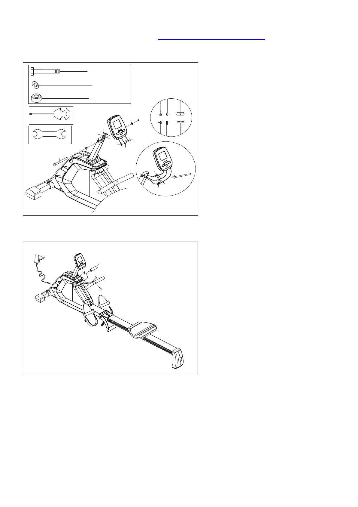
STEP 5:
Connect Trunk Wire (No. 56) with
Computer Wire (No. 1a).
Connect Trunk Wire 2 (No. 28) with
Computer Wire (No. 1b).
Connect Trunk Wire 4 (No. 27) with
Computer Wire (No. 1c).
Secure Computer (No. 1) to the
Computer Post (No. 104) using Bolt
(No. 4), 2 Washers (No. 3), and Nylon
Nut (No. 2) with Spanners (No. A & No.
D).
STEP 6:
Pull out the Handlebar (No. 5), then take
out the Paper Tube (No. F), and keep the
Mesh Belt (No. 6) in the middle of
Handlebar (No. 5), then put Handlebar
(No. 5) in the handlebar seat of Main
Frame (No. 14).
Insert one end of Adapter (No. 58) to the
power hole of Main Frame (No. 14),
connect another end of Adapter (No. 58)
with power.
When not in use, please put away Adapter
(No. 58) for your next use.
The assembly is complete!

10
EXERCISE COMPUTER
OPERATING INSTRUCTION:
1. Connect all of the cables to the computer.
2. After turning on, all LCD segments will light up for 2 seconds and the
Computer will start at level 1. The computer will go to initial mode.
NOTE: If the connection cables were installed incorrectly, motor will not
run.
Before asking service, please examine if all connection cables are well
connected and then reset the power to release the beep sound or press
DELETE button to restart system. If the motor still does not run, please
contact customer service.
If the computer shows “E2” message, please contact customer service.
KEY FUNCTION:
MODE:
1. During the stop mode, press MODE button to enter desired program.
2. Press MODE button to confirm the setting values of TIME, COUNT, DISTANCE, CALORIES,
PULSE in setting mode, or to confirm the PROGRAM PROFILE in User program.
RESET:
1. Press RESET button to clear all setting data to 0 or the default value.
2. Press RESET button for 2 seconds to enter initial mode and reset all values to 0.
RECOVERY:
Press RECOVERY to enter recovery mode.
F1.0 = Excellent F2.0 = Good F3.0 = Fair F4.0 = Below Average
F5.0 = No Good
(User needs wireless belt to use this function. This product does not include wireless belt.)
+ :
1. During the stop mode, select program or increase the setting value of TIME, COUNT,
DISTANCE, CALORIES, PULSE in the pulse program 9, or increase PROGRAM PROFILE in
the User setting program.
2. During the exercise mode, press this button to increase the load level.
- :
1. During the stop mode, select program or decrease the setting value of TIME, COUNT,
DISTANCE, CALORIES, PULSE in the pulse program 9, or decrease PROGRAM PROFILE in
the User setting program.
2. During the exercise mode, press this button to decrease the load level.
RESET RECOVERY
MODE
F6.0 = Poor

11
FUNCTIONS:
TIME:
Exercise time will be shown on the display when exercising. If the computer is inactive for 256
seconds, it will enter sleep mode. To turn on the computer, press any button or signal input or start
work out, all values will reset to zero.
Count up: Without setting the time value, the computer will count up the time from 0:00 to 99:59.
Count down: Setting the exercise time, the computer will count down from your setting value. Once
reach setting value, the computer will produce beep sounds and then stop. Press any button to
count up from 0:00.
DISTANCE:
The distance will be displayed on the window. The computer begins to calculate from 1 to 999 and
the measure unit is 1 (mile/1000). After reach 1 mile, the measure unit become to 0.1 mile. The
computer will display from 1.0 mile to 99.9 miles.
Count up: Without setting the distance value, the computer will count up from 0.1-99.9 miles.
Count down: Setting the exercise distance, the computer will count down from your setting value.
Once reach setting value, the computer will produce beep sounds and then stop. Press any button
to count up from 1 (mile/1000).
CALORIES:
The calories burned will be displayed on the window. Its scope is 0.0-999 kcal.
Count up: Without setting the calories value, the computer will count up from 0.0 to 999 kcal.
Count down: Setting the calories consumption, the computer will count down from your setting
value. Once you reach the setting value, the computer will produce beep sounds and then stop.
Press any button to count up from 0.0.
COUNT:
Count will be shown on the display when exercising. If the computer is inactive for 256 seconds, it
will reset to zero.
Count up: Without setting the count value, the computer will count up from 0 to 9999.
Count down: Setting the count value, the computer will count down from your setting value. Once
you reach the setting value, the computer will produce beep sounds and then stop. Press any
button to count up from 0.
PULSE:
The computer will display your current heartbeat rate in beats per minute, the range is 40-220. If
signal is input, the computer will count the beats. If no pulse input is detected within 6 seconds, the
display will indicate “p”. Pulse value will blink when the current pulse is higher than your default
value.
(Wear your wireless belt during this time. This product does not include the wireless belt.)
STROKES/MIN:
It means the number of strokes per minute.

12
PROGRAM:
Preset Program: Program 1- Program 7
1. Press the +/- buttons to the desired program.
2. Press MODE to enter the program.
3. The Time display will flash, and then press the +/- buttons to set up the desired time to do the
exercise. Press MODE button to confirm your setting value.
4. The count display will flash, and then press the +/- buttons to set up the desired value. Press
MODE button to confirm your setting value.
5. The distance display will flash, and then press the +/- buttons to set up the desired distance you
would like to reach. Press MODE button to confirm your setting value.
6. The calories display will flash, and then press the +/- buttons to set up the desired calories you
would like to reach. Press MODE button to confirm your setting value.
7. Pulse display will flash, and then press the +/- buttons to set up the desired pulse value you
would like to reach. Press MODE button to confirm your setting value.
8. Input the speed signal/pedal to start work out.
Note:
1. Press MODE button to the setting of next function.
2. There will be beep sounds when you reach the desired value.
If there is more than one desired value, press any button to continue work out after the beep, and
to reach next one.
PROGRAM 8 (COMPETITION PROGRAM)
1. Press the +/- buttons to program 8.
2. Press MODE button to enter the competition program.
3. The Time display will flash, and then press the +/- buttons to set up the desired time to do the
exercise. Press MODE button to confirm your setting value.
4. The distance display will flash, and then press the +/- buttons to set up the desired distance you
would like to reach. Press MODE button to confirm your setting value.
5. Input the speed signal/pedal to start work out.
Note:
1. Press MODE button to the setting of next function.
2. There are two parts of display: the upper and the bottom part.
The upper: unit work out distance, each bar means 1/10 of desired distance.
The bottom: unit work out time, each bar means 1/10 of desired time.
3. When the user reaches unit work out time, and the distance is less than unit work out distance.
The distance bars will flash and this means user does not reach the desired work out distance.
Otherwise, the bars will increase which means the work out is ok.

13
PROGRAM 9 (PULSE PROGRAM)
Computer will adjust the resistance level according to the pulse value, eg: if the current value is
lower than desired value, the resistance will increase, otherwise, the resistance will decrease.
1. Press the +/- buttons to program 9.
2. Press MODE button to enter the pulse program.
3. Pulse display will flash, and then press the +/- buttons to set up the desired pulse value you
would like to reach. Press MODE button to confirm your setting value.
4. The Time display will flash, and then press the +/- buttons to set up the desired time to do the
exercise. Press MODE button to confirm your setting value.
5. The count display will flash, and then press the +/- buttons to set up the desired value. Press
MODE button to confirm your setting value.
6. The distance display will flash, and then press the +/- buttons to set up the desired distance you
would like to reach. Press MODE button to confirm your setting value.
7. The calories display will flash, and then press the +/- buttons to set up the desired calories you
would like to reach. Press MODE button to confirm your setting value.
8. Input the speed signal/pedal to start work out.
Note:
If there is no desired pulse value in initial mode, the heartbeat is 90/mins.
There will be beep sounds when reach one of the desired value: TIME, COUNT, DISTANCE,
CALORIES, and the computer stops.
If there is more than one desired value, press any button to continue work out after the beep, and to
reach next one.
USER PROGRAM: (U1-U4)
1. Press the +/- buttons to U1-U4.
2. Press MODE button to enter the USER program.
3. The Time display will flash, and then press the +/- buttons to set up the desired time to do the
exercise. Press MODE button to confirm your setting value.
4. The count display will flash, and then press the +/- buttons to set up the desired value. Press
MODE button to confirm your setting value.
5. The distance display will flash, and then press the +/- buttons to set up the desired distance you
would like to reach. Press MODE button to confirm your setting value.
6. The calories display will flash, and then press the +/- buttons to set up the desired calories you
would like to reach. Press MODE button to confirm your setting value.
7. Pulse display will flash, and then press the +/- buttons to set up the desired pulse value you
would like to reach. Press MODE button to confirm your setting value.
8. Profile will flash, and then press the +/- buttons to set up the desired profile value you would like
to reach. Press MODE button to confirm your setting value. Setting in same way until finished all
profiles.
9. Input the speed signal/pedal to start work out.
Note:
1. There will be beep sounds when reach the desired value.
If there is more than one desired value, press any button to continue work out after the beep, and
to reach next one.
14
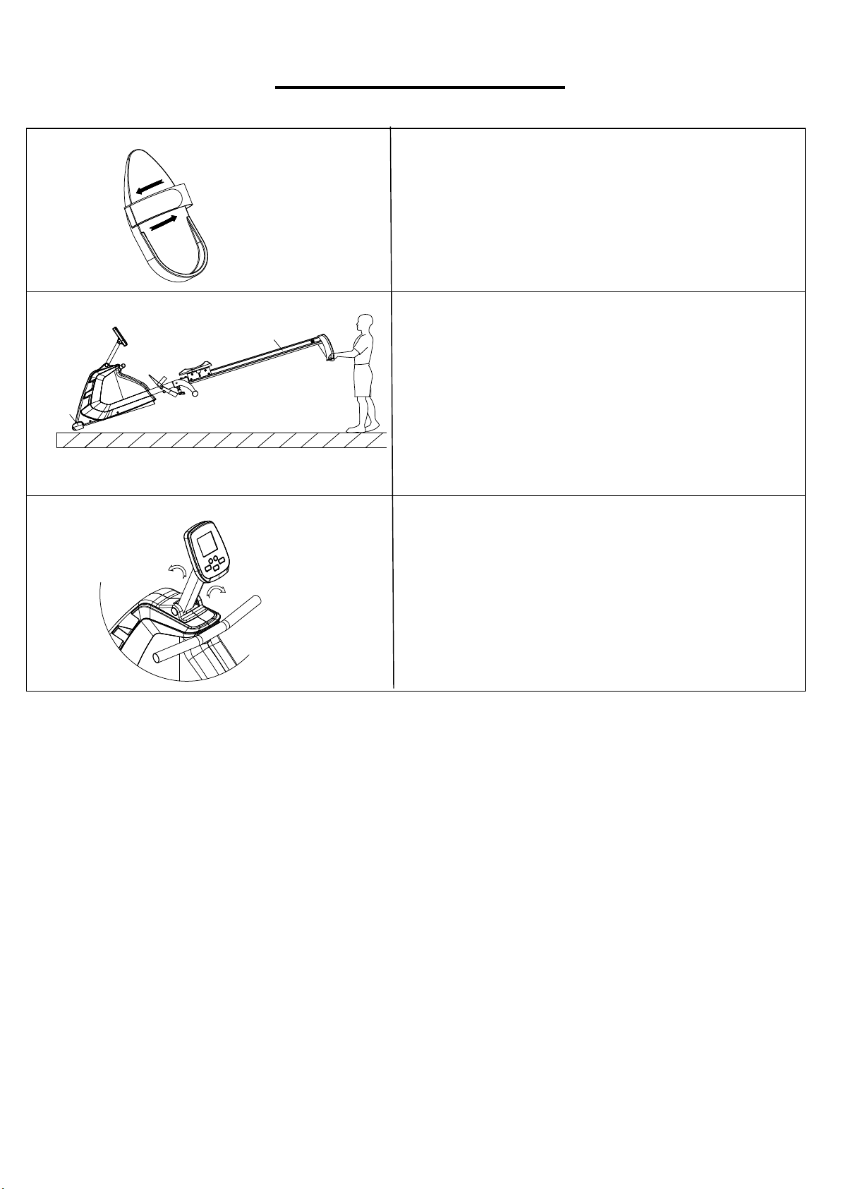
ADJUSTMENT GUIDE
10L/R
44
COMPUTER ANGLE ADJUSTMENT
The rotation angle of computer post can be adjusted
to obtain the best view of the Computer LCD screen.
PEDAL ADJUSTMENT
The pedal strap is adjustable and can be
personalized to fit the user’s foot size.
MOVING THE ROWER
To move the rower, lift up Aluminum Rail (No. 44)
until the transportation wheels on End Caps (No.
10L/R) touch the ground. With the transportation
wheels on the ground, you can transport the rower to
the desired location with ease.
15
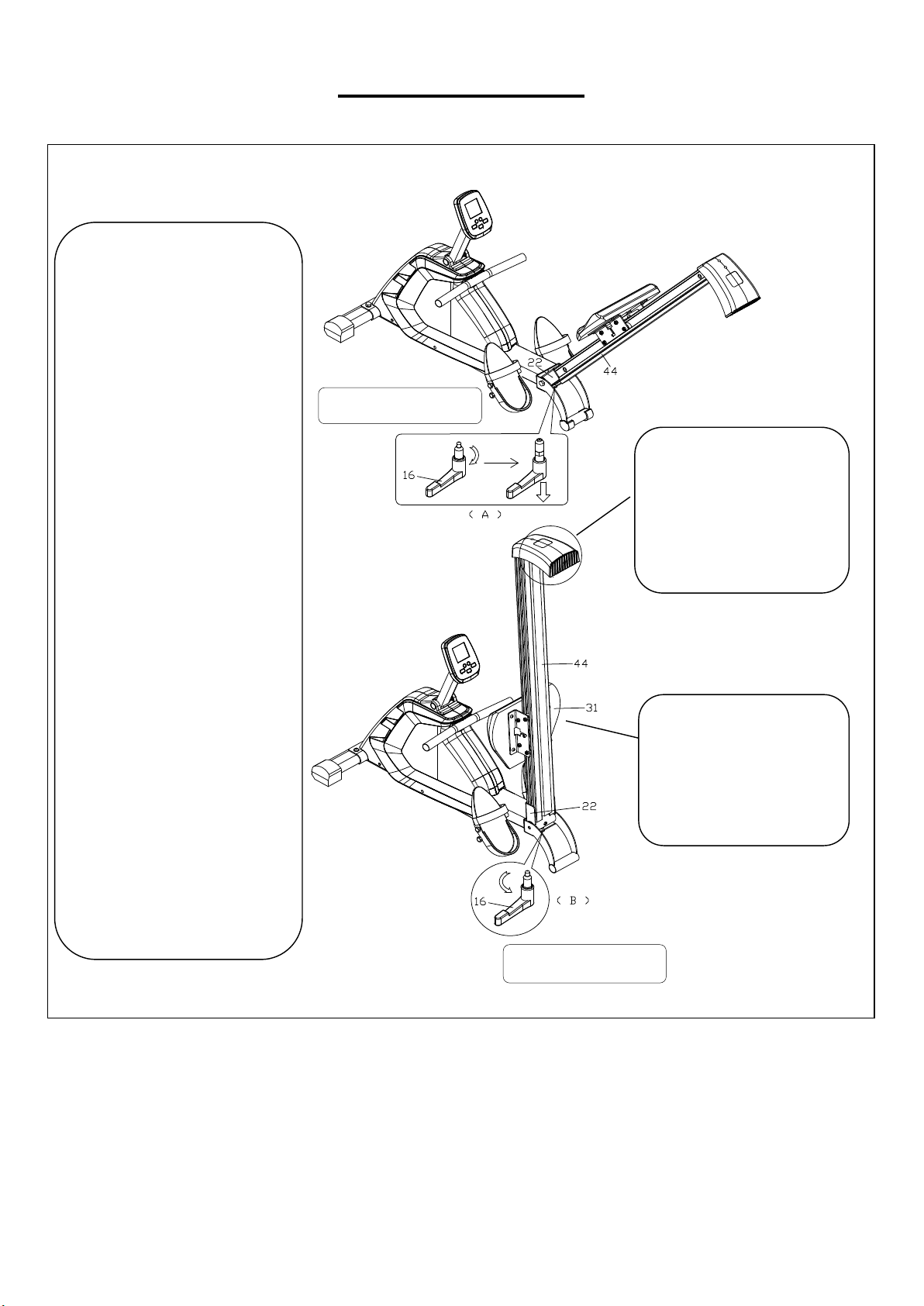
FOLDING GUIDE
When not in use, you can
save space by folding the
Aluminum Rail (No. 44).
1. Unscrew the L Knob
(No. 16) until the taper
completely with draws from
the Aluminum Rail Link
(No. 22), and at the same
time, draw the L Knob (No.
16) down until it cannot
move anymore. Then lift the
Aluminum Rail (No. 44) by
the other hand to an angle
until the L Knob (No. 16)
break away from the
Aluminum Rail Link (No.
22), and you can release
the L Knob (No. 16) now.
As shown in figure A.
2. When the Aluminum
Rail Link (No. 22) rotates to
a certain angle, the L Knob
(No. 16) will automatically fit
into the hole on the
Aluminum Rail Link (No.
22), after that screw the L
Knob (No. 16) tightly. As
shown in figure B.
Attention!
It is easy to hit your
head when the
Aluminum Rail (No.
44) is standing upright.
Attention!
The Seat (No. 31) will
slide down when folding
the Aluminum Rail
(No. 44).
Figure
A
Figure
B

16
TROUBLESHOOTING
Problem Possible cause Things to Check Solution
No sound or
display
1. Adapter or cables is loose. Check connection of plug.
Ensure the plug is well
connected.
2. The adapter does not fit
properly or power switch is off.
Check if power cord is
plugged in properly and
power switch is on.
Restart.
3. Computer crashed. Restart.
Partial display
Rubber connectors do not fit
well or PCB screws is loose.
Check if the rubber
connectors are in correct
position and if PCB screw is
tight.
Adjust rubber connector
to correct position and
tighten the screw on
PCB.
No heart rate
1. Poor detection of hand pulse
sensor plate.
Check if cables or wires are
poorly connected on hand
pulse sensor.
Replace the cables or
re-plug.
2. Faint signal from hand pulse
sensor.
Slightly wet your hands for
better signal.
Try again.
3. Bad detection from wireless
transmitter
Insert fresh battery into
wireless transmitter.
Try again.
4. Faint signal from ear clip
pulse sensor.
Rub your earlobe several
times and tuck ear clip behind
the earlobes.
Try again.
No speed
1. Computer does not receive
speed signals.
Check the speed sensor
cable.
Ensure speed sensor
cable is well connected.
2. The speed sensor does not
detect signal.
Check the gap between
speed sensor and magnet.
Ensure gap between
speed sensor and
magnet is less than 6
mm.
3. Defective sensor or poor
cable connection.
Check if sensor or cables is
damaged.
Replace the sensor or
cables.
4. The magnet has fallen off. Check placement of magnet. Reset the magnet firmly.
E1 (FOR PMS
ONLY)
1. The motor does not run.
Check if motor wires are well
connected or if motor is
stuck.
Replug the "t" again or
change the servo motor.
2. There is something wrong
with cables.
Check if cables are
damaged.
Replace the cables or
re-plug.
3. The computer can not supply
normal power to the motor.
Test whether the voltage of
motor is normal by pressing
"up" and "down".
Replace the computer.
E2
1. EEPROM has bad
connection.
Check if EEPROM IC is in
correct position.
Remove the IC and
re-plug.
2. The data of EEPROM is
damaged or IC is defective.
Check if the software of
EEPROM is correct.
Rewrite the software to
EEPROM again or
change the IC.
E4
No pulse signal when using the
body fat test.
Please refer to instructions in
"No heart rate".
Version 1.6

16