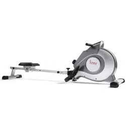
FULL MOTION MAGNETIC
ROWING MACHINE
SF-RW5864
USER MANUAL
IMPORTANT! Please retain owner’s manual for maintenance and adjustment instructions. Your
satisfaction is very important to us, PLEASE DO NOT RETURN UNTIL YOU HAVE CONTACTED
US: support@sunnyhealthfitness.com or 1- 877 - 90SUNNY (877-907-8669).

1
IMPORTANT SAFETY INFORMATION
We thank you for choosing our product. To ensure your safety and health, please use this equipment
correctly. It is important to read this entire manual before assembling and using the equipment. Safe
and effective use can only be achieved if the equipment is assembled, maintained, and used properly.
It is your responsibility to ensure that all users of the equipment are informed of all warnings and
precautions.
1. Before starting any exercise program, you should consult your physician to determine if you have
any medical or physical conditions that could put your health and safety at risk or prevent you from
using the equipment properly. Your physician’s advice is essential if you are taking medication that
affects your heart rate, blood pressure or cholesterol level.
2. Be aware of your body’s signals. Incorrect or excessive exercise can damage your health. Stop
exercising if you experience any of the following symptoms: pain, tightness in your chest, irregular
heartbeat, shortness of breath, lightheadedness, dizziness, or feelings of nausea. If you do
experience any of these conditions, you should consult your physician before continuing with your
exercise program.
3. Keep children and pets away from the equipment. The equipment is designed for adult use only.
4. Use the equipment on a solid, flat level surface with a protective cover for your floor or carpet. To
ensure safety, the equipment should have at least 2 feet (60CM) of free space all around it.
5. Ensure that all nuts and bolts are securely tightened before using the equipment. The safety of the
equipment can only be maintained if it is regularly examined for damage and/or wear and tear.
6. Always use the equipment as indicated. If you find any defective components while assembling or
checking the equipment, or if you hear any unusual noises coming from the equipment during
exercise, discontinue use of the equipment immediately and do not use until the problem has been
rectified.
7. Wear suitable clothing while using the equipment. Avoid wearing loose clothing that may become
entangled in the equipment.
8. Do not place fingers or objects into the moving parts of the equipment.
9. The maximum weight capacity of this unit is 265 pounds (120 KG).
10. The equipment is not suitable for therapeutic use.
11. To avoid bodily injury and/or damage to the product or property, proper lifting and moving are
required.
12. Your product is intended for use in cool and dry conditions. You should avoid storage in extreme
cold, hot or damp areas as this may lead to corrosion and other related problems.
13. This equipment is designed for indoor and home use only; it is not intended for commercial use.
2
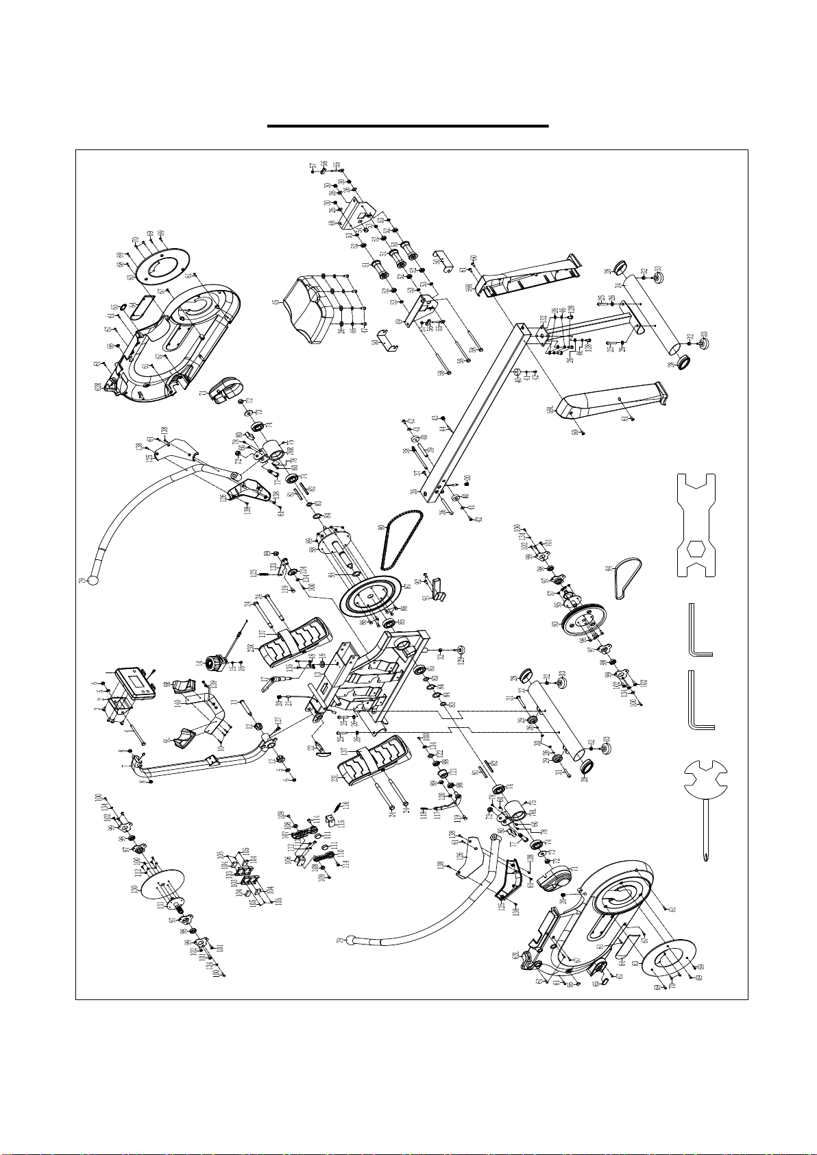
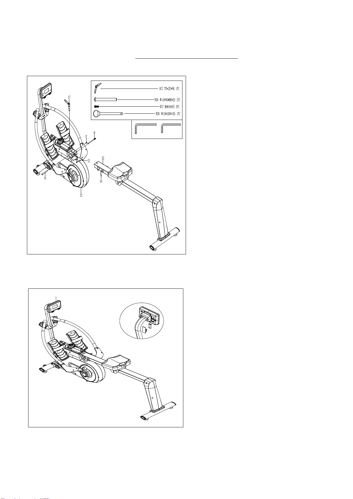
EXPLODED DIAGRAM
#A S13-14-15 1PC
#B S6 1PC
#D S17-19 1PC
#C S5 1PC
3
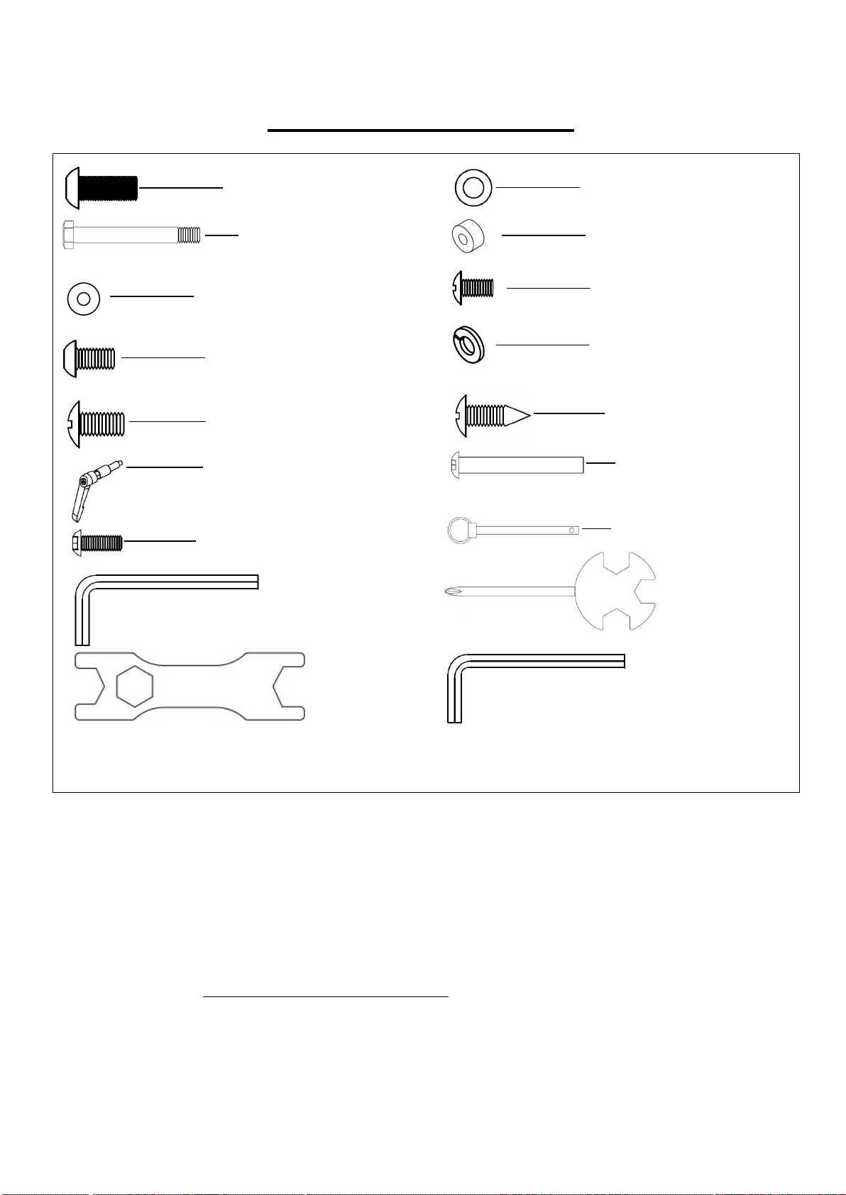
HARDWARE PACKAGE
Ordering Replacement Parts (U.S. and Canadian Customers only)
Please provide the following information in order for us to accurately identify the part(s) needed:
The model number (found on cover of manual)
The product name (found on cover of manual)
The part number found on the “EXPLODED DIAGRAM” and “PARTS LIST” (found near the front of
the manual)
Please contact us at [email protected] or 1- 877 - 90SUNNY (877-907-8669).
#25M8*20*S6 4PCS
#24 M12*Φ12.5*160*23*S19
4PCS
#26 d8*Φ16*1.5 8PCS
#40 Φ33*Φ8*13 1PC
#41 d6*Φ12*1.2 1PC
#42 M6*16*Φ12 1PC
#128M8*16*S6 4PCS
#46 d8 4PCS
#60 M4*10*Φ6 2PCS
#61 ST4.2*19*Φ8 2PCS
#17 111*22*96 1PC
#36Φ10*95*M6*25 1PC
#37 M6*16*S5 1PC
#38Φ10*100*105 1PC
#A S13-14-15 1PC
#C S5 1PC
#D S17-19 1PC
#B S6 1PC

4
PARTS LIST
No.
Description Spec. Qty.
No. Description Spec. Qty.
1 Computer 1
36 Bolt Φ10*95*M6*25 1
2 Computer Seat 1
37
Screw
M6*16*S5 1
3 Screw M5 4
38 Pull Pin Φ10*100*105 1
4 Bolt M8*90*20*S13 1
39 Limited Shaft Φ12*80*M6 1
5 Washer d8*Φ16*1.5 2
40 Limited Pad Φ33*Φ8*13 3
6 Nut M8*H7.5*S13 2
41 Washer d6*Φ12*1.2 3
7
Computer Joint
Tube
1
42 Screw M6*16*Φ12 3
8 Shaft Sleeve 2
43 Grommet Plug Φ16 1
9L/R
Rowing Rod Pad 2
44 Inductor 1
10 Screw ST4.2*19*Φ8 4
45 Seat 1
11 Bolt 1
46 Spring Washer d8 8
12 Shaft Sleeve Φ32*3*Φ28*16*Φ14.3
2
47 Bolt M8*16*S6 4
13 Main Frame 1
48
Right Support
Plate
1
14 Tension Knob 1
49
Left Support
Plate
1
15 Washer d5*Φ12*1.5 1
50 U Board 2
16 Screw M5*30*Φ8 1
51 Wheel Φ40*92 3
17 L Knob 111*22*96 1
52 Bearing 608Z 6
18 Limited Bracket 27*54*6.5 PP 1
53 Spacer d8*Φ15*4 6
19 Washer d12*Φ24*2 1
54 Magnet Φ15*7 1
20 Grommet Plug 3
55 Bolt M6*40*Φ10*2.5 2
21 Trunk Wire 2 1
56 U Bracket 2
22 T Knob 1
57 Nut M6*H6*S10 6
23L/
R
Pedal 2
58 Bolt M8*125*15*S14 3
24 Bolt
M12*Φ12.5*160*23*S
19
4
59L/R
Cover 2
25 Bolt M8*20*S6 4
60 Screw M4*10*Φ6 6
26 Washer d8*Φ16*1.5 17
61 Screw ST4.2*19*Φ8 15
27 Front Stabilizer 1
62L/R
Housing 2
28 End Cap ZT80*40 4
63 Cover 2
29
Transportation
Wheel
Φ48*22*Φ8*22 2
64 Cover 2
30 Nut M8*H7.5*S13 5
65 Hole Cover 2
31 Bolt M8*42*10*S6 2
66 Hole Cover 2
32 Bolt M8*H5.5*S14 5
67 Screw ST4.2*16*Φ8 6
33 Foot Pad Φ52*43*M8 4
68 Screw ST4.2*13*Φ8 1
34 Rear Stabilizer 1
69 Screw ST4*8*Φ7 6
35 Sliding Rail 1
70 Screw ST2.9*10*Φ6.3 4

5
No. Description Spec. Qty.
No. Description Spec. Qty.
71 Cover 2
108 Copper Bush 2
72 Nut M12*H11*S19 4
109 Screw M6*20*Φ10.5 2
73 Washer d12*Φ32*2.0 2
110
Magnet Fixed
Plate
1
74 Bearing Φ52*15*Φ25 4
111 Magnet Φ25*10 2
75 Screw M5*5 2
112 Spring Washer d6 6
76L/
R
Shaft Sleeve
Combination
2
113 Bolt M6*12*S10 2
77 Bolt Φ14*44*17*M12*16 2
114 Screw M5*10*Φ10 2
78 Screw ST4.2*19*Φ8.4 4
115
Strong Magnet
Connecting Plate
1
79 Rowing Rod 2
116 Spring Φ1.2*Φ13.2*62*N30 1
80
Limited Cushion of
Rowing Rod
2
117 Idler Wheel Shaft1
1
81 Spacer Iron 8*7*72 2
118 Spring Φ1.2*Φ13.2*62*N30 1
82 Spacer Iron 6*6*75 2
119 Bolt M8*12*Φ10*5*S12 2
83 Wave Washer d26*Φ34*0.3 3
120 Washer d12*Φ17*0.5 1
84 C Clip d25 4
121 Idler Wheel Φ39*Φ34*24 1
85 Bearing 6205-ZZ 2
122 Wave Washer d12*Φ15.5*0.3 1
86 Bolt M8*16*S13 6
123 Spring Φ1.5*Φ14.5*61*N21 1
87 Chain Wheel 1
124 Small Chain wheel
1
88 Chain Wheel Shaft
1
125 Cover 2
89 Nylon Nut 8
126 Cover 2
90 Chain 1
127 Trunk Wire 1 1
91 Limited Tube 1
128 Bolt M8*16*S6 4
92 Screw M6*25*Φ10 2
129 Foot Pad Φ38*48*M8 1
93 Belt Pulley 1
130 Aluminum Wheel 1
94 Belt 1
131
Belt Wheel Axle
Joint
1
95 Belt Pulley Shaft 1
132
Rear Supporting
Tube
1
96 Bolt M6*16*S10 4
133
Connecting Rod
Joint 2
1
97 Bearing Seat Φ72*11 4
134 Washer d6*Φ16*1.5 6
98 Bearing 6001-2RS 6
135 Screw M5*7*Φ10 2
99 Fixed Plate t1.5*56*76 4
136
N/A
-
100 Bolt M6*12*S10 10
137 Pedal Strap t1.6*25*850 2
101
Screw M6*8*Φ12 4
138 Screw ST4.2*19*Φ8 8
102 Screw M6*10*Φ12 8
139 Screw M6*12*Φ10.5 2
103
Magnet Location 45.5*130*10.5 2
140 Rod Support Plate
1
104 Magnet 4
A Spanner S13-14-15 1
105 Screw ST3*10*Φ5.6 6
B Allen Wrench S6 1
106 Adjusting U Plate 1
C Allen Wrench S5 1
107
Magnet Fixed
Plate
1
D Spanner S17-19 1
6
ASSEMBLY INSTRUCTIONS
We value your experience using Sunny Health and Fitness products. For assistance with parts or
troubleshooting, please contact us at s[email protected] or 1-877-90SUNNY (877-907-
8669).
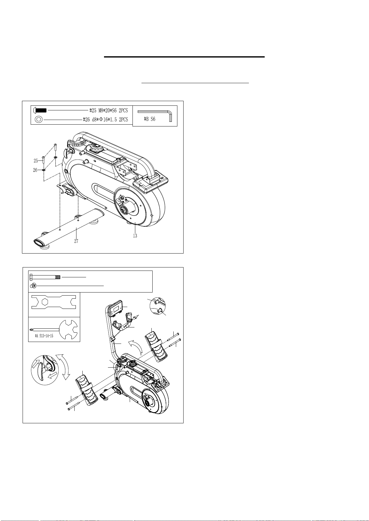
23R
24
#24 M12*Φ12.5*160*23*S19 4PCS
S19
#D S17-19
7
24
23L
13
1
22
24
24
139
#139 M6*12*Φ10.5 2PCS
140
A position
B position
Figure C
Tighten
Loosen
Pull
Put back
Figure C
STEP 1:
Attach Front Stabilizer (No. 27) to Main
Frame (No. 13) with 2 Bolts (No. 25) and2
Washers (No. 26).Tighten and secure with the
Allen Wrench (No. B).
STEP
2
:
Loosen T Knob (No. 22) as shown in Figure C
and pull outward. Next, rotate Computer Joint
Tube (No. 7) to the desired position and screw T
Knob (No. 22) into the hole. Finally, adjust
Computer (No. 1) up and down to the proper
angle.
Insert 2 Bolts (No. 24) into the bottom hole at
position B of Main Frame (No. 13). Tighten with
Spanner (No. D).
Insert 2 Bolts (No. 24) through the Pedals (No.
23L/R) into the upper hole at position A of Main
Frame (No. 13).Tighten with Spanner (No. D).
NOTE: The Pedals (No. 23L/R) should rest on
the bottom Bolts (No. 24) at position B.
Remove 2 Screws (No. 139) from Computer
Joint Tube (No. 7) with Spanner (No. A).
Attach Rod Support Plate (No. 140) to
Computer Joint Tube (No. 7) with 2 Screws
(No. 139) that were removed. Tighten and
secure with Spanner (No. A).
7
We value your experience using Sunny Health and Fitness products. For assistance with parts or
troubleshooting, please contact us at support@sunnyhealthfitness.com or 1-877-90SUNNY (877-
907-8669).
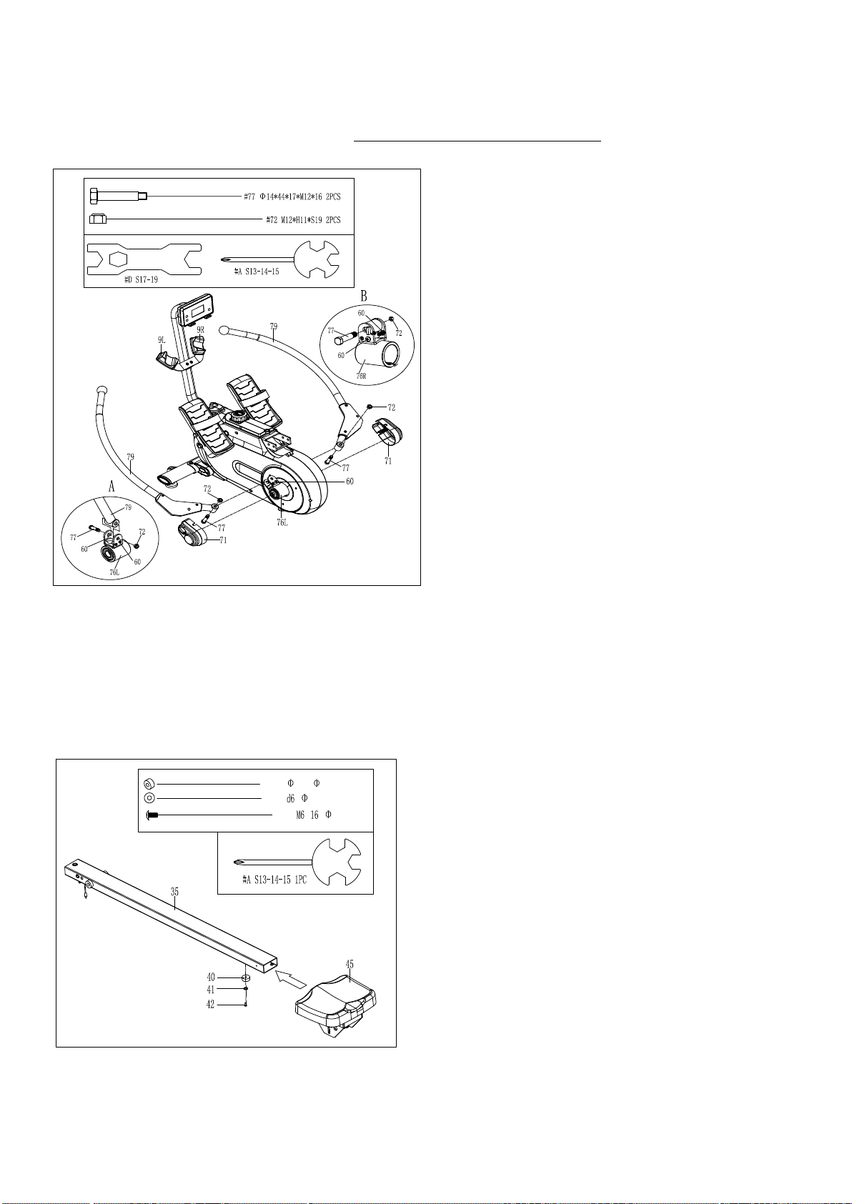
#40 33* 8*13 1PC
#41 * 12*1.2 1PC
#42 * * 12 1PC
STEP 4:
Insert Seat (No. 45) to Iron Rail (No. 35).
Attach Limited Pad (No. 40) to Sliding Rail
(No. 35) with Screw (No. 42) and Washer
(No. 41). Tighten and secure with the
Spanner (No. A).
STEP 3:
Loosen 4 Screws (No. 60) from Left & Right
Shaft Sleeve Combinations (No. 76L/R)
with Spanner (No. A).
Remove 2 Bolts (No. 77) and 2 Nuts (No.
72) from Left & Right Shaft Sleeve
Combinations (No. 76L/R) with Spanner
(No. D).
Put Rowing Rods (No. 79) into Left & Right
Shaft Sleeve Combinations (No. 76L &No.
76R) with 2 Bolts (No. 77) and 2 Nuts (No.
72) that were removed. Tighten and secure
with Spanner (No. D).
Note: Please check if Rowing Rod (No. 79)
rotates smoothly. If not, Bolt (No. 77) and
Nut (No. 72) are locked too tight. Adjust Nut
(No. 72) with Spanner (No. D) to make the
rotation smooth.
Put Rowing Rods (No. 79) on Left & Right
Rowing Rod Pads (No. 9L & No. 9R). Put 2
Covers (No. 71) into Left & Right Shaft
Sleeve Combinations (No. 76L & No. 76R)
with 4 Screws (No. 60) that were loosened.
Tighten and secure with Spanner (No. A).
8
We value your experience using Sunny Health and Fitness products. For assistance with parts or
troubleshooting, please contact us at s[email protected] or 1-877-90SUNNY (877-907-
8669).
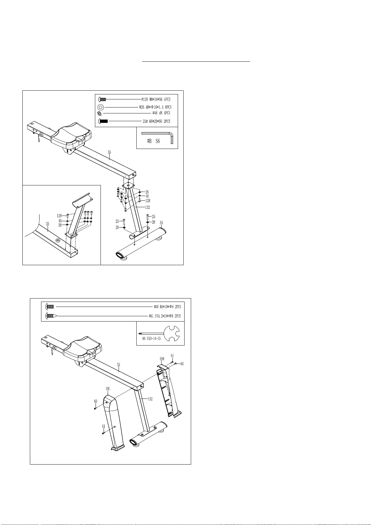
STEP 5:
Attach Rear Supporting Tube (No. 132) to
Sliding Rail (No. 35) with 4Bolts (No. 128),
4 Spring Washers (No. 46), and 4 Washers
(No. 26). Tighten and secure with the Allen
Wrench (No. B).
Attach Rear Stabilizer (No. 34) to Rear
Supporting Tube(No. 132) with 2 Bolts
(No. 25) and 2Washers (No. 26). Tighten
and secure with the Allen Wrench (No. B).
STEP 6:
Attach Left & Right Covers (No. 59L & No.
59R) to Sliding Rail (No. 35) and Rear
Supporting Tube (No. 132), then lock Left
& Right Covers (No. 59L & No. 59R) with 2
Screws (No. 61). Tighten and secure with
the Spanner (No. A).
Attach Left & Right Covers (No. 59L & No.
59R) to Sliding Rail (No. 35) with 2 Screws
(No. 60). Tighten and secure with Spanner
(No. A).
9
We value your experience using Sunny Health and Fitness products. For assistance with parts or
troubleshooting, please contact us at s[email protected] or 1-877-90SUNNY (877-907-
8669).
#B S6
#C S5
STEP 7:
Attach Sliding Rail (No. 35) to Main
Frame (No. 13) using Bolt (No. 36) and
Screw (No. 37). Tighten and secure with
Allen Wrench (No. B) and Allen
Wrench (No. C). Then insert Pull Pin
(No. 38).
Next, attach the top of Sliding Rail (No.
35) to Main Frame (No. 13) using L
Knob (No. 17).
Connect the link wire of Inductor (No.
44) with Trunk Wire 2 (No. 21).
STEP
8
:
Open the battery cover on the back of
Computer (No. 1), then put 2 batteries into
the battery case. Make sure the (-) end of
the battery goes to the spring end in the
battery compartment, then put the battery
cover back.
The assembly is complete!
10
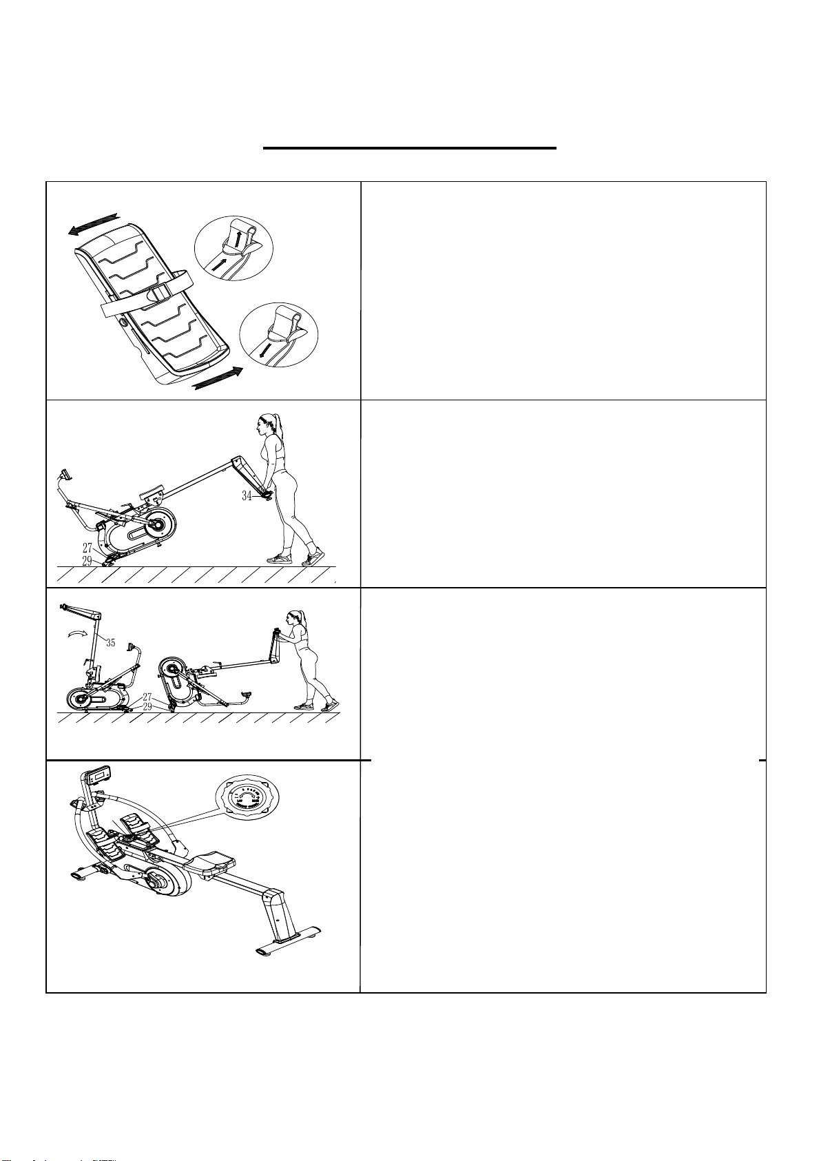
ADJUSTMENTS GUIDE
P u s h
Pull
Fig ur e A
Pu l l
Fig ur e B
1 4
PEDAL STRAP ADJUSTMENT
The Pedal Strap (No. 137) is adjustable and can
be personalized to fit the user’s foot size. Directions
on how to loosen and tighten the straps are shown
in figures A and B.
MOVING THE ROWER
To move the rower, lift up Rear Stabilizer (No. 34)
until the Transportation Wheels (No. 29) on Front
Stabilizer (No. 27) touch the ground. Once the
Transportation Wheels (No. 29) are on the
ground, you can transport the rower to the desired
location with ease.
Loosen
Tighten
MOVING THE ROWER
AFTER
FOLDING
Press down Sliding Rail (No. 35) until
Transportation Wheels (No. 29) on Front
Stabilizer (No. 27) touch the ground. Once the
Transportation Wheels (No. 29) are on the
ground, you can transport the rower to the desired
location with ease.
ADJUSTING THE RESISTANCE
Rotate the Tension Knob (No. 14) clockwise to
increase the level of resistance. Rotate the
Tension Knob (No. 14) counter-clockwise to
decrease the level of resistance.
Tension levels are set at Level 1 being the lowest
and Level 8 being the highest.
11
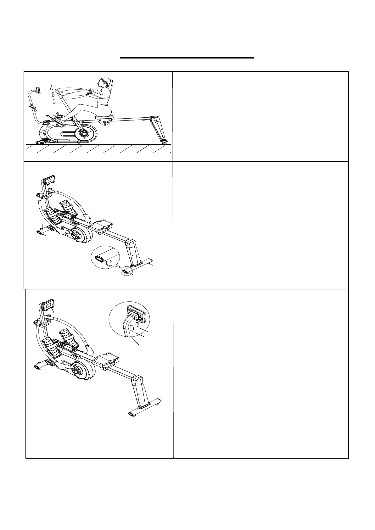
ADJUSTMENTS GUIDE
2 7
3 3
3 4
3 3
3 3
BATTERY
REPLACEMENT
To replace the batteries, open the battery cover
on the back of the Computer (No. 1). Remove
the batteries and replace with new batteries.
Make sure the (-) end of the battery goes to the
spring end in the battery compartment. Put the
cover back.
When changing batteries, always replace both
with new batteries. Do not mix old and new
batteries.
BATTERY DISPOSAL
Dispose the batteries according to the laws and
regulations of your local region. Some batteries
may be recycled. When disposing or recycling, do
not mix battery types.
ADJUSTING
THE BALANCE
In order to achieve a smooth and comfortable
ride, you must ensure that the stability of the
rower is secured. If you notice that the rower is
unbalanced during use, you should adjust the
Foot Pads (No. 33) located beneath the Front
& Rear Stabilizers (No. 27 & No. 34). To do so,
simply rotate the Foot Pads (No. 33) until the
rower becomes level with the floor surface.
ADJUSTING THE RESISTANCE OF THE
ROWING ROD
The resistance is different at positions A, B, C,
etc. The closer you are to positions A, the lighter
the resistance.
1
1
Battery
Battery Cover
12
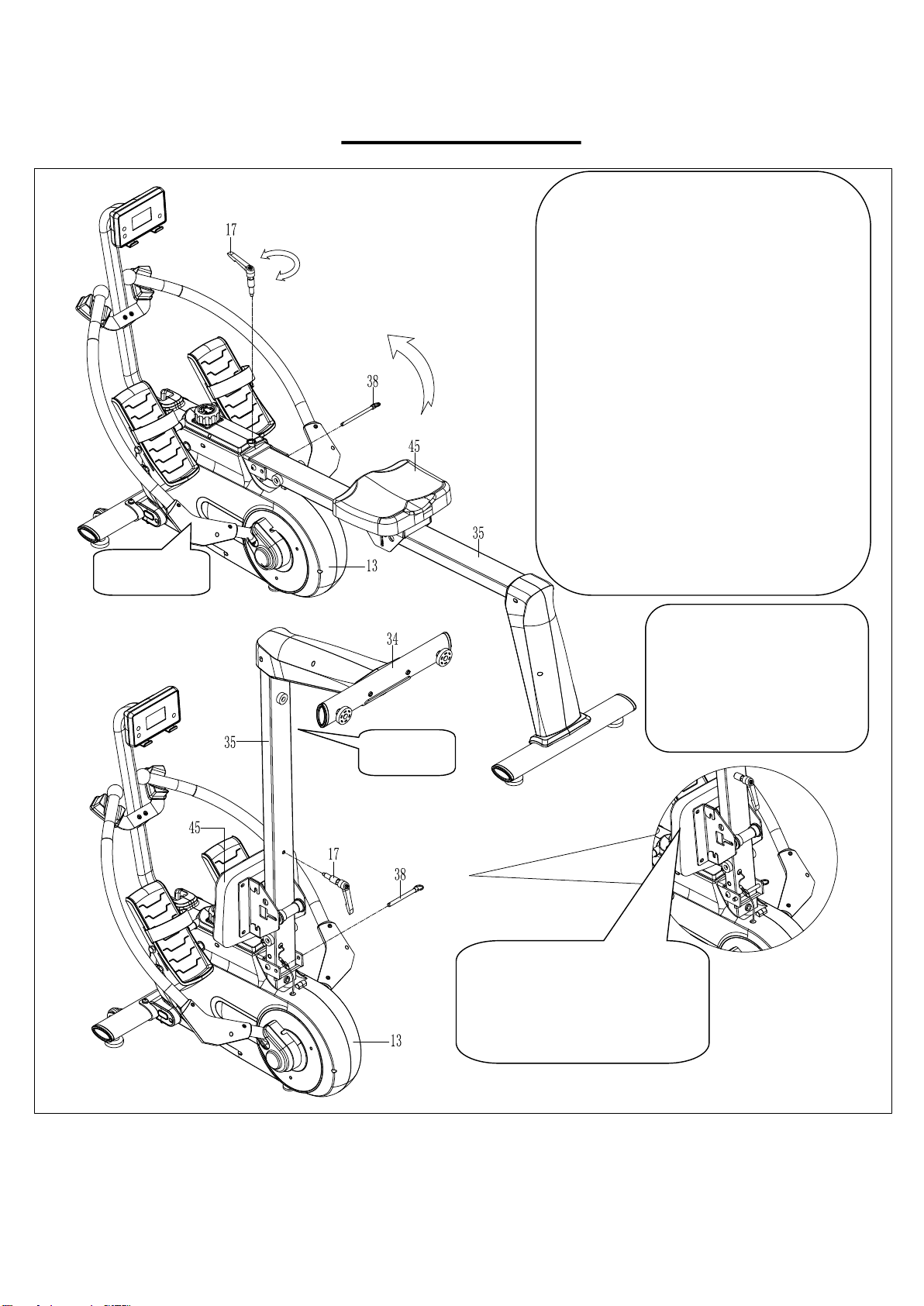
FOLDING GUIDE
When not in use, you can save space
by folding the Sliding Rail (No. 35).
Disassemble L Knob (No. 17) and
pull out Pull Pin (No. 38) from Main
Frame (No. 13). Fold the Sliding Rail
(No. 35) to vertical angle (Figure A).
SAFETY NOTE: The seat will glide
down when folding the Sliding Rail
(No. 35).
Re-insert Pull Pin (No. 38) into the
hole on Main Frame (No. 13), then
tighten L Knob (No. 17) to Sliding
Rail (No. 35) (Figure B).
Figure A
Figure B
ATTENTION!
The Seat (No. 45) will glide
down when folding the
Sliding Rail (No. 35).
Loosen
Tighten
CAUTION!
Use caution when
vertically fold the Sliding
Rail (No. 35) as your
head may touch the
Rear Stabilizer (No. 34)
.

13
EXERCISE COMPUTER
KEY FUNCTIONS:
MODE: Press this button to change the display or to choose a program.
SET: In the setting mode, press this button to increase the setting value
for TIME, COUNT, and CAL.
RESET:
1. In setting mode, press this button to reset the value for TIME, COUNT, and CAL.
2. In monitor mode, hold this button for 3 seconds to reset all values to zero.
FUNCTIONS:
SCAN: Press MODE until “SCAN” appears, the computer will rotate through all the 4 functions: Time,
Count, Cal, Total Count. Each display will be held for 6 seconds.
COUNT (CNT): Displays an instant count with a range from 0 ~ 9999 COUNT. The count value can
be set in advance, when it approaches the preset count, the computer will beep for 10 seconds.
TIME: Counts the total time from exercise start to the end with a range from 0:00 ~ 99:59 M. Exercise
time can be set in advance, when it approaches the preset time, the computer will beep for 10
seconds. The maximum preset time is 99 minutes.
CALORIES (CAL): Counts the total calories burned from exercise start to the end with a range from
0.0 ~ 9999CAL. The calorie value can be set in advance, when it approaches the preset calorie, the
computer will beep for 10 seconds.
TOTAL COUNT (TOTAL): Displays the total count from the first use. The range is from 0 ~ 9999
COUNT.
AUTO ON/OFF & AUTO START/STOP: When there is no signal of exercise or operation for 4
minutes, the power will turn off automatically. Once motion begins, the computer will turn on
automatically.
OPERATION:
SET: Press MODE to choose the display window that needs to be pre-set. Press SET to increase the
value to reach your desired time, calorie, or count. Hold SET to increase the value. Press RESET to
reset values.
BATTERY: When the display screen light begins to fade, remove the batteries and replace with 2 pcs
SIZE AAA, UM4, R03.
Version 3.1
S E T
R E S E T
M O D E