1
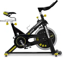
PURE DESIGN
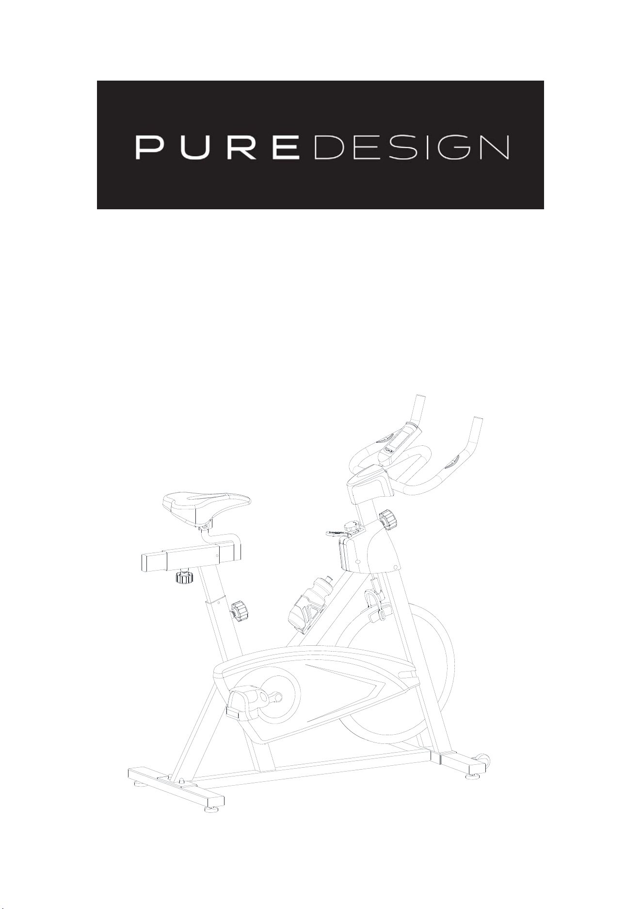
SPINNING BIKE
OWNER’S MANUAL
SB4 V2

2
Dear Customer,
Please read this instruction very carefully before using this item. You
will find important information regarding safety of your spinner bike.
Note the following precaution before assembling or
operating the machine.
1、 Keep children and pets away from the Spinning Bike at all times.
DO NOT leave unattended children in the same room with the
machine.
2、 Handicapped or disabled persons should not use the
Spinning Bike without the presence of a qualified health professional of
a qualified health professional or physician.
3、 If the user experiences dizziness, nausea, chest pain, or any
other abnormal symptoms, STOP the workout at once. CONSULT A
PHYSICIAN IMMEDIATELY.
4、 Before beginning training, remove all within a radius of 2 meters from the
machine. DO NOT place any sharp objects around the Spinning Bike.
5、 Position the Spinning Bike on a clear, level surface away from
water and moisture. Place mat under the unit to help keep the
machine stable and to protect flooring.
6、 Use the Spinning Bike only for its intended use as described in this
manual. DO NOT use any other accessories not recommended by
the manufacturer.
7、 Assemble the machine exactly as the descriptions in the
instruction manual.
8、 Check all bolts and other connections before using the
machine for the first time and ensure that the trainer is in the safe
condition.

3
9、 Hold a routine inspection of the equipment. Pay special
attention to components which are the most susceptible to wear off, i.e.
connecting points and wheels. The defective components should be
replaced immediately. The safety level of this equipment can only be
maintained by doing so. Please don't use the Spinning Bike until it is
repaired well.
10、 NEVER operate the Spinning Bike if it is not functioning properly.
11、 This machine can be used for only one person’s training at a
time.
12、 Do not use abrasive cleaning articles to clean the machine.
Remove drops of sweat from the machine immediately after finishing
training.
13、 Always wear appropriate workout clothing when exercising.
Running or aerobic shoes are also required.
14、 Before exercising, always do stretching first.
15、 The power of the machine increases with increasing the
speed, and the reverse. The machine is equipped with adjustable
knob, which can adjust the resistance.
WARNING: BEFORE BEGINNING THIS OR ANY EXERCISE
PROGRAM, CONSULT YOUR PHYSICIAN F I R S T. THIS IS
ESPECIALLY IMPORTANT FOR INDIVIDUALS OVER THE AGE
OF 35 OR PERSONS WITH PRE-EXISTING HEALTH
PROBLEMS. READ ALL INSTRUCTIONS BEFORE USING THE
SPINNING BIKE . THANE ASSUMES NO RESPONSIBILITY FOR
PERSONAL INJURY OR PROPERTY DAMAGE SUSTA I N E D
BY OR THROUGH THE USE OF THIS PRODUCT
4
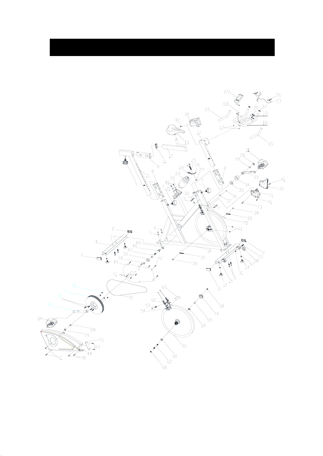
EXPLODED-VIEW & PARTS LIST:

5
NO NAME QUANTITY SPEC
1 PEDAL 1
JD-301
(
9/16"
)
2 END CAP1 5 60*30*1.5
3 CARRIAGE BOLT 4 GB/T 12-1988 M8*42
4 REAR STABILIZER 1 WELDING
5 FLAT WASHER 1 4 GB/T 95-2002 8
6 DOMED NUT 4
GB/T 802-1988 M8
(H=16mm)
7
SPRING ADJUSTMENT
KNOB
3 φ57*62 (M16*1.5)
8 PLASTIC SLEEVE 3
INNER 53.5*23.5*1.5
OUTER 60*30*1.5
9 CHAIN WHEEL 1 φ200*24
10 VERTICAL SEAT POST 1 WELDING
11 END CAP2 1
配
53.5*23.5*1.5
管
12 SEAT POST 1 WELDING
13 SEAT 1 DD-2681
14 STOPPER 4 φ55*40/(M8)
15 FRONT STABILIZER 1 WELDING
16 MAIN FRAME 1 WELDING
17 HANDLEBAR POST 1 WELDING
18 HANDLE BAR 1 WELDING
19 ELASTIC WASHER 4 GB/T 859-1987 8
20 BOLT 4
GB/T 70.2-2000
M8*15
21 FLAT WASHER 2 2 GB/T 95-2002 6
22 B0TTLE HOLDER 1 117*85*90
23 B0TTLE 1 XS-003(1#)
24 BRAKE KNOB 1 112*32*7
25 ADJUSTMENT KNOB 1 φ58*74
26 LITTLE PLASTIC RING 1 14*8*9
27 PLASTIC RING 1 φ20*φ9*3
28 FIXING NUT 1 2
GB/T 6177.2-2000
M10*1.25
29 CRANK END CAP 2 φ23*7.5
30 BOLT 2 4 M8*15
31 LOCK NUT 7 GB/T 889.1-2000 M8
32 CHAIN WEEL 1 170*27
33 LEFT CRANK 1 170*27
34 CRANK COVER 1 φ45*28
35 BEARING 2 6203ZZ
36 DOMED NUT 1 GB/T 802-1988 M6

6
37 U BRACKET 1 δ2.5
38 FIXING NUT 2 2
GB/T 6177.2-2000
M10*1.0
39 FIXING BOLT 2 M6*55
40 NUT 2 GB/T 41-2000 M6
41 SCREW 1 9 ST4.2X19
42 SCREW 2 5 GB/T 845-1985 ST4.2*19
43 SCREW 3 2 GB/845-85 ST4.2X9.5
44 OUTER CHAIN COVER 1 738*320*52 (660g)
45 LITTLE CHAIN COVER 1 91.6*21.4*2 (5g)
46 AXIS 1 φ20*137
47 LONG FIXING TUBE 1 φ22*φ17.05*36.1
48 SHORT FIXING TUBE 1 φ25*φ20.5*11.5
49 INNER CHAIN COVER 1 515*296*2.5 (350g)
50 BELT 1 5PK
52 BRAKE 1 2PCS 130mm
53 SPECIAL BOLT 1 M6*75
54 BRAKE PLASTIC 2 85*43*13
55 BOLT 2 GB/T 5780-2000 M8*40
56 WHEEL 2 φ50*23
57 NUT 4 GB/T 41-2000 M8
58 FIXING NUT 2 2 M10*1.0 (H=5.0mm)
59 FIXING TUBE 1 φ13.6*φ10.3*35
60 BEARING 2 6000ZZ
61 FLYWHEEL 1 φ453*27 (17.5KG)
62 FLYWHEEL SHAFT 1 φ10*147
63 WOOLLY BLOCK 2 85*40*6
64 END CAP 2 φ25*1.5
65 FOAM GRIP 2 φ23*φ29*465
66 FIXING NUT 1 φ28*M20*1
67 END CAP 3 φ14*14
68 COMPUTER HOLDER 1 WELDING
69 COMPUTER 1 HS-6023
70 HANDLEBAR COVER 1 115*89*75
71 RIGHT PROTECT COVER 1 156*80*174
72 LEFT PROTECT COVER 1 157*73*157
73 SCREW 4 1 ST2.9*9.5
74 FLYWHEEL COVER 1 φ59*35
75 SERSOR 1 SR-202
76
PULSE SENSOR
2 LT16
77 PULSE SENSING LINE 1
L=600
,
2lines
78 SCREW 5 2
GB/T 15856.1-2002
ST4.2X13
7
FIG.1
ASSEMBLY INSTRUCTION:
1.PREPARATION:
A. Before assembling make sure that you will have enough space around the item.
B. Use the present tooling for assembling.
C. Before assembling please check whether all needed parts are available (at the above
of this instruction sheet you will find an explosion drawing with all single parts (marked
with numbers) which this item consists of.
2.ASSEMBLY INSTRUCTION:
:
FIG.2
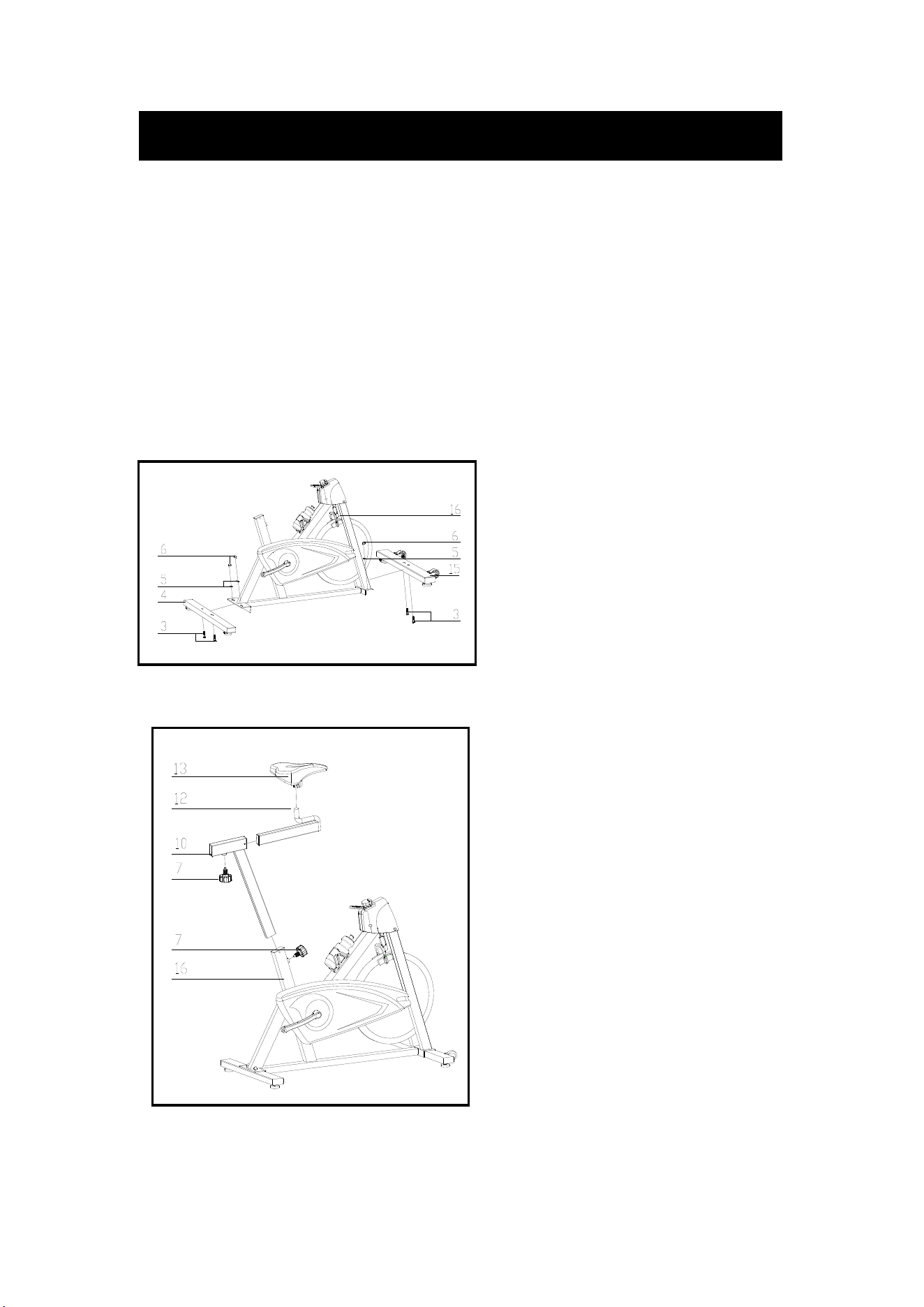
FIG.2:
Slide the Vertical Seat Post (pt.10)
into the seat post housing on the main
frame (pt.16). Then slide the Seat
Post (pt.12) into the Vertical Seat Post
(pt.10). You will have to slacken the
knurled section of the Spring
Adjustment Knob (pt.7) ,then pull the
knob back and then select and align
holes for the desired height. Release
the knob and retighten the knurled
portion.
Now fix the Seat (pt.13) to the Vertical
Seat Post (pt.12) as shown, and
tighten the bolts around the screws
under the seat.
FIG.1:
Attach the Front Stabilizer (pt.15) to the
Main Frame (pt.16) using two sets of
Ø8 Flat Washer (pt.5), M8 Domed Nut
(pt.6) and M8*55 Carriage Bolt (pt.3).
Attach the Rear Stabilizer (pt.4) to the
Main Frame (pt.16) using two sets of
Ø8 Flat Washer (pt.5), M8 Domed Nut
(pt.6) and M8*65 Carriage Bolt (pt.3).
8
`
FIG.3
FIG.4
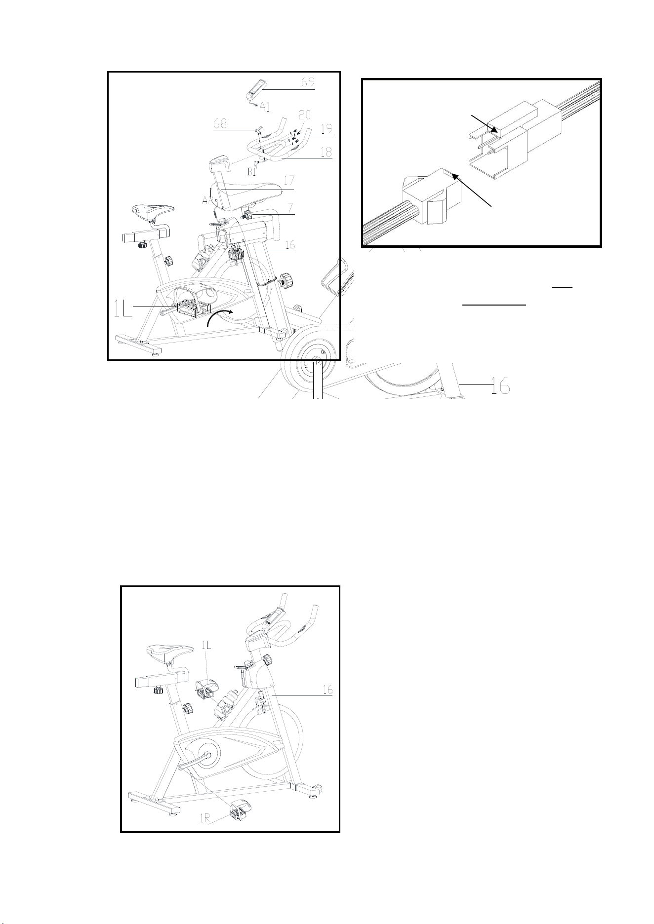
FIG.3:
Slide the Handlebar Post (pt.17) into the handlebar post housing on the main frame. You
will have to slacken the knurled section of the Spring Adjustment Knob (pt.7) and pull the
knob back and then select and align holes for the desired height. Release the knob and
retighten the knurled portion.Then fix the Handlebar (pt.18) with four Bolt (pt.20) and four
Elastic Washers(pt.19).
Finally put the Computer(pt.73) to the Computer Holder(pt.68)
ATTENTION: YOU SHOULD FIX THE HANDLEBAR TIGHTLY
FIG.4:
The Pedals (pt.1 L & pt.1 R) are marked
"L" and "R" - Left and Right.
Connect them to their appropriate crank
arms. The right crank arm is on the
right- hand side of the cycle as you sit
on it.
Note that the Right pedal should be
threaded on clockwise and the Left
pedal anticlockwise.
ATTENTION::
Connected with the computer line, to Gap
(A1)
corresponding to the convex point
(A2) to insert
link
Gap
A1
Convex point
A2
FIG.3-1
9
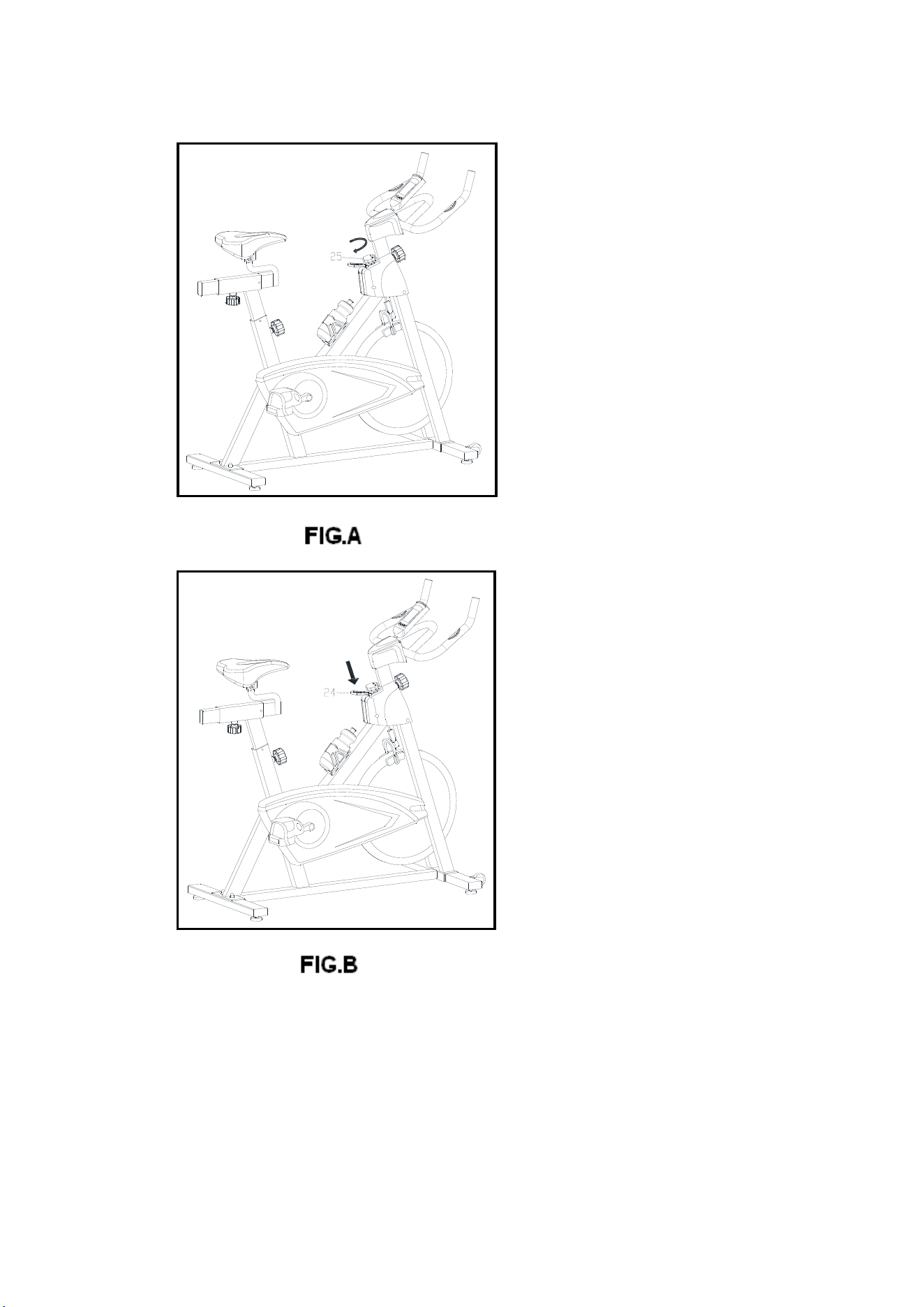
A.) Adjusting the Tension:
Increasing or decreasing the
tension allows you to add variety
to your workout sessions by
adjusting the resistance level of
the bike. To increase tension and
increase resistance (requiring
more strength to pedal), turn the
Tension Control Knob (pt.
25
) to
the right.
To decrease tension and
decrease resistance (requiring
less strength to pedla), turn the
Tension Control Knob (pt.
25
) to
the left.
B.) Using the Emergency Brake:
Use this safety feature in any
situation where you would need to
get off the bike and/or
stop the bike’s flywheel.
To use the Emergency Brake
function in any situation you would
need it in, firmly press downon the
Emergency Brake (pt.24).

10
ADJUSTMENT
*To adjust the seat height, slacken the spring knob on the vertical post
stem on the main frame and pull back the knob. Position the vertical
seat post for the desired height so that holes are aligned, then release
the knob and retighten it.
*To move the seat forward in the direction of the handlebar or
backwards away from it, loosen the adjusting knob and washer and
pull the knob back. Slide horizontal seat post into desired position.
Align holes and then retighten the adjusting knob.
*To adjust the handlebar height, slacken the spring knob and pull both
knobs back. Slide the handlebar post along the housing on the main
frame to the desired height and, with the holes aligned correctly,
tighten the spring adjusting knob.
11
EXERCISE INSTRUCTIONS
Using your SPINNING BIKE provides you with several benefits, it will improve
your physical fitness, tone muscle and in conjunction with calorie controlled diet help
you lose weight.
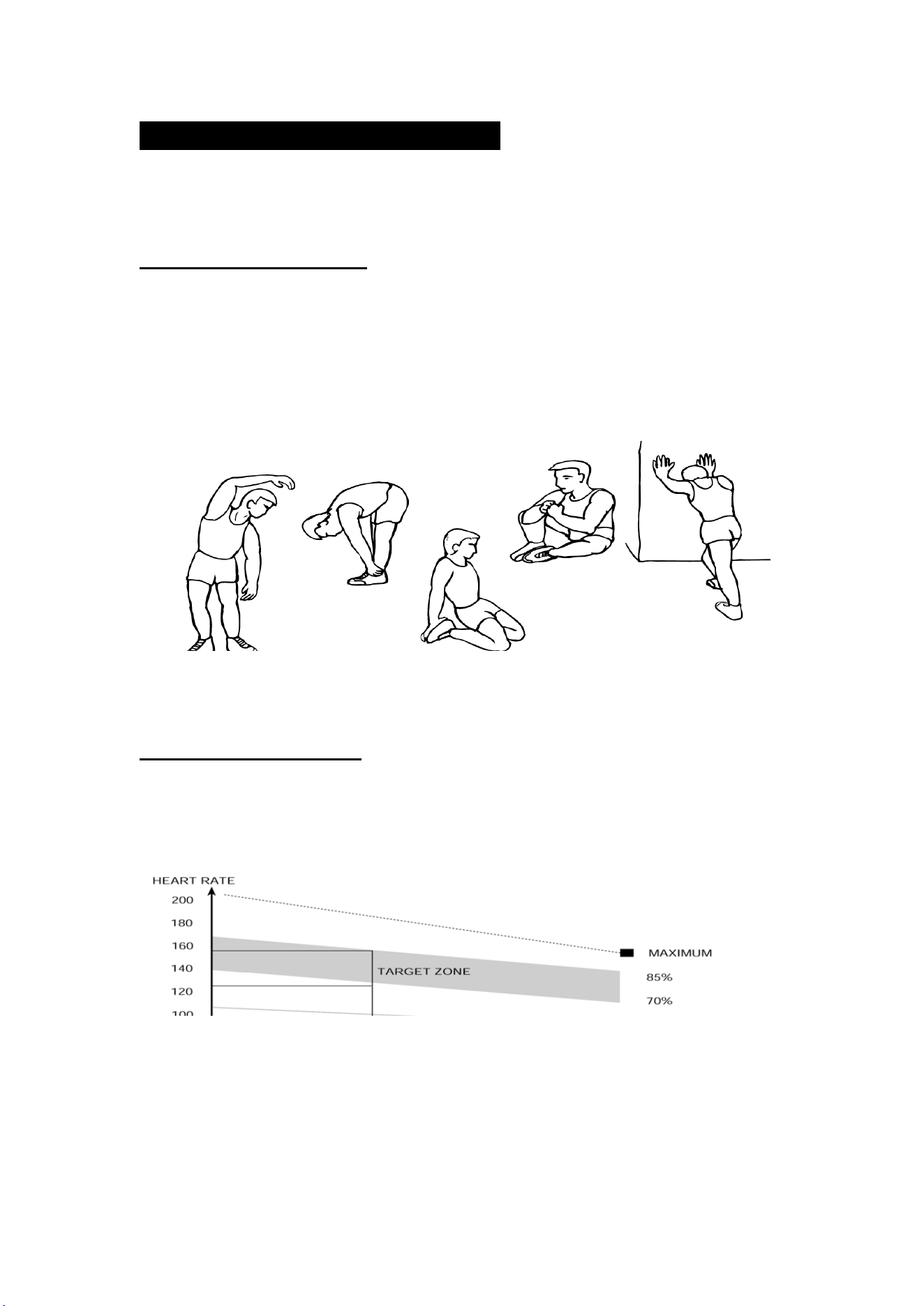
1.The Warm Up Phase
This stage helps get the blood flowing around the body and the muscles
working properly. It will also reduce the risk of cramp and muscle injury. It is advisable
to do a few stretching exercises as shown below. Each stretch should be held for
approximately 30 seconds, do not force or jerk your muscles into a stretch - if it hurts,
STOP.
2.The Exercise Phase
This is the stage where you put the effort in. After regular use , the muscles in
your legs will become Stronger. Work to your but it is very important to maintain a
steady tempo throughout. The rate of work should be sufficient to raise your heart
beat into the target zone shown on the graph below.
This stage is to let your Cardio-vascular System and muscles wind down. This is a
repeat of the warm up exercise e.g. reduce your tempo, continue for approximately 5
minutes. The stretching exercises should now be repeated, again remembering not to
force or jerk your muscles into the stretch.
SIDE BENDS OUTER THIGH
INNER THIGH
FORWARD
BENDS
CALF / ACHILLES
This stage should last for a minimum of 12 minutes for most people

12
As you get fitter you may need to train longer and harder. It is advisable to train at
least three times a week, and if possible space your workouts evenly throughout the
week.
MUSCLE TONING
To tone muscle while on your SPINNING BIKE you will need to have the
resistance set quite high. This will put more strain on our leg muscles and may mean
you cannot train for as long as you would like. If you are also trying to improve your
fitness you need to alter your training program. You should train as normal during the
warm up and cool down phases, but towards the end of the exercise phase you
should increase resistance, making your legs work harden than normal. You may
have to reduce your speed to keep your heart rate in the target zone.
WEIGHT LOSS
The important factor here is the amount of effort you put in. The harder and
longer you work the more calories you will burn. Effectively this is the same as if you
were training to improve your fitness, the difference is the goal.
USE
The tension control knob allows you to alter the resistance of the pedals. A high
resistance makes it more difficult to pedal, a low resistance makes it easier. For the
best results set the tension while the bike is in use.

13
RD-93212 TMONITOR INSTRUCTION:
一.FUNCTION BUTTONS
MODE
a) Press the button to select TIME, DISTANCE, CAL and PULSE to preset.
SET
a)To set up the target value of TIME, DISTANCE, CAL and PULSE.
b)Hold down the button to speed up the increment.
RESET
a)Press the button to reset function value when setting .
b)Press the button and hold for 2 seconds to reset all value to be zero.
(When the user replace batteries, all the values will reset to ZERO automatically.)
二.FUNCTIONS & OPERATIONS
1. Time
Accumulates total time from 00:00 up to 99:59.The user may preset target time by
pressing SET button .Each increment is 1 minute. Automatically count down from
targeting value during exercise.
2. Speed
Display the current training speed from 0.0 to 999.9 KPH or MPH.
3. Distance
Accumulates total distance from 0.0 up to 999.9 km or mile. The user may preset target
distance by pressing SET button. Automatically count down from targeting value during
exercise.
4. Calories
Accumulates calories consumption during training from 0 to max.999.9 calories. The user
may also preset the target calorie before training by press SET & MODE button.
Automatically count down from targeting value during exercise.
三.Note:
1) If the computer displays abnormally, please re-install the battery and try again.
2) The batteries must be removed from the appliance before it is scrapped and that they
are disposed of safely.
3) While the user starts to do exercise, the Display will show out the workout value
automatically. Once they stop exercising over 256 sec. the Display will turn off.

14
WaterRower
72 South Street Rydalmere NSW 2116