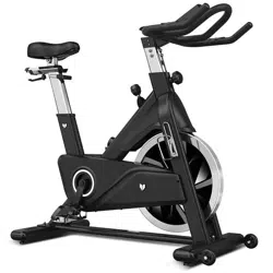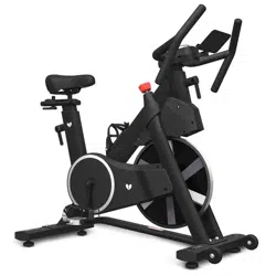
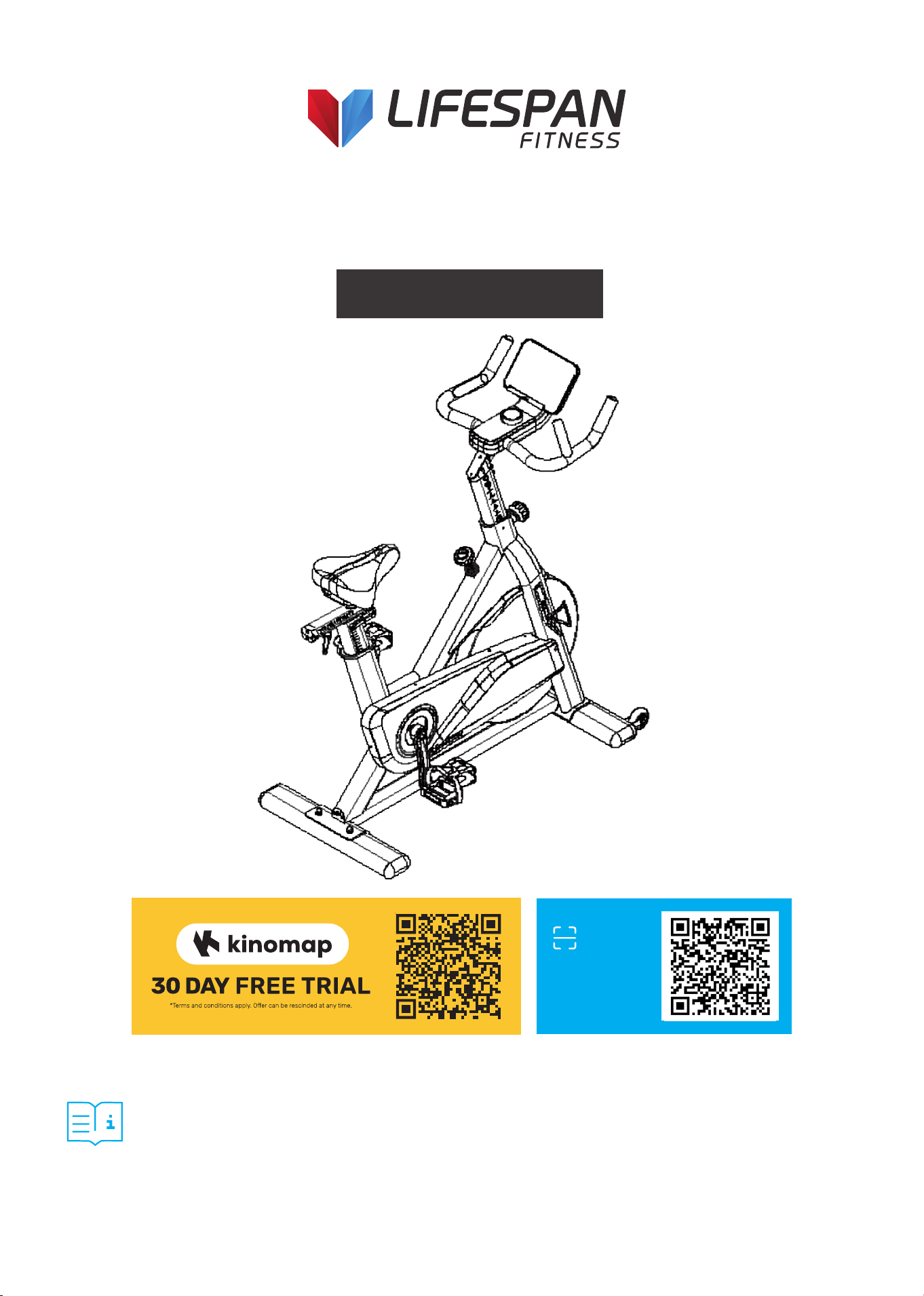
SM-810 Commercial
Spin Bike
USER MANUAL
Product may vary slightly from the item pictured due to model upgrades.
Read all instructions carefully before using this product.
Retain this owner’s manual for future reference.
NOTE:
This manual should not be used to guide your purchasing decision. Your product, and the contents inside its carton, may vary
from what is listed in this manual. This manual may also be subject to updates or changes. Updated manuals are available
through our website at www.lifespanfitness.com.au
Find the
Digital Manual
Online

2
TABLE OF
CONTENTS
I. Important Safety Instructions . . . . . . . . . . . . . . . . . . . . . . . . . . . . . . . 03
II. Care Instructions . . . . . . . . . . . . . . . . . . . . . . . . . . . . . . . . . . . . . . . . . . . . . 04
III. Exploded Diagram . . . . . . . . . . . . . . . . . . . . . . . . . . . . . . . . . . . . . . . . . . . . 05
IV. Parts List . . . . . . . . . . . . . . . . . . . . . . . . . . . . . . . . . . . . . . . . . . . . . . . . . . . . . . 06
V. Assembly Instructions . . . . . . . . . . . . . . . . . . . . . . . . . . . . . . . . . . . . . . . . 09
VI. Operation Guide . . . . . . . . . . . . . . . . . . . . . . . . . . . . . . . . . . . . . . . . . . . . . . 14
VII. Exercise Guide . . . . . . . . . . . . . . . . . . . . . . . . . . . . . . . . . . . . . . . . . . . . . . . . 19
VIII. Warranty . . . . . . . . . . . . . . . . . . . . . . . . . . . . . . . . . . . . . . . . . . . . . . . . . . . . . . 21
| TABLE OF CONTENTS

3IMPORTANT SAFETY INSTRUCTIONS |
I. IMPORTANT SAFETY
INSTRUCTIONS
WARNING: Read all instructions before using this machine.
It is important your machine receives regular maintenance to prolong its useful life. Failing to
regularly maintain your machine may void your warranty.
Please always keep this manual with you.
• It is important to read this entire manual before assembling and using the equipment. Safe and
effective use can only be achieved if the equipment is assembled, maintained, and used properly.
PLEASE NOTE: It is your responsibility to ensure that all users of the equipment are informed of all
warnings and precautions
• Before starting any exercise program, you should consult your doctor to determine if you have any
medical or physical conditions that could put your health and safety at risk, or prevent you from
using the equipment properly. Your doctor’s advice is essential if you are taking medication that
affects your heart rate, blood pressure or cholesterol level.
• Be aware of your body’s signals. Incorrect or excessive exercise can damage your health. Stop
exercising if you experience any of the following symptoms: pain, tightness in your chest, irregular
heartbeat, and extreme shortness of breath, lightheadedness, dizziness, or feelings of nausea. If you
do experience any of these symptoms, you should consult your doctor before continuing with your
exercise program.
• Keep children and pets away from the equipment. This equipment is designed for adult use only.
• Use the equipment on a solid, flat level surface with a protective cover for your floor or carpet.
To ensure safety, the equipment should have at least 2 meters of free space around it.
• Before using the equipment, check that the nuts and bolts are securely tightened. If you hear any
unusual noises coming from the equipment during use and assembly, stop immediately. Do not use
the equipment until the problem has been rectified.
• Wear suitable clothing while using the equipment. Avoid wearing loose clothing that may get caught
vin the equipment or that may restrict or prevent movement.
• This equipment is designed for indoor and family use only.
• Care must be taken when lifting or moving the equipment so as not to injure your back.

4
• Always keep this instruction manual and assembly tools at hand for reference.
• The equipment is not suitable for therapeutic use.
• The pulse or heart rate sensors are not medical devices. Various factors, including the user’s
movement, may affect the accuracy of heart rate readings. The pulse sensors are intended only as
exercise aids in determining heart rate trends in general.
| CARE INSTRUCTIONS
II. CARE INSTRUCTIONS
IMPORTANT
a. All nuts and bolts are to be checked and tightened on a regular basis. This includes pedals and other
moving parts. Failure to do so may cause damage to your threads and void your warranty.
b. Lubricate moving joints after periods of usage.
c. Be careful not to damage plastic or metal parts of the machine with heavy or sharp objects.
d. The machine can be kept clean by wiping it down using dry cloth.
Power Adapter Information
Input: 100-240V 50/60Hz
Output: 9V 1000mA
5EXPLODED DIAGRAM |
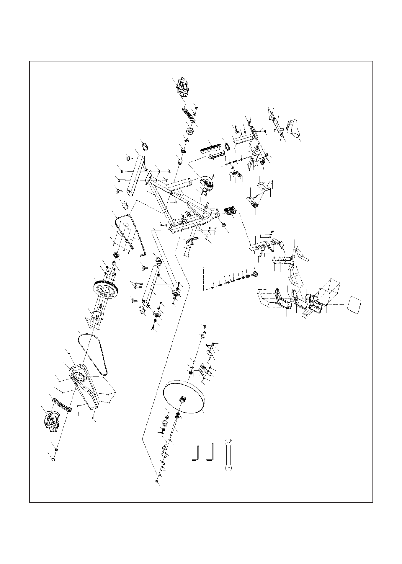
III. EXPLODED DIAGRAM
120
74
118
119
75
122
70
116
117
73
78
81
60
03
07
67
82
79
17
67
79
82
82
67
73
79
96
98
101
41
43
57
09
18
97
65
88
123
45
76
15
110
59
10
100
100 59
59
36
35
68
19
06
99
59
95
20
19
68
68
25
24
22
26
13
55
93
70
23
68
77
21
68
99
59
80
68
37
05
92
94
33
113
53
111
29
49
32
54
54
79
16
76
107L
114
12
105
62
62
105
114
91
77
69
56
82
42
30
63
115
71
90
71
71
34
107R
53
113
71
71
69
49
31
01
58
61
109
56
72
104
102
70
69
105
62
105
114
11
56
51
111
51
64
56
51
111
51
64
44
77
69
70
79
106
103
52
89
85
87 50
66
60
78
14
04
108
08
108
83
28
27
121
50
38
85
02
79
66
52
84
48
39
48
86
S15 S13
40
47
46
Inner Hexagon
Spanner (5#)
Inner Hexagon
Spanner (6#)

6 | PARTS LIST
IV. PARTS LIST
No. Description Specs Qty
1 Main Frame Weldment 1
2 Belt Board Assembly Weldment 1
3 Handlebar Weldment 1
4
Connecting Plate
Assembly
Weldment 1
5 Vertical Seat Post Weldment 1
6
Connecting Bar
Assembly
Weldment 1
7
Handlebar
Connection Assembly
Weldment 1
8 Magnetic Holder Weldment 1
9 Brake Pole Weldment 1
10 Seat Post Weldment 1
11 Front Stabilizer Weldment 1
12 Rear Stabilizer Weldment 1
13 Adjustment Buckle Weldment 1
14 Motor Cable Holder δ2 1
15
Motor Cover
Assembly
Weldment 1
16 Power Fixing Plate δ2 1
17 Handlebar Post 80*40*2.5 1
18 Compression Spring Φ1.5*66.5 1
19 Aluminum Handle 80*16*10 2
20 Long Shaft Ф5*56 1
21 Step Shaft Ф8*50.5 1
22 Spacer Ф8*Ф5.2*20 1
23 Fixed Shaft Ф8*16 1
24 Short Shaft Ф5*23 1
25 Fixing Frame 65*27.5*23.5 1
26 Little Spring φ8Xφ0.8X50 1
No. Description Specs Qty
27 Magnet 30*15*10 6
28 Flywheel
20KG*Φ460*46
*89*5PK
1
29 Fixing Nut M25*1 1
30 Crank Axle φ25*182 1
31 Metal Tube φ30*φ25.05*9 1
32 Inner Metal Tube
φ30*φ25.05
*56.1
1
33 Left Crank 170*42.5 1
34 Right Crank 170*42.5 1
35 Nut Block Φ25*10.5 1
36 Little Spring φ1X11.5 1
37 L Knob M10*20 1
38 Flywheel Shaft
Φ17*155*3*
89*M12*1.25
1
39 Pressure Pulley φ43*28 1
40 Wrench 132*28/33*t6 1
41
Little Compression
Spring
φ1.0X55 1
42 Belt Pulley φ200*24 1
43 Adjustment Nut 1
44 Bottle Holder φ6 1
45 Electronic Line L=235MM 1
46
6# Hexagonal
Wrench
6 mm 1
47
5# Hexagonal
Wrench
5 mm 1
48 Bearing 6001ZZ 6001ZZ 2
49 Bearing 6005ZZ 6005ZZ 2
50 Bearing 6203RS 6203RS 3
51 Bearing 608ZZ 608ZZ 4

7PARTS LIST |
No. Description Specs Qty
52 Hex Flange Nut M12X1.25 2
53 Little Hex Flange Nut M12X1.25 2
54 Cap Nut M8 4
55 Lock Nut M5 M5 1
56 Lock Nut M8 M8 7
57 Lock Nut M10 M10 1
58 Hex Nut M8 1
59
Hex Socket Head
Screw M4*8
M4*8 6
60
Hex Socket Head
Screw M6*10
M6*10 3
60
Hex Socket Head
Screw M6*12
M6*12 4
61
Hex Socket Head
Screw M8*45
M8*45 1
62 Carriage Bolt M8X62 4
63
Hex Socket
Countersunk Head
Screw
M8*18 4
64 Hex Head Bolt M8*40 2
65
Internal Hex Socket
Head Screw M6*10
M6*10 2
66
Internal Hex Socket
Head Screw M8*10
M8*10 2
67
Internal Hex socket
Head Screw M8*15
M8*15 6
68
Phillips Countersunk
Head Screw
M5*12 12
69
Cross Self-drilling
and Self-tapping
Screw
ST4.2X19 6
70
Phillips Pan Head
Self-tapping Screw
ST2.9*9.5
ST2.9*9.5 9
No. Description Specs Qty
71
Phillips Pan Head
Self-tapping Screw
ST4.2X9.5
ST4.2X9.5 7
72
Phillips Pan Head
Self-tapping Screw
ST4.2*19
ST4.2*19 2
73
Phillips Pan Head
Self-tapping Screw
ST4.2*16
ST4.2*16 9
74
Phillips Countersunk
Head Self-tapping
Screw
STA.2x9.5 4
75
Phillips Pan Head
Screw M4*12
M4*12 4
76
Phillips Pan Head
Screw M5*10
M5*10 4
77 Flat Washer 5 5 5
78 Flat Washer 6 6 7
79 Flat Washer 8 8 12
80 Large Washer 10 1
81 Elastic Washer 6 6 4
82 Elastic Washer 8 8 10
83 Retaining Ring Φ10 Φ10 1
84 Retaining Ring Φ12 Φ12 1
85 Retaining Ring Φ17 Φ12 2
86 Waveform Washer 12
d1=12 D=16
s=0.3
1
87 Waveform Washer 17
d1=17 D=23
s=0.3
1
88 Retaining Ring 3 3 1
89 Fixed Plate δ2.5 2
90 Outer Chain Cover 756*283*71 1
91 Inner Chain Cover 743*277*17 1
92 Upper Cover 115*56*12.5 1
93 Front Bushing 257*48*46 1

8
No. Description Specs Qty
94 Rear Bushing 332*65*46 1
95
U-shaped Handle
Cover
70*58*20 1
96 Brake Knob M10*100 1
97 Square Spacer 20.6*20.6*16 1
98 Flexible Tube φ40.6*60 1
99
Lower Rail
Decorative Cover
19*59.5*23 2
100
Upper Rail
Decorative Cover
19*59*25 2
101
Brake Positioning
Sleeve
25*25*27 1
102 Left Flywheel Cover 212*139.5*58 1
103 Bushing 80*40 1
104 Plastic Strip 30*79*4 1
105 Stopper φ52*43, M8X25 4
106 Adjustment Knob
φ60*80
(M16*1.5)
1
107 Pedal
JD-037V 9/16"-
SPD
1
108 Small Bushing φ18*φ10*10 2
No. Description Specs Qty
109 Plastic Plug φ14*14 1
110 Saddle C-3604 1
111
Flywheel Installation
Cover
φ59*35 1
112 Wheel φ69X26 2
113 Crank Cap φ28*6.5 2
114 Oval Plug 100*50*2 4
115 Belt
5PK53.5INCH,
L=1360mm
1
116
Computer Upper
Cover
319*100*126 1
117
Computer Lower
Cover
319*100*140 1
118 Upper IPAD Holder 215*155*5 1
119 Lower IPAD Holder 220*160*41.7 1
120 EVA Pad T1*212.8*152.9 1
121 Woolly Block 30*17*12MM 1
122 Display 1
123 Wire Pulling Motor 1
| PARTS LIST
9ASSEMBLY INSTRUCTIONS |
V. ASSEMBLY INSTRUCTIONS
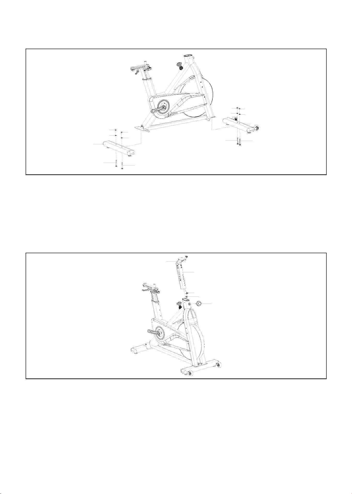
A. Attached the Front Stabilizer (pt.11) to the Main Frame (pt.1), Lock the Front Stabilizer on the Main
frame with 2pcs of Carriage Bolts (pt.62) and 2pcs of Flat Washers (pt.79) and 2pcs of Domed Nut
(pt.54).
B. Use the same way to lock the Rear Stabilizer (pt.12) on the Main frame.
Please make sure you lock the Front stabilizer and Rear Stabilizer firmly on the Main Frame.
STEP 1: Assemble Front and Rear Stabilizers
FIG 1
54
54
79
79
12
62
62
54
54
79
79
11
62
62
A. Unscrew the Adjustment knob (pt.106), connect the line B in the Handlebar connection assembly
(pt.07) to the line A in the main frame (pt.1), and insert the Handlebar connection assembly (pt.07) into
the main frame, and lock the Adjustment knob (pt.106).
NOTE: The Adjustment knob (pt.106) needs to be aligned with the hole of the Handlebar connection
assembly (pt.07) and tightened clockwise.
STEP 2: Assemble Handlebar Connection
FIG 2
07
17
B
A
106
10 | ASSEMBLY INSTRUCTIONS
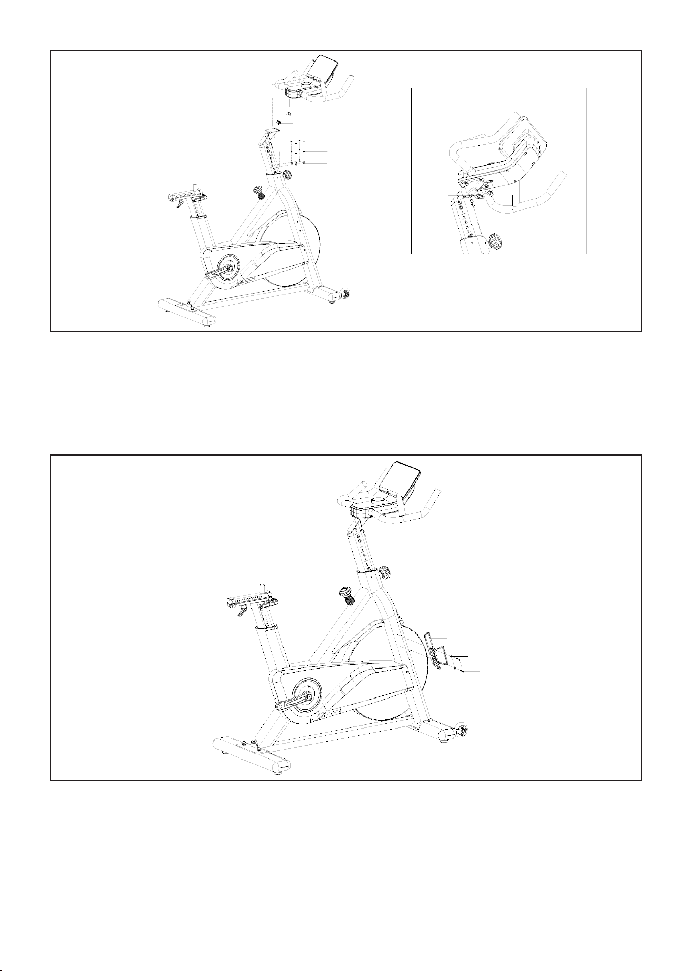
A. Use tool 5# Hexagonal wrench (pt.47) to secure Flat Washer 6 (pt.78) 4PCS, Elastic washer 6 (pt.81)
4PCS, and Hex socket head screw M6*12 (pt.60) 4PCS to connect the Handlebar (pt.3) to the Handlebar
connection assembly (pt.07), as shown in FIG.3.
B. Connect line A and line B together.
STEP 3: Assemble Handlebar
FIG 3
A
B
78
81
60
B
A
A. Lock the Bottle holder (pt.44) on the main frame with Cross self-drilling and self-tapping screw (pt.69)
2pcs and Flat Washer 5 (pt.77) 2pcs.
STEP 4: Assemble Bottle Holder
FIG 4
44
77
69
11ASSEMBLY INSTRUCTIONS |
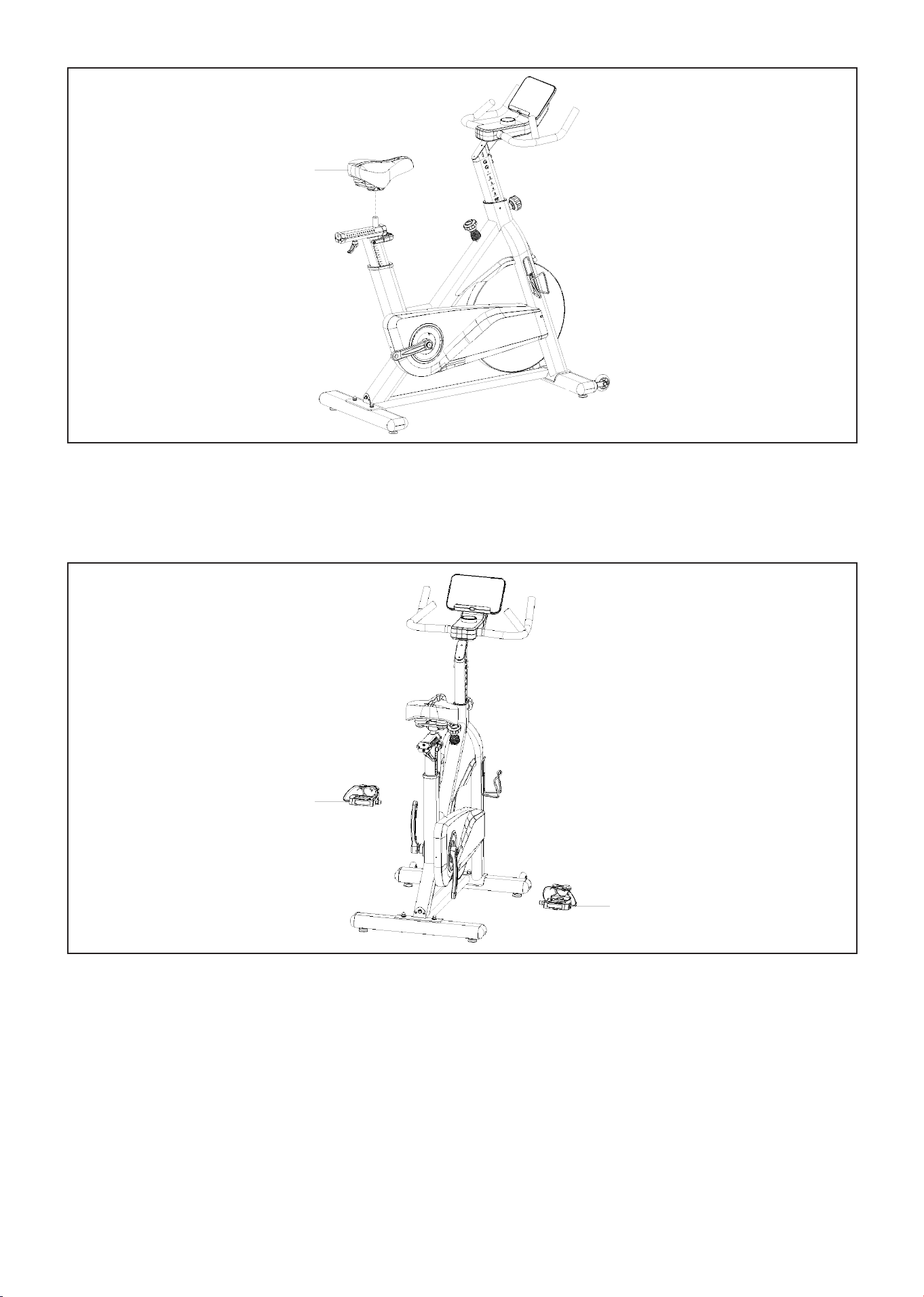
A. Place the Saddle (pt.110) horizontally, as shown in FIG.5, use 2x Wrench (pt.40) to tighten the nuts on
both sides at the same time. Do not tighten the nut on one side only as this will not fully secure seat.
STEP 5: Assemble Saddle
FIG 5
110
Caution: Installing the pedals on the wrong side, tightening it the wrong way, or not fully tightening
before use will strip the thread on the cranks and pedals. Read instructions carefully.
A. As shown in the picture on the, install the pedals (pt.107R) with right-side crank and tighten it
clockwise.
B. Install the left pedal (pt. 107L) on the left side crack and tighten it counterclockwise.
C. Use the tool Wrench (pt.40) to fully tighten it, ensure it is threaded all the way.
STEP 6: Assemble Peddle
FIG 6
107L
107R
12 | ASSEMBLY INSTRUCTIONS
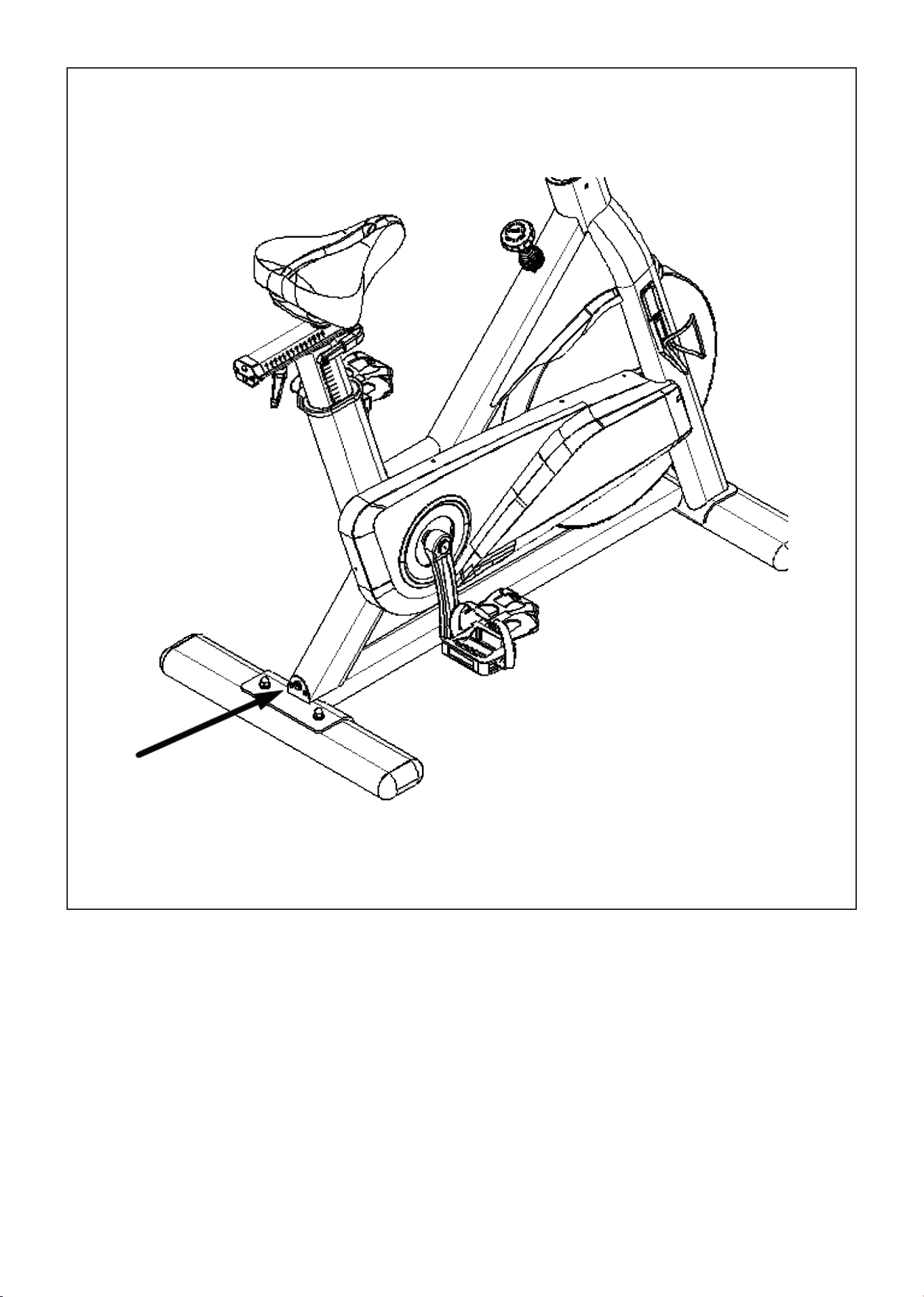
The equipment is now fully set up and you can now plug it into power.
The plug socket is located at the back of the machine, on the bottom section (refer to image).
STEP 7: Plug to Power
FIG 6

13ASSEMBLY INSTRUCTIONS |
SEAT & HANDLEBAR ADJUSTMENT
UP/DOWN
To adjust the seat height, hold onto the seat and pull the seat post up to your desired height.
To lower it you will need to pull the release lever underneath the seat up and while holding the lever,
push the seat down, then release the lever to lock into position.
CAUTION: We recommend to not sit on the seat when pulling up the release lever up as the added
weight can jam the release lever
FORWARD/BACKWARD
The Adjusting lever under the seat acts like a wrench.
To loosen:
Loosen the adjusting handle under the seat by turning it fully to the left side then pull the lever down
and move it back to the right side. Let go of the lever so it slots back into the bolt and then turn to the
left again. Continue doing this until the bolt is loosen enough for you to move your seat.
To tighten:
Once you have set the position you want, tighten by pulling the lever down and move it to the left side.
Release the lever until it clicks to the bolt and then turn the lever to the right.
Repeat by going back to the left side until the seat is fully locked into place.
HANDLEBAR ADJUSTMENT
To adjust the handlebar height, slacken the spring knob and pull it back. Slide the handlebar post along
the housing on the main frame to the desired height and, with the holes aligned correctly, tighten the
spring adjusting knob.
EMERGENCY STOP
On the machine frame there is an emergency knob. Push down on the knob to stop the pedaling motion.

14
VI. OPERATION GUIDE
| OPERATION GUIDE
1.1 DISPLAY FUNCTIONS
Item No. Items Display Description
1 Full View
1. Display Resistance levels (Levels 1-32)
2. Display work out data "SPEED", "TIME", "DISTANCE",
"CALORIE"
3. Display Bluetooth status
2 Scan Mode
On scan mode the data will show:
1. Small window for resistance level
2. SPEED, TIME, DISTANCE and CALORIE will appear on
the main window and will change in rotation.
3. Bluetooth status indicator
3 Lock Mode
To lock a data you wish to view (rather then SCAN
MODE), press down on the knob display to the data you
wish to view - SPEED, TIME, DISTANCE, CALORIE.
On the small window, the resistance level is shown.
4 E01 Code
Purpose: To prevent assembly errors and damage to the
entire electronic component set caused by extremely
rare abnormal parts, an E01 detection mechanism for
the cable motor is added.
Issue: The shuttle cannot properly recognize the
motor’s rotation state. Possible reasons include:
1. Check whether the motor wire rope is stuck and if
the motor resets normally after power-on.
2. Verify if the wire is loose or if the wire plug is skewed.
3. Ensure that the motor pulling force is sufficient at
the extreme position to prevent failure to reset to
1st gear normally. To verify, immediately adjust to the
middle gear after power-on to check for any recurring
errors.
4. Shuttle components may be damaged, though this is
highly improbable.
5. Cable could be damaged.
15OPERATION GUIDE |
1.2 DISPLAY INSTRUCTIONS
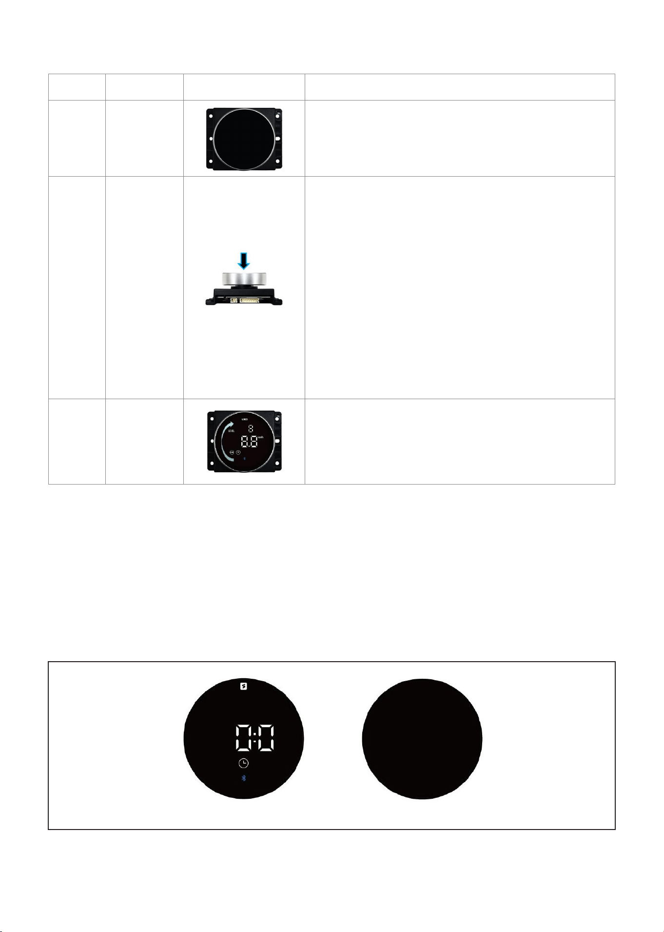
Item No. Items Display Description
1
Awaken
Device
1. In sleep mode, the display is off.
2. The knob will turn on either upon being pressed or
upon detecting any motion.
2
Press
Knob
1. The knob display enters sleep mode after 3 minutes
of inactivity.
2. Press the knob to turn on the device from sleep
mode.
3. Press the knob to initiate the device in wake-up
mode.
4. Press the knob to switch display modes during
exercise.
5. Long-press the knob for 2 seconds to reset data and
transition to wake-up mode.
6. A buzzing sound accompanies pressing the knob.
3
Rotate
Knob
1. Rotate the knob clockwise to increase resistance.
2. Rotate the knob anticlockwise to decrease
resistance.
3. There is a buzzing sound when the knob is rotated.
1.3 DETAILED OPERATING INSTRUCTIONS
Upon powering on the knob display, the BUZZER will emit a long beep, the knob display will illuminate,
and the device will enter the READY state (as depicted in Figure 1). Additionally, after power-on, the
resistance will automatically reset to the "1" gear. If there is no operation within 1 minute, the device will
initiate an automatic reset, clearing the data.
Furthermore, in the absence of any operation for 3 minutes, the display will completely turn off,
transitioning into standby mode (as illustrated in Figure 2).
Fig 1 Fig 2
16 | OPERATION GUIDE
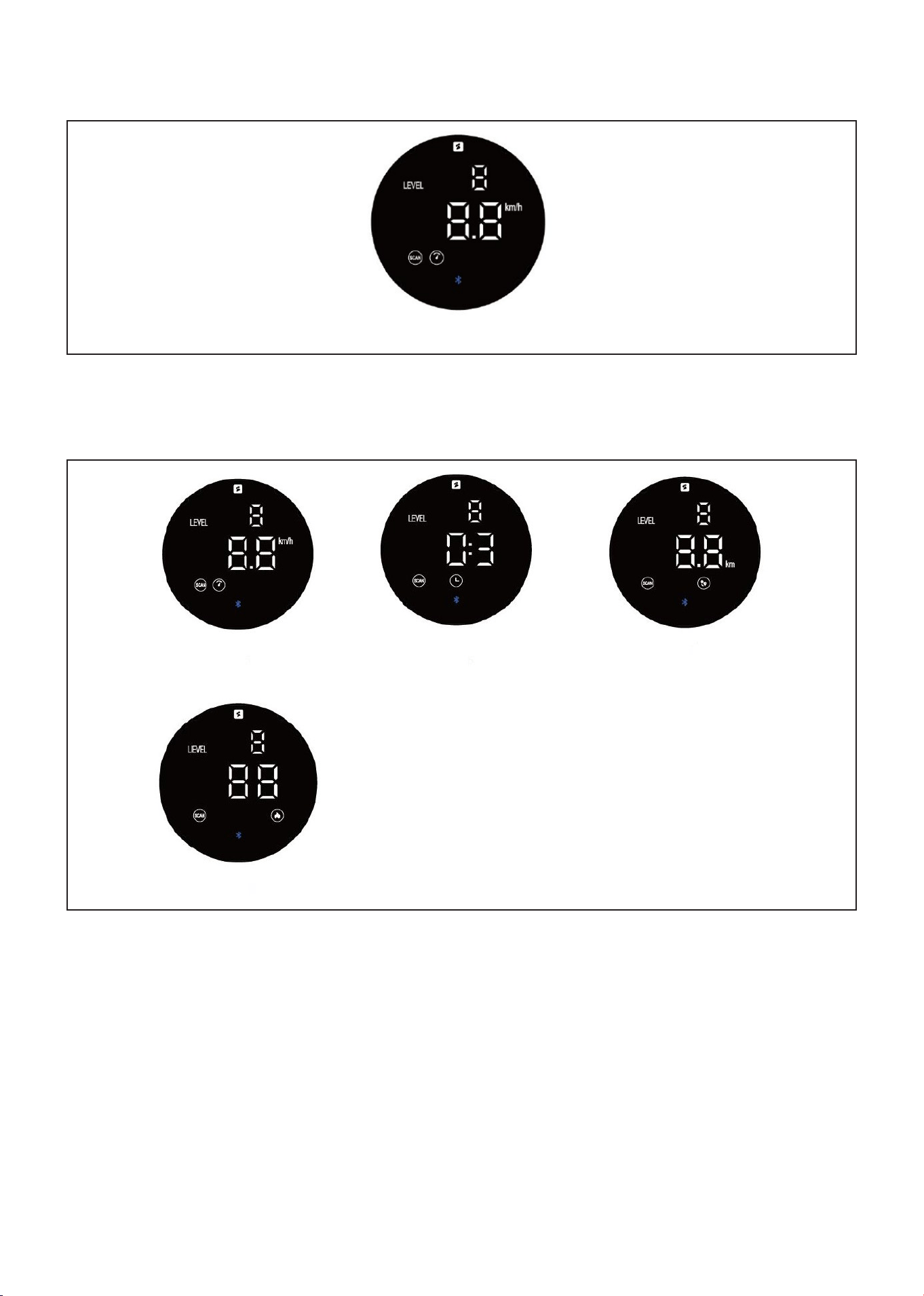
While in the READY state, press the knob or commence pedaling to access the exercise mode. The small
window will display "LEVEL" every 3 seconds (as depicted in Figure 3).
Fig 3
The main window numbers are initially set to a carousel display featuring the illuminated "SCAN" icon.
The display cycles through "Speed," "Time," "Distance," and "Calories" every 3 seconds, as illustrated in
Figure 5, Figure 6, Figure 7, and Figure 8.
Fig 5 Fig 6 Fig 7
Fig 8
Pressing the knob allows you to switch the display mode to lock mode. In this mode, the "SCAN" icon is
not shown, and the display remains fixed, showing one of the following data: "Speed," "Time," "Distance,"
or "Calories," as depicted in Figure 9, Figure 10, Figure 11, and Figure 12.
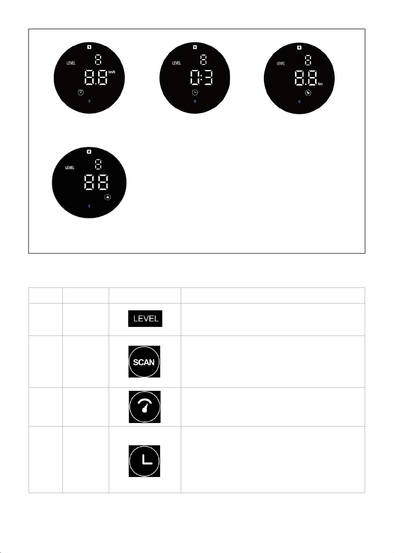
17OPERATION GUIDE |
Fig 9 Fig 10 Fig 11
Fig 12
1.4 DISPLAY ICON DESCRIPTIONS
Item No. Items Display Description
1
Resistance
Level
1 ~ 32
The higher the level, the greater the resistance
2 SCAN
If Selected: Indicates that the data is in carousel
mode.
If Not Selected: Indicates that the data is in lock mode
of the Data you are viewing.
3 Speed
0.0 ~ 99.9 km/h
60 RPM - 21.5 kilometers/hour.
4 Time
0:0 ~ 99:5
In wake-up mode, timing commences with a quick
press of the knob or upon detecting movement, and
the timing ceases 4 seconds after movement comes to
a halt.

18 | OPERATION GUIDE
Item No. Items Display Description
5 Distance 0.0 ~ 999 km
6 Calories
0.0~999kcal
There is a direct proportional relationship with the
resistance level. For instance, Resistance 1 corresponds
to 11.4 kcal/kilometer, whereas Resistance 32 corre-
sponds to 44.6 kcal/kilometer.
7
Bluetooth
Icon
If Displayed: Bluetooth is connected.
If Not Displayed: Bluetooth is not connected.
19
VII. EXERCISE GUIDE
PLEASE NOTE:
Before beginning any exercise program, consult your physician. This is important especially if you are
over the age of 45 or individuals with pre-existing health problems.
The pulse sensors are not medical devices. Various factors, including the user’s movement, may
affect the accuracy of heart rate readings. The pulse sensors are intended only as an exercise aid in
determining heart rate trends in general.
Exercising is great way to control your weight, improving your fitness and reduce the effect of aging and
stress. The key to success is to make exercise a regular and enjoyable part of your everyday life.
The condition of your heart and lungs and how efficient they are in delivering oxygen via your blood to
your muscles is an important factor to your fitness. Your muscles use this oxygen to provide enough
energy for daily activity. This is called aerobic activity. When you are fit, your heart will not have to work
so hard. It will pump a lot fewer times per minute, reducing the wear and tear of your heart.
So as you can see, the fitter you are, the healthier and greater you will feel.
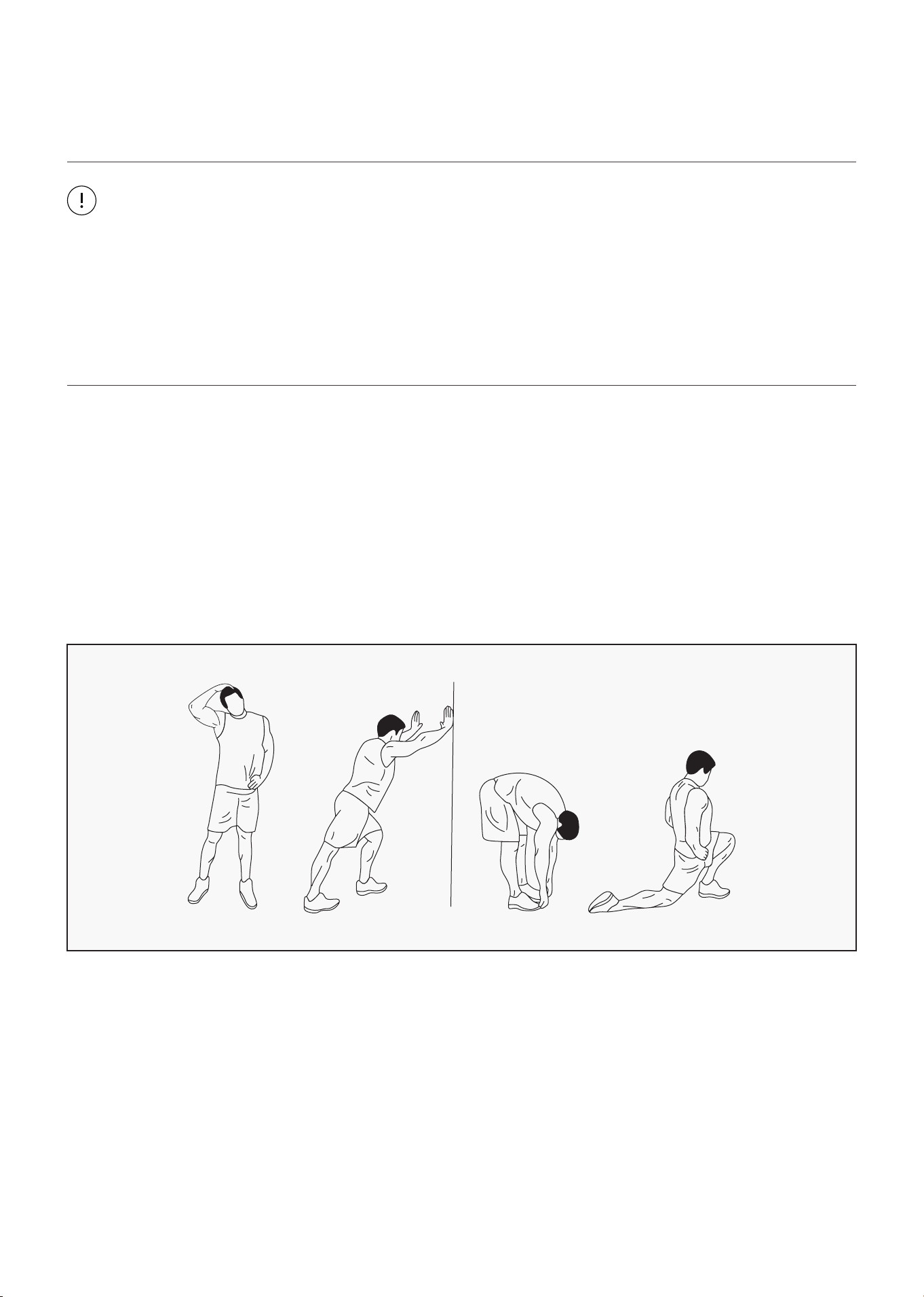
WARM UP
Start each workout with 5 to 10 minutes of stretching and some light exercises. A proper warm-up
increases your body temperature, heart rate and circulation in preparation for exercise. Ease into your
exercise.
After warming up, increase the intensity to your desired exercise program. Be sure to maintain your
intensity for maximum performance. Breathe regularly and deeply as you exercise.
EXERCISE GUIDE |
20
COOL DOWN
Finish each workout with a light jog or walk for at least 1 minute. Then complete 5 to 10 minutes of
stretching to cool down. This will increase the flexibility of your muscles and will help prevent post-
exercise problems.
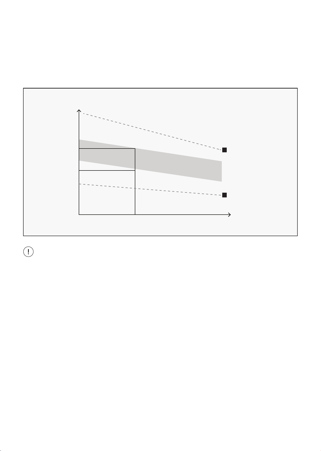
WORKOUT GUIDELINES
This is how your pulse should behave during general fitness exercise. Remember to warm up and
cool down for a few minutes.
TARGET ZONE
MAXIMUM
85%
70%
COOL DOWN
AGE
HEART RATE
200
180
160
140
120
100
80
20 25 30 35 40 45 50 55 60 65 70 75
| EXERCISE GUIDE

21
VIII. WARRANTY
AUSTRALIAN CONSUMER LAW
Many of our products come with a guarantee or warranty from the manufacturer. In addition, they come
with guarantees that cannot be excluded under the Australian Consumer Law. You are entitled to a
replacement or refund for a major failure and compensation for any other reasonably foreseeable loss
or damage.
You are entitled to have the goods repaired or replaced if the goods fail to be of acceptable quality and
the failure does not amount to a major failure. Full details of your consumer rights may be found at
www.consumerlaw.gov.au.
Please visit our website to view our full warranty terms and conditions:
http://www.lifespanfitness.com.au/warranty-repairs
WARRANTY AND SUPPORT
Any claim against this warranty must be made through your original place of purchase.
Proof of purchase is required before a warranty claim may be processed.
If you have purchased this product from the Official Lifespan Fitness website, please visit
https://lifespanfitness.com.au/warranty-form
For support outside of warranty, if you wish to purchase replacement parts or request a repair or
service, please visit https://lifespanfitness.com.au/warranty-form and fill in our Repair/Service
Request Form or Parts Purchase Form.
Scan this QR code with your device to go to lifespanfitness.com.au/warranty-form
WARRANTY |


WWW.LIFESPANFITNESS.COM.AU