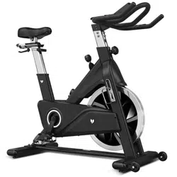
SM-720I Incline/Decline Spin Exercise
Bike with Automatic Magnetic Resistance
USER MANUAL
Product may vary slightly from the item pictured due to model upgrades.
Read all instructions carefully before using this product.
Retain this owner’s manual for future reference.
NOTE:
This manual should not be used to guide your purchasing decision. Your product, and the contents inside its carton, may vary
from what is listed in this manual. This manual may also be subject to updates or changes. Updated manuals are available
through our website at www.lifespanfitness.com.au
Find the
Digital Manual
Online

2
TABLE OF
CONTENTS
| TABLE OF CONTENTS
I. Important Safety Instructions . . . . . . . . . . . . . . . . . . . . . . . . . . . . . . . 03
II. Care Instructions . . . . . . . . . . . . . . . . . . . . . . . . . . . . . . . . . . . . . . . . . . . . . 05
III. Parts List . . . . . . . . . . . . . . . . . . . . . . . . . . . . . . . . . . . . . . . . . . . . . . . . . . . . . 06
IV. Assembly Instructions . . . . . . . . . . . . . . . . . . . . . . . . . . . . . . . . . . . . . . . 07
V. Adjustment Instructions . . . . . . . . . . . . . . . . . . . . . . . . . . . . . . . . . . . . . 12
VI. Emergency Brake Use . . . . . . . . . . . . . . . . . . . . . . . . . . . . . . . . . . . . . . . . . 14
VII. How to Move the Machine . . . . . . . . . . . . . . . . . . . . . . . . . . . . . . . . . . . . 15
VIII. Computer Operation . . . . . . . . . . . . . . . . . . . . . . . . . . . . . . . . . . . . . . . . . . 16
IX. Exercise Guide . . . . . . . . . . . . . . . . . . . . . . . . . . . . . . . . . . . . . . . . . . . . . . . . . 19
X. Warranty . . . . . . . . . . . . . . . . . . . . . . . . . . . . . . . . . . . . . . . . . . . . . . . . . . . . . . . 21

3IMPORTANT SAFETY INSTRUCTIONS |
I. IMPORTANT SAFETY
INSTRUCTIONS
Failure to follow these instructions may lead to personal injury and cause damage to the spin bike.
To reduce the risk of burns, fire, electric shock or injury to any persons, please read the following:
• The maximum user weight is 125kg.
• Do not use the device outdoors.
• The device is intended exclusively for private home use and not for commercial purposes.
• Ensure to turn off from Powerpoint when equipment is not in use.
• The device may only be used for the stated purpose. Improper use is not permitted.
• Never use the device if the power plug is damaged, the device is not working properly or has been
exposed to moisture. In this case, contact your purchase store.
• Do not carry out any changes or maintenance steps on the device that are not described in these
instructions. This can damage the device.
• Make sure that the room in which the device is located is adequately ventilated.
• Elderly or physically disadvantaged people should only use the device under supervision if
intervention by a supervisor is necessary.
• To avoid damaging the device, do not use sprays or aerosol products near the device.
• Keep the device dry and away from moisture and humidity.
• Keep the power plug and the power cord away from hot surfaces.
• Set up the device on a firm, level surface with a sufficient safety perimeter. Make sure that there are
no objects in the immediate vicinity of the device while it is in use, as these may be the cause of
injury.
• Wear comfortable and appropriate clothing during use. Do not use the device wearing just socks or
barefoot. Always wear suitable sportswear. Do not wear clothing or objects that are loose or that could
get caught in the device.
Basic precautions, including the following important safety instructions should always be followed
when using this spinning bike. Read all instructions before using this spin bike. To reduce the risk
of electric shock, always unplug the spin bike from the electrical outlet immediately after using and
before cleaning, assembling, or servicing the spin bike.

4
• Always wear suitable sports shoes. The use of shoes with heels, leather soles or running shoes with
spikes is prohibited.
• CAUTION: Always make sure that your arms and legs as well as (small) children, pets or other objects
are not close to the rear flywheel during operation to avoid possible serious injuries or damage to the
device.
• Never get off the device while the spin bike is inclining or descending.
| IMPORTANT SAFETY INSTRUCTIONS
WARNING:
Consult a doctor before exercising. This note must be observed by the elderly or people with
limited health.
Read all the safety instructions in this manual carefully before using the device.
• The use of the device under the influence of alcohol, drugs or narcotics is strictly prohibited.
• This device must not be used by persons (including children under the age of 14) who have physical
or mental limitations or who do not have sufficient experience to use it.
• Not to be used for medical purposes.
• Place and use the device on a dry, level and non-slip surface with sufficient clearance on all sides.
• Children under 14 years of age must not use the device under any circumstances.
• Keep children under the age of 14 and animals away from the device.
• Pets and children under the age of 14 must keep a safety distance of 3 meters from the device.
Do not leave them unattended near the device.
• Children under the age of 14 should never play in the vicinity of the device or with the device itself.
• Cleaning and maintenance of the device must not be carried out by children under 14 years of age.

5
II. CARE INSTRUCTIONS
IMPORTANT
a. All nuts and bolts are to be checked and tightened on a regular basis. This includes pedals and other
moving parts. Failure to do so may cause damage to your threads and void your warranty.
b. Lubricate moving joints after periods of usage.
c. Be careful not to damage plastic or metal parts of the machine with heavy or sharp objects.
d. The machine can be kept clean by wiping it down using dry cloth.
CARE INSTRUCTIONS |
Power Adapter Information
Input: 100-240V 50/60Hz 3a
Output: 24V 4a
6
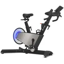
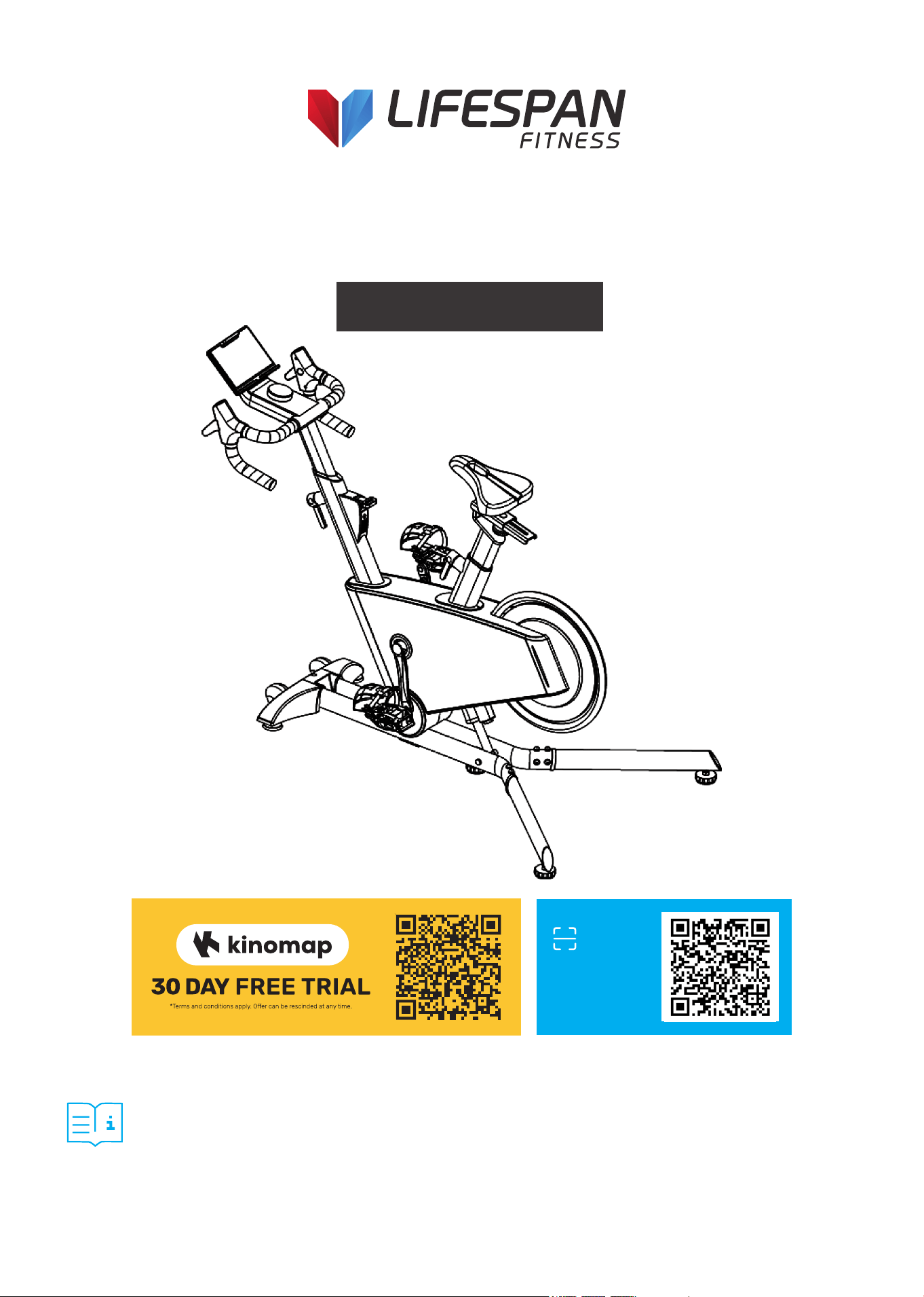
III. PARTS LIST
HARDWARE PACKAGE:
A B C D E
F G C28 C45 C46
C21
| PARTS LIST
D02 E14
MTB110A-BC001
(B17) S5 x 1pc.
(B18) S13-15 x 1pc.
(D24) Ø6
x 4pcs.
(D16) ST3.5*10
x 2pcs.
(D22) Ø8
x 11pcs.
(D10) M8*15 x 8pcs. (D12) M6*12 x 4pcs.
(D26) Ø8 x 11pcs.
(D07) M8*55 x 2pcs. (D28) M8*35 x 1pc. (D08) M5*10 x 1pc.
7
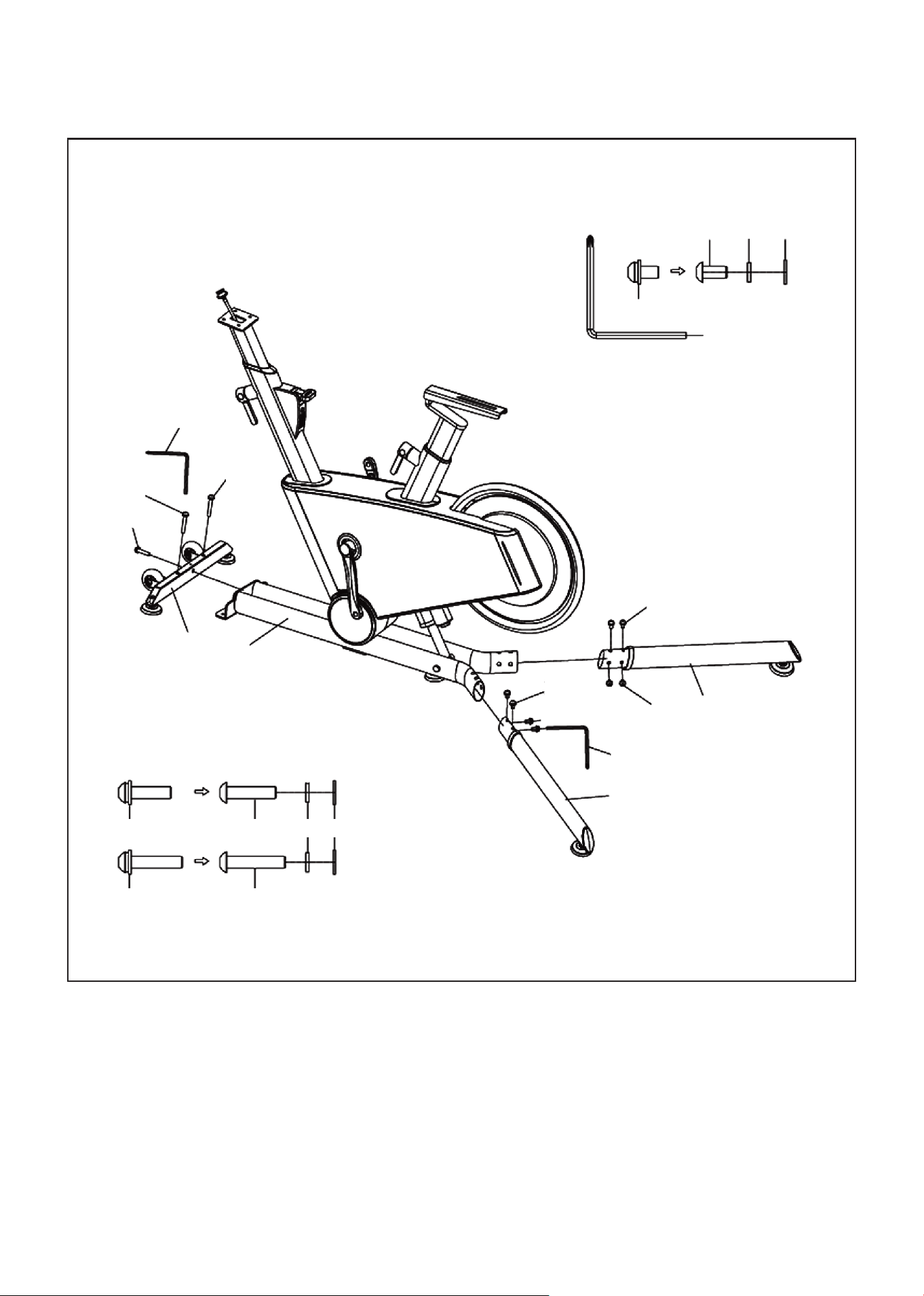
IV. ASSEMBLY INSTRUCTIONS
ASSEMBLY INSTRUCTIONS |
1. Use an Allen wrench (B17) with 3-in-1 screws (D07*2) and 3-in-1 screws (D28*1) to fix the front foot pad
fixing plate group (B) to the main frame assembly (A) and lock it tightly.
2. Install the left rear foot group (C) and right rear foot group (D) on the main frame assembly (A) and
lock it tightly by using an Allen wrench (B17) and three-in-one screw (D10*8).
STEP 1:
B17
D07
D07
D28
B
A
D10
B17
D10
D10
D
C
B17 S5 x 1pc
D10 M8*15 x 8pcs.
D10 D26 D22
D28 M8*35 x 1pc. D28
D26 D22
D07 M8*55 x 2pcs. D07
8 | ASSEMBLY INSTRUCTIONS
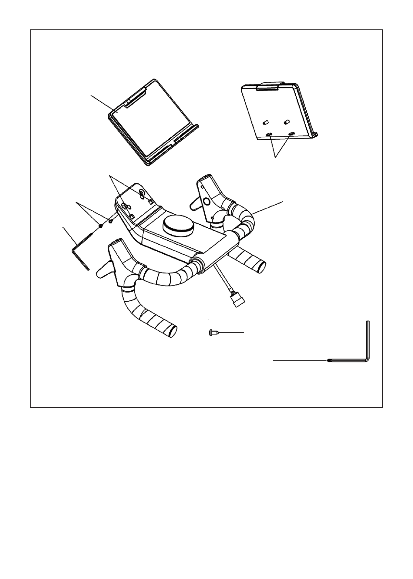
1. First, fasten the buckle (H) on the IPAD holder group (E) into the square hole (K) on the electronic
watch group (F). Then install the IPAD holder group (E) on the electronic watch group (F) with the cross
wrench (B17) and the cross-pan head self-tapping screw (D16).
STEP 2:
D16 ST3.5*10 x 2pcs.
B17 S5 x 1pc.
E
H
K
D16
B17
F
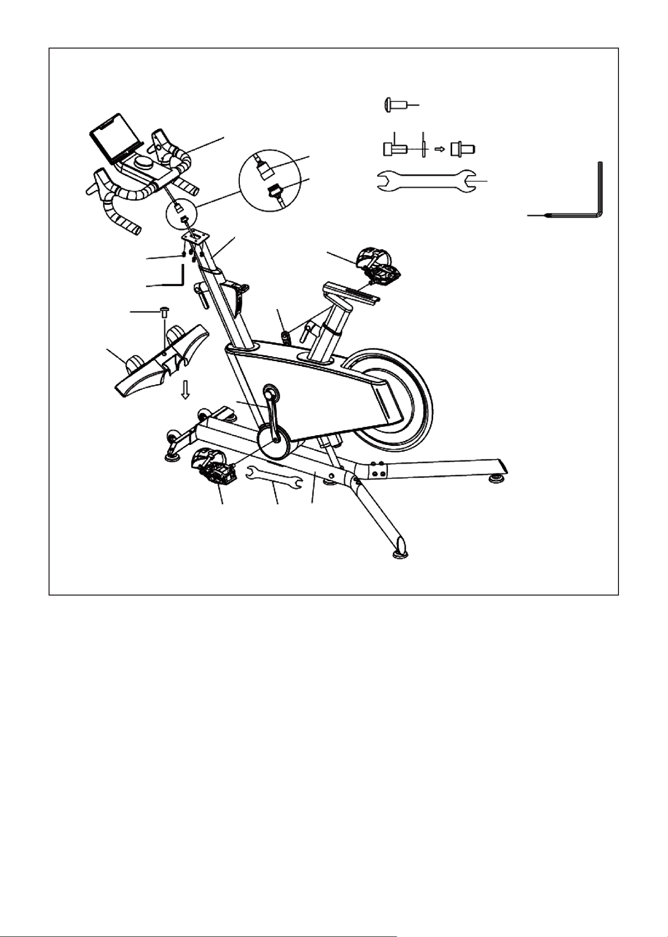
9ASSEMBLY INSTRUCTIONS |
1. Fasten the upper segment line (E09) and lower segment line (E10) as shown in the figure. Then use the
hex wrench (B17) 2-in-1 screw (D12*4) to fix the electronic meter group (F) to the instrument tube
group (A02) and lock it tightly.
CAUTION: Pay special attention not to clip the line!
2. Use a cross wrench (B18) and left pedal (C45) to fix it on the left crank (B01) in counterclockwise turn.
Ensure it is fully tightened.
3. Use a cross wrench (B18) with the right pedal (C46) to fix it on the right crank (B02) in clockwise turn.
Ensure it is fully tightened.
CAUTION: Be careful not to cross thread the pedals and fully tighten before use. On the right side is a
clockwise turn and on the left side is a counterclockwise turn.
4. Fasten the front foot cover (C28) on the main frame assembly (A) and lock it with the cross-pan head
screw (D08), as shown in the figure.
STEP 3:
D08 M5*10 x 1pc.
D12 D24
D12 M6*12 x 4pcs.
B18 S13-15 x 1pc.
B17 S5 x 1pc.
F
E09
E10
A02
D12
B17
D08
C28
B01
B02
C46
C45 B18 A
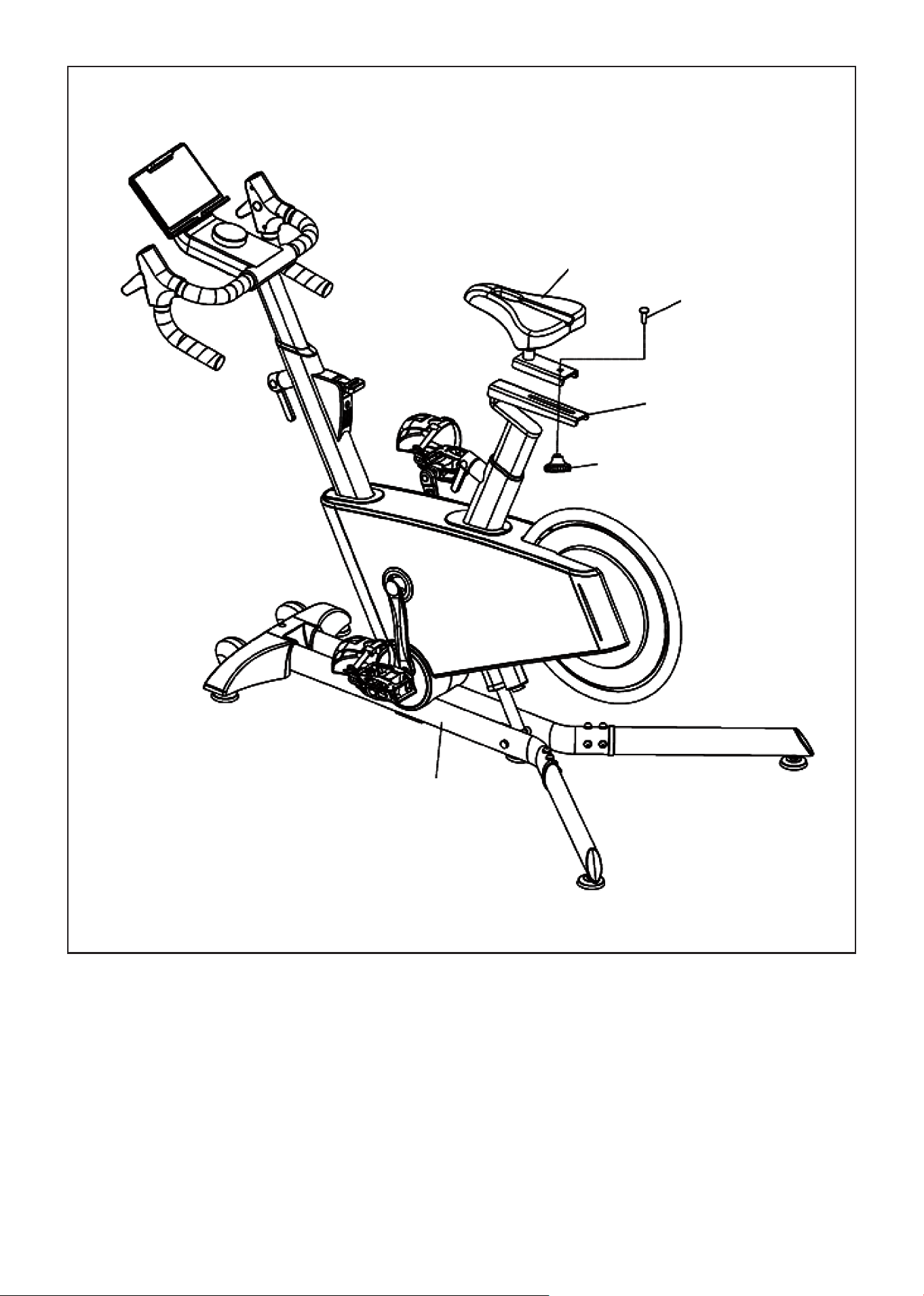
10 | ASSEMBLY INSTRUCTIONS
1. Place the seat pack (G) on the seat pack tube (A03) and use a twist (C21), and square neck bolt (D02)
to secure the seat pack (G) and tighten bolt.
STEP 4:
G
D02
A03
C21
A
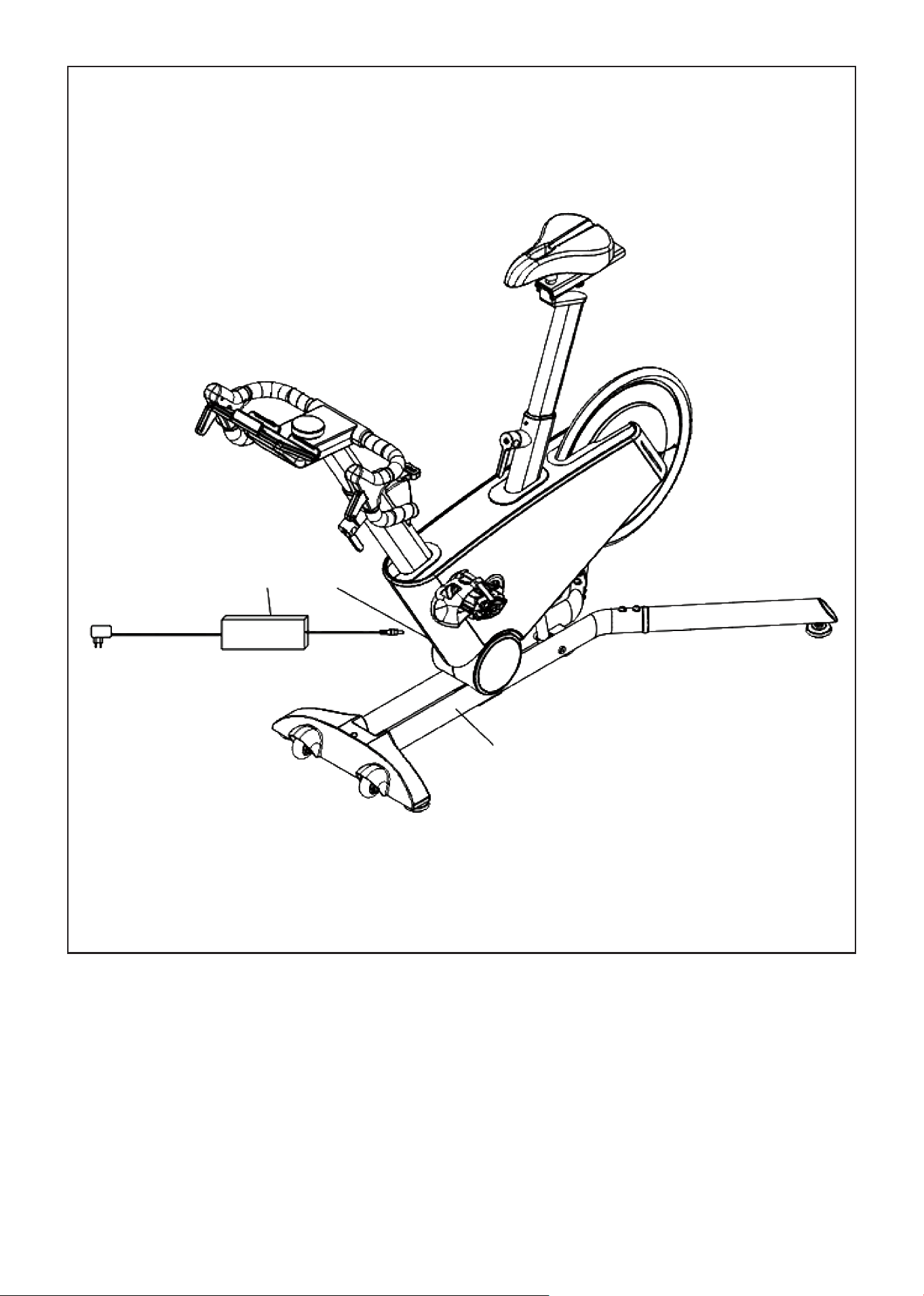
11ASSEMBLY INSTRUCTIONS |
1. Move the stationary bike to the position with power supply, ensure that there is a space distance of
0.6 meters around, and then plug the power adapter (E17) into the power interface (E14) as shown in
the figure.
CAUTION: When powering on the bike it will automatically swing back and forth to calibrate the slope!
STEP 5:
E14E17
A
12
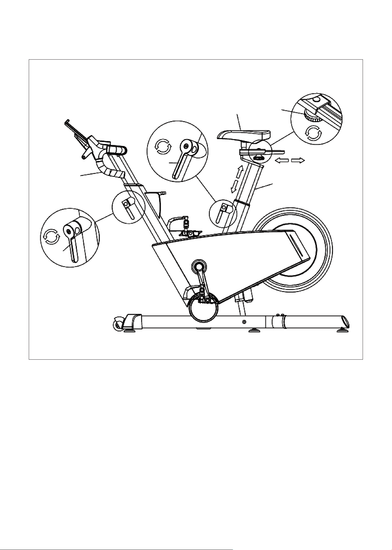
V. ADJUSTMENT INSTRUCTIONS
| ADJUSTMENT INSTRUCTIONS
1. To adjust the height of tube group (A02)/seat cushion tube group (A03), first loosen the L-shaped
elastic pin assembly (B12) by rotating it counterclockwise, and then rotate it clockwise to lock it.
When operating, face the L-shaped elastic pin assembly (B12) to distinguish the direction.
2. Use seat cushion small twist (C21), first turn counterclockwise to loosen, then adjust the seat cushion
sliding assembly (G), after adjustment, turn clockwise to lock.
SEAT HEIGHT
A02
B12
B12
G C21
A03
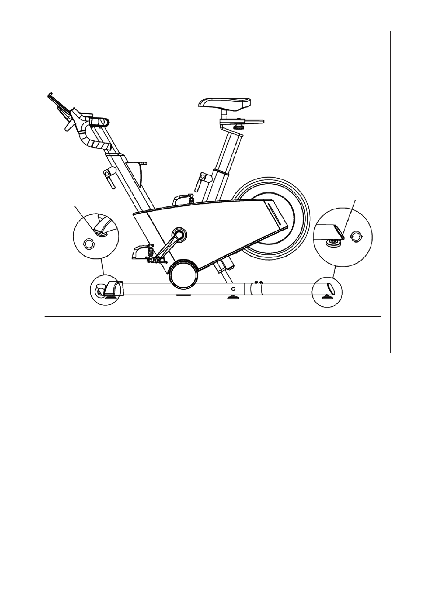
13ADJUSTMENT INSTRUCTIONS |
1. When the machine shakes due to uneven floor, adjust the adjustable foot mat (C29) counterclockwise
or clockwise until they touch the ground evenly.
FLOOR LEVELERS
C29
C29
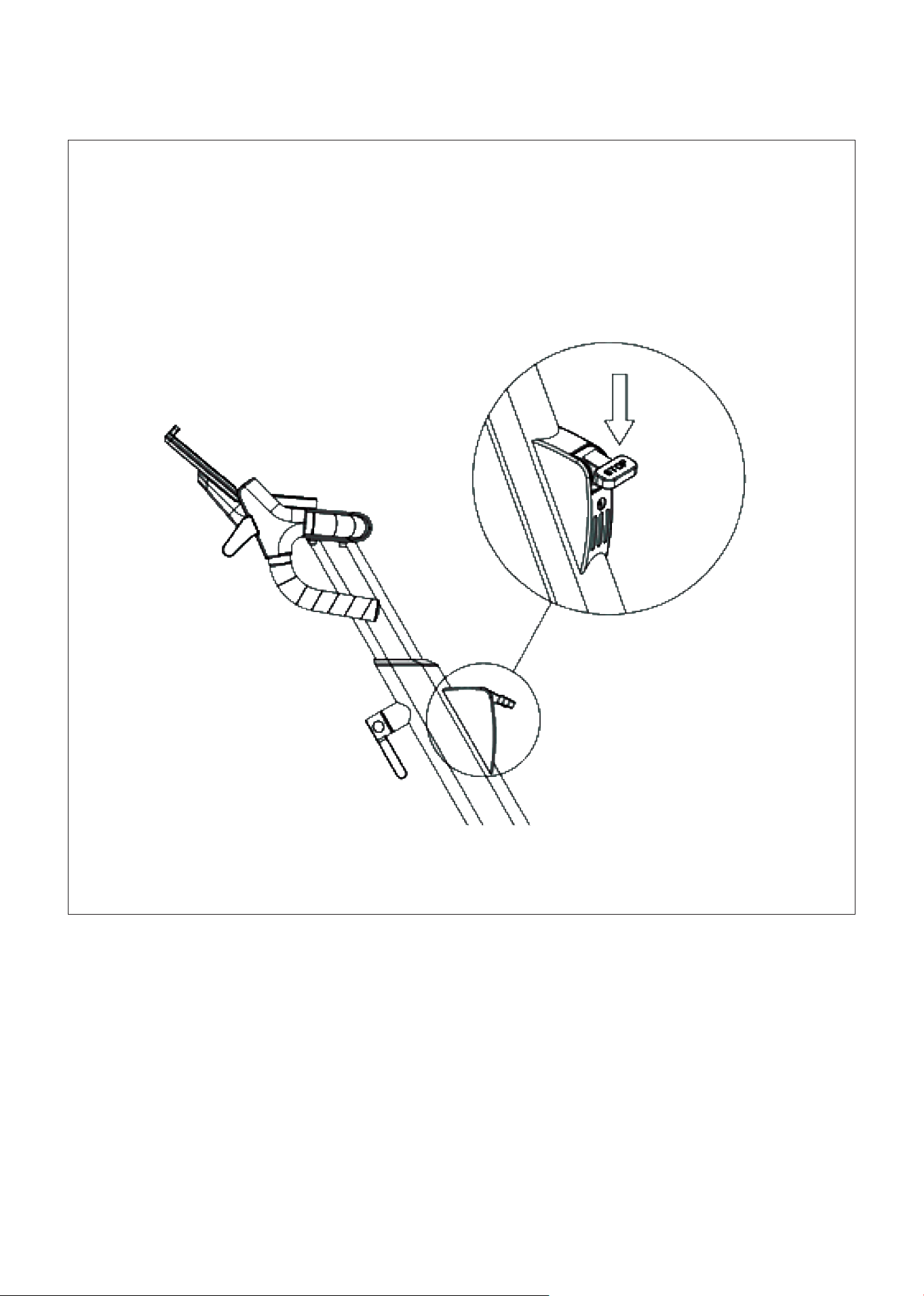
14 | EMERGENCY BRAKE USE
VI. EMERGENCY BRAKE USE
Press the brake button down to make an emergency brake.
15HOW TO MOVE THE MACHINE |
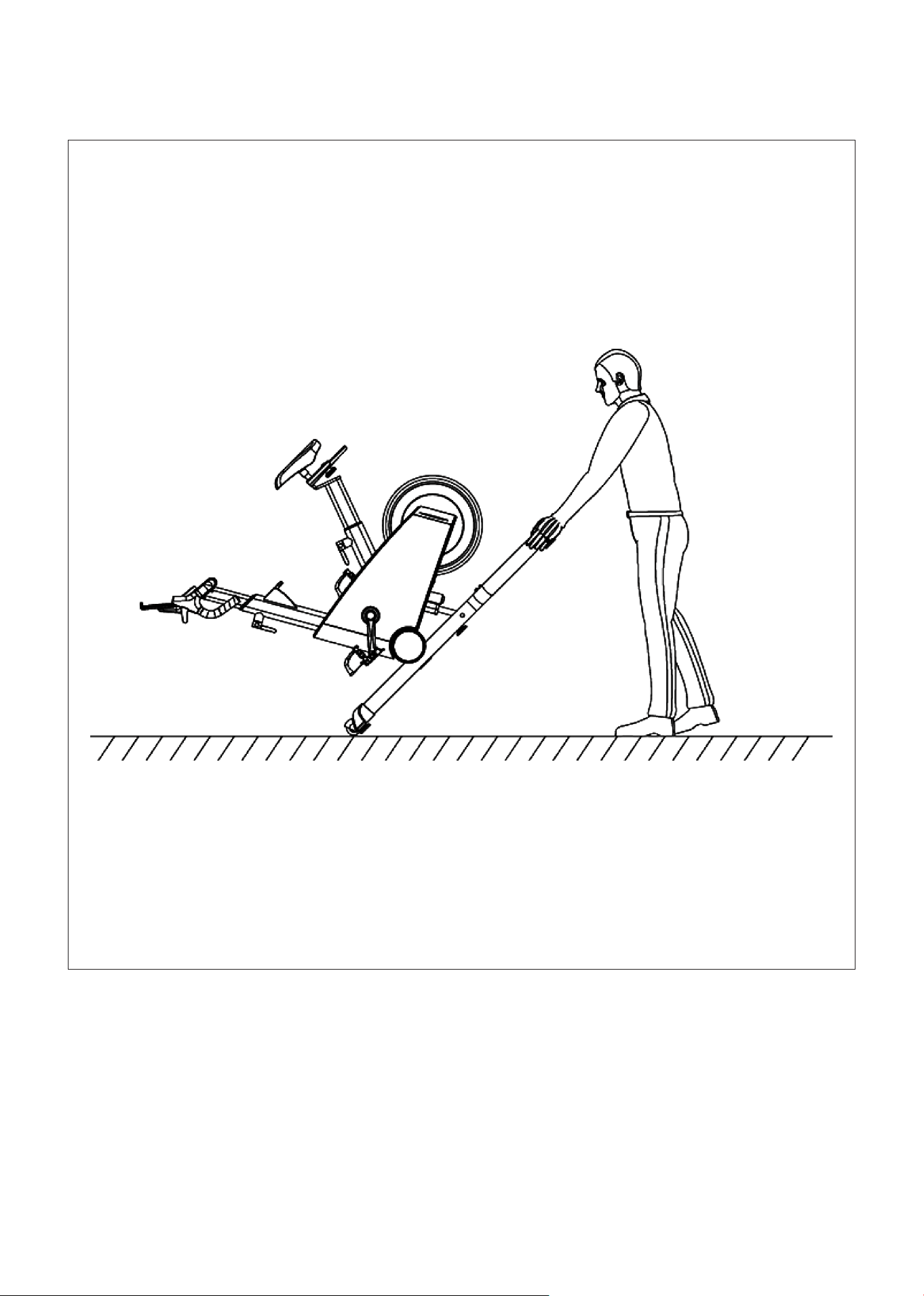
VII. HOW TO MOVE THE MACHINE
Using two hands hold the left and right rear foot tube and lift the machine about 45 degrees angle, so
that the front two moving wheels on the ground. You can only push the machine forward or pull back.
16 | COMPUTER OPERATION
VIII. COMPUTER OPERATION
WINDOW AND BUTTON DESCRIPTION
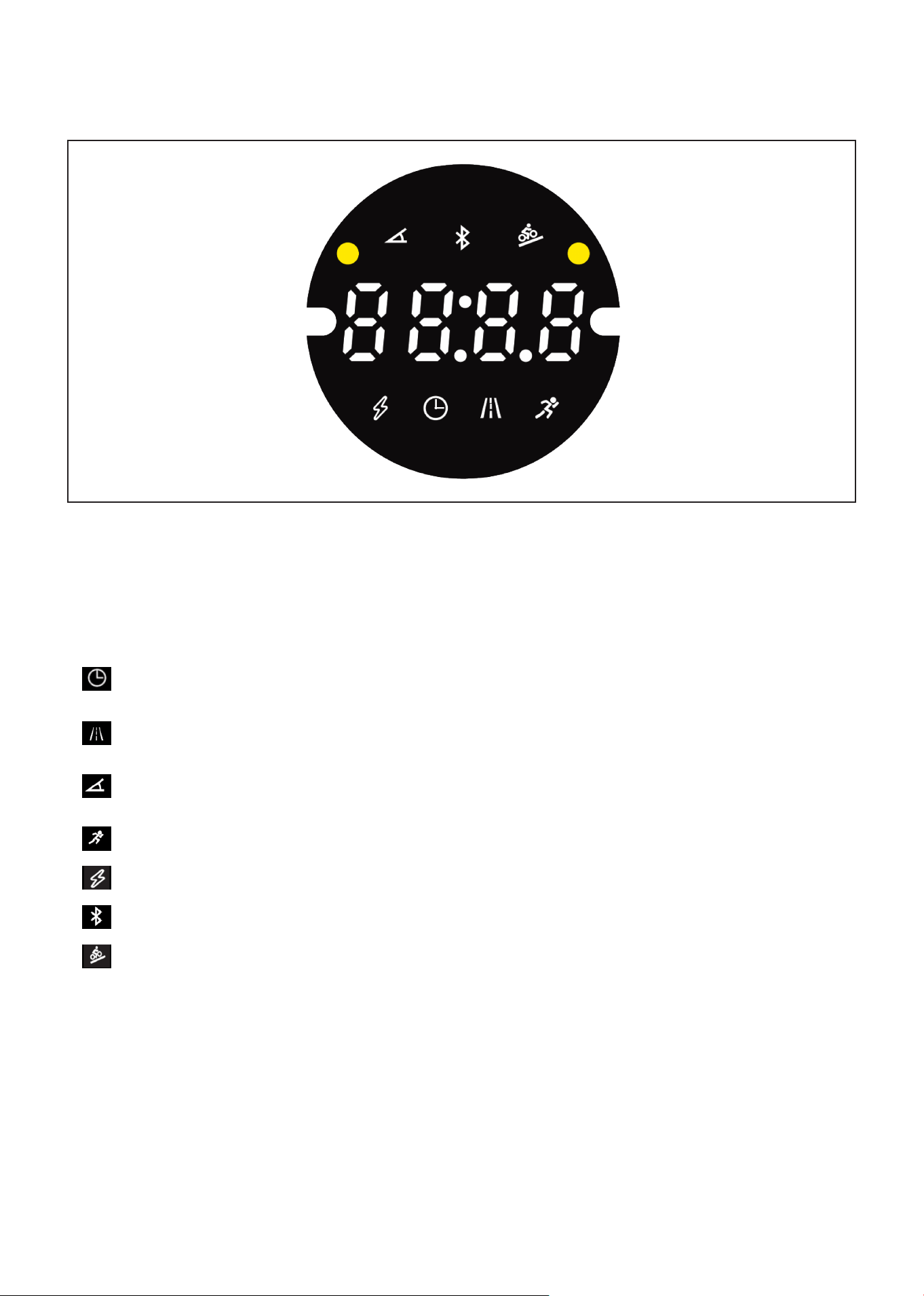
1. LED window displays the following fuctions:
A. Time Window: Displays time. Time range from 0:00-99:59, after 99:59 is reached the time will
reset to 00:00.
B. Distance Window: Displays moving distance, positive count from 0.00-99.9, clear zero after
overflow to continue running.
C. Resistance Window: Displays the current resistance gear value. Range of gear displays from
1-32 segments.
D. Speed Window: Displays the current speed value range: 0-72km/h.
E. Watt Window: Displays the current watt value of the training bike.
F. Bluetooth Icon: When there is Bluetooth access, the figure will light up.
G. Incline Icon: Displays slope values in the range -8 to 8.
2. Function Key: the center of the knob is the start and stop function key, the knob rotates clockwise for
the plus key, counterclockwise for the minus key.
A. Start/Stop Key: Press the button in the stop state, and the display will start to count.
B. Start and Stop Key: To stop and start workout. In the paused state, press for 1 second to resume the
motion, and hold down for 3 seconds to clear data.
LED window multiplexed display, in the running state 5 seconds in turn switch display, operation knob,
priority display resistance gear, operation slope, priority display slope.
BUTTON FUNCTION DESCRIPTION

17COMPUTER OPERATION |
C. Knob Clockwise Rotation: During operation, turning clockwise will increase resistance. In the
standby state, it can also be used to select the built-in program P1-P2-P3.
D. Knob Counterclockwise Rotation: During operation, turning counterclockwise will decrease
resistance. In the standby state, it can also be used to select the built-in program P1-P2-P3.
E. External Gear Addition or Subtraction Key: During operation, the current gear value can be adjusted.
F. External Slope Plus or Minus Key: During operation, the current slope value can be adjusted.
PROGRAMS
The system changes segments every 10 seconds.
INCLINE TIME
To set time/20 time = running time of each time period
1 2 3 4 5 6 7 8 9 10 11 12 13 14 15 16
P1
GEARS 10 12 16 8 2 10 16 10 2 18 10 4 12 8 12 6
INCLINE 0 6 8 -2 -8 0 8 0 -8 8 0 -6 6 -2 6 0
P2
GEARS 10 14 16 10 5 10 20 6 16 12 5 20 12 8 14 6
INCLINE 0 6 8 2 -8 0 6 -6 6 0 -8 8 2 -3 4 0
P3
GEARS 10 18 6 18 3 16 3 10 22 6 18 6 20 6 16 6
INCLINE 0 8 -8 6 -8 4 -8 0 6 -6 4 -6 6 -2 4 0
DISPLAY RANGE OF EACH VALUE
Time (min:sec) 0:00 0:00 N/A 0:00-99:59
Speed Window 0.0 0.0 N/A 0-72km/h
Gear 0 0 N/A 1-32
Distance (km) 0.0 0.0 N/A 0.0-99.9
Watt 0 0 N/A 0-9999
Incline 0 0 N/A -8-8
Initial Set Initial Value Set Range Display Range
Algorithm List:
The speed is calculated as 21.5KM/H for 60RPM.
When there is no speed signal, the distance does not count.
Sleep and Automatic Stop Function:
In the running state, if there is no speed signal within 1 minute, the system automatically enters the
suspended state. In the stopped or suspended state, the system enters the hibernated state without
any operation for 10 minutes.
In hibernation state, it can be awakened by the key knob to turn on.

18
Shutdown:
The system can be turned off at any time by turning off the power switch without damaging the
system.
Note:
1. Check that your equipment is receiving power before use.
2. If there is any problem with the machine or power cable, please contact the place of purchase.
Slope Motor Calibration
In the standby state, hold down the external incline plus or minus key for 3 seconds at the same time,
and the system will enter the automatic incline calibration. When calibration is complete, the system
will exit automatically.
If E04 is reported during the learning process, check the motor, motor signal cable, or replace the driver.
| COMPUTER OPERATION
19EXERCISE GUIDE |
IX. EXERCISE GUIDE
PLEASE NOTE:
Before beginning any exercise program, consult your physician. This is important especially if you are
over the age of 45 or individuals with pre-existing health problems.
The pulse sensors are not medical devices. Various factors, including the user’s movement, may
affect the accuracy of heart rate readings. The pulse sensors are intended only as an exercise aid in
determining heart rate trends in general.
Exercising is great way to control your weight, improving your fitness and reduce the effect of aging and
stress. The key to success is to make exercise a regular and enjoyable part of your everyday life.
The condition of your heart and lungs and how efficient they are in delivering oxygen via your blood to
your muscles is an important factor to your fitness. Your muscles use this oxygen to provide enough
energy for daily activity. This is called aerobic activity. When you are fit, your heart will not have to work
so hard. It will pump a lot fewer times per minute, reducing the wear and tear of your heart.
So as you can see, the fitter you are, the healthier and greater you will feel.
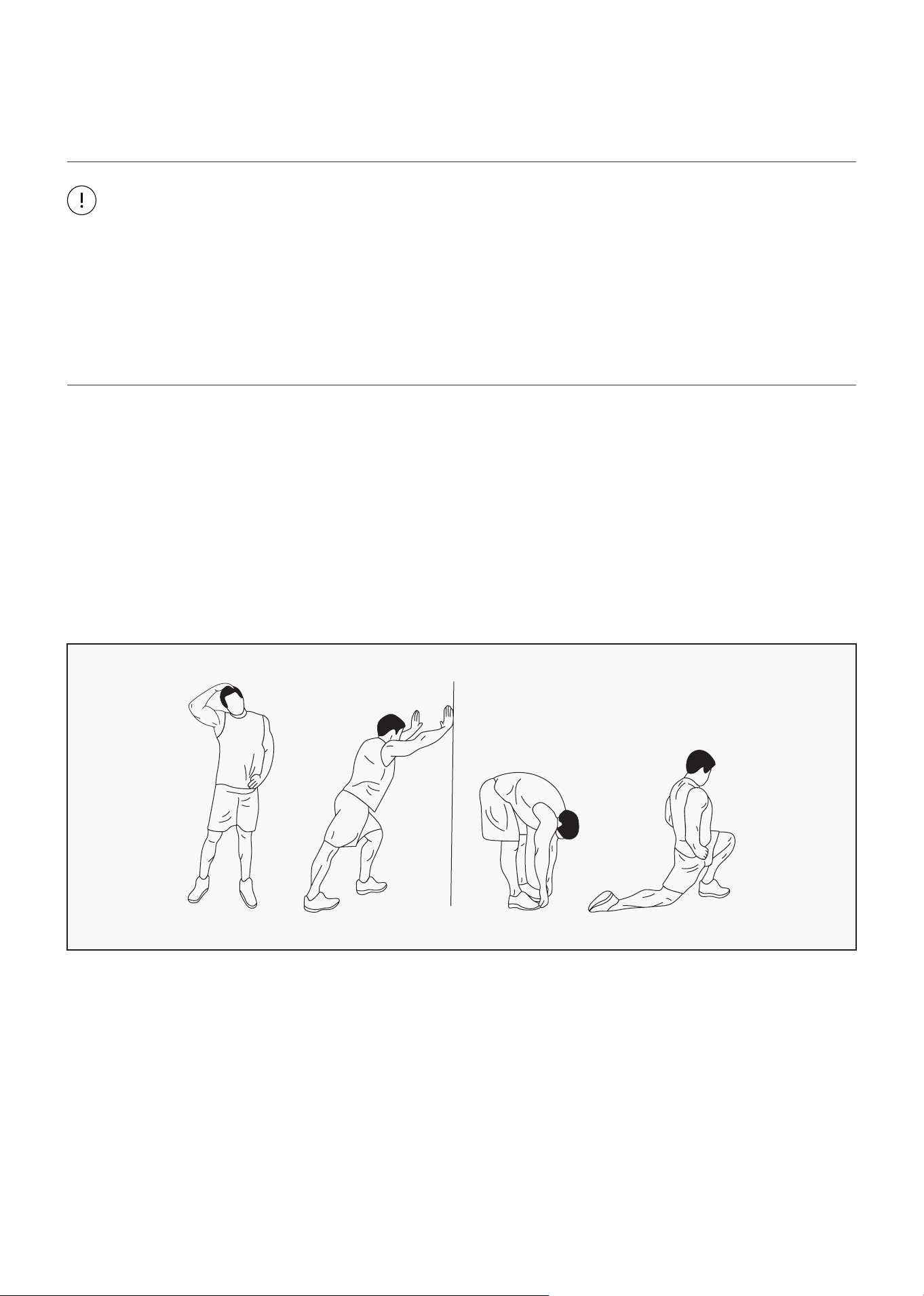
WARM UP
Start each workout with 5 to 10 minutes of stretching and some light exercises. A proper warm-up
increases your body temperature, heart rate and circulation in preparation for exercise. Ease into your
exercise.
After warming up, increase the intensity to your desired exercise program. Be sure to maintain your
intensity for maximum performance. Breathe regularly and deeply as you exercise.
20
COOL DOWN
Finish each workout with a light jog or walk for at least 1 minute. Then complete 5 to 10 minutes of
stretching to cool down. This will increase the flexibility of your muscles and will help prevent post-
exercise problems.
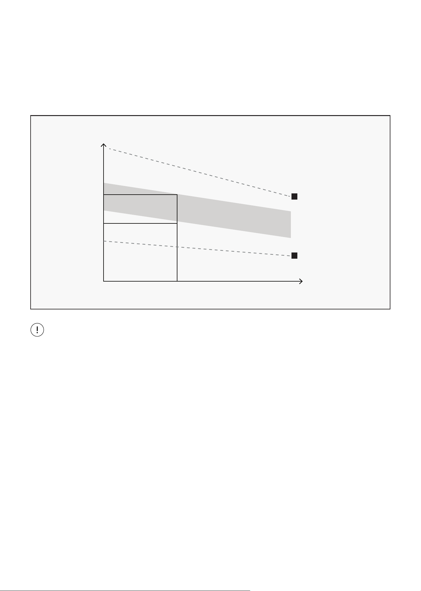
WORKOUT GUIDELINES
This is how your pulse should behave during general fitness exercise. Remember to warm up and
cool down for a few minutes.
TARGET ZONE
MAXIMUM
85%
70%
COOL DOWN
AGE
HEART RATE
200
180
160
140
120
100
80
20 25 30 35 40 45 50 55 60 65 70 75
| EXERCISE GUIDE

21
X. WARRANTY
AUSTRALIAN CONSUMER LAW
Many of our products come with a guarantee or warranty from the manufacturer. In addition, they come
with guarantees that cannot be excluded under the Australian Consumer Law. You are entitled to a
replacement or refund for a major failure and compensation for any other reasonably foreseeable loss
or damage.
You are entitled to have the goods repaired or replaced if the goods fail to be of acceptable quality and
the failure does not amount to a major failure. Full details of your consumer rights may be found at
www.consumerlaw.gov.au.
Please visit our website to view our full warranty terms and conditions:
http://www.lifespanfitness.com.au/warranty-repairs
WARRANTY AND SUPPORT
Any claim against this warranty must be made through your original place of purchase.
Proof of purchase is required before a warranty claim may be processed.
If you have purchased this product from the Official Lifespan Fitness website, please visit
https://lifespanfitness.com.au/warranty-form
For support outside of warranty, if you wish to purchase replacement parts or request a repair or
service, please visit https://lifespanfitness.com.au/warranty-form and fill in our Repair/Service
Request Form or Parts Purchase Form.
Scan this QR code with your device to go to lifespanfitness.com.au/warranty-form
WARRANTY |


WWW.LIFESPANFITNESS.COM.AU