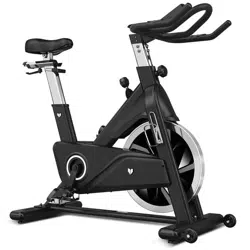
SM-420 Spin Bike with Automatic
Magnetic Resistance
USER MANUAL
Product may vary slightly from the item pictured due to model upgrades.
Read all instructions carefully before using this product.
Retain this owner’s manual for future reference.
NOTE:
This manual should not be used to guide your purchasing decision. Your product, and the contents inside its carton, may vary
from what is listed in this manual. This manual may also be subject to updates or changes. Updated manuals are available
through our website at www.lifespanfitness.com.au
Find the
Digital Manual
Online

2
TABLE OF
CONTENTS
I. Important Safety Instructions . . . . . . . . . . . . . . . . . . . . . . . . . . . . . . . 03
II. Care Instructions . . . . . . . . . . . . . . . . . . . . . . . . . . . . . . . . . . . . . . . . . . . . . 04
III. Exploded Diagram . . . . . . . . . . . . . . . . . . . . . . . . . . . . . . . . . . . . . . . . . . . . 05
IV. Parts List . . . . . . . . . . . . . . . . . . . . . . . . . . . . . . . . . . . . . . . . . . . . . . . . . . . . . . 06
V. Assembly Instructions . . . . . . . . . . . . . . . . . . . . . . . . . . . . . . . . . . . . . . . . 08
VI. Operation Guide . . . . . . . . . . . . . . . . . . . . . . . . . . . . . . . . . . . . . . . . . . . . . . 17
VII. Exercise Guide . . . . . . . . . . . . . . . . . . . . . . . . . . . . . . . . . . . . . . . . . . . . . . . . 21
VIII. Warranty . . . . . . . . . . . . . . . . . . . . . . . . . . . . . . . . . . . . . . . . . . . . . . . . . . . . . . 23
| TABLE OF CONTENTS

3IMPORTANT SAFETY INSTRUCTIONS |
I. IMPORTANT SAFETY
INSTRUCTIONS
WARNING: Read all instructions before using this machine.
It is important your machine receives regular maintenance to prolong its useful life. Failing to
regularly maintain your machine may void your warranty.
Please always keep this manual with you.
• It is important to read this entire manual before assembling and using the equipment. Safe and
effective use can only be achieved if the equipment is assembled, maintained, and used properly.
PLEASE NOTE: It is your responsibility to ensure that all users of the equipment are informed of all
warnings and precautions
• Before starting any exercise program, you should consult your doctor to determine if you have any
medical or physical conditions that could put your health and safety at risk, or prevent you from
using the equipment properly. Your doctor’s advice is essential if you are taking medication that
affects your heart rate, blood pressure or cholesterol level.
• Be aware of your body’s signals. Incorrect or excessive exercise can damage your health. Stop
exercising if you experience any of the following symptoms: pain, tightness in your chest, irregular
heartbeat, and extreme shortness of breath, lightheadedness, dizziness, or feelings of nausea. If you
do experience any of these symptoms, you should consult your doctor before continuing with your
exercise program.
• Keep children and pets away from the equipment. This equipment is designed for adult use only.
• Use the equipment on a solid, flat level surface with a protective cover for your floor or carpet.
To ensure safety, the equipment should have at least 2 meters of free space around it.
• Before using the equipment, check that the nuts and bolts are securely tightened. If you hear any
unusual noises coming from the equipment during use and assembly, stop immediately. Do not use
the equipment until the problem has been rectified.
• Wear suitable clothing while using the equipment. Avoid wearing loose clothing that may get caught
vin the equipment or that may restrict or prevent movement.
• This equipment is designed for indoor and family use only.
• Care must be taken when lifting or moving the equipment so as not to injure your back.

4
• Always keep this instruction manual and assembly tools at hand for reference.
• The equipment is not suitable for therapeutic use.
• The pulse or heart rate sensors are not medical devices. Various factors, including the user’s
movement, may affect the accuracy of heart rate readings. The pulse sensors are intended only as
exercise aids in determining heart rate trends in general.
| CARE INSTRUCTIONS
II. CARE INSTRUCTIONS
IMPORTANT
a. All nuts and bolts are to be checked and tightened on a regular basis. This includes pedals and other
moving parts. Failure to do so may cause damage to your threads and void your warranty.
b. Lubricate moving joints after periods of usage.
c. Be careful not to damage plastic or metal parts of the machine with heavy or sharp objects.
d. The machine can be kept clean by wiping it down using dry cloth.
Power Adapter Information
Input: 100-240V 50/60Hz
Output: 9V 1000mA
5EXPLODED DIAGRAM |
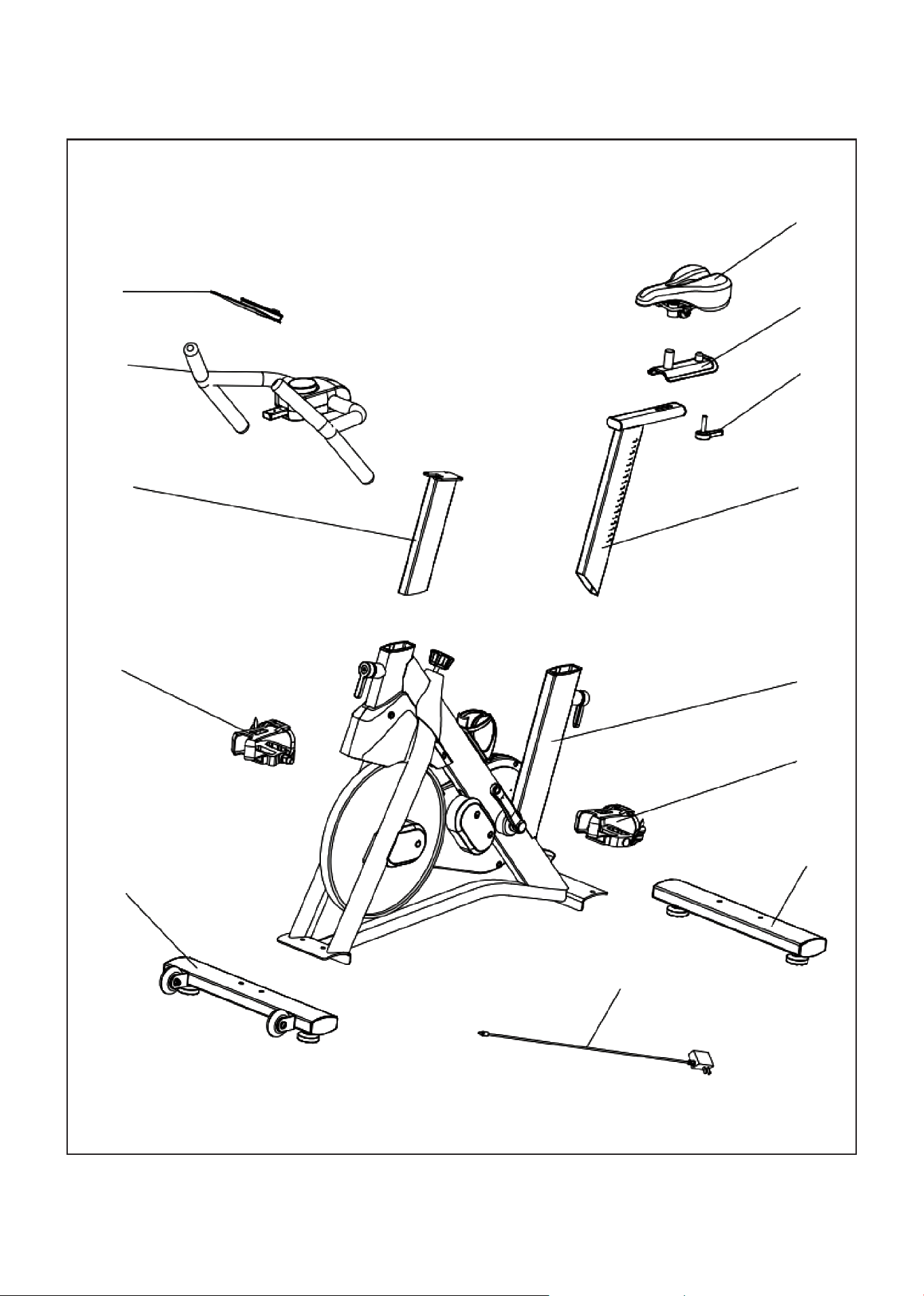
III. EXPLODED DIAGRAM
12
11
10
9
8
1
2
3
4
5
6
7
13
6 | PARTS LIST
IV. PARTS LIST
No. Description Qty
1 Seat cushion 1
2 Front and rear adjustment support 1
3 Cushion adjusting knob 1
4
Seat cushion adjusting pipe
assembly
1
5
Main frame assembly
1
6
Left foot pedal
1
7
Rear foot tube assembly
1
No. Description Qty
8 Front foot tube assembly 1
9 Right pedal 1
10 Handrail adjusting pipe 1
11
Handrail assembly
1
12
IP Assembly
1
13
External power adapter
1
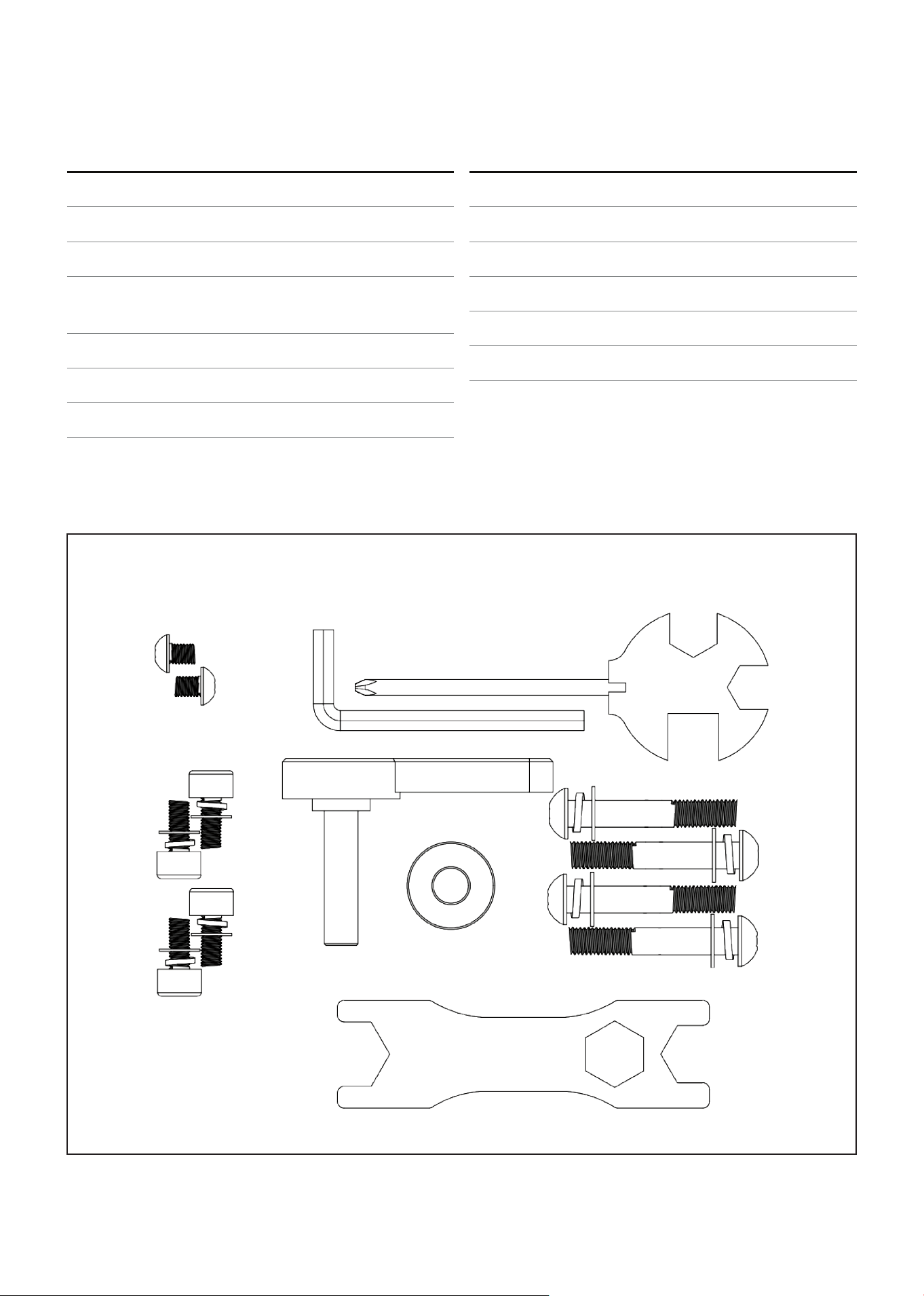
PARTS PACKAGE
TOOLS & ACCESSORIES
Allen Wrench
Inner hexagon soanner (5#)
Bolt M5*7 2pcs.
SHCS M6*15 4pcs.
Washer 6 4pcs.
Standard Elastic Washer 4pcs.
Adjustment Handle Seat
Big Washer 10 1pc.
Wrench (S17-19) 2pcs.
Bolt M8*50 4pcs.
Washer 8 4pcs.
Standard
Elastic Washer 4pcs.
7PARTS LIST |
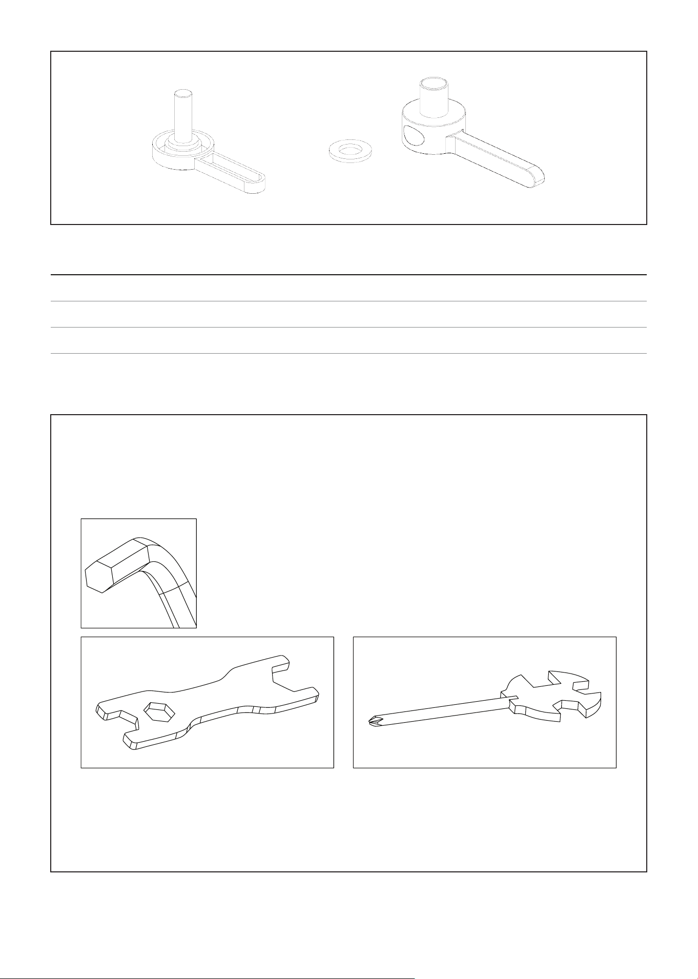
A B C
Item Qty Description
A 1 L-shaped adjusting handle is short
B 1 Flat washer
C 2 Length of L-shaped adjusting handle
INSTALLATION TOOLS
5mm 13
17mm, 19mm 13mm, 14mm, 15mm
8
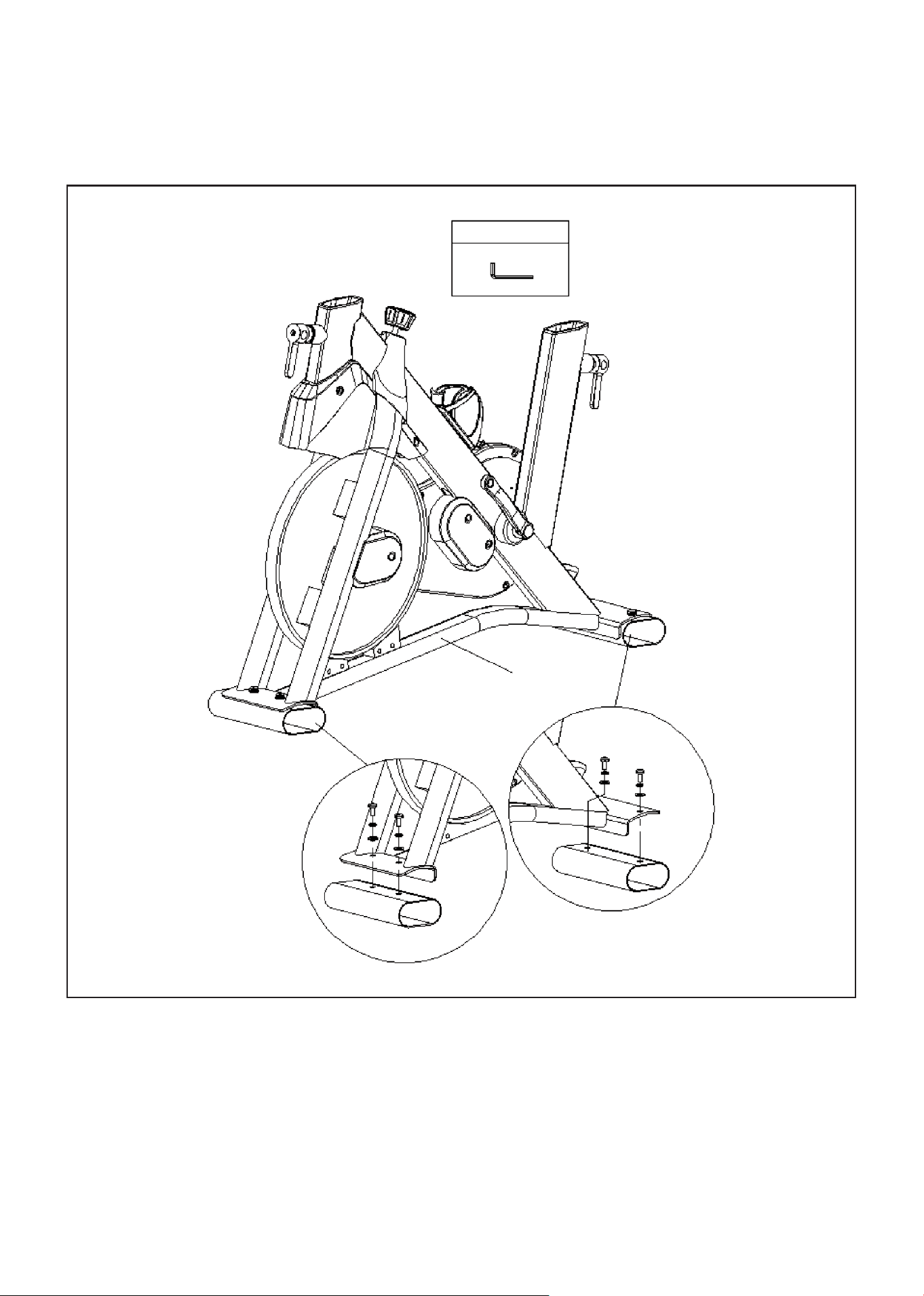
V. ASSEMBLY INSTRUCTIONS
Some parts may be pre-fitted to the equipment.
1. Remove the hexagon flat head screw, standard spring washer and flat washer on the packing foot
tube with a 5 # hexagon wrench.
2. Discard the removed packing foot tube, internal hexagon flat round head screw, standard spring
washer and flat washer.
STEP 1
| ASSEMBLY INSTRUCTIONS
TOOLS
5
9ASSEMBLY INSTRUCTIONS |
1. Use scissors to cut the knot tied to the limit board, and then remove the two boards fixed to the
frame assembly (5).
2. The four fixing wood blocks (H) sandwiched on both sides of the flywheel should also be removed.
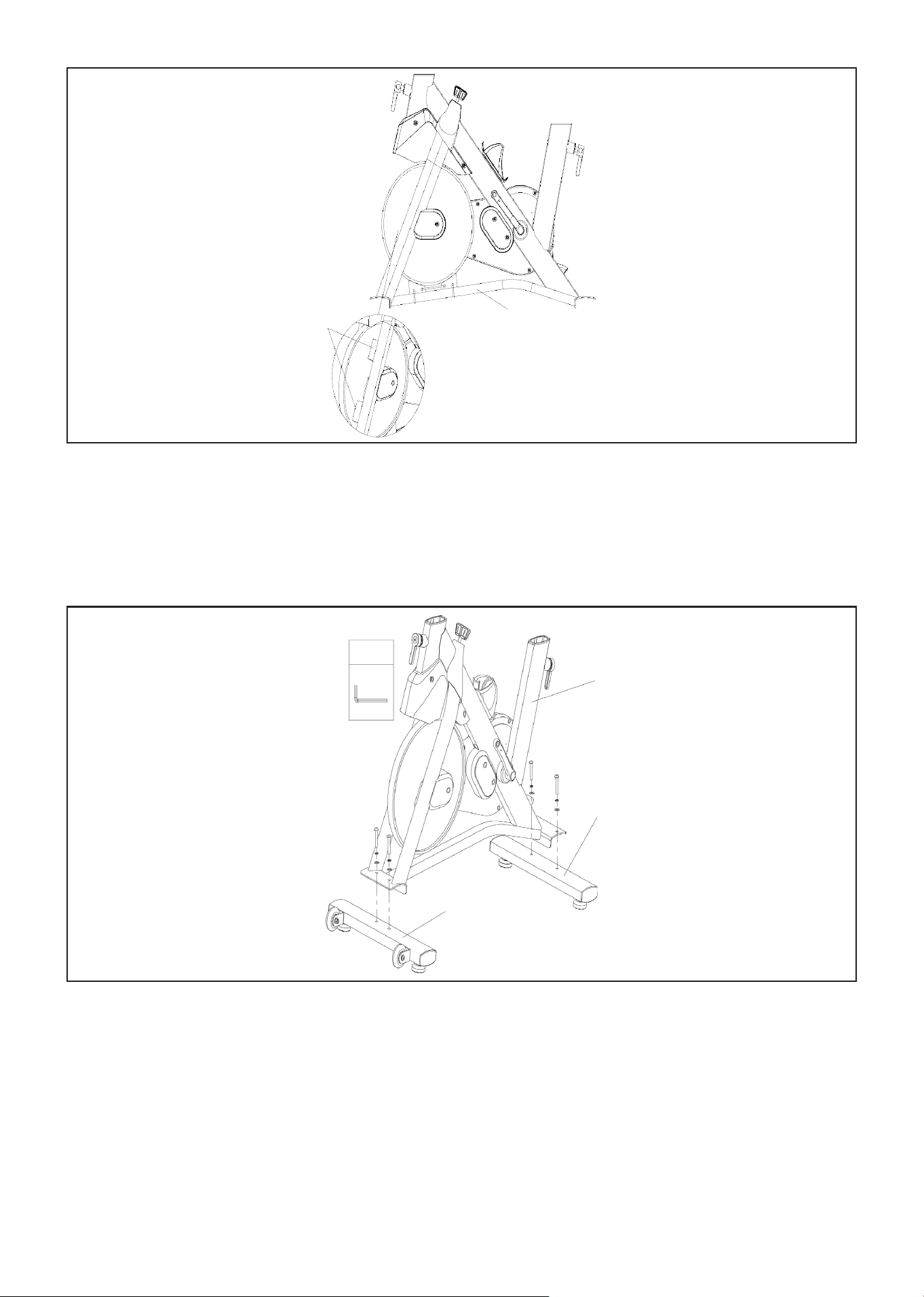
STEP 2
1. Lock the front foot tube assembly (8) to the frame assembly (5) using the 5 # socket wrench, 4x
socket flat round head screw, 4x standard spring washer and 4x flat washer in the parts package, and
install the rear foot tube assembly (7) in the same way.
NOTE: Please make sure that the parts of the auxiliary packaging are cleaned before starting
assembly. The board of flywheel limit must be removed!
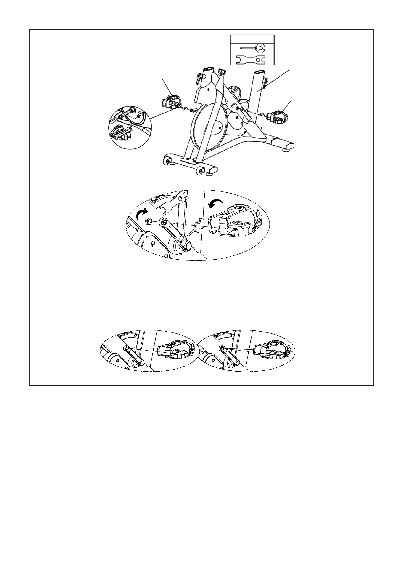
STEP 3
H
5
TOOLS
5
7
8
10 | ASSEMBLY INSTRUCTIONS
1. Distinguish the left and right pedals from the labels.
2. Remove the nut on the pedal part.
3. Left Pedal: First, hand tighten and install the pedal by turning it anti-clockwise and once its all the
way through the crank shaft, secure the nut on the other side of the pedal shaft by turning it
clockwise. Make sure to then tighten both sides at the same time using a wrench by turning it
clockwise for the nut and anti-clockwise for the pedal (Fig. A).
4. Right pedal: Repeat the same steps 2-3.
STEP 4
TOOLS
9
5
6
FIG A
FIG B
Correct Incorrect
IMPORTANT: Before tightening make sure the pedal shaft and crank are perpendicular when assembling (Fig. B).
The Right pedal should be threaded on clockwise and the Left pedal anticlockwise and the nut going in opposite
directions to the pedals.
Ensure to fully tighten both pedals as loose pedals will cause damage to the thread and this will affect your warranty.
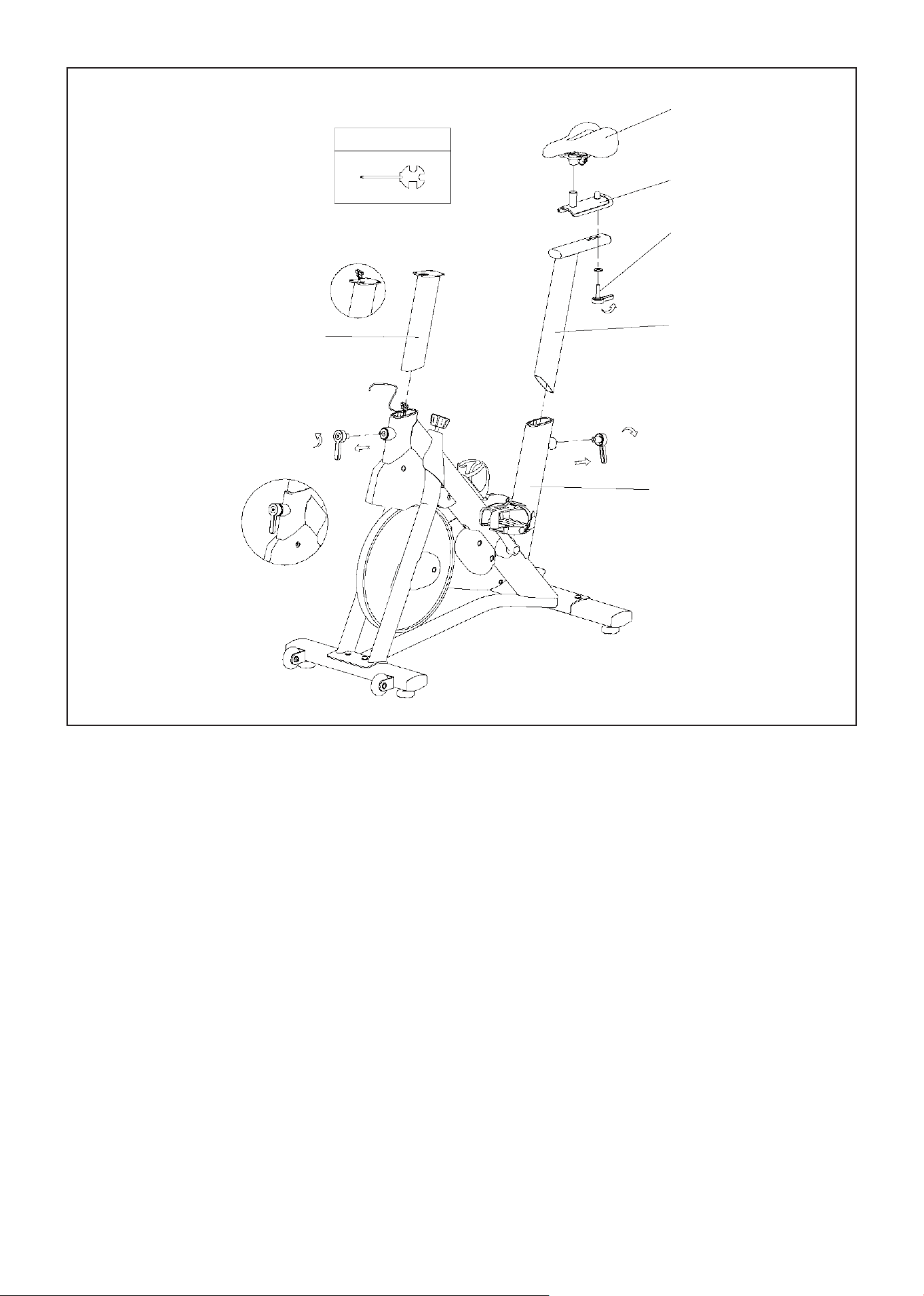
11ASSEMBLY INSTRUCTIONS |
1. Loosen the guide wire and use the guide wire to pass the wiring head through the armrest
adjustment assembly (10), as shown in Figure A.
2. Loosen the L-shaped adjustable handle at the front by turning anti-clockwise and pulling up handle
as shown on image. Then install the armrest adjusting assembly (10) onto the main frame (5) of the
machine. Lock the L-shaped adjustable handle after adjusting to the desired height.
3. Loosen the L-shaped adjustable handle then install the seat cushion adjusting pipe assembly (4) on
the main frame (5) of the machine according to the direction shown in the figure. Lock the L-shaped
adjustable handle after adjusting to the desired height.
4. Install the seat cushion front and rear adjustment support group (2) to the seat cushion adjustment
pipe assembly (4) and lock it with the seat cushion adjustment knob.
5. Install the seat cushion (1) on the front and back adjustment support group (2) of the seat cushion.
After adjusting the seat angle, secure it by tightening the nut on both sides at the same time (left nut
anti-clockwise, right nut clockwise).
STEP 5
TOOLS
1
2
3
4
5
10
A
B
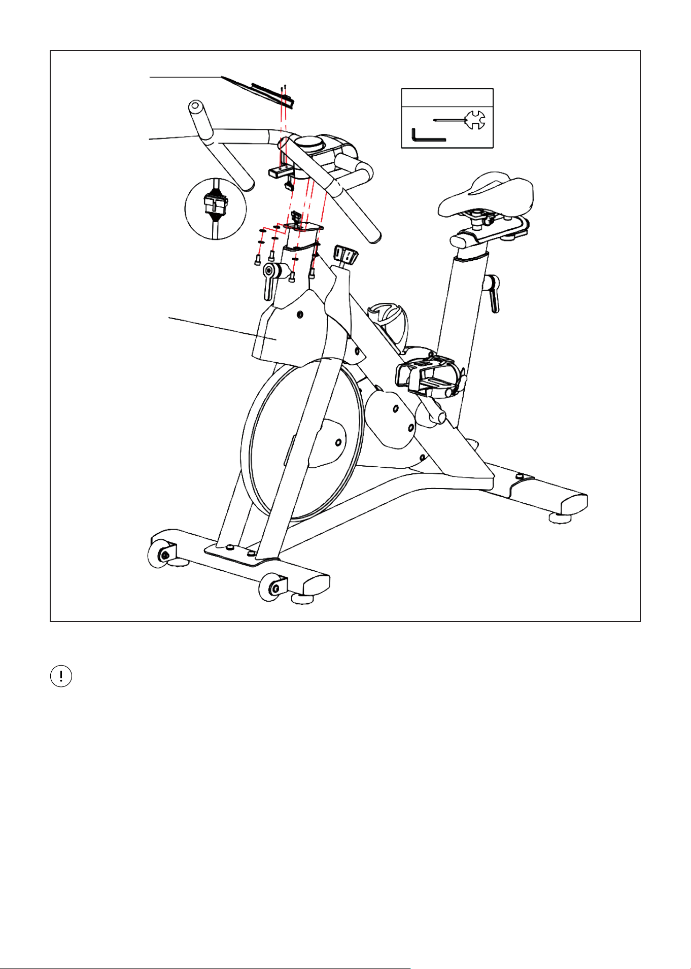
12 | ASSEMBLY INSTRUCTIONS
1. Remove the guide wire on the armrest adjusting assembly (10), and then connect the connector wire
on the armrest adjusting assembly (11) with the connector wire on the armrest adjusting assembly
(10), as shown in Figure A.
2. Install the armrest assembly (11) to the armrest adjustment assembly (10) with a 5 # socket wrench
and 4x socket flat round head screw, 4x standard spring washer, 4x flat washer.
3. Secure the IP rack assembly (12) to the armrest assembly (11) with a cross wrench and 2x cross
slotted pan head bolt M5*7.
STEP 6
TOOLS
12
11
5
A
CAUTION: When installing the handlebars be careful not to damage the cables. Once cables are
connected do not get it caught on the brackets and that they are fully inside the tube.
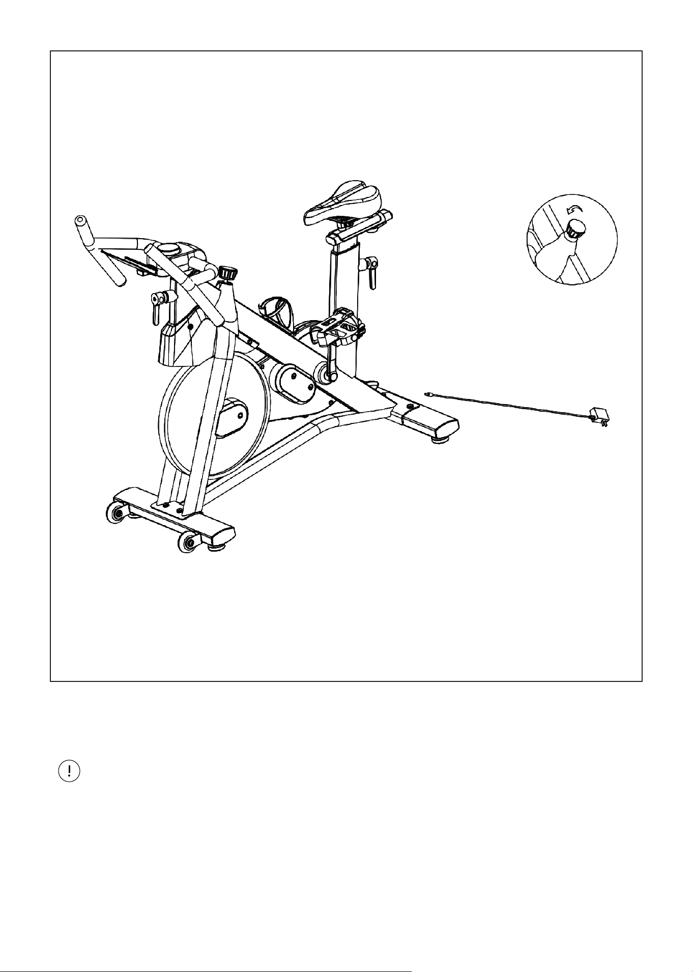
13ASSEMBLY INSTRUCTIONS |
1. Connect the power adapter at the bottom rear of the spin bike frame. Use the equipment according to
the operation instructions.
STEP 7
CAUTION: Turn the brake handle counter-clockwise to the bottom before plugging in, leaving the
brake handle in a non-clasping state.
14 | ASSEMBLY INSTRUCTIONS
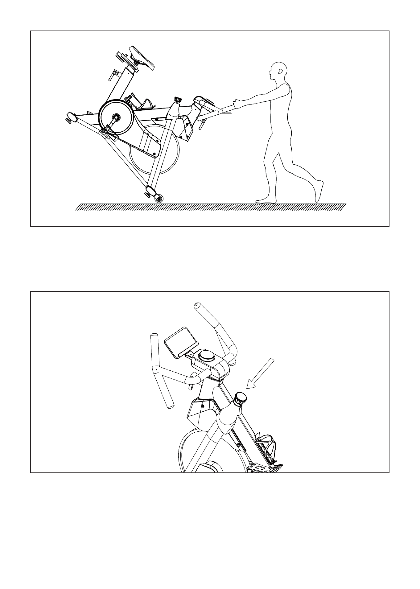
1. When moving the machine, grab the front end of the handle and push it down, so that the rollers on
the foot tube are completely in contact with the ground, then start moving the machine to your
desired location.
TRANSPORTATION WHEELS
If you want to stop after reaching a certain speed during movement, you can place your hand on the
knob and press it down to increase resistance to the wheels, causing them to stop quickly to avoid
injuring your feet.
EMERGENCY BRAKE USAGE METHOD:
15ASSEMBLY INSTRUCTIONS |
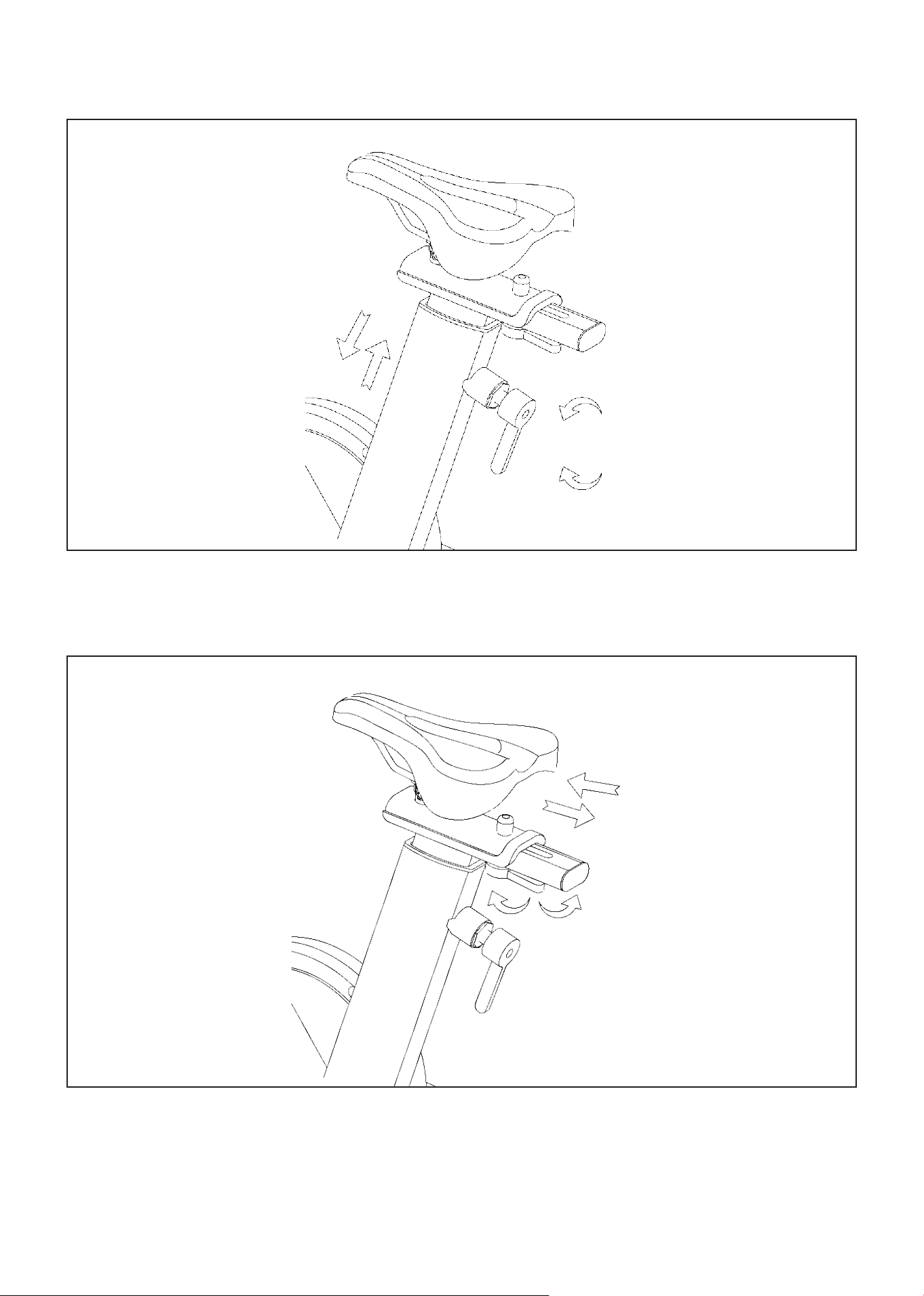
SEAT ADJUSTMENT
Seat Height Adjustment: Rotate the L-shaped adjustable handle counterclockwise with one hand, hold
the seat cushion with the other hand, then pull it up (or push it down) to adjust to the desired position.
Then turn the L-shaped adjustable handle clockwise to tighten.
Seat Fore/Backward Adjustment: Release the seat cushion adjustment knob, slide the seat cushion
back and forth, adjust to the desired position, and then tighten the knob.
16 | ASSEMBLY INSTRUCTIONS
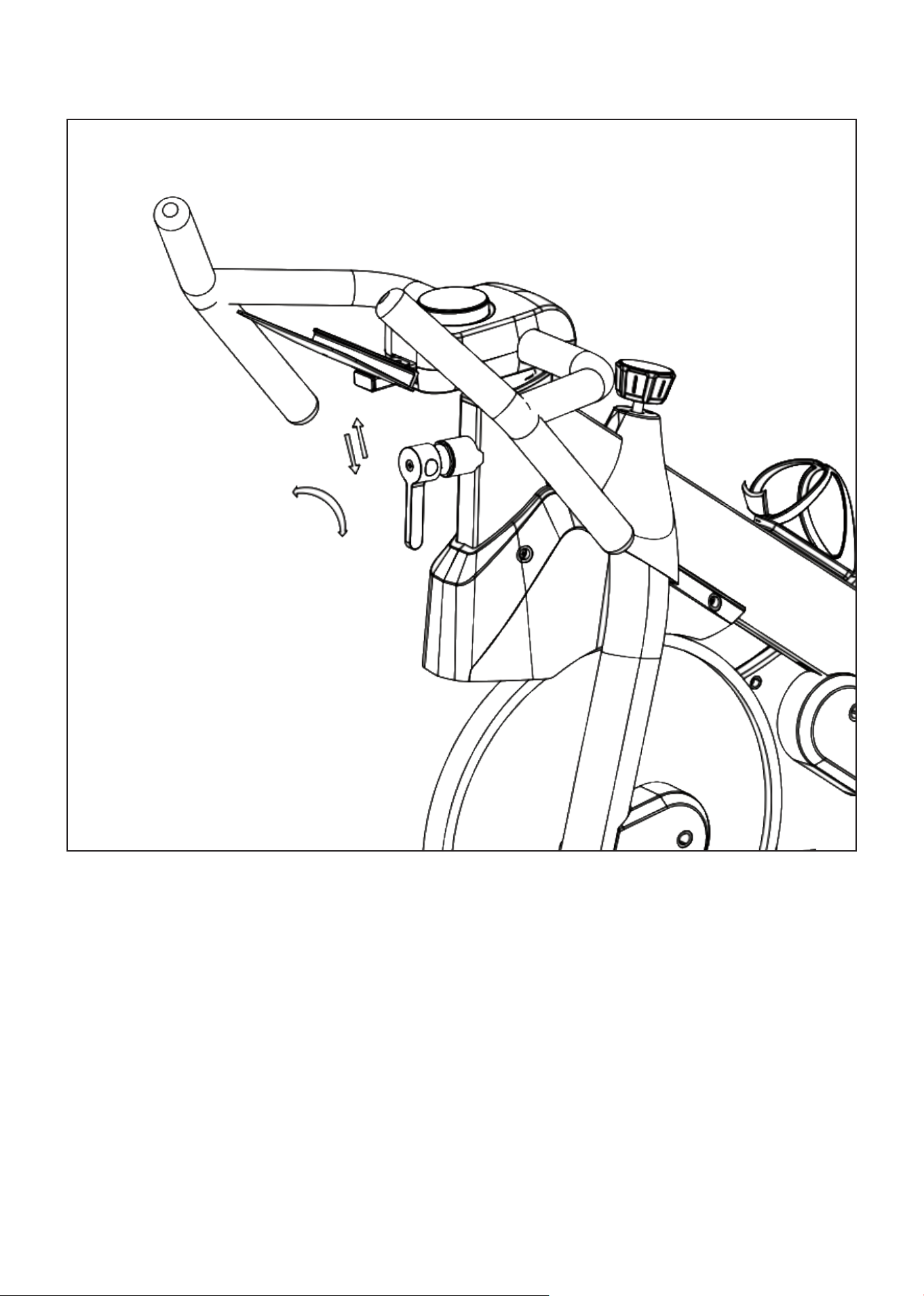
HANDLEBAR ADJUSTMENT
Handlebar Height Adjustment: Rotate the L-shaped adjustable handle counterclockwise with one
hand, grab the armrest with the other hand and pull it up (or push it down) to adjust to the desired
position. Then turn the L-shaped adjustable handle clockwise to tighten.
17
VI. OPERATION GUIDE
OPERATION GUIDE |
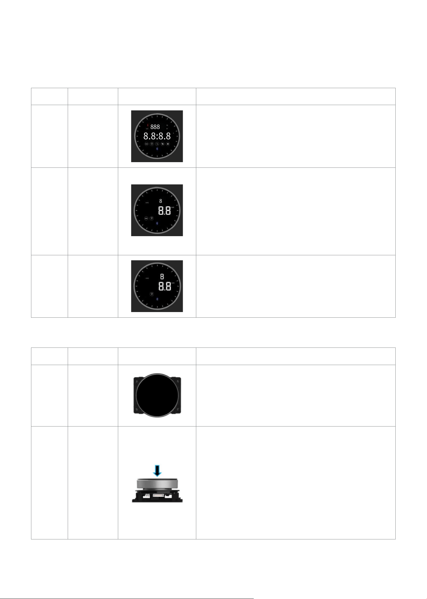
1.1 DESCRIPTION IS DISPLAYED
Item No. Items Display Window Brief Instructions
1 Full View
1. Outer ring shows 24 effect lights
2. Displays Level (resistance); Resistance values
from 1-16.
3. Displays Speed, Time, Distance (km/hr) and Calories.
4. Displays Bluetooth connectivity.
2 Scan Mode
1. Data Rotation: Data switches view every 3 seconds.
2. Small Window: Displays level of resistance.
3. Mainstream Window: Displays Speed, Time,
Distance, Calories.
4. Bluetooth: When Bluetooth is connected the light
is lit.
5. In motion stat the outer lines are lit by default.
3 Lock Mode
1. Short press the display to switch views and lock to
the data you wish to view.
2. You can lock it to see Speed, Time, Distance or
Calories on the main window.
3. Resistance level is shown on the small window.
1.2 MAIN OPERATION DESCRIPTION
Item No. Items Display Window Brief Instructions
1 Sleep Mode
Display will go black after 3 minutes of inactivity.
Press the display face to turn on.
2
Display
Functions
Short press:
1. When in sleep mode, press the display face to
turn on.
2. When display is on, short press to start the counting.
3. In motion state, short press to switch display modes.
Long Press (3 secs):
1. In motion state, long press to reset the data and
enter the main face view.
Press the display will emit a buzzer noise.
18 | OPERATION GUIDE
Item No. Items Display Window Brief Instructions
3
Rotation: During motion state, turn the dial clockwise
for more resistance and anti-clockwise for less
resistance.
A sound is generated when rotating.
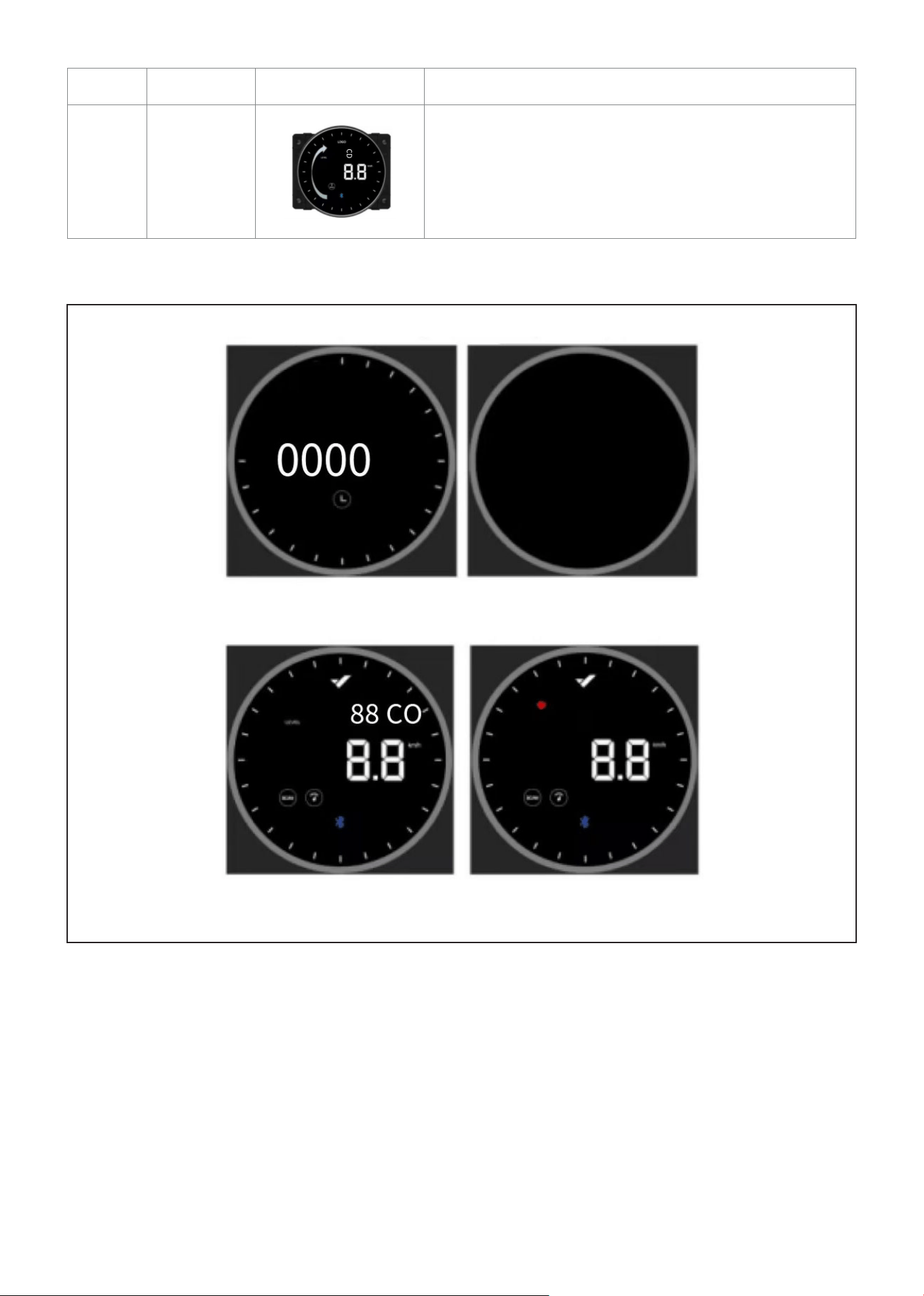
1.3 DISPLAY OPERATIONS
Ready State
1. Press the display to turn it on. A sound is generated during start up and the display enters the "Ready"
state (Fig. 1). Resistance levels during start up will automatically be set as level 1. If there is inactivity
after 3 minutes the display will turn off again (Fig. 2).
2. In the Ready state, press the display face or start pedaling to enter Motion state. If pulse sensor is
supported, the small window with show Pulse and resistance Level and will switch between the 2 data
every 3 seconds (Fig.3 and Fig.4). The window will only display Level if Pulse is not supported.
FIG 1 FIG 2
FIG 3 FIG 4
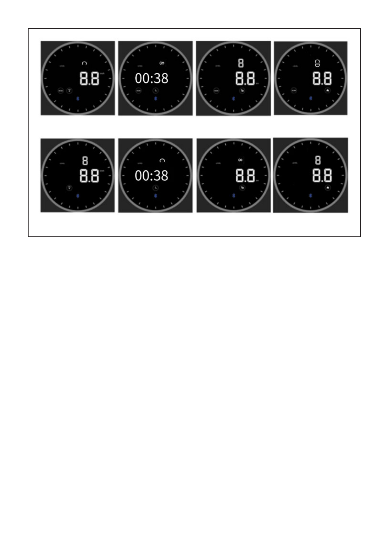
19OPERATION GUIDE |
Scan Mode
3. The numbers in the main window are rotated by default when the scan icon is lit up. Speed, Time,
Distance and Calories will switch every 3 seconds (Fig. 5-8).
4. The display mode can be adjusted to lock your view by short press the display face so that "Scan" icon
is not displayed. You can lock the view to fixed data of: Speed, Time, Distance or Calories (Fig. 9-12).
FIG 5 FIG 6 FIG 7 FIG 8
FIG 9 FIG 10 FIG 11 FIG 12
20| OPERATION GUIDE
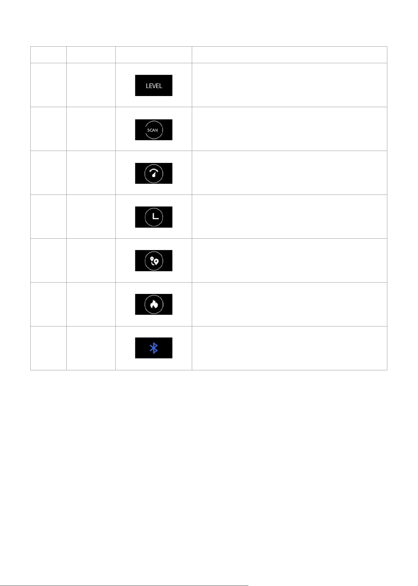
1.4 DATA DISPLAY DESCRIPTION
Item No. Items Display Window Brief Instructions
1
Resistance
Levels
Resistance levels 1-16. Higher gear is more resistance.
2 Scan
When Scan is lit up, the display will scan through the
other Data. When not lit up it will be locked on the
selected display mode.
3 Speed
Values display as 0.0-999.9 km/hr, 60RPM-21.5 km/hr.
It will reset to 0.0 once the maximum value is reached.
4 Time
Values display as 00:00-99:59. Short press to start the
time. It will reset to 00:00 once the maximum value is
reached.
5 Distance
Values display as 0.0-999.9 km. It will reset to 00:00
once the maximum value is reached.
6 Calories
Values display as 0.0-999.9 kcal. It will reset to 000.0
kcal once the maximum value is reached.
7
Bluetooth
icon
If the Bluetooth icon is present then it is connected. If
it is not present then it is not connected.
21
VII. EXERCISE GUIDE
PLEASE NOTE:
Before beginning any exercise program, consult your physician. This is important especially if you are
over the age of 45 or individuals with pre-existing health problems.
The pulse sensors are not medical devices. Various factors, including the user’s movement, may
affect the accuracy of heart rate readings. The pulse sensors are intended only as an exercise aid in
determining heart rate trends in general.
Exercising is great way to control your weight, improving your fitness and reduce the effect of aging and
stress. The key to success is to make exercise a regular and enjoyable part of your everyday life.
The condition of your heart and lungs and how efficient they are in delivering oxygen via your blood to
your muscles is an important factor to your fitness. Your muscles use this oxygen to provide enough
energy for daily activity. This is called aerobic activity. When you are fit, your heart will not have to work
so hard. It will pump a lot fewer times per minute, reducing the wear and tear of your heart.
So as you can see, the fitter you are, the healthier and greater you will feel.
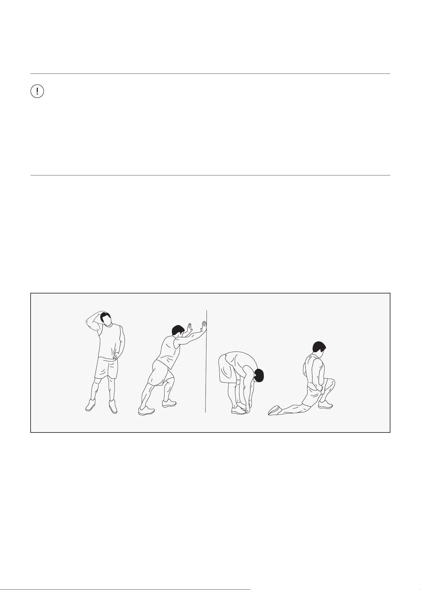
WARM UP
Start each workout with 5 to 10 minutes of stretching and some light exercises. A proper warm-up
increases your body temperature, heart rate and circulation in preparation for exercise. Ease into your
exercise.
After warming up, increase the intensity to your desired exercise program. Be sure to maintain your
intensity for maximum performance. Breathe regularly and deeply as you exercise.
EXERCISE GUIDE |
22
COOL DOWN
Finish each workout with a light jog or walk for at least 1 minute. Then complete 5 to 10 minutes of
stretching to cool down. This will increase the flexibility of your muscles and will help prevent post-
exercise problems.
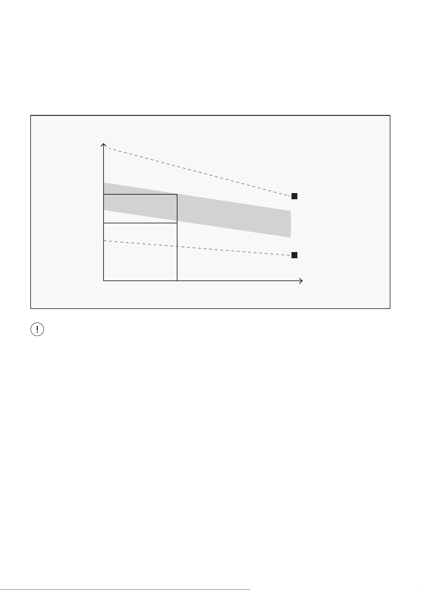
WORKOUT GUIDELINES
This is how your pulse should behave during general fitness exercise. Remember to warm up and
cool down for a few minutes.
TARGET ZONE
MAXIMUM
85%
70%
COOL DOWN
AGE
HEART RATE
200
180
160
140
120
100
80
20 25 30 35 40 45 50 55 60 65 70 75
| EXERCISE GUIDE

23
VIII. WARRANTY
AUSTRALIAN CONSUMER LAW
Many of our products come with a guarantee or warranty from the manufacturer. In addition, they come
with guarantees that cannot be excluded under the Australian Consumer Law. You are entitled to a
replacement or refund for a major failure and compensation for any other reasonably foreseeable loss
or damage.
You are entitled to have the goods repaired or replaced if the goods fail to be of acceptable quality and
the failure does not amount to a major failure. Full details of your consumer rights may be found at
www.consumerlaw.gov.au.
Please visit our website to view our full warranty terms and conditions:
http://www.lifespanfitness.com.au/warranty-repairs
WARRANTY AND SUPPORT
Any claim against this warranty must be made through your original place of purchase.
Proof of purchase is required before a warranty claim may be processed.
If you have purchased this product from the Official Lifespan Fitness website, please visit
https://lifespanfitness.com.au/warranty-form
For support outside of warranty, if you wish to purchase replacement parts or request a repair or
service, please visit https://lifespanfitness.com.au/warranty-form and fill in our Repair/Service
Request Form or Parts Purchase Form.
Scan this QR code with your device to go to lifespanfitness.com.au/warranty-form
WARRANTY |

WWW.LIFESPANFITNESS.COM.AU