V PFT50-20230714
Owner’s Manual
WWW.BODYSOLID.COM
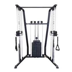
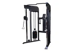
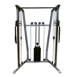
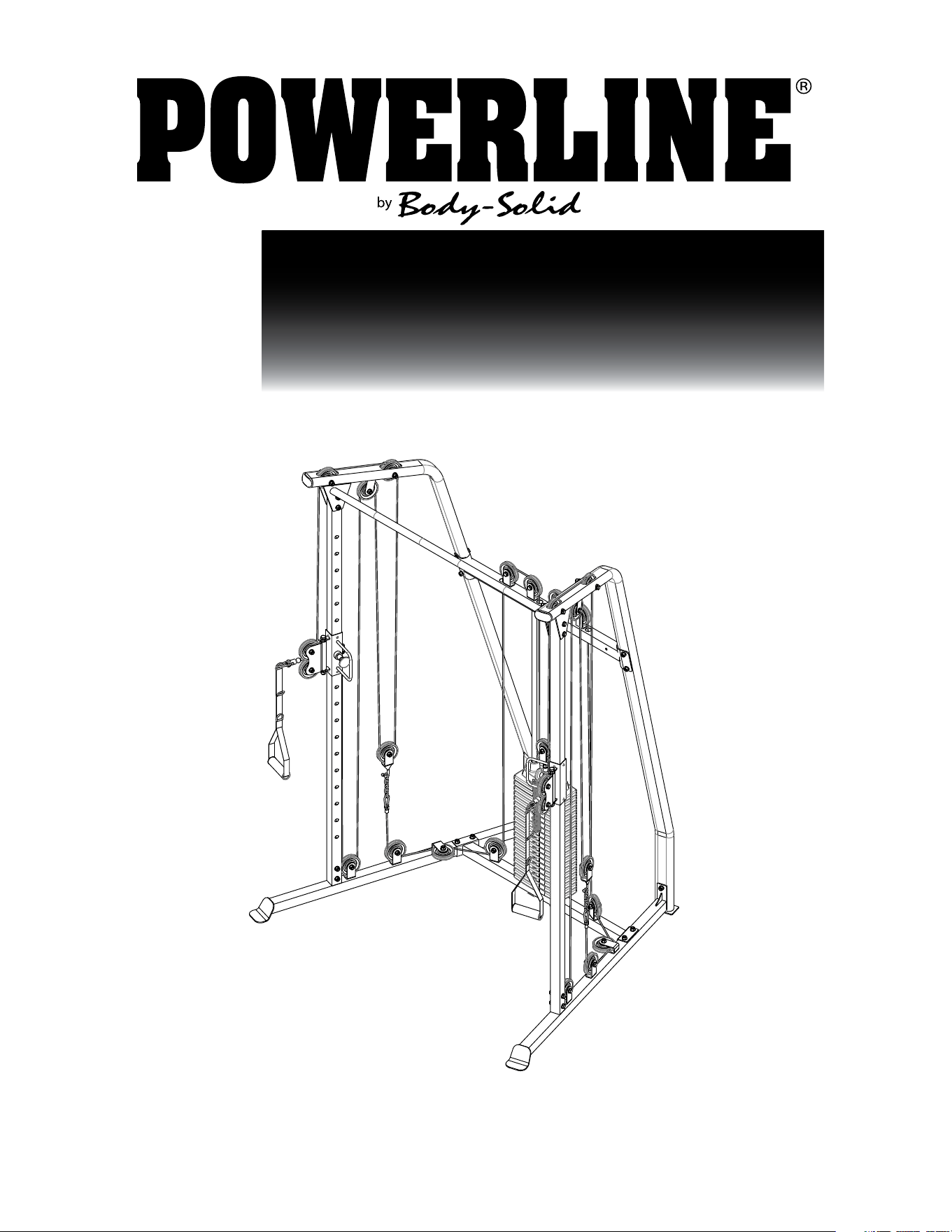
PFT50
FUNCTIONAL TRAINER
2
#DWRULE-4
#DWRULE-4

3
PFT50
TABLE OF CONTENTS
• SAFETY INSTRUCTIONS.......................
• PREPARATION.......................................
• PART/HARDWARE LIST..........................
• HARDWARE ILLUSTRATION.................
• ASSEMBLY INSTRUCTIONS.................
• EXPLODED VIEW...................................
• CONTACT PAGE.....................................
PAGE 4
PAGE 5
PAGE 6
PAGE 8
PAGE 23
PAGE 25
PAGE 26

4
PFT50
SAFETY INSTRUCTIONS
When using exercise equipment,
you should always take basic
precautions including the
following:
• ReadallinstructionsbeforeusingthePFT50.These
instructionsarewrittentoensureyoursafetyandto
protecttheunit.
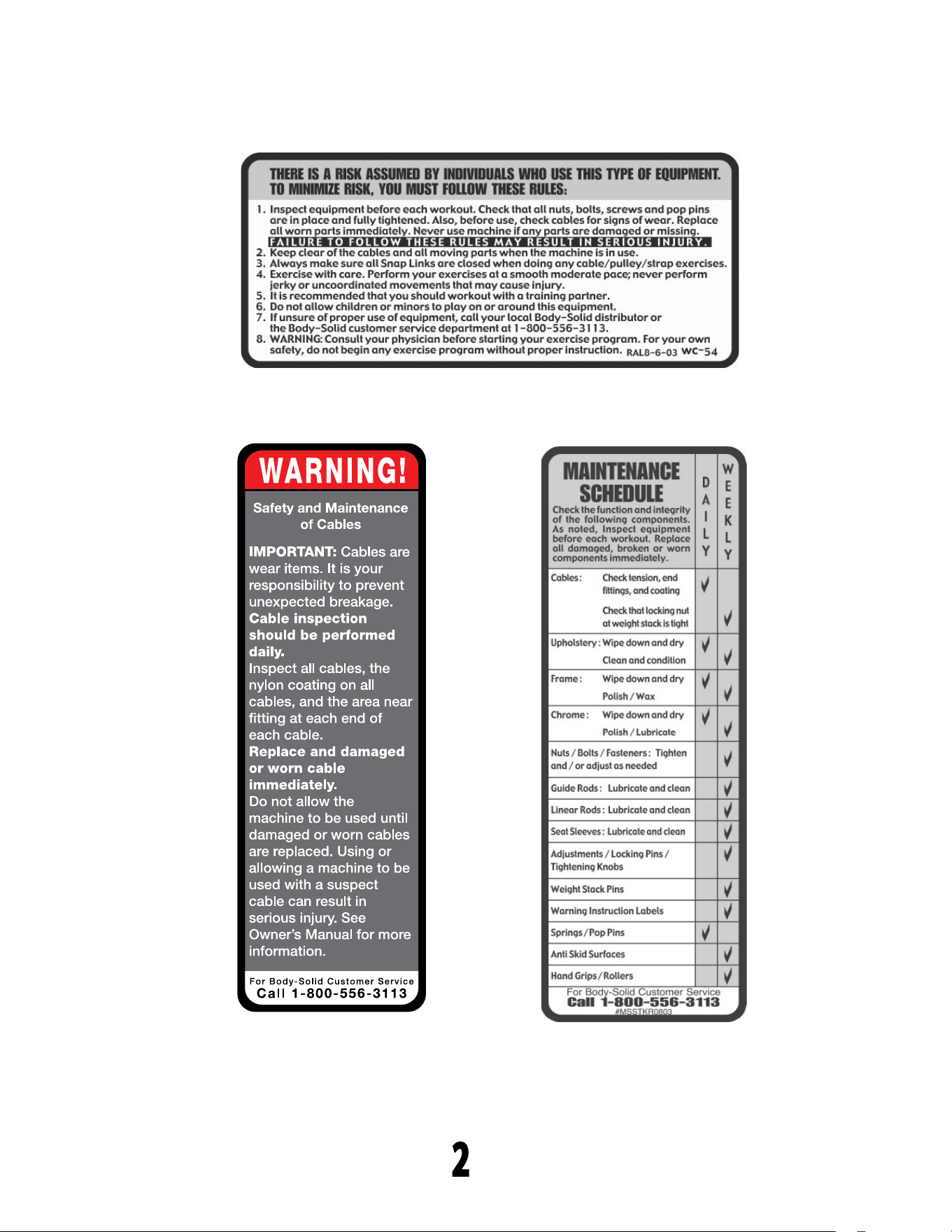
• Donotremoveanysafetylabelsfromthe
machine.
• Donotallowchildrenonorneartheequipment.
• Usetheequipmentonlyforitsintendedpurpose
asdescribedinthisguide.Donotuseaccessory
attachmentsthatarenotrecommendedbythe
manufacturer.Suchattachmentsmightcauseserious
injuries.
• Wearproperexcerciseclothingandshoesforyour
workout,nolooseclothing.
• Keephands,limbs,looseclothing,andlonghairwell
outofthewayofallmovingparts
• Usecarewhengettingonorofftheunit.
• Donooverexertyourselforworktoexhaustion.
• Ifyoufeelanypainorabnormalsymptoms,stopyour
workoutimmediatelyandconsultyourphysician.
• Neveroperateunitwhenithasbeendroppedor
damaged.Returntheequipmenttoaservicecenter
forexaminationandrepair.
• Neverdroporinsertobjectsintoanyopeninginthe
equipment.
• Alwayschecktheunitanditscablesbeforeeachuse.
Makesurethatallfastenersandcablesaresecure
andingoodworkingcondition.
• Donotusetheequipmentoutdoorsornearwater.
Personal Safety During Assembly
• Beforebeginningassembly,pleasetakethetimeto
readtheinstructionsthoroughly.
• Readeachstepintheassemblyinstructionsand
followthestepsinsequence.Donotskipahead.If
youskipahead,youmaylearnlaterthatyouhave
todisassemblecomponentsandthatyoumayhave
damagedtheequipment
• AssembleandoperatethePFT50onasolid,level
surface.Locatetheunitafewfeetfromthewallsor
furnituretoprovideeasyaccess.
ThePFT50isdesignedforyourenjoyment.Byfollow-
ingtheseprecautionsandusingcommonsense,you
willhavemanysafeandpleasurablehoursofhealthful
exercisewithyourPowerlineFunctionalTrainer.
Afterassembly,youshouldcheckallfunctionsto
ensurecorrectoperation.Ifyouexperienceproblems,
rstrechecktheassemblyinstructionstolocateany
possibleerrorsmadeduringassembly.Ifyouare
unabletocorrecttheproblem,callthedealerfrom
whomyoupurchasedthemachineorcall1-800-556-
3113forthedealernearestyou.
Obtaining Service
PleaseusethisOwner’sManualtomakesurethat
allpartshavebeenincludedinyourshipment.When
orderingparts,youmustusethepartnumberand
descriptionfromthisOwner’sManual.Useonly
PowerlinebyBodySolidreplacementpartswhen
servicingthismachine.Failuretodosowillvoidyour
warrantyandcouldresultinpersonalinjury.
Forinformationaboutproductoperationor
service,checkouttheofcialPowerlinewebsite
atwww.bodysolid.comorcontactanauthorized
PowerlinedealeroraPowerlinefactory-authorized
servicecompanyorcontactBody-Solidcustomer
serviceatoneofthefollowing:
TollFree:1-800-556-3113
Phone: 1-708-427-3555
Fax: 1-708-427-3556
Email: [email protected]
Orwriteto:Body-Solid,Inc.
ServiceDepartment
1900S.DesPlainesAve.
ForestPark,IL60130USA
Retain this Owner’s Manual for
furture reference. Part numbers
are required when ordering parts.
PFT50
PREPARATION
Required tools
Thebasictoolsthatyoumustobtainbeforeassembling
thePFT50includebutarenotlimitto:
•StandardWrenchSet
•MetricWrenchSet
•AdjustableWrench
•Standard/MetricAllenKeySet
Installation Requirements
Followtheseinstallationrequirementswhenassembling
thePFT50:
SetupthePFT50onasolid,atsurface.Asmooth,at
surfaceunderthemachinehelpskeepitlevel.
Provideamplespacearoundthemachine.Openspace
aroundthemachineallowsforeasieraccess.
Foraestheticpurposes,insertallboltsinthesame
directionunlessspecied(intextorillustrations)todo
otherwise.
Leaveroomforadjustments.Tightenfastenerssuchas
bolts,nuts,andscrewssotheunitisstable,butleave
roomforadjustments.Donotfullytightenfastenersuntil
instructedintheassemblystepstodoso.
Filloutandmailthewarrantycard.
Ordering Replacement Parts
Ifyouneedtoorderreplacementpartspleasebe
preparedtoprovidethefollowinginformation
whencontactingussothatwecanassistyoubetter.
1.ModelNumber
2.PlaceofPurchase
3.SerialNumber(S/N)
4.Part#andDescription
Assembly Tips
Readall“Notes”oneachpagebeforebeginningeachstep.
WhileyoumaybeabletoassemblethePFT50usingthe
illustrationsonly,importantsafetynotesandothertipsmaybe
includedinthetext.
Somepiecesmayhaveextraholesthatyouwillnotuse.Use
onlythoseholesindicatedintheinstructionsandillustrations.
NOTE: Withsomanyassembledparts,proper
alignmentandadjustmentiscritical.While
tighteningthenutsandbolts,besuretoleave
roomforadjustments.
NOTE: Thebottlesthataremarked“Poison”isyour
touchuppaint.Keepawayfromchildren.
CAUTION:Obtainassistance!Ifyoufeellikeyoucan’t
assemblethePFT50byyourselfthendo
notattempttodosoasthiscouldresultin
injury.ReviewtheInstallationRequirements
beforeproceedingwiththefollowingsteps.
5
↑
YOUR S/N # CAN
BE FOUND HERE

PFT50
PART LIST
6
Part #
A
B
C
D
E
F
G
H
Y
J
K
L
M
N
p
1
2
3
4
5
6
7
8
9
10
11
13
14
15
16
17
QTY
1
1
1
2
1
2
1
1
2
2
2
2
1
1
1
2
4
8
1
2
4
2
25
1
2
2
16
2
2
2
2
DESCRIPTION
LEFT LOWER BEAM
RIGHT LOWER BEAM
BASE FRAME
CHROME UPRIGHT
LEFT UPPER UPRIGHT
LOWER UPRIGHT
SUPPORT BEAM
LAT BAR
GUIDE ROD
HANDLE
DOUBLE PULLEY HOLDER
SINGLE PULLEY HOLDER
PULLEY BRACKET
SELECTOR ROD
RIGHT UPPER UPRIGHT
PULL PIN
BUSHING, 25X12.5X10mm
BUSHING, 25x10.5x32mm
CABLE, 7350mm
CABLE, 6740mm
SNAP LINK
STEEL CHAIN
PULLEY
PLASTIC PLATE
SQUARE END CAP
OVAL END CAP
PLASTIC INSERT
EVA PAD, 56x96mm
RUBBER DONUT
RUBBER
HANDLE STRAP

PFT50
PART LIST
7
Part #
18
19
20
21
22
24
25
26
27
28
29
30
32
35
36
37
38
39
40
41
QTY
2
21
12
4
4
6
2
4
88
2
43
1
1
1
1
2
2
1
1
4
DESCRIPTION
M12x175mm HEX HEAD BOLT
M10x45mm HEX HEAD BOLT
M10x60mm HEX HEAD BOLT
M10x70mm HEX HEAD BOLT
M10x100mm HEX HEAD BOLT
M8x10mm SET SCREW
M6 ACORN CAP NUT
M12 WASHER
M10 WASHER
M12 NYLON LOCK NUT
M10 NYLON LOCK NUT
TOP PLATE
WEIGHT PLATE PIN
M12 HEX NUT
M12 LOCK WASHER
CLEVIS PIN
RETAINING RING
M10x45mm SOCKET HEAD CAP SCREW
M10 LOCK WASHER
M10x65mm HEX HEAD BOLT
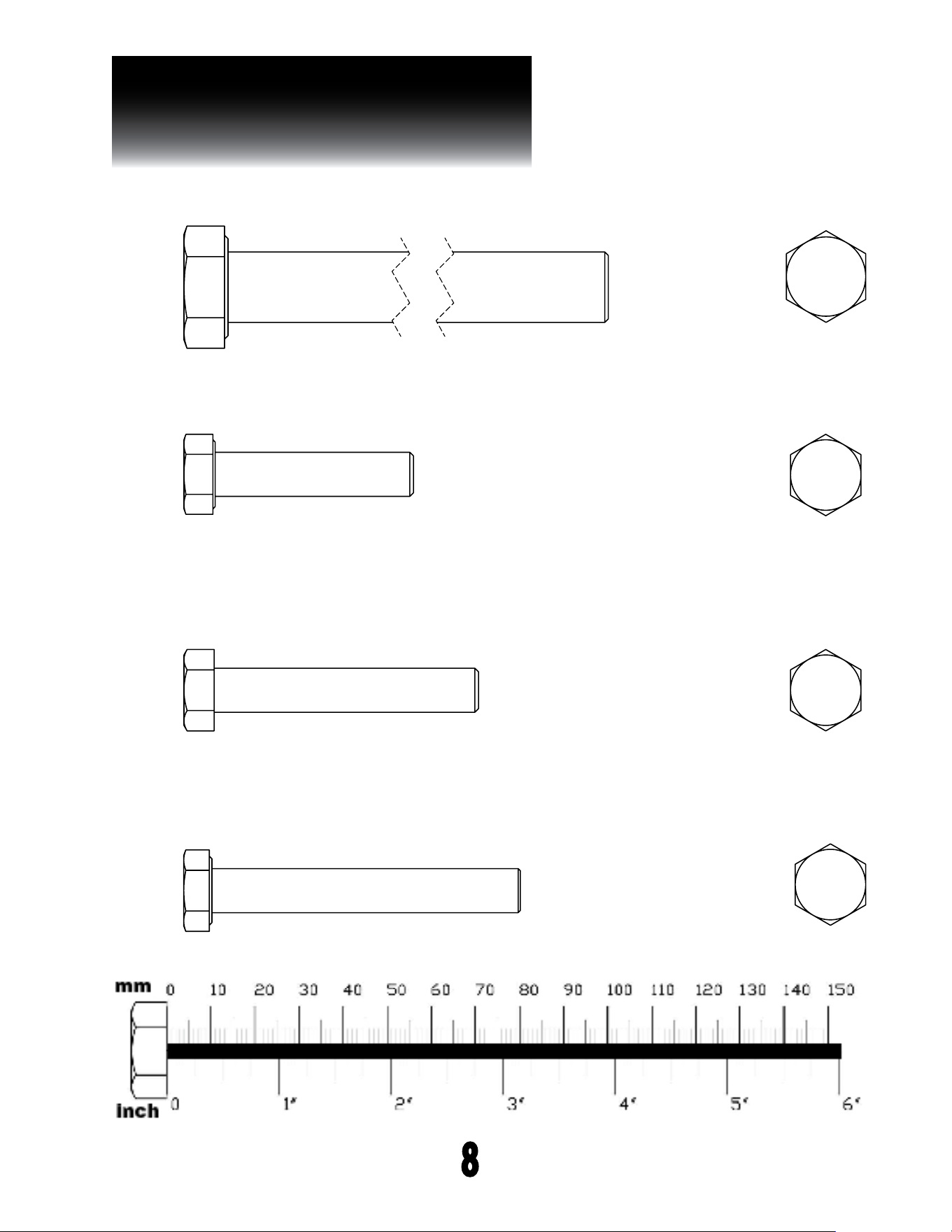
PFT50
HARDWARE ILLUSTRATION
8
Part #21 M10X70mm HEX HEAD BOLT QTY.4
Part #20 M10X60mm HEX HEAD BOLT QTY. 12
Part #18 M12x177mm HEX HEAD BOLT QTY. 2
Part #19 M10x45mm HEX HEAD BOLT QTY. 21
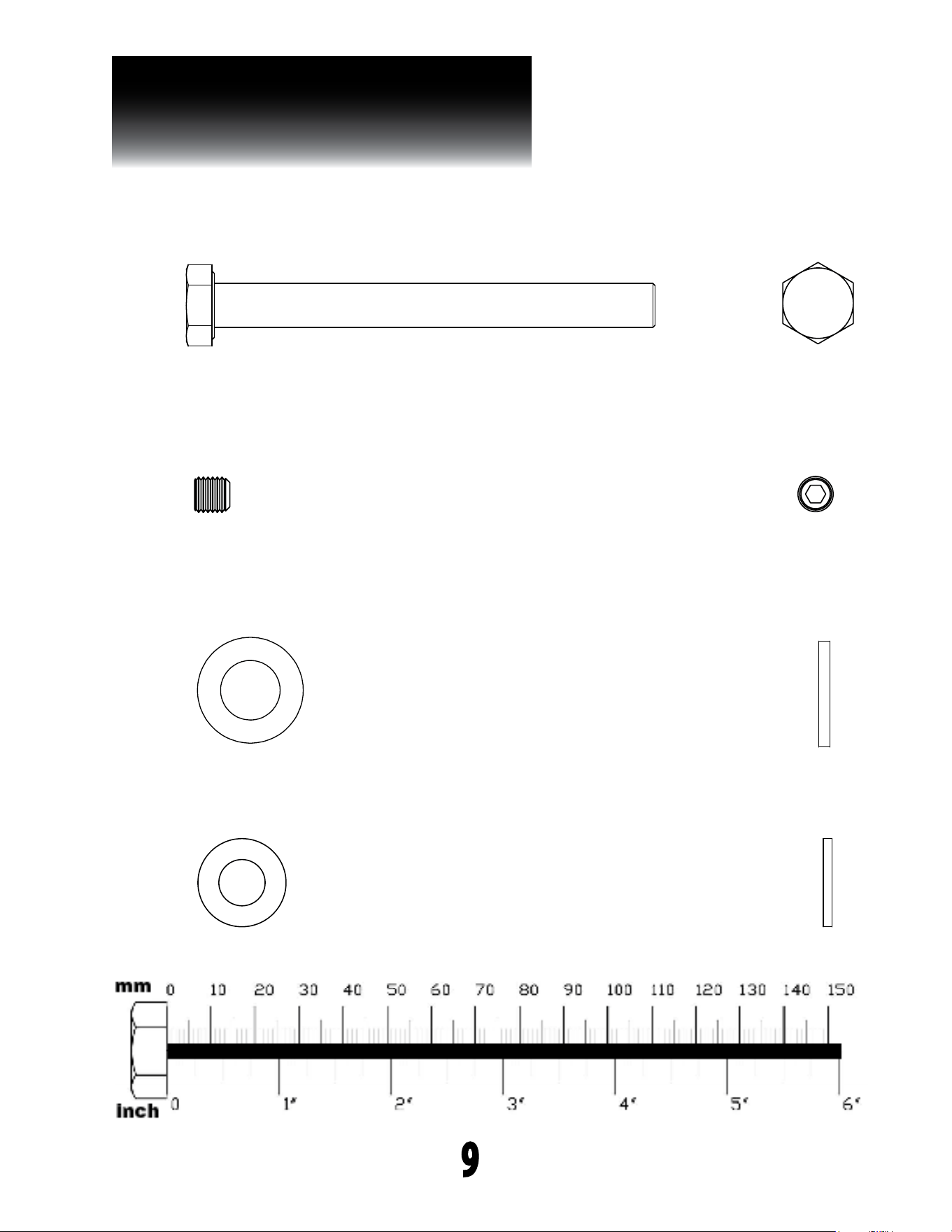
PFT50
HARDWARE ILLUSTRATION
9
Part #27 M10 WASHER QTY. 88
Part #26 M12 WASHER QTY. 4
Part #22 M10X100mm HEX HEAD BOLT QTY.4
Part #24 M8X10mm SET SCREW QTY. 6
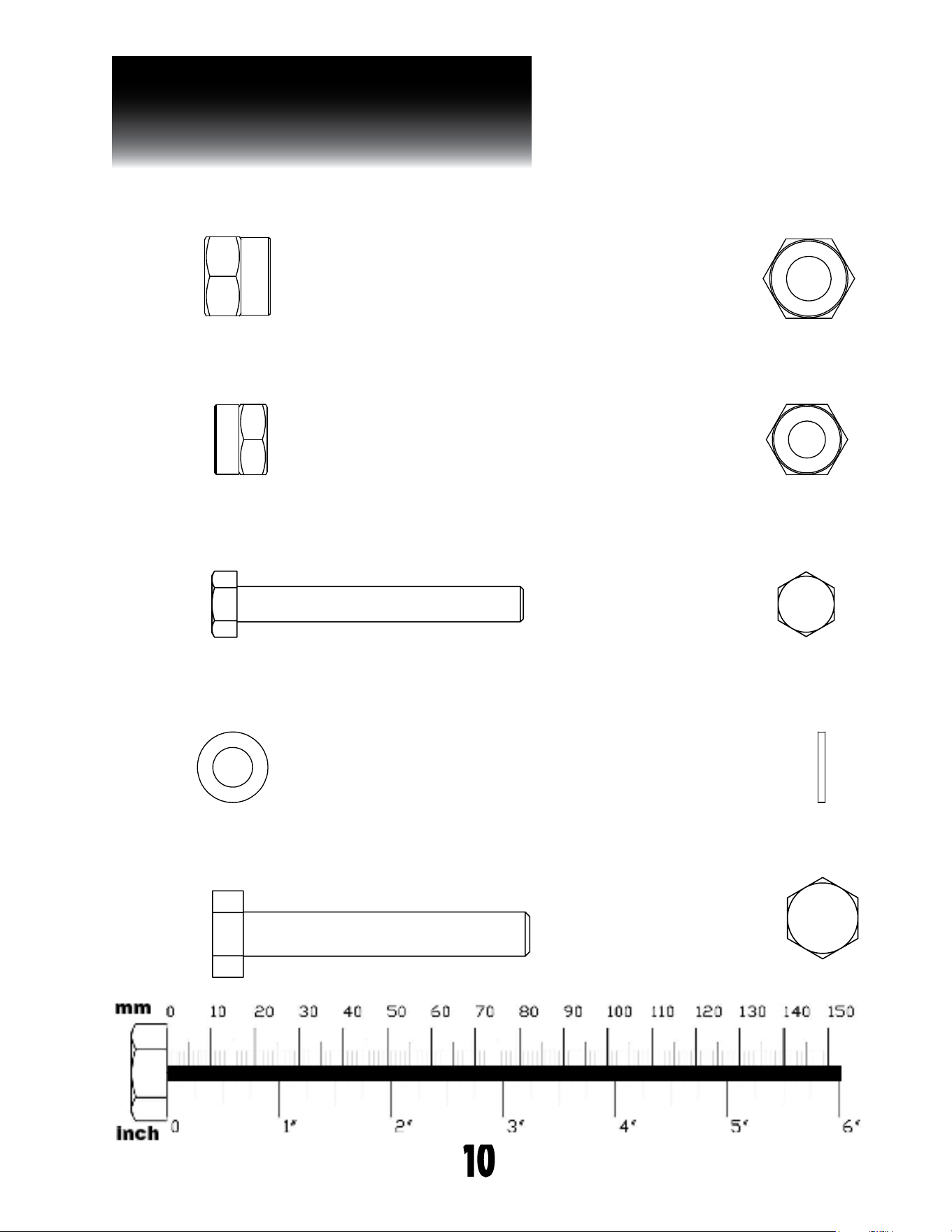
PFT50
HARDWARE ILLUSTRATION
10
Part #33 M8 WASHER QTY.4
Part #31 M8x65mm HEX HEAD BOLT QTY. 2
Part #28 M12 NYLON LOCK NUT QTY. 2
Part #29 M10 NYLON LOCK NUT QTY. 43
Part #41 M10x65mm HEX HEAD BOLT QTY. 4
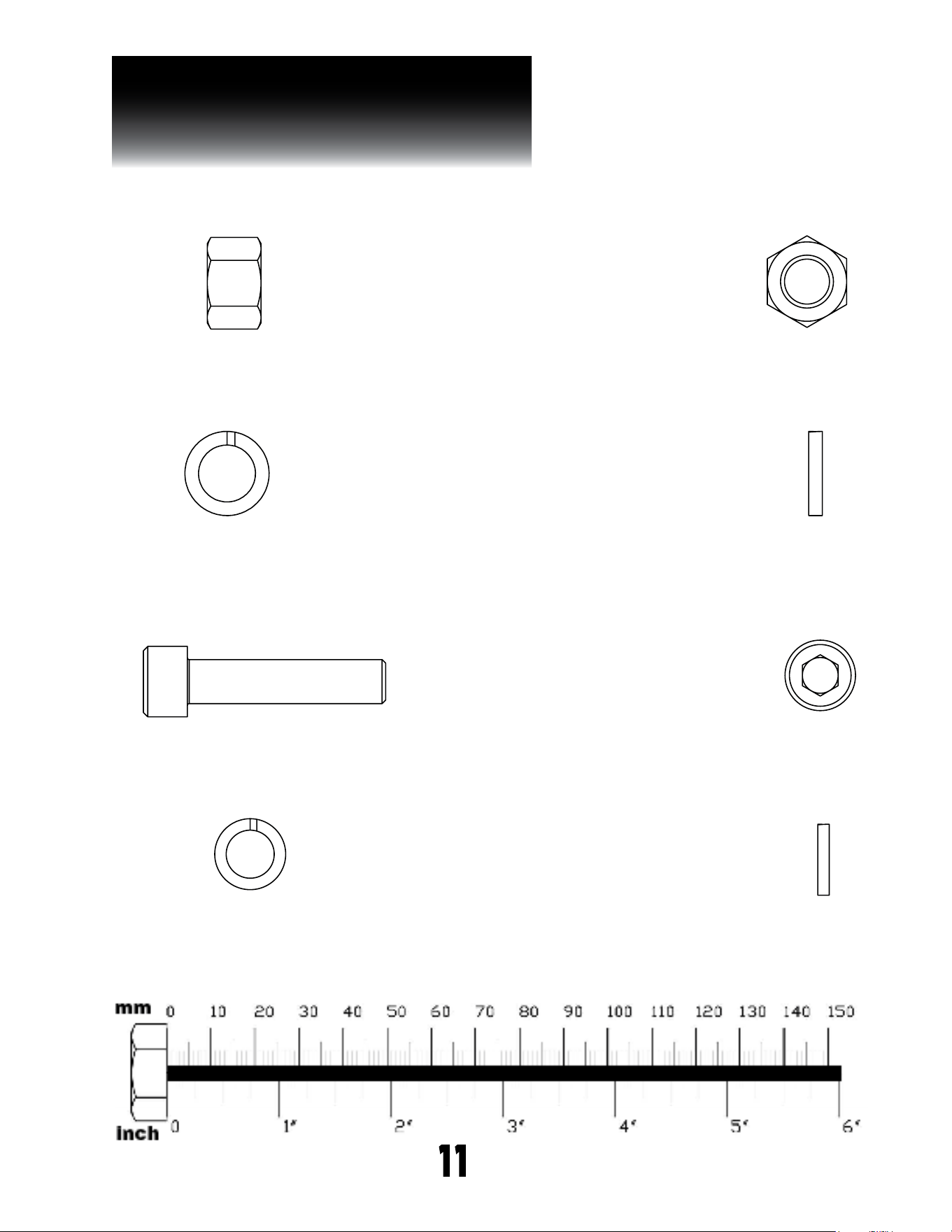
PFT50
HARDWARE ILLUSTRATION
11
Part #40 M10 LOCK WASHER QTY. 1
Part #36 M12 LOCK WASHER QTY.1
Part #39 M10x45mm SOCKET HEAD CAP SCREW QTY. 1
Part #35 M12 NUT QTY.1
UNLESS OTHERWISE SPECIFIED:
CHECKED
SIZE
APPLICATION
TITLE:
PROPRIETARY AND CONFIDENTIAL
INTERPRET GEOMETRIC
TOLERANCING PER:
Q.A.
FINISH
DWG. NO.
DATE
USED ON
A
DIMENSIONS ARE IN INCHES
TOLERANCES:
FRACTIONAL
ANGULAR: MACH
BEND
TWO PLACE DECIMAL
THREE PLACE DECIMAL
NEXT ASSY
MATERIAL
NAME
REV
DO NOT SCALE DRAWING
SCALE: 1:1
SOCKET HEAD CAP SCREW_AM
ENG APPR.
THE INFORMATION CONTAINED IN THIS
DRAWING IS THE SOLE PROPERTY OF
<INSERT COMPANY NAME HERE>. ANY
REPRODUCTION IN PART OR AS A WHOLE
WITHOUT THE WRITTEN PERMISSION OF
<INSERT COMPANY NAME HERE> IS
PROHIBITED.
COMMENTS:
DRAWN
MFG APPR.
SHEET 1 OF 1
2 1
A
B
A
B
12
<COMPANY NAME>
UNLESS OTHERWISE SPECIFIED:
CHECKED
SIZE
APPLICATION
TITLE:
PROPRIETARY AND CONFIDENTIAL
INTERPRET GEOMETRIC
TOLERANCING PER:
Q.A.
FINISH
DWG. NO.
DATE
USED ON
A
DIMENSIONS ARE IN INCHES
TOLERANCES:
FRACTIONAL
ANGULAR: MACH
BEND
TWO PLACE DECIMAL
THREE PLACE DECIMAL
NEXT ASSY
MATERIAL
NAME
REV
DO NOT SCALE DRAWING
SCALE: 1:1
SOCKET HEAD CAP SCREW_AM
ENG APPR.
THE INFORMATION CONTAINED IN THIS
DRAWING IS THE SOLE PROPERTY OF
<INSERT COMPANY NAME HERE>. ANY
REPRODUCTION IN PART OR AS A WHOLE
WITHOUT THE WRITTEN PERMISSION OF
<INSERT COMPANY NAME HERE> IS
PROHIBITED.
COMMENTS:
DRAWN
MFG APPR.
SHEET 1 OF 1
2 1
A
B
A
B
12
<COMPANY NAME>

PFT50
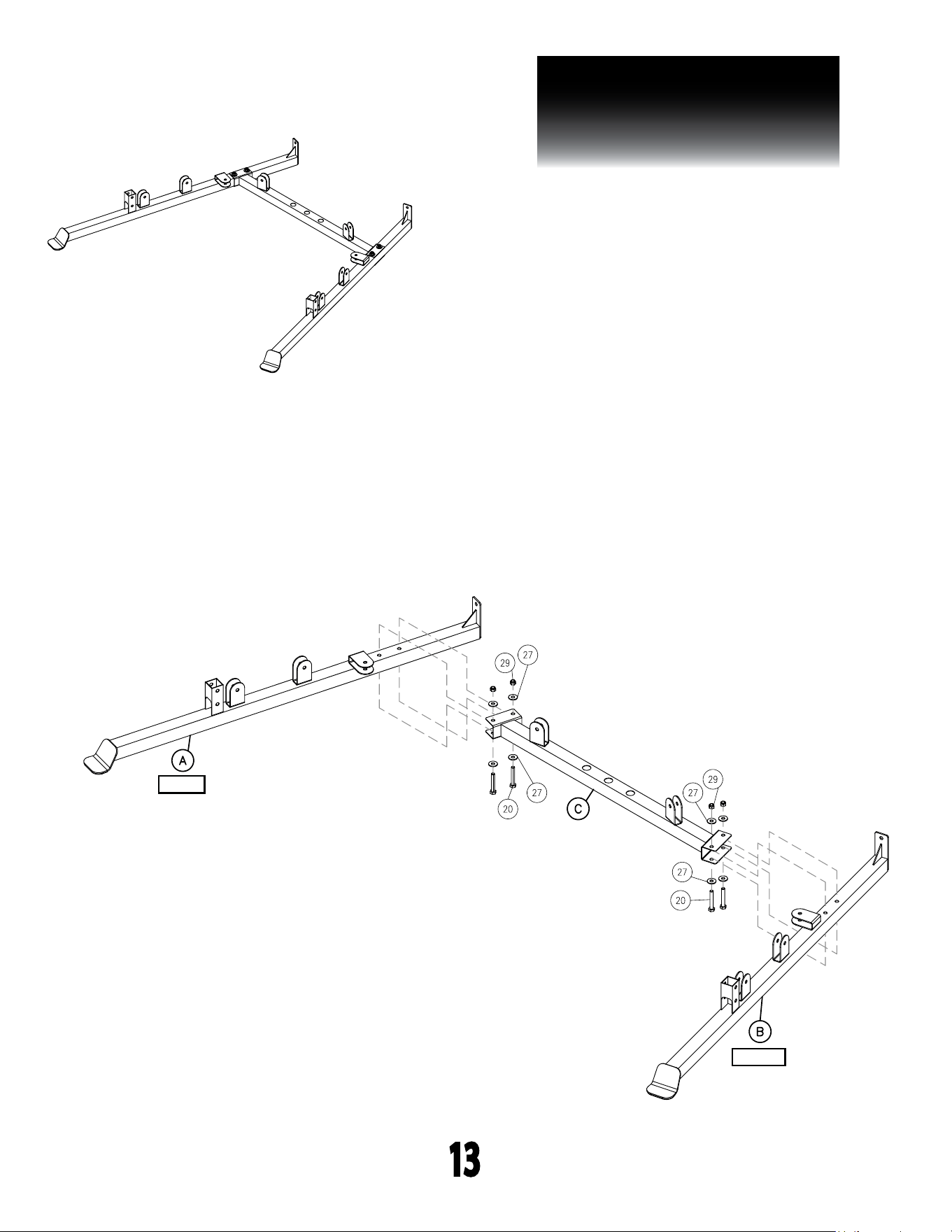
STEP 1
BE CAREFUL TO ASSEMBLE ALL COMPONENTS IN THE
SEQUENCE THAT THEY ARE PRESENTED.
NOTE:
nger tighten all hardware. some components may be pre-assembled.
1A. Attach Left Lower Beam (A) to Base Frame (C) using:
2 - (#20) M10X60mm Hex Head Bolt
4 - (#27) M10 Washer
2 - (#29) M10 Nylon Lock Nut
1B. Attach Right Lower Beam (B) to Base Frame (C) using:
2 - (#20) M10X60mm Hex Head Bolt
4 - (#27) M10 Washer
2 - (#29) M10 Nylon Lock Nut
Note: Bolt #20, M10X60mm, in this step needs to be bottom
up as shown in STEP 1 DRAWING.
12
PFT50
STEP 1
13
above shows step 1 assembled
and completed
13
s T e P
1
13
s T e P
1
LEFT
RIGHT

PFT50
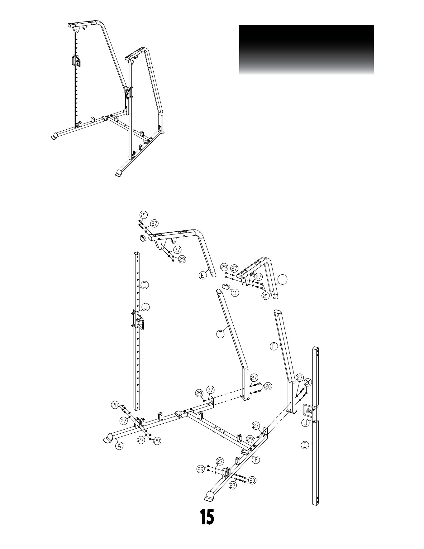
STEP 2
BE CAREFUL TO ASSEMBLE ALL COMPONENTS
IN THE SEQUENCE THAT THEY ARE PRESENTED.
NOTE:
nger tighten all hardware. some components may be pre-assembled.
2A. Attach Chrome UprightS (D) to Left & Right Lower
Beams (A & B) using:
4 - (#20) M10X60mm Hex Head Bolt
8 - (#27) M10 Washer
4 - (#29) M10 Nylon Lock Nut
2B. Slide a Handle Assembly (J) onto each Chrome Upright (D).
2C. Attach Lower Uprights (F) to Lower Beams (A & B) using
4 - (#20) M10X60mm Hex Head Bolt
6 - (#27) M10 Washer
2 - (#29) M10 Nylon Lock Nut
2D. Insert Upper Uprights (E & P) into Lower Uprights (F) and attach
Upper Uprights (E) to Chrome Uprights using
4 - (#21) M10X70mm Hex Head Bolt
8 - (#27) M10 Washer
4 - (#29) M10 Nylon Lock Nut
2E. Insert a Oval End Cap (#11) into each Upright (e & f).
14
PFT50
STEP 2
15
above shows step 2 assembled
and completed
s T e P
2
15
a
P

PFT50
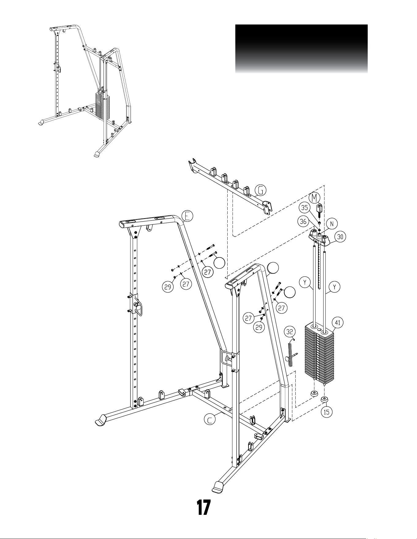
STEP 3
BE CAREFUL TO ASSEMBLE ALL COMPONENTS
IN THE SEQUENCE THAT THEY ARE PRESENTED.
NOTE:
nger tighten all hardware. some components may be pre-assembled.
3A. Install Guide Rods (Y) into the holes of the Base Frame (C).
3B. Install Rubber Donuts (#15) and slide to the bottom of the
Guide Rods (Y)
3C. Insert all Weight plates (#41) onto Guide Rods (Y)
3D. Install Top Plate (#30) & Selector Rod Assembly (N) onto
Guide Rods (Y).
3E. Install Weight Plate Pin (#32) using the key ring end through
the Pulley Bracket (M)
3F. Install M12 Hex Nut (#35), M12 Lock Washer (#36) & Pulley
Bracket (M) onto Selector Rod (N).
3G. Insert Guide Rods (Y) into Support Beam (G) and attach Support
Beam (G) to both Left & Right upper Uprights (E & P) using:
4 - (#41) M10X65mm Hex Head Bolt
8 - (#27) M10 Washer
4 - (#29) M10 Nylon Lock Nut
16
PFT50
STEP 3
17
above shows step 3 assembled
and completed
a
P
a
41
a
41

PFT50
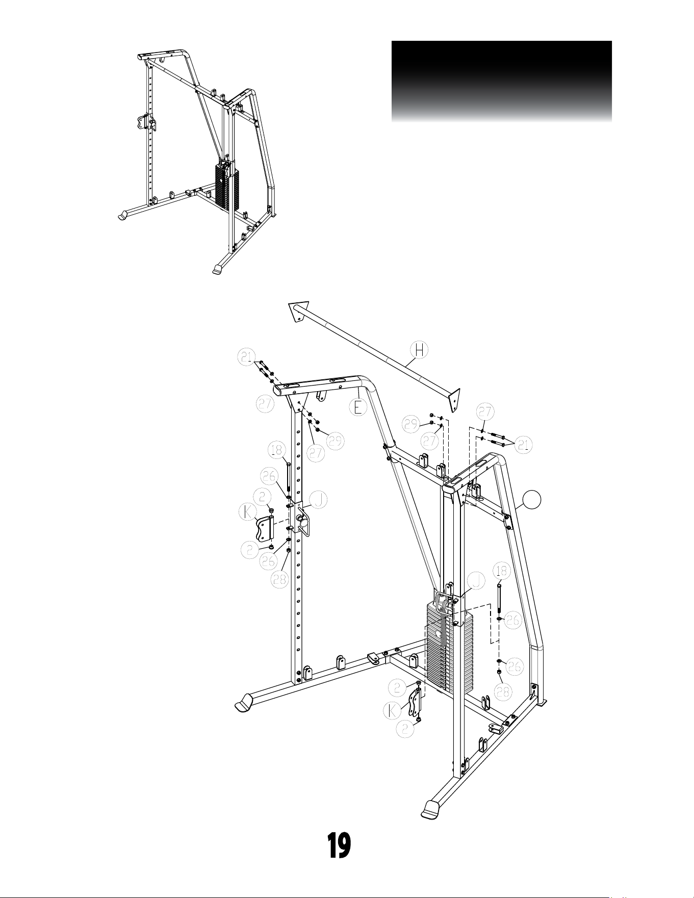
STEP 4
BE CAREFUL TO ASSEMBLE ALL COMPONENTS
IN THE SEQUENCE THAT THEY ARE PRESENTED.
NOTE:
nger tighten all hardware FIRST. wrench tighten all hardware
at the END of this step. some components may be pre-assembled.
nylon lock nuts will not fully screw onto bolts, must wrench tighten.
4A. attach Lat Bar (H) to Left & Right Upper uprights (E & P) using:
4 - (#21) M10X70mm Hex Head Bolt
8 - (#27) M10 Washer
4 - (#29) M10 Nylon Lock Nut
3B. attach Double Pulley (K) to Handle (J) on each side using:
2 - (#18) M12X175mm Hex Head Bolt
4 - (#26) M12 Washer
2 - (#28) M12 Nylon Lock Nut
4 - (#2) BUSHING
Note: Do not tighten down bolts to hard, make sure that the Double
Pulley is able to swivel.
18
PFT50
STEP 4
19
above shows step 4 assembled
and completed
a
P

PFT50
STEP 5
BE CAREFUL TO ASSEMBLE ALL COMPONENTS
IN THE SEQUENCE THAT THEY ARE PRESENTED.
NOTE:
nger tighten all hardware FIRST. wrench tighten all hardware
at the END of this step. some components may be pre-assembled.
nylon lock nuts will not fully screw onto bolts, must wrench tighten.
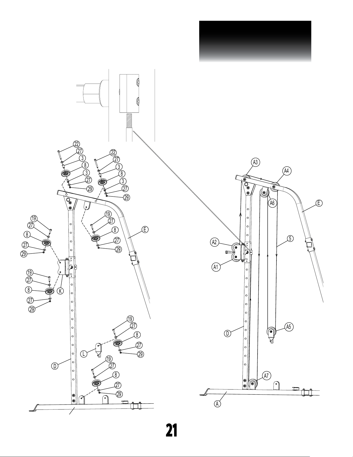
5A. Route Cable (#5) while installing Pulleys (#8) on the left side
of the machine as shown in step 5 drawing using:
5 - (#19) M10X45mm Hex Head Bolt
2 - (#22) M10X100mm Hex Head Bolt
14 - (#27) M10 Washer
7 - (#29) M10 Nylon Lock Nut
4 - (3) Bushing
5B. Repeat the previous Step (5A) on the other side of the machine.
20
PFT50
STEP 5
21
s T e P
5
21
A1
A2
A3
A4
A6 E
5
A5
A7
D
A
29
27
3
8
3
27
22
29
27
3
8
3
27
22
29
27
8
27
19
29
27
8
27
19
29
27
8
27
19
19
27
8
27
29
19
27
8
27
29
L
E
D
K
Be careful to assemble all components
in the sequence they are presented.
s T e P
8
26
NOTE: Only tighten the pulleys so that they are a little snug, over
tightening them will cause them not to rotate properly.
Cable Routing: Use a 7350mm Cable (#4). First, hook one end of the cable
onto the hook of Pulley Holder (L) that is on the left side above
Lower Left Beam (A). Second, route the cable down, under, and around
pulley C1, then over and around pulley C2, then under pulley C3 and up to
pulley C4. Third, route the cable over pulley C4 and C5 and then down
towards pulley C8. Fouth, route the cable around pulley C8, then back up
and over pulley C6 and C7. Fifth, route the cable down and around pulley
C9, then over and around pulley C10, then under pulley C11 and up to
Pulley Holder (L) that is on the right side. Lastly, hook the other end of the
cable onto the hook of Pulley Holder (L) that is on the right side.
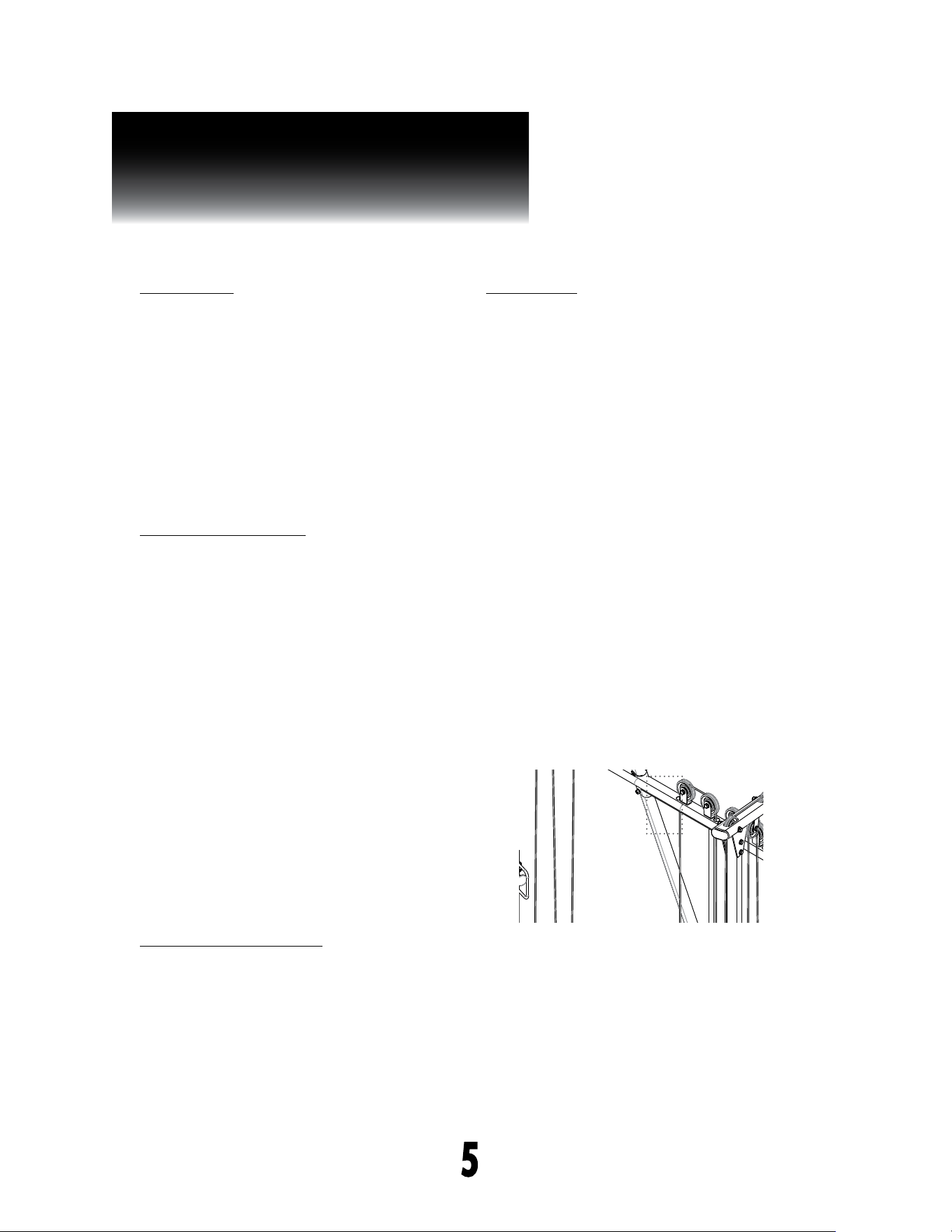
*You have completed assembling your BFFT10R machine. The last thing
you’ll need to do is tighten the cables by stripping enough plastic coating
on one side of the cable that is attached to one of the Handle Assemblies
(J). Once their is no slack left, and the coating is stripped o secure the
cable by tightening the socket set screw (#24) that is pre-installed
on Handle Assembly (J) on both the left and right side. See pic. below.
*To see the BFFT10R built live on video go to www.bodysolid.com
nOTe:
Finger tighten all hardware first. wrench tighten all pulleys at the
end of this step, some components may be pre-assembled.
nylon lock nuts will not fully screw onto bolts, must wrench tighten.
strip the plastic coating off the cable
before your tighten it down. be sure to
tighten the allen key screw as much as
possible.
↑
↑
allen key screw
(#24)

PFT50
STEP 6
BE CAREFUL TO ASSEMBLE ALL COMPONENTS
IN THE SEQUENCE THAT THEY ARE PRESENTED.
NOTE:
nger tighten all hardware FIRST. wrench tighten all hardware
at the END of this step. some components may be pre-assembled.
nylon lock nuts will not fully screw onto bolts, must wrench tighten.
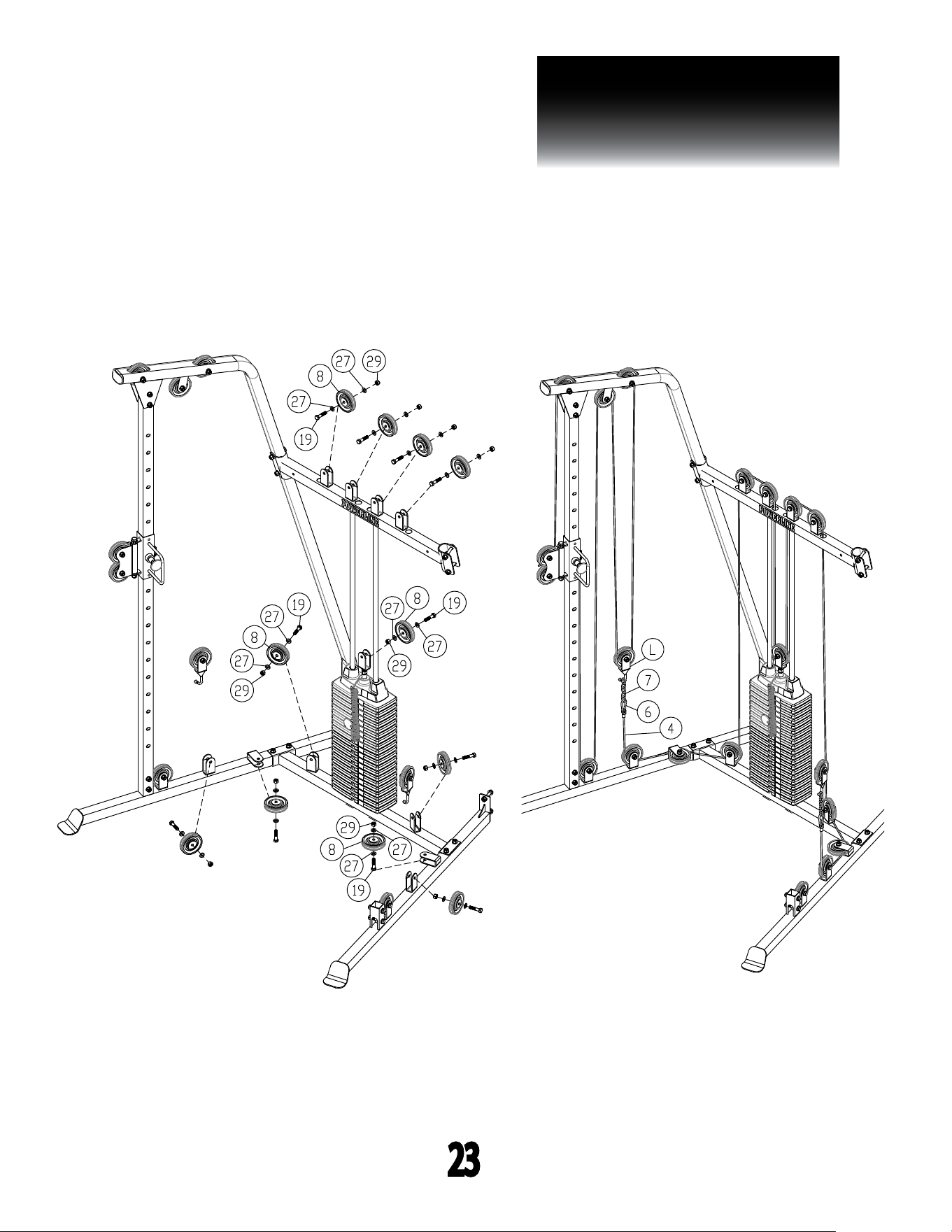
6A. Route Cable (#4) while installing Pulleys (#8) on the left side
of the machine as shown in step 6 drawing using:
11 - (#19) M10X45mm Hex Head Bolt
22 - (#27) M10 Washer
11 - (#29) M10 Nylon Lock Nut
6B. Attach Snap Link (#6) & Steel Chain (#7) to Cable (4) on each
side of the machine and then hook the other end of the Steel
chain (#7) onto each hook of the Single Pulley Holder (L).
22
PFT50
STEP 6
23

24
PFT50
NOTE
PFT50
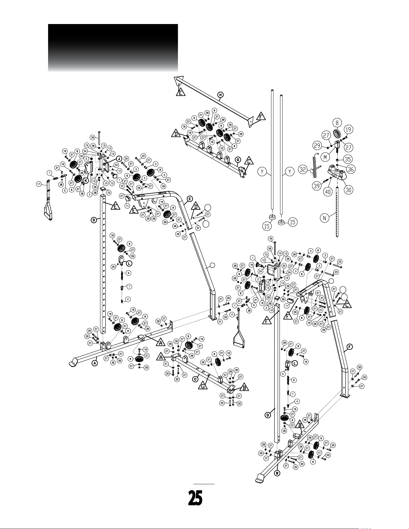
EXPLODED VIEW
25
28
eXPlODeD View DiagRaM
28
eXPlODeD View DiagRaM
P
F
41
41
41
41
41

PFT50
S/N # 016194-��-��-����-����
please write your serial number in the boxes below
1900 S. Des Plaines Ave.
Forest Park, IL 60130
Phone:(708)427-3555
Fax:(708)427-3556
Hours: M-F 8:30 - 5:00 CST