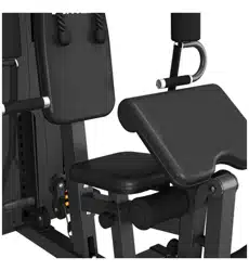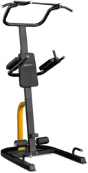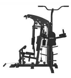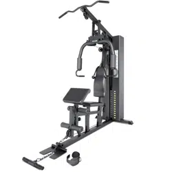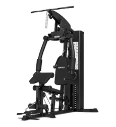
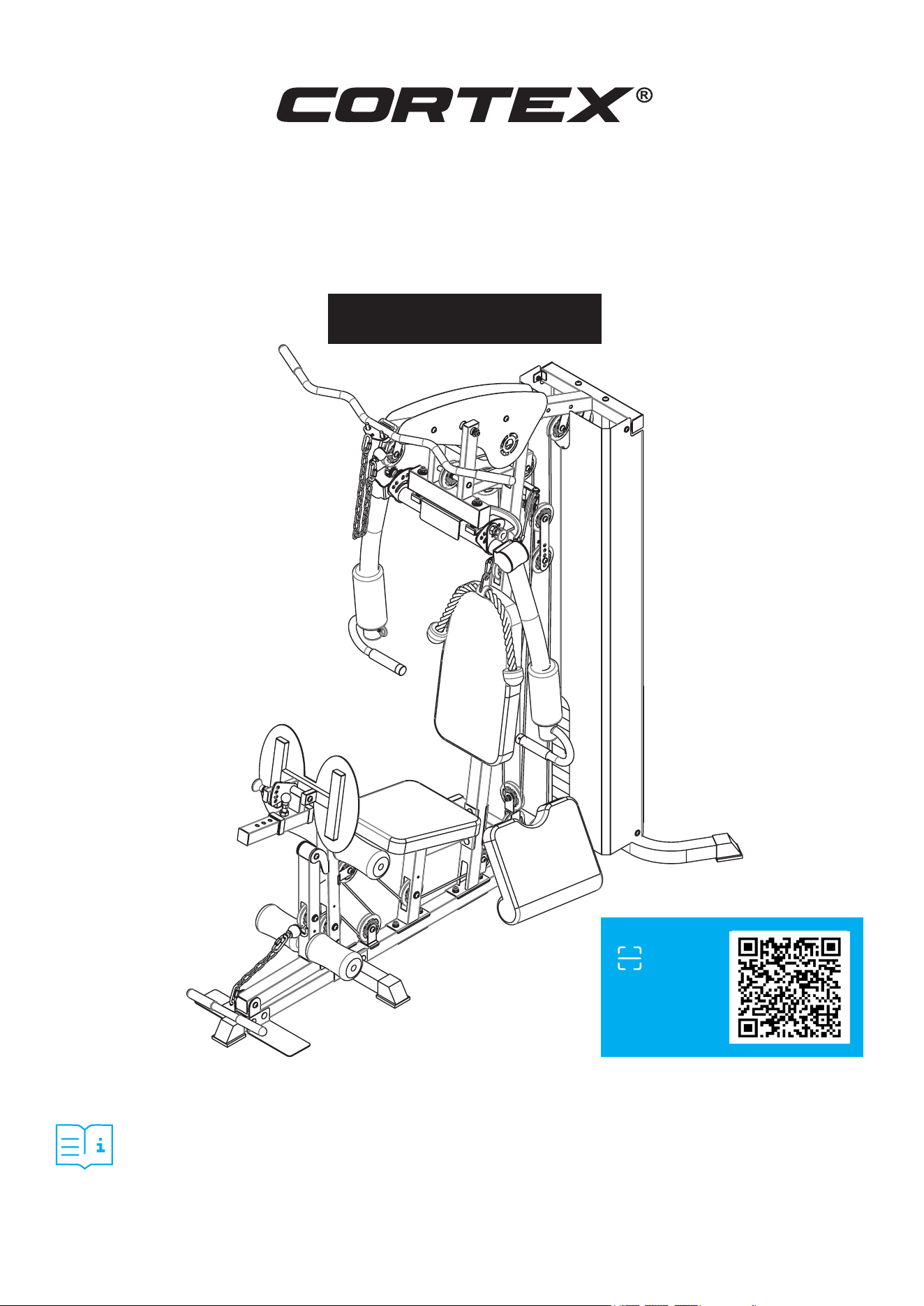
SS4 Single Station
Functional Home Gym
USER MANUAL
Product may vary slightly from the item pictured due to model upgrades.
Read all instructions carefully before using this product.
Retain this owner’s manual for future reference.
NOTE:
This manual may be subject to updates or changes. Up to date manuals are available through our
website at www.lifespanfitness.com.au
Find the
Digital Manual
Online

TABLE OF
CONTENTS
I. Important Safety Instructions . . . . . . . . . . . . . . . . . . . . . . . . . . . . . . . 03
II. Care Instructions . . . . . . . . . . . . . . . . . . . . . . . . . . . . . . . . . . . . . . . . . . . . . 04
III. Parts List . . . . . . . . . . . . . . . . . . . . . . . . . . . . . . . . . . . . . . . . . . . . . . . . . . . . . . 05
IV. Assembly Instructions . . . . . . . . . . . . . . . . . . . . . . . . . . . . . . . . . . . . . . 08
V. Maintenance . . . . . . . . . . . . . . . . . . . . . . . . . . . . . . . . . . . . . . . . . . . . . . . . . . . 21
VI. Warranty . . . . . . . . . . . . . . . . . . . . . . . . . . . . . . . . . . . . . . . . . . . . . . . . . . . . . . . 22
3
I. IMPORTANT SAFETY
INSTRUCTIONS
WARNING: Read all instructions before using this machine.
To ensure your safety, read the following precautions before using this product
1. Please read, study and understand the instructions and all warning labels before use.
(It is recommended to be familiar with the normal operation and use methods of the device before
using this product. Information is available on this manual and at local retailers).
2. Please keep this manual and ensure that all the warning labels are clear and complete.
3. This product is recommended to install by more than two people.
4. Please consult your doctor’s advice before starting the exercise.
5. Please ensure safety when the children are present.
6. Be careful when using it with children present.
7. Please check any signs of wear of the wire rope regularly. If there is wear, it may cause some danger
to you.
8. Please keep your hands, limbs and clothes stretch to use the device.
9. Please note any signs of machinery that may occur, including part wear, loose hardware, and welding
cracks. Stop using the device with the above signs immediately and contact the after-sales service
department of our company.
10. You can complete the assembly with a wrench, or an inner hexagon wrench.
11. The product is subject to change without notice, updated manuals will be available online.
12. This product is designed for indoor use, in a well ventilated room.
This product is intended for home use only. It is not designed for a commercial or public gym.
IMPORTANT SAFETY INSTRUCTIONS |
4
II. CARE INSTRUCTIONS
• Lubricate moving joints with silicon spray after periods of usage.
• Be careful not to damage plastic or metal parts of the machine with heavy or sharp objects.
• The machine can be kept clean by wiping it down using dry cloth.
• Check and adjust the tension of wire rope on a regular basis.
• Regularly check all moving parts and make sure there are signs of wear and damage, if any the use of
the device must be stopped immediately and contact our after-sales department.
• During inspection, it is necessary to make sure that all bolts and nuts are completely fixed. If any bolt
or nut connection is loosened, please re-tighten.
• Check weld for cracks.
• Failure to perform daily maintenance may result in personal injury or equipment damage.
CAUTION:
When changing accessories ensure the connection links are tightened fully. Failure to do so can
result in injury.
| CARE INSTRUCTIONS
5
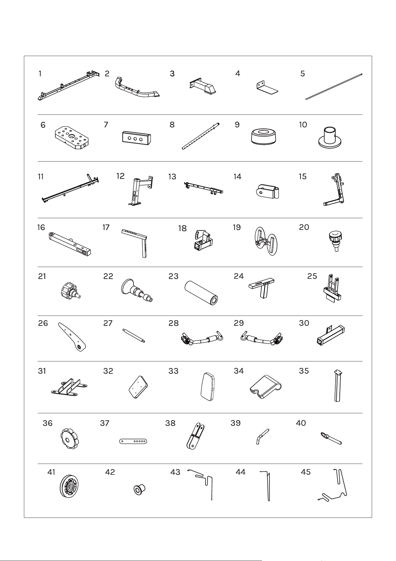
III. PARTS LIST
PARTS LIST |
Middle Ground
Piece 1x
Counterweights 12x
Stand Column 1x
Leg Arm 1x
Draw Pin - M18 2x
Decorative
panels 2x
U-Shaped Seat Cushion
Adjustment Frame 2x
M10 Knob Nut 1x
Pulley 21x Slider Liner 8x
Slide Wheel
Adjustment 2x
Cross Pulley
Frame 1x
Steel Wire Rope-
3310mm 1x
Steel Wire Rope-
3110mm 1x
Steel Wire Rope-
4900mm 1x
L-Pin 1x Round Pin 1x
Push Shaft 1x
Seat Cushion 1x
Back Cushion 1x Elbow Pad 1x Elbow Pad Tube 1x
Left Chest Fly
Arm 1x
Right Chest Fly
Arm 1x
Storage Tube 1x
Spring Pull Pin M20
(pre-installed) 1x
Rotation
Shaft-57MM 2x
Seat Adjustment
Frame 1x
Connected
Frame 1x
Leg Press
Bracket 1x
Sliding Sleeve
-Adjustment 1x
Leg Press
Plate 1x
Small-head Draw
Pin - M16 1x
Seat Support 1x
Upper Beam 1x Pulley Frame 2x
Front Bracket 2x
Counterweight
Block 1x
Selector Rod 1x
Shock-Absorbing
Pads 2x
Limit set 2x
Back Long
Ground Piece 2x
Small Side
Ground Piece 2x
Foot Tread
Plate 2x
Guide rods 2x
6 | PARTS LIST
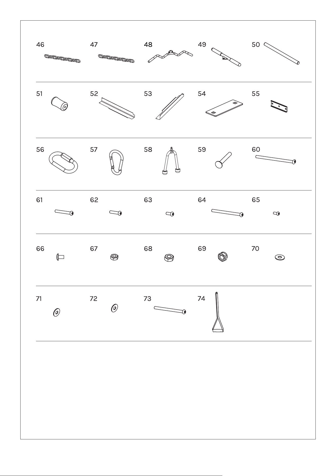
Cable handles 2x
6-Link Chain 1x
Foam 4x
Right-Side
Protective Cover 1x
C-type Buckle 4x Carabiner Clips 2x Tricep Rope 1x
Left-Side
Protective Cover 1x
110 Connecting
Plates 3x
170 Arc-Shaped
Connecting Plate 1x
Carriage bolts
M10X70 14x
Pan bolts
M10X70 6x
Cross-recessed
bolt M6X10 3x
Nut M6 3x Nut M8 6x Nut M10 45x
∅10 Enlarged
Washer 4x
∅10 Washer 90x ∅8 Washer 8x
Pan bolts
M10X45 18x
Pan bolts
M8X85 2x
Pan bolts
M10X20 12x
Pan bolts
M10X120 1x
Pan bolts
M8X16 12x
Pan bolts
M10X175 1x
15-Link Chain 1x
Curved Lat Pulldown
Handle 1x
Straight Row
Handle 1x
Foam Tube 2x
7PARTS LIST |
IV. ASSEMBLY INSTRUCTIONS
ATTENTION:
1. Place a gasket on both ends of each bolt—one beneath the bolt head and one beneath the nut—unless
otherwise specified.
2. During preliminary assembly, tighten all bolts and nuts by hand only. For final assembly, use a
wrench to fully secure all connections.
3. Certain spare parts may arrive pre-assembled from the factory.
4. It is strongly recommended that this machine be assembled by two or more people to prevent injury.
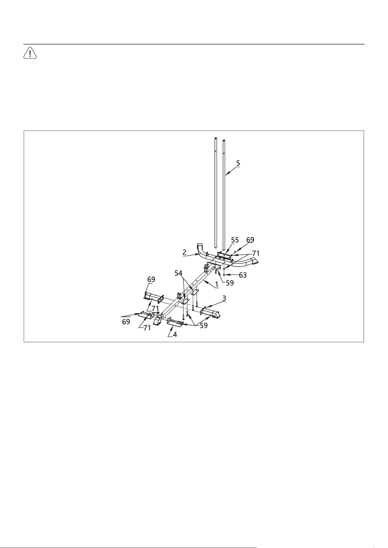
1. Lay out the following parts on a flat surface:
- Middle Ground Piece (1) x 1
- Back Long Ground Piece (2) x 1
- Small Side Ground Pieces (3) x 2
2. Connect the Ground Pieces:
a. Attach the Small Side Ground Pieces (3) to both sides of the Middle Ground Piece (1) using Carriage Bolts
M10x70 (59), Φ10 Washers (71), and M10 Nuts (69). Washers are only needed on one side for this step.
b. Hand-tighten all bolts for now.
c. Attach the Back Long Ground Piece (2) to end of the Middle Ground Piece (1) using Carriage Bolts
M10x70 (59), Arc-shaped Connecting Plate (55), Φ10 Washers (71) and M10 Nuts (69). Washers are only
needed on one side for this step.
- Foot Tread Plates (4) x 2
- 110 Connecting Plates (54) x 2
- Arc-shaped Connecting Plate (55) x 1
STEP 1
8 | ASSEMBLY INSTRUCTIONS
3. Install the Foot Tread Plates (4):
a. Position the foot tread plates on the both sides of the Middle Ground Piece (1).
b. Secure each using Carriage Bolts M10x70 (59), Φ10 Washers (71), and Nuts (69).
4. Pre-install the Connecting Plates:
a. Place the 2x 110 Connecting Plates (54) under the middle section of the frame using Carriage Bolts
M10x70 (59).
5. Insert the Guide Rods (5):
a. Insert both Guide Rods (5) into the left and right holes on Back Long Ground Piece (2).
b. Secure from underneath using Pan Bolts M10x20 (63) and Φ10 Washers (71).
6. Tighten All Bolts:
a. Once all components are correctly positioned, fully tighten all bolts with a wrench.
No. Name Qty.
1 Middle Ground Piece 1pc
2 Back Long Ground Piece 1pc
3 Small Side Ground Piece 2pcs
4 Foot Tread Plate 2pcs
5 Guide Rods 2pcs
54 110 Connecting Plates 2pcs
No. Name Qty.
55
170 Arc-Shaped Connecting
Plate
1pc
59 Carriage bolts M10X70 8pcs
63 Pan bolts M10X20 2pcs
69 Nut M10 6pcs
71 ∅10 Washer 8pcs
9ASSEMBLY INSTRUCTIONS |
No. Name Qty.
6 Counterweights 12pcs
7 Counterweight Block 1pc
8 Selector Rod 1pc
9 Shock-Absorbing Pads 2pcs
10 Limit set 2pcs
11
Stand Column
1pc
13
Upper Beam
1pc
No. Name Qty.
39 L-Pin 1pc
54 110 Connecting Plates 1pc
59 Carriage Bolts M10x70 2pcs
62 Pan Bolts M10x45 2pcs
63 Pan Bolts M10x20 2pcs
69
Nut M10
6pcs
71
∅10 Washer
10pcs
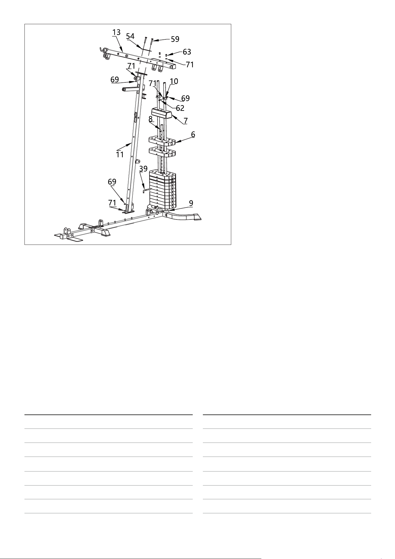
1. Install the Shock-Absorbing Pads (9):
a. Position the two pads on the Guide
Rods at the designated locations
where the weight stack will rest.
2. Assemble the Counterweights (6 &
7) and Limit Set (10):
a. Stack the Counterweights (6) one by
one onto the Shock-Absorbing Pads
(9). The pin holes must be facing down
as pictured.
b. Align the central holes to allow
smooth passage for the Selector Rod
(8). Insert the Selector Rod (8) verti-
cally through the center holes of all
counterweights.
c. Place the Counterweight Block (7) on
top of the stacked counterweights.
d. Install both Limit Sets (10) on each
side of the Guide Rods and secure
them using Pan Bolts M10x45 (62),
Washers (71), and Nuts (69). This step
only needs washer on one side.
3. Mount the Stand Column (11):
a. Fix the Stand Column (11) onto the rear section of the base frame onto the pre-installed Carriage Bolts
M10x70 (59) (from Step 1). Lock using Washers (71), and Nuts (69).
4. Install the Upper Beam (13):
a. Place the Upper Beam (13) onto the top of the Stand Column (11) and the Guide Rods.
b. Align the holes for the Stand Column (11) and connect using 110 Connecting Plate (54), Carriage Bolts
M10x70 (59), Washers (71), and Nuts (69). Washers go on both sides of bolt.
b. Align the holes for the Guide Rod and secure using Pan Bolts M10x20 (63), Washers (71), and Nuts (69).
Washer on one side only.
5. Insert the L-Pin (39):
a. Insert the L-Pin (39) through the Selector Rod (8) at the desired height to select the weight load.
6. Verify all bolts and nuts are securely tightened.
Confirm that the Selector Rod moves freely through the weight stack and that all components are stable.
STEP 2
10 | ASSEMBLY INSTRUCTIONS
No. Name Qty.
12 Seat Support 1pc
14 Pulley Frame 2pcs
30 Storage Tube 1pc
59 Carriage bolts M10X70 2pcs
61 Pan bolts M10X70 2pcs
69
Nut M10
6pcs
71
∅10 washer
8pcs
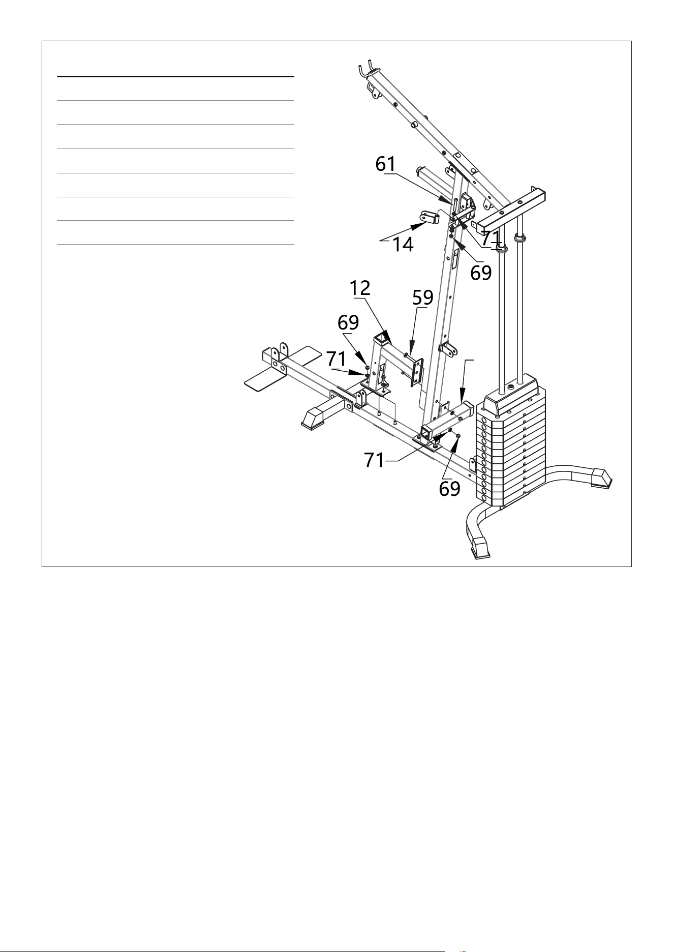
1. Attach the Seat Support (12):
a. Position the Seat Support (12) onto the pre-installed Carriage Bolts M10x70 (59) of the base frame and
secure Washers (71), and Nuts (69).
b. Hand-tighten bolts until final alignment is confirmed.
2.Attach the Storage Tube (30):
a. Mount the Storage Tube (30) onto the side of the Stand Column (11) and aligning the bolt holes with
Seat Support (12).
b. Secure both parts together using Carriage Bolts M10x70 (59), Washers (71), and Nuts (69). Washers on
one side of bolt only.
3. Install the Pulley Frames (14):
a. Align both Pulley Frames (14) with the mounting holes located on the top of Stand Column.
b. Fix in place using Pan Bolts M10x70 (61), Washers (71), and Nuts (69). Washer go on both sides of the bolt.
c. Ensure the pulleys are facing the correct direction and rotate freely.
4. Verify all parts are properly aligned and fully tightened using a wrench.
Confirm that the pulley movement is smooth and unobstructed.
STEP 3
•
30
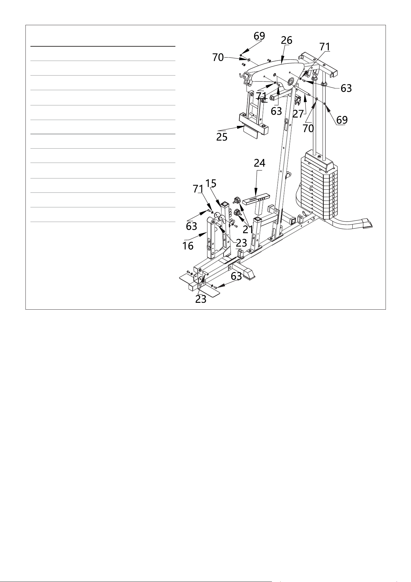
11ASSEMBLY INSTRUCTIONS |
1. Install the Front Bracket (15):
a. Insert Rotation Shaft (23) into Front Bracket (15) and position the Front Bracket (15) at the front section of the
base frame bolt holes.
b. Secure the parts using Pan Bolts M10x20 (63), Washers (71), and Nuts (69) on both sides.
c. Ensure the bracket is firmly attached and aligned with the frame.
2. Attach the Leg Arm (16):
a. Insert the Rotation Shaft (23) through the hinge holes of the Leg Arm (16), then align to bolt holes on Front Brack-
et (15).
b. Lock the shaft in place using Pan Bolts M10x20 (63) and Washers (71) on both sides.
3. Install Draw Pin (21):
a. Insert the Draw Pin – M18 (21) to the back of the Front Bracket (15). This will adjust the height of the attachments
that will be inserted into the tube.
b. Insert the second Draw Pin – M18 (21) to the side of the Seat Support and locking with Seat Adjustment Frame
(24). This is to adjust to the height of the seat.
4. Install Decorative Panels (26):
a. Attach the Decorative Panels (26) on both sides of the upper beam area using Pan Bolts M10x20 (63) and Wash-
ers (71) on both sides.
5. Install the Connected Frame (25) & Push Shaft (27):
a. Place the Connected Frame (25) to the outer sides of the Decorative Panels and align with the middle hole.
b. Connect the Push Shaft (27) through the Connected Frame (25), Decorative Panels, and Upper Beam Assembly.
c. Secure on both ends using Φ10 Enlarged Washers (70) and Nuts (69).
d. Tighten securely while ensuring free motion of the shaft.
6. Confirm all bolts, nuts, and pins are tightened securely.
STEP 4
•
•
•
No. Name Qty.
15 Front bracket 1pc
16 Leg Arm 1pc
21 Draw pin - M18 2pcs
23 Rotation shaft-57MM 2pcs
24
Seat Adjustment Frame
1pc
25
Connected Frame
1pc
26 Decorative panels 2pcs
27 Push shaft 1pc
63 Pan bolts M10X20 8pcs
69 Nut M10 2pcs
70
∅10 enlarged washer
2pcs
71 ∅10 washer
8pcs
12 | ASSEMBLY INSTRUCTIONS
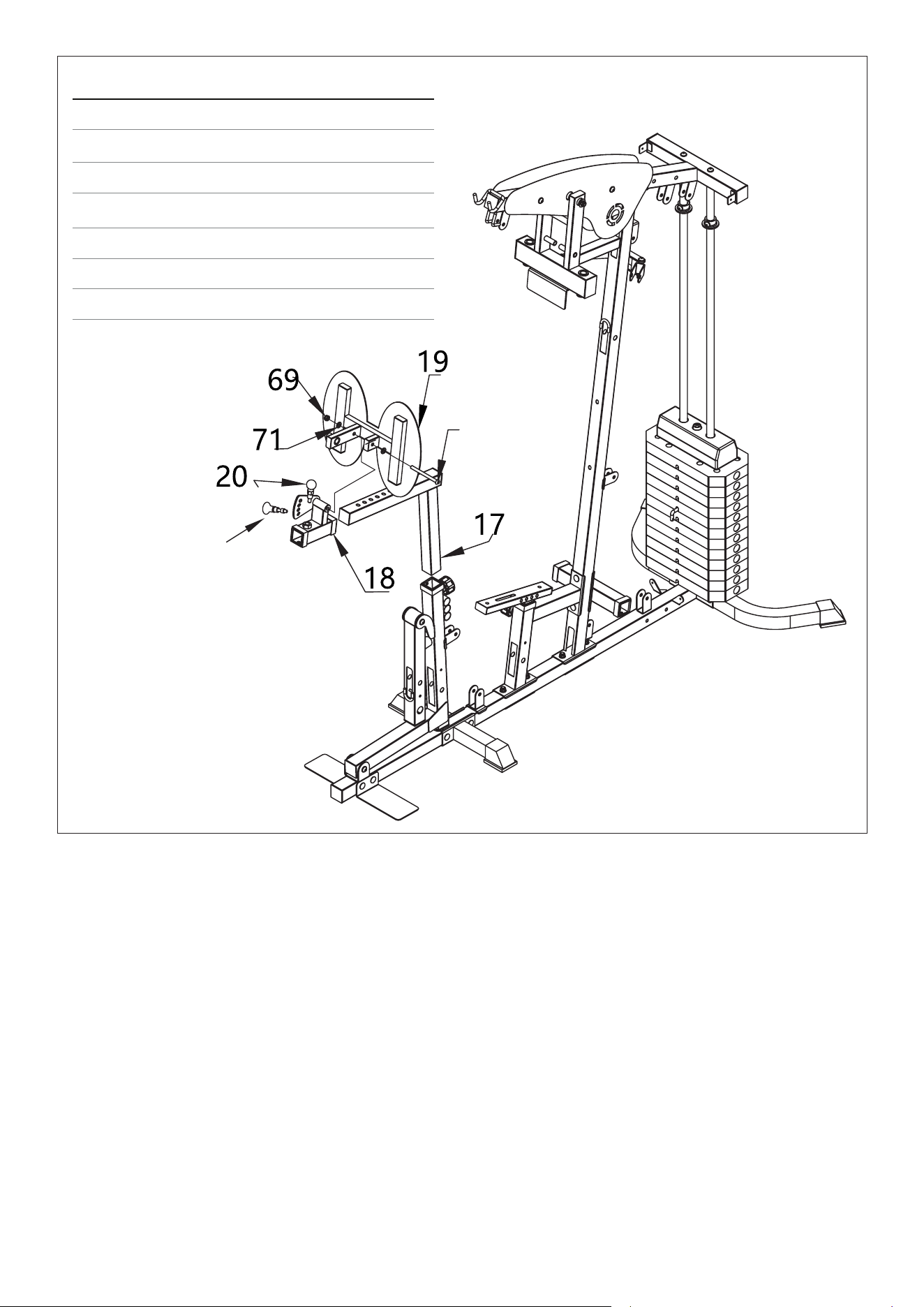
1. Attach the Leg Press Bracket (17):
A. Position the Leg Press Bracket (17) into the Front Bracket tube, aligning it with the pre-drilled mounting holes
and lock using the Draw Pin (21).
2. Install the Sliding Sleeve – Adjustment (18):
a. Remove the pre-installed Spring Pull Pin (22) from the Leg Press Bracket.
b. Slide the Adjustment Sleeve (18) onto the Leg Press Bracket (17) and secure using the Small-Head Draw Pin–M16 (20).
3. Attach the Leg Press Plate (19):
a. Align holes and connect the Leg Press Plate (19) to Sliding Sleeve – Adjustment (18) using Pan Bolt M10x120 (64),
Φ10 Washers (71) and Nut M10 (69). Washers go on both sides.
b. Secure the Spring Pull Pin (22) through the Leg Press Plate and Adjustment Sleeve (18).
4. Tighten all bolts while confirming the plate can rotate freely for natural leg movement.
5. During exercise: Adjust the height and positions using the Draw Pins and Spring Pull Pin. Ensure the pins are
fully engaged and locked after changing positions.
Storage: When this is not in use, the Leg Press Bracket can be removed and stored in the Storage Tube.
STEP 5
No. Name Qty.
17 Leg Press Bracket 1pc
18 Sliding Sleeve -Adjustment 1pc
19 Leg Press Plate 1pc
20 Small-Head Draw Pin - M16 1pc
69 Nut M10 1pc
71
∅10 washer
2pcs
64
Pan bolts M10X120
1pc
64
•
22
13ASSEMBLY INSTRUCTIONS |
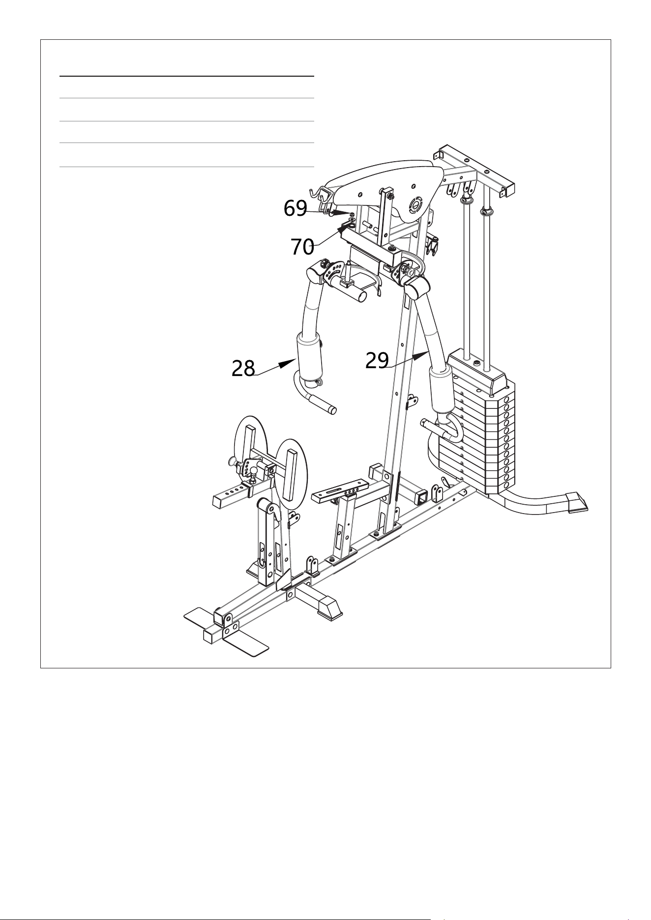
1. Attach the Left Chest Fly Arm (28):
a. Position the Left Chest Fly Arm (28) on the left side of the Upper Beam Assembly, aligning it with the mounting
holes.
b. Insert the pivot bolt through the arm and secure it using a Φ10 Enlarged Washer (70) and Nut M10 (69).
c. Ensure the arm can rotate smoothly on its pivot point.
2. Attach the Right Chest Fly Arm (29):
a. Repeat the same procedure for the Right Chest Fly Arm (29) on the opposite side.
b. Insert the bolt through the pivot and secure with a Φ10 Enlarged Washer (70) and Nut M10 (69).
3. Confirm both arms move symmetrically and without resistance.
STEP 6
No. Name Qty.
28 Left Chest Fly Arm 1pc
29 Right Chest Fly Arm 1pc
69 Nut M10 2pcs
70 ∅10 Enlarged Washer 2pcs
14 | ASSEMBLY INSTRUCTIONS
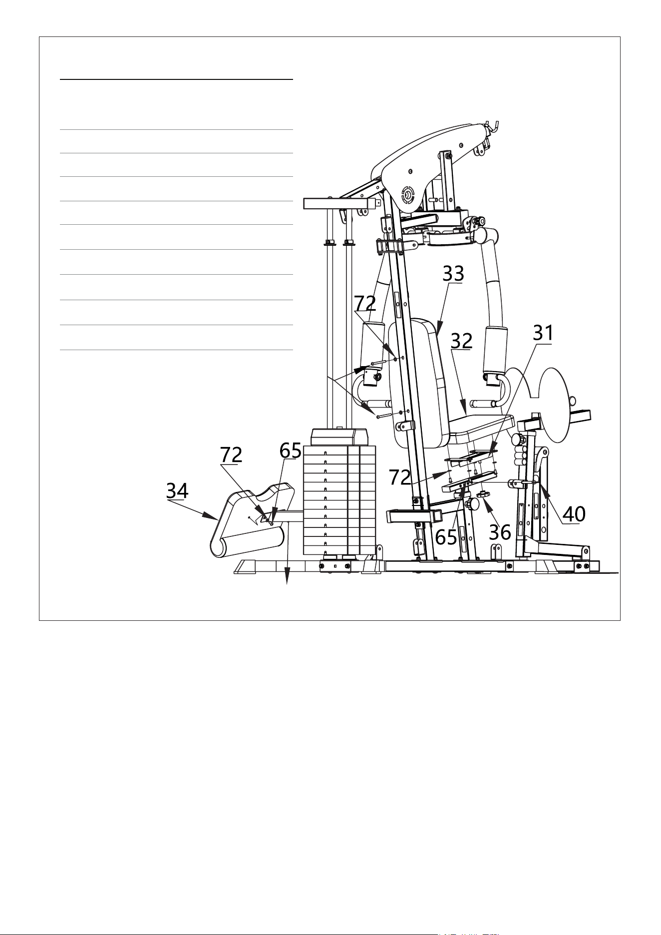
1. Attach the Seat Cushion (32):
a. Position the Seat Cushion (32) onto the Adjustment Frame (31) and fasten with Pan Bolts M8x6 (65) and
Washers (72) from underneath.
2. Install the U-Shaped Seat Cushion Adjustment Frame (31):
a. Align the Seat Adjustment Frame (31) to the side hole of Seat Adjustment Frame then secure using Round Pin (40).
b. Secure the seat underneath using M10 Knob Nut (36).
c. During exercise: The seat can be adjusted fore/backward using the Round Pin and Knob Nut to secure into place.
3. Mount the Preacher Pad (34):
a. Fix the Preacher Pad (34) on top of the Preacher Pad Tube (35) using Pan Bolts M8×16 (65) and Washers (72).
b. During exercise: The Preacher Pad can be placed into the Front Bracket to use for bicep curls.
Storage: When not in use the Preacher Pad Tube can be placed into the Storage Tube.
STEP 7
73
35
No. Name Qty.
31
U-Shaped Seat
Cushion Adjustment
Frame
1pc
32 Seat Cushion 1pc
33 Back Cushion 1pc
34 Preacher Pad 1pc
35 Preacher Pad Tube 1pc
36 M10 knob nut 1pc
40 Round Pin 1pc
65 Pan bolts M8x16 6pcs
72 ∅8 Washer 8pcs
73 Pan bolts M8x85 2pcs
15ASSEMBLY INSTRUCTIONS |
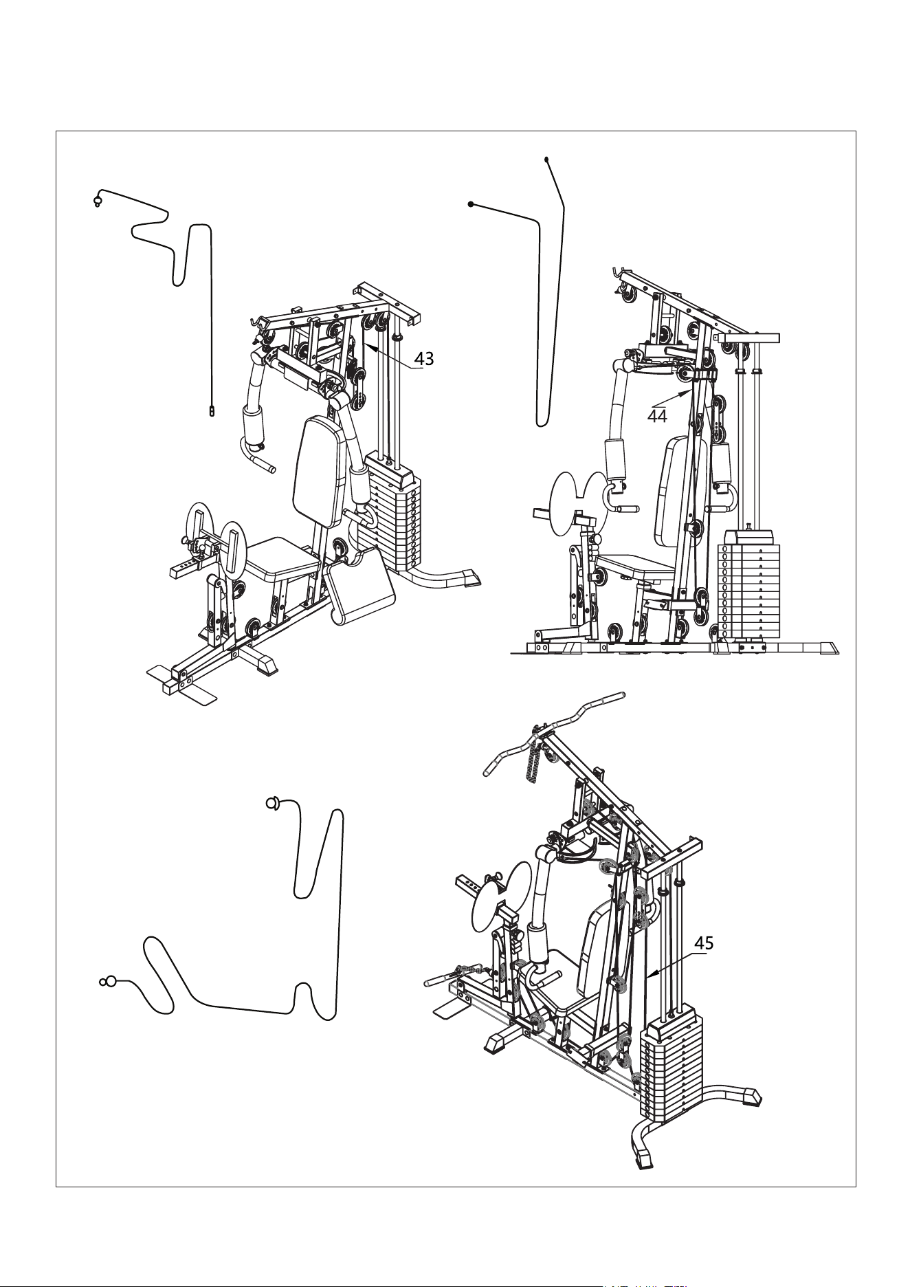
CABLE DIAGRAMS
Note: Thread the steel wire rope through first before installing the pulley
Cable 43
Cable 44
Cable 45
16
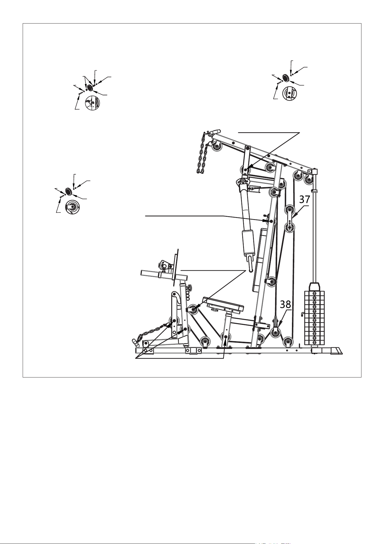
1 Section labelled in the diagram is
assembled in the following order:
60/71/41/71/69
* Refer to the Cable diagram for direction of the cables.
* Place the ropes into the pulley before securing the pulley to the frame.
1. Install Cable 43:
a. Starting from the top side - the first 2 pulley are installed using the parts 62/71/ 41/71/69.
b. On the third pulley located on the Connected Frame (25), install using parts 60/71/41/71/69.
c. Forth pulley on the Stand Column (11) is installed using parts 62/71/41/71/69.
d. Fifth pulley: Use Slide Wheel Adjustment (37) to hold the pulley on the outside and mount with the
same formation as previous step parts 62/71/ 41/71/69.
e. The last 2 pulleys are mounted to the frame in the same formation using parts 62/71/41/71/69.
f. The bolt end of the cable is then screwed into the selector rod.
STEP 8
| ASSEMBLY INSTRUCTIONS
60/71/41/71/69
69
69
69
71
71
71
71
71
71
61
60
62
41
41
41
42
61/71/42/41/42/71/69
61/71/42/41/42/71/69
62/71/41/71/69
All other sections of the pulley are
assembled in the following order:
62/71/41/71/69
4 Sections labelled in the diagram
is assembled in the following order:
61/71/42/41/42/71/69

17ASSEMBLY INSTRUCTIONS |
2. Install Cable 44:
a. Starting from the left side, hook the cable to the back of the left chest fly arm.
b. Place the first pulley into the Pulley Frame (14) on the left side and secure in order parts
62/71/41/71/69.
c. Next, use Cross Pulley Frame (38) to secure the the pulley in order of parts 62/71/41/71/69. Leave this
part to hang.
d. Route the cable to the right side Pulley Frame (14) and secure in order parts 62/71/41/71/69.
e. Lastly, hook the cable to the back of the right side chest fly arms.
3. Install Cable 45:
a. Start from the bottom using the ball end of the cable, secure the pulley to the Leg Arm (16) in the order
parts 61/71/42/41/42/71/69.
b. Onto the next pulley, place this into the centre post of Front Bracket (15) and secure in order parts
61/71/42/41/42/71/69.
c. Third pulley is secured to the Middle Ground Piece (1) in the order parts 62/71/41/71/69.
d. Forth pulley is secured to the back of Front Bracket (15) using parts 62/71/41/71/69.
e. Fifth pulley is secured to Seat Support (12) using parts 61/71/42/41/42/71/69.
f. The next pulley is assembled in the Middle Ground Piece (1) in the order parts 62/71/41/71/69.
g. For the seventh pulley, attach it to Cross Pulley Frame (38) using 62/71/41/71/69.
h. Attach the next pulley to the last pulley frame on Middle Ground Piece (1) in order of parts
62/71/41/71/69.
i. Next moving to the top and installing to Slide Wheel Adjustment (37), secure in order parts
62/71/41/71/69. Secure this loosely for now as you may need to adjust the cord length later.
j. Next, route the cord the pulley frame at back of Stand Column (11) and secure in order parts
62/71/41/71/69.
k. Last pulley is attached to the pulley frame within Stand Column (11) using parts 61/71/42/41/42/71/69.
4. Final check:
a. Check the cable tightness and adjust on Slide Wheel Adjustment (37).
b. Check all bolts are tightened. If cables are not running smoothly, readjust the cables and loosen the
bolt slightly as it may be too tight. Apply some lubrication on the pulleys if required.
No. Name Qty.
37 Slide Wheel Adjustment 2pcs
38 Cross Pulley frame 1pc
41 Pulley 21pcs
42 Slider Liner 8pcs
60 Pan bolts M10x175 1pc
61 Pan bolts M10x70 4pcs
62 Pan bolts M10x45 16pcs
69 Nut M10 21pcs
71 ∅10 Washer 42pcs
18
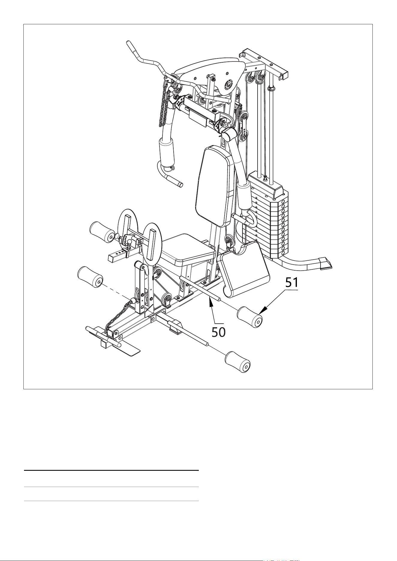
1. Install Foam Rollers
a. Place the Foam Tubes (50) into the holes on Leg Arm (16) and either 3x holes on Front Bracket (16).
The 3 holes are to suit different user heights.
b. Slot the Foams (51) onto the end of the rods.
STEP 9
No. Name Qty.
50 Foam Tube 2pcs
51 Foam tube 4pcs
19
13
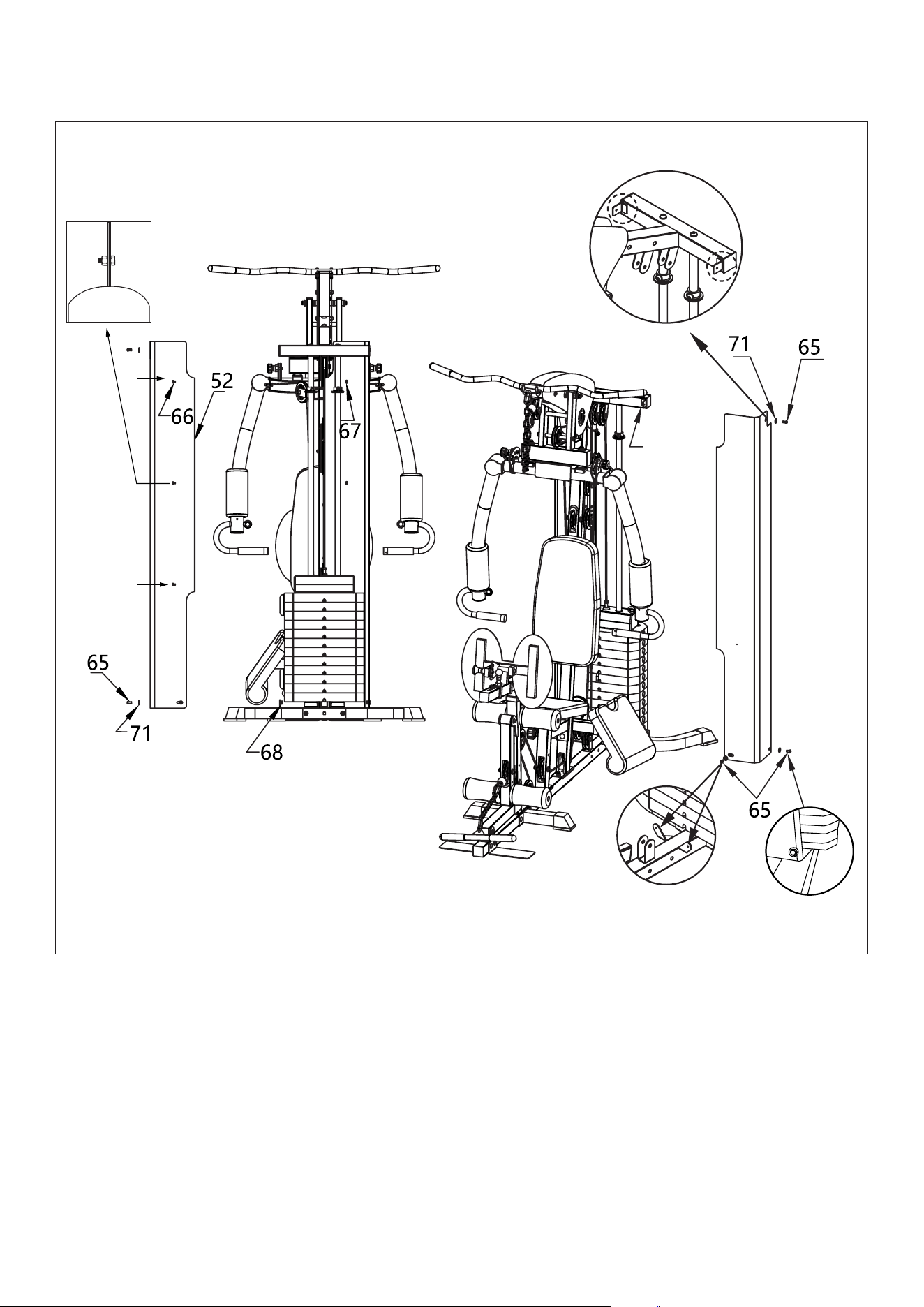
STEP 10
1. Join the Covers R/L
a. Join the Left and Right Cover (52 & 53) together where the cut out hole is using Cross-recessed Bolt
M6x10 (66) and Nut M6 (67). It does not matter which way the bolt faces. See Fig. 4.
2. Attach Covers R/L to frame
a. Secure Left Side Cover (53)on the sides of Stand Column (13) and Back Long Ground Piece (2) using
Pan Bolts M8x16 (65), Washer (71) and Nut M8. See Fig. 1 and Fig. 3 images.
Repeat the same steps for the Right Side Cover (52).
Fig. 1
Fig. 2
Fig. 4
Fig. 3

20
No. Name Qty.
52 Right-side Protective Cover 1pc
53 Left-side Protective Cover 1pc
65 Pan Bolts M8x16 6pcs
66 Cross-Recessed Bolt M6X10 3pcs
No. Name Qty.
67 Nut M6 3pcs
68 Nut M8 6pcs
71
∅10 Washer
6pcs
b. At the front side of both covers secure to the Middle Ground Piece (1) using Pan Bolts
M8x16 (65), Washer (71) and Nut M8. See Fig. 2.
3. Final Check: Check all the screws are tightened properly.
Cable attachments:
* Chains (46 & 47): The chains are used for gym attachments to elongate the cables. Use the C-type
buckle (56) to attach them to the cable rings.
* Tricep rope (58)/ Straight row handle (49)/ Curl lat pulldown bar (48)/ Cable Handles (74): Attach these
to the Cables or the Chains using the C-type buckle (56) or Carabiner Clips (57).
Note: Cable Handles (74) can also be attached to the Chest Fly Arm Handles
where there is a round hoop.

21
V. MAINTENANCE
MAINTENANCE METHOD:
To extend the service life of the device, the parts must be lubricated on time. The product has been
initially lubricated before leaving the factory, but lubrication is required between the guide rod and
the weight plate over time.
1. Pulley and wire ropes should be regularly checked for signs of wear.
2. Check and adjust the tension of the wire rope regularly.
3. Check all moving parts regularly. If there is a damaged part, stop using the device immediately and
contact the store.
4. Ensure all bolts and nuts are fully fixed and re-tighten them when it is loose.
5. Check the welding for cracks.
6. Failure to perform routine maintenance may cause personal injury or equipment damage.
7. Ensure any handle attachments are fully secured before use to prevent from injury.
NOTE: Silicon oil/spray is recommended for lubrication.
MAINTENANCE |
22| WARRANTY
VI. WARRANTY
AUSTRALIAN CONSUMER LAW
Many of our products come with a guarantee or warranty from the manufacturer. In addition, they come
with guarantees that cannot be excluded under the Australian Consumer Law. You are entitled to a
replacement or refund for a major failure and compensation for any other reasonably foreseeable loss
or damage.
You are entitled to have the goods repaired or replaced if the goods fail to be of acceptable quality and
the failure does not amount to a major failure. Full details of your consumer rights may be found at
www.consumerlaw.gov.au.
Please visit our website to view our full warranty terms and conditions:
http://www.lifespanfitness.com.au/warranty-repairs
WARRANTY AND SUPPORT
Any claim against this warranty must be made through your original place of purchase.
Proof of purchase is required before a warranty claim may be processed.
If you have purchased this product from the Official Lifespan Fitness website, please visit
https://lifespanfitness.com.au/warranty-form
For support outside of warranty, if you wish to purchase replacement parts or request a repair or
service, please visit https://lifespanfitness.com.au/warranty-form and fill in our Repair/Service
Request Form or Parts Purchase Form.
Scan this QR code with your device to go to lifespanfitness.com.au/warranty-form


WWW.LIFESPANFITNESS.COM.AU