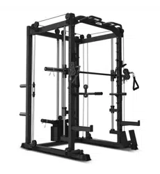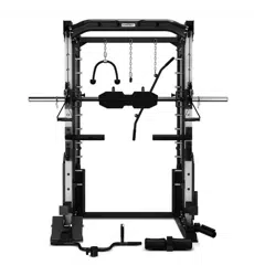
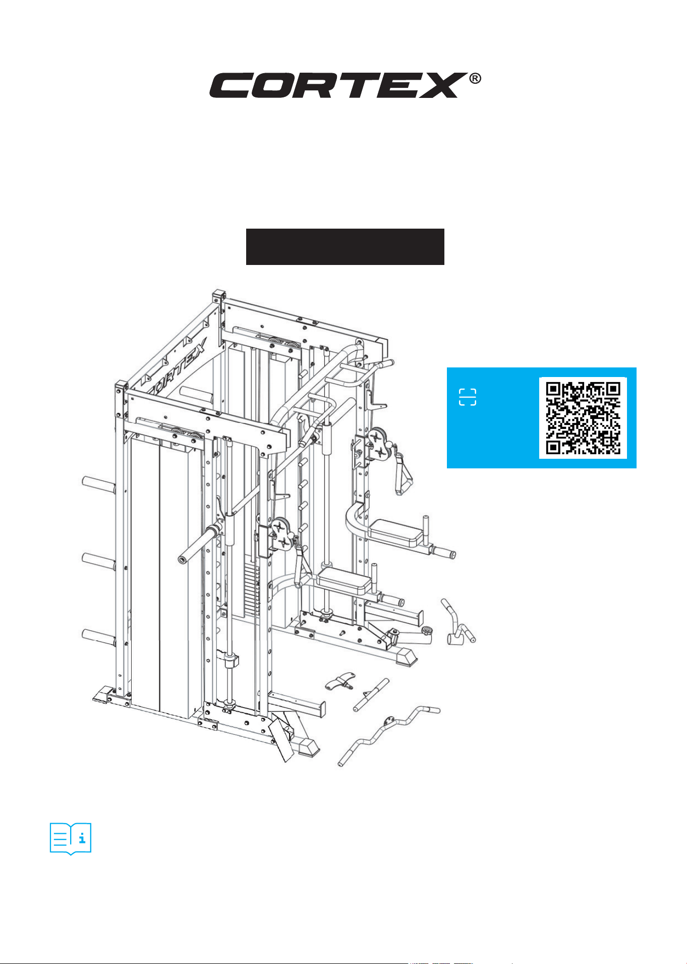
SM26 Multi Gym
(Dual Stack Functional Trainer,
Smith Machine, Half Rack)
USER MANUAL
Product may vary slightly from the item pictured due to model upgrades.
Read all instructions carefully before using this product.
Retain this owner’s manual for future reference.
NOTE:
This manual may be subject to updates or changes. Up to date manuals are available through our
website at www.lifespanfitness.com.au
Find the
Digital Manual
Online

2
TABLE OF
CONTENTS
I. Important Safety Instructions . . . . . . . . . . . . . . . . . . . . . . . . . . . . . . . 03
II. Care Instructions . . . . . . . . . . . . . . . . . . . . . . . . . . . . . . . . . . . . . . . . . . . . . 04
III. Parts List . . . . . . . . . . . . . . . . . . . . . . . . . . . . . . . . . . . . . . . . . . . . . . . . . . . . . . 05
IV. Assembly Instructions . . . . . . . . . . . . . . . . . . . . . . . . . . . . . . . . . . . . . . 09
V. Exercise Guide . . . . . . . . . . . . . . . . . . . . . . . . . . . . . . . . . . . . . . . . . . . . . . . . 24
VI. Maintenance . . . . . . . . . . . . . . . . . . . . . . . . . . . . . . . . . . . . . . . . . . . . . . . . . . . 25
VII. Warranty . . . . . . . . . . . . . . . . . . . . . . . . . . . . . . . . . . . . . . . . . . . . . . . . . . . . . . 26
| TABLE OF CONTENTS

3IMPORTANT SAFETY INSTRUCTIONS |
I. IMPORTANT SAFETY
INSTRUCTIONS
WARNING: Read all instructions before using this machine.
To ensure your safety, read the following precautions before using this product
1. Please read, study and understand the instructions and all warning labels before use.
(It is recommended to be familiar with the normal operation and use methods of the device before
using this product. Information is available on this manual and at local retailers).
2. Please keep this manual and ensure that all the warning labels are clear and complete.
3. This product is recommended to install by more than two people.
4. Please consult your doctor’s advice before starting the exercise.
5. Please ensure safety when the children are present.
6. Be careful when using it with children present.
7. Please check any signs of wear of the wire rope regularly. If there is wear, it may cause some danger
to you.
8. Please keep your hands, limbs and clothes stretch to use the device.
9. Please note any signs of machinery that may occur, including part wear, loose hardware, and welding
cracks. Stop using the device with the above signs immediately and contact the after-sales service
department of our company.
10. You can complete the assembly with a wrench, or an inner hexagon wrench.
11. The product is subject to change without notice. Updated manuals are posted on our website.

4 | CARE INSTRUCTIONS
II. CARE INSTRUCTIONS
• Lubricate moving joints with silicon spray after periods of usage.
• Be careful not to damage plastic or metal parts of the machine with heavy or sharp objects.
• The machine can be kept clean by wiping it down using dry cloth.
• Check and adjust the tension of wire rope on a regular basis.
• Regularly check all moving parts and make sure there are signs of wear and damage, if any the use of
the device must be stopped immediately and contact our after-sales department.
• During inspection, it is necessary to make sure that all bolts and nuts are completely fixed. If any bolt
or nut connection is loosened, please re-tighten.
• Check weld for cracks.
• Failure to perform daily maintenance may result in personal injury or equipment damage.

5
PARTS LIST |
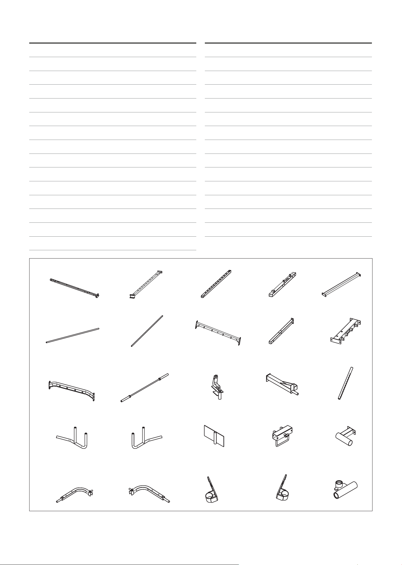
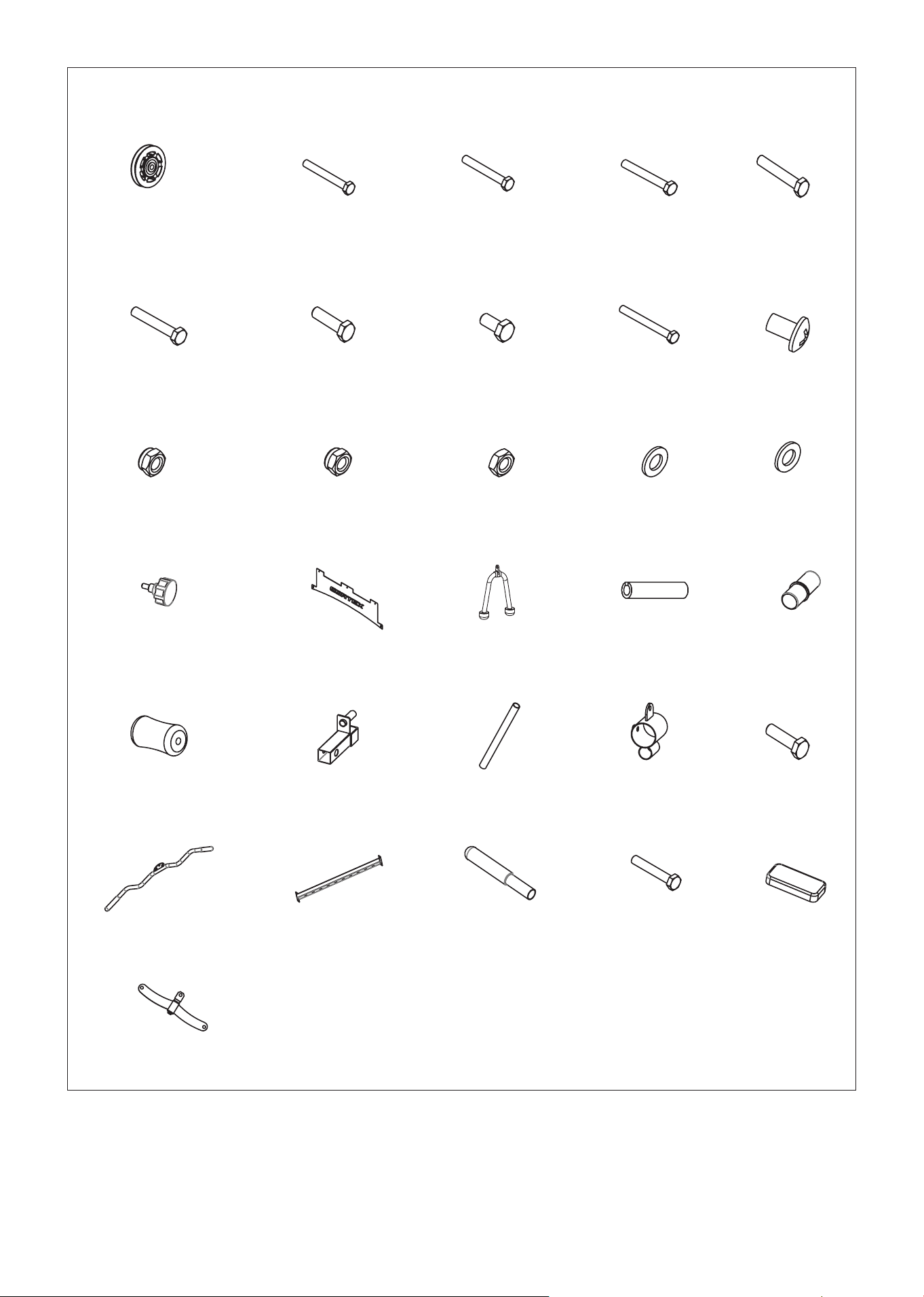
III. PARTS LIST
No. Name Qty.
1 Back Column 2
2 Central Pillar 2
3 Front Vertical Tube 2
4 Bottom Side Beams 2
5 Rear Bottom Beam 1
6 Smith Guide Rod 2
7 Stainless Steel Guide Rod 4
8 Top Rear Beam 1
9 Side Shelves 2
10 Top Side Beams 2
11 Before the Upper Beam 1
12 Smith Barbell 1
13 V-Hook 2
14 Long Protective Frame 2
15 Weight Selection Rod 2
16 Right Lead Handle 1
17 Left Lead Handle 1
18 Foot Plate 2
19 Cable Adjuster Sleeve 2
20 Olympic Barbell Holder 1
21 Dip Handle Left 1
22 Dip Handle Right 1
23 Smith Safety Bar Left 1
24 Smith Safety Bar Right 1
25 Bearing Holder 2
26 Pulley Bracket 2
27 Barrel 1
28 Landmine Handle 1
29 Curl Lat Pull Down 1
30 Low Pull Handle 1
31 Top Side Covers 4
No. Name Qty.
32 Bottom Side Covers 4
33 The Sleeve Hanging Rod 6
34 Counterweight Plate 2
35 Weight 24
36 Full Net Cover Left 2
37 Full Net Cover Right 2
38 Pattern Plate Shaft 1
39 Small Single Pulley Block 2
40 Rope 8220mm 2
41 Left Hook 1
42 Right Hook 1
43 Sleeve 6
44 Short Light Axis 20
45 Cannon Shaft 1
46 Light Shaft Bottom Set 2
47 Light Shaft Upper Set 2
48 90mm Flat Panel 6
49 110mm Flat Panel 4
50 160mm Flat Panel 2
51 Commercial Handle 2
52 Damping Pad 6
53 Butterfly Card ø50 8
54 M10 Knob 2
55 Magnetic Plug-in 2
56 20.5mm Pulley Sleeve 16
57 15.5mm Pulley Sleeve 8
58 7 Sector Chain 3
59 Type C Buckle 8
60 Small Pulley 14
61 Pulley 4
62 External Hexagon Bolt M10x110 2
6 | PARTS LIST
No. Name Qty.
63 External Hexagon Bolt M10x95 4
64 External Hexagon Bolt M10x90 5
65 External Hexagon Bolt M10x75 24
66 External Hexagon Bolt M10x70 35
67 External Hexagon Bolt M10x45 6
68 External Hexagon Bolt M10x20 25
69 External Hexagon Bolt M10x90 4
70 Bolt M6x10 4
71 Nut M10 76
72 Nut M8 8
73 National Standard Nut M6 4
74 Φ10 Washer 175
75 Φ8 Washer 8
76 Lock Pin 2
77 Rear Decorative Board 1
No. Name Qty.
78 Tricep Rope 1
79 Select Rod Limit Pin 2
80 Olympic Plate Sleeve 4
81 Foam 2
82 Hooked Leg Tube 1
83 Foam Tube 1
84 Pulling Round Tube 1
85 External Hexagon Bolt M10x30 1
86 Curved High Pull Rod 1
87 Lower connecting frame 1
88 Small handles 2
89 External Hexagon Bolt M8x65 4
90 Parallel bars elbow pads 2
91 Thread fins 1
1 2 3 4 5
6 7 8 9 10
11 12 13 14 15
16 17 18 19 20
21 22 23 24 25

7
PARTS LIST |
26 27 28 29 30
31 32 33 34 35
36 37 38 39 40
41 42 43 44 45
46 47 48 49 50
51 52 53 54 55
56 57 58 59 60
8 | PARTS LIST
61 62 63 64 65
66 67 68 69 70
71 72 73 74 75
76 77 78 79 80
81 82 83 84 85
86 87 88 89 90
91
9ASSEMBLY INSTRUCTIONS |
IV. ASSEMBLY INSTRUCTIONS
NOTE:
1. The gasket shall be placed at both ends of the bolts (against the bolt head and nuts), unless otherwise stated.
2. Preliminary assembly is hand tightening of all bolts and nuts and hand tightening with the wrench for complete assembly.
3. Some spare parts have been pre-assembled by the factory.
4. It is strongly recommended this machine to be assembled by two or more people to avoid possible injury
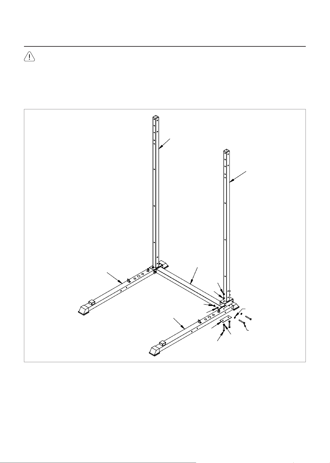
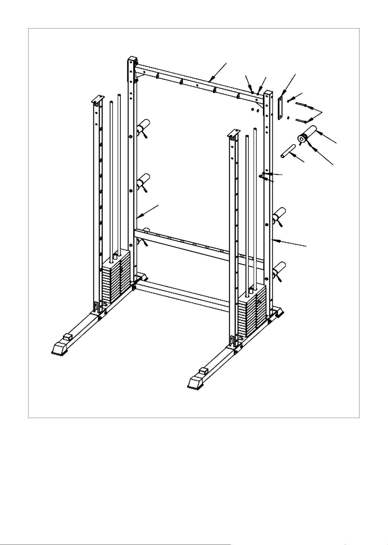
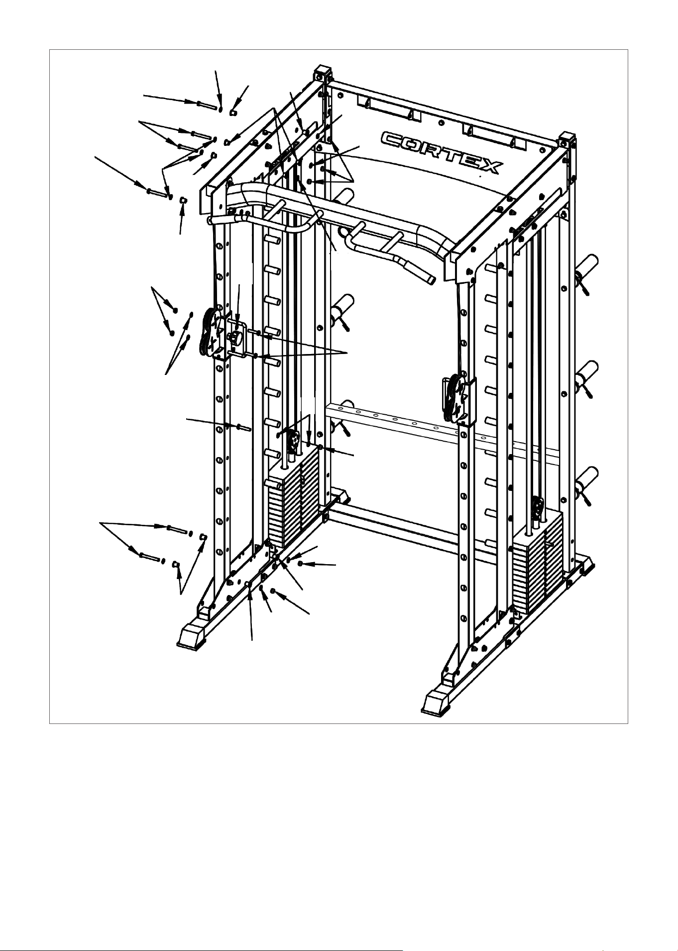
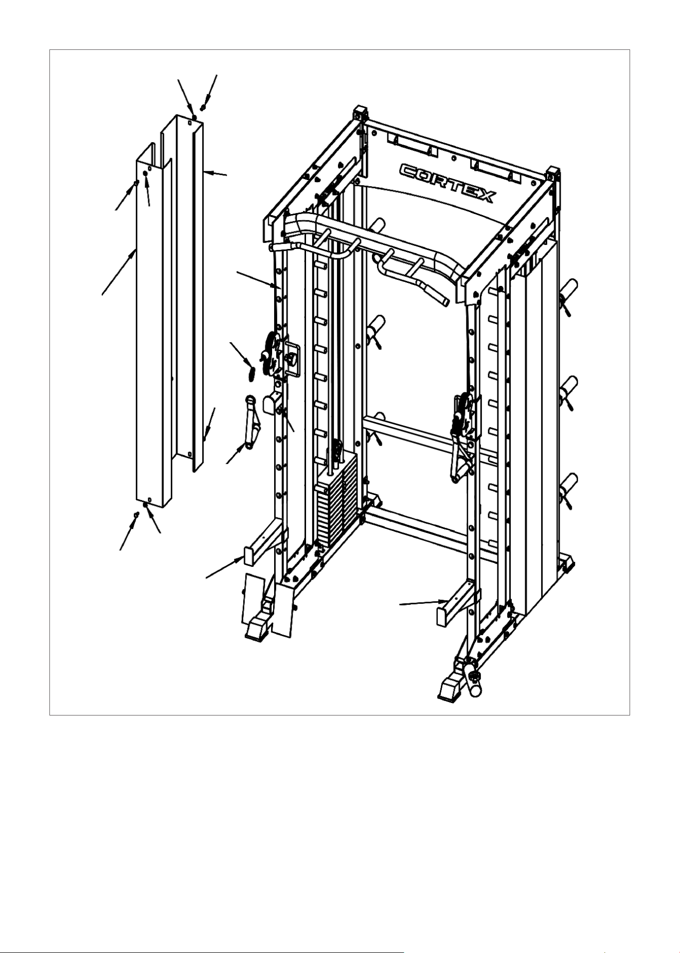
STEP 1
1. As shown, pre-install the screen connector (48#), bolts (66#) and pads (74# and 75#) under (4#).
2. Place (4#) on both sides of (5#). Place (1#) opposite holes on (4#).
3. Secure with bolts (63#), gaskets (74#), and nuts (71#).
4. Repeat for the other side.
1
1
4
5
71
74
71
74
4
48
66
75
63
74
10 | ASSEMBLY INSTRUCTIONS
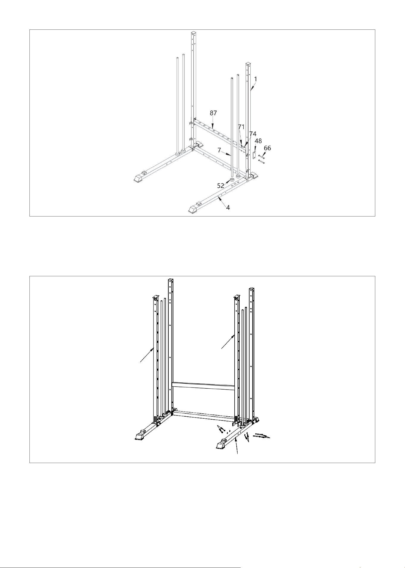
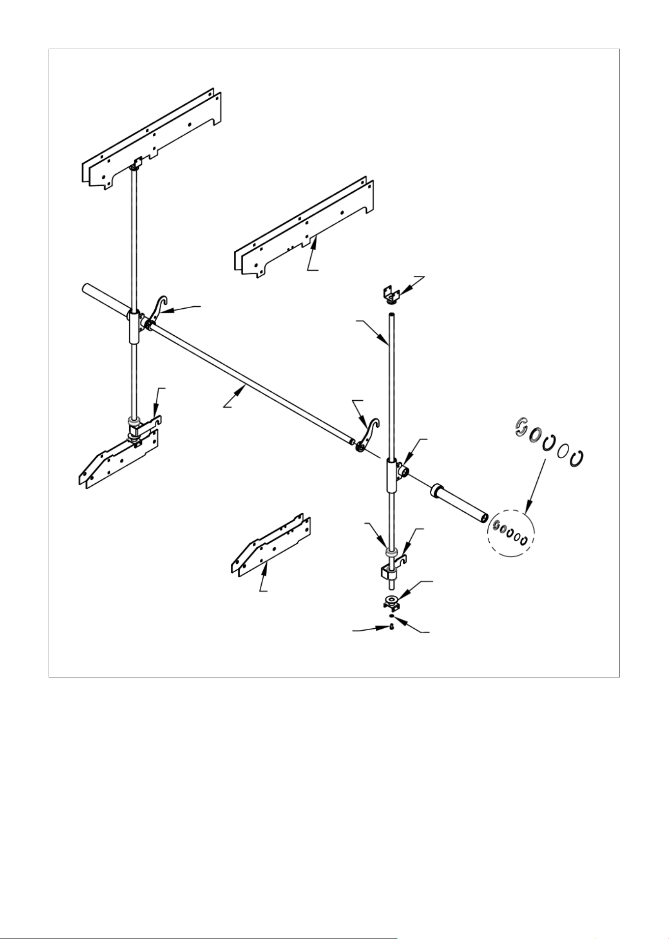
STEP 2
1. Place counter-pad (52 #) hole on (4#) as shown and insert (7#).
2. Place (87#) on both sides of (1#),tighten it with (66#) (74#) and (71#).
3. Repeat for the other side.
STEP 3
1. Place the (2#) column on (4#) as shown and secure with bolts (64#), gaskets (74#) and nuts (71#).
2. Repeat for the other side.
2
2
71
4
74
64
11ASSEMBLY INSTRUCTIONS |
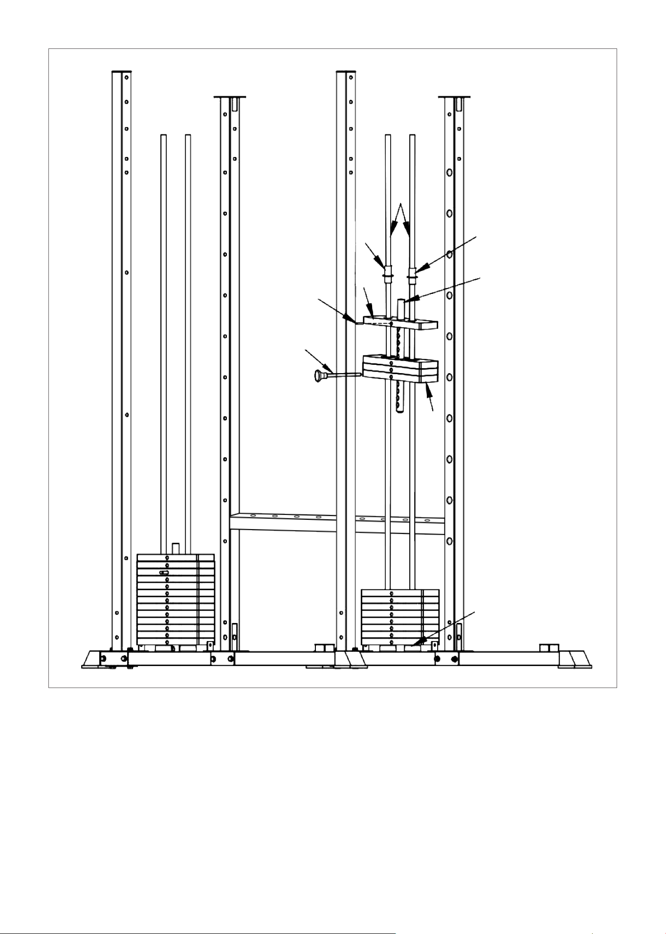
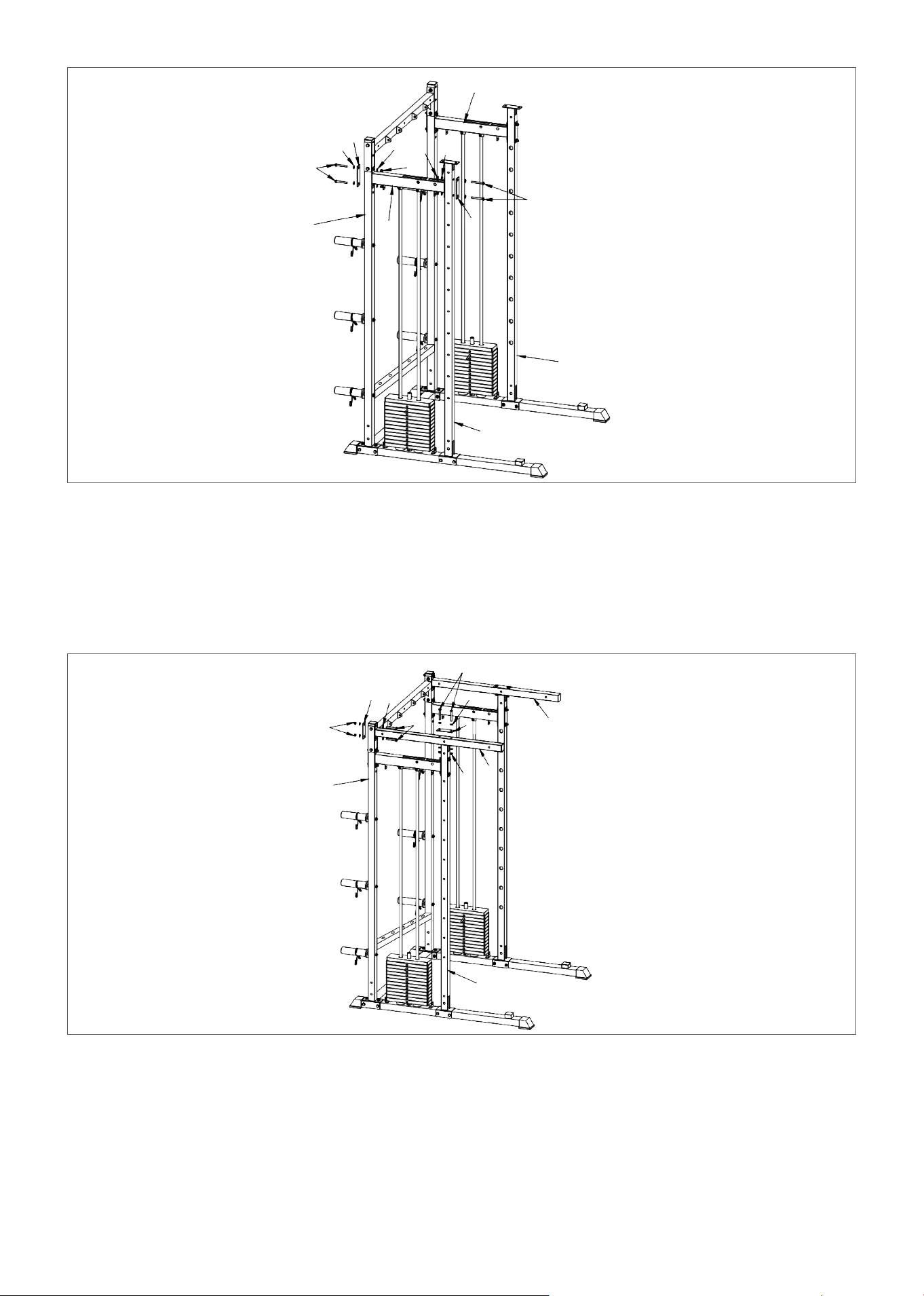
STEP 4
1. Place the counterweight block (35#) into (7#) according to the drawing, then insert the (34#)
counterweight head and (15#) counterweight bar. Fix with L-shaped counterweight pin (55#).
2. Insert (79#), (80#) according to the figure.
3. Repeat for the other side.
4. Add the sticker to the weight plates from 11kg on the top plate and finishing at 74kg (If you purchased
additional weight stacks then finish off at 96kg at the bottom).
NOTE: the 11kg top plate includes the weight of the rod in the middle.
7
80 80
79
34
15
55
35
52
12 | ASSEMBLY INSTRUCTIONS
STEP 5
1. Place the rear upper beam (8#) and flat connection plate (50#) on both sides of (1#) as shown. Fix
with bolt (66#) pads, plate (74#) and nut (71#).
2. Insert sleeve (33#) into (1#) and secure with bolt (68#) spacer (74#). Insert sleeve (44#) into (33#) and
card (53#) into (44#).
3. Repeat for the other side.
8
71
74
50
74
66
44
53
33
1
74
68
1
13ASSEMBLY INSTRUCTIONS |
STEP 6
1. Place counterweight loading (10#), flat connection plate (49#) on both sides of (1 #) and (2#) as
shown. Fix with bolt (66#), gasket (74#), and nut (71#).
2. Repeat on the other side.
NOTE: Align (7 #) to hole (10 #) and tighten the (10 #) pre-loaded nut.
STEP 7
1. Align the holes on (9#) and place the panels (48#) on the side of (1#) and (9#). Then fix with bolts
(66#), gaskets (74#) and nuts (71#).
2. Repeat for the other side.
10
49
74
66
1
71
71
74
74
10
49
66
2
2
66
74
48
71
1
71
9
66
48
9
74
2

14 | ASSEMBLY INSTRUCTIONS
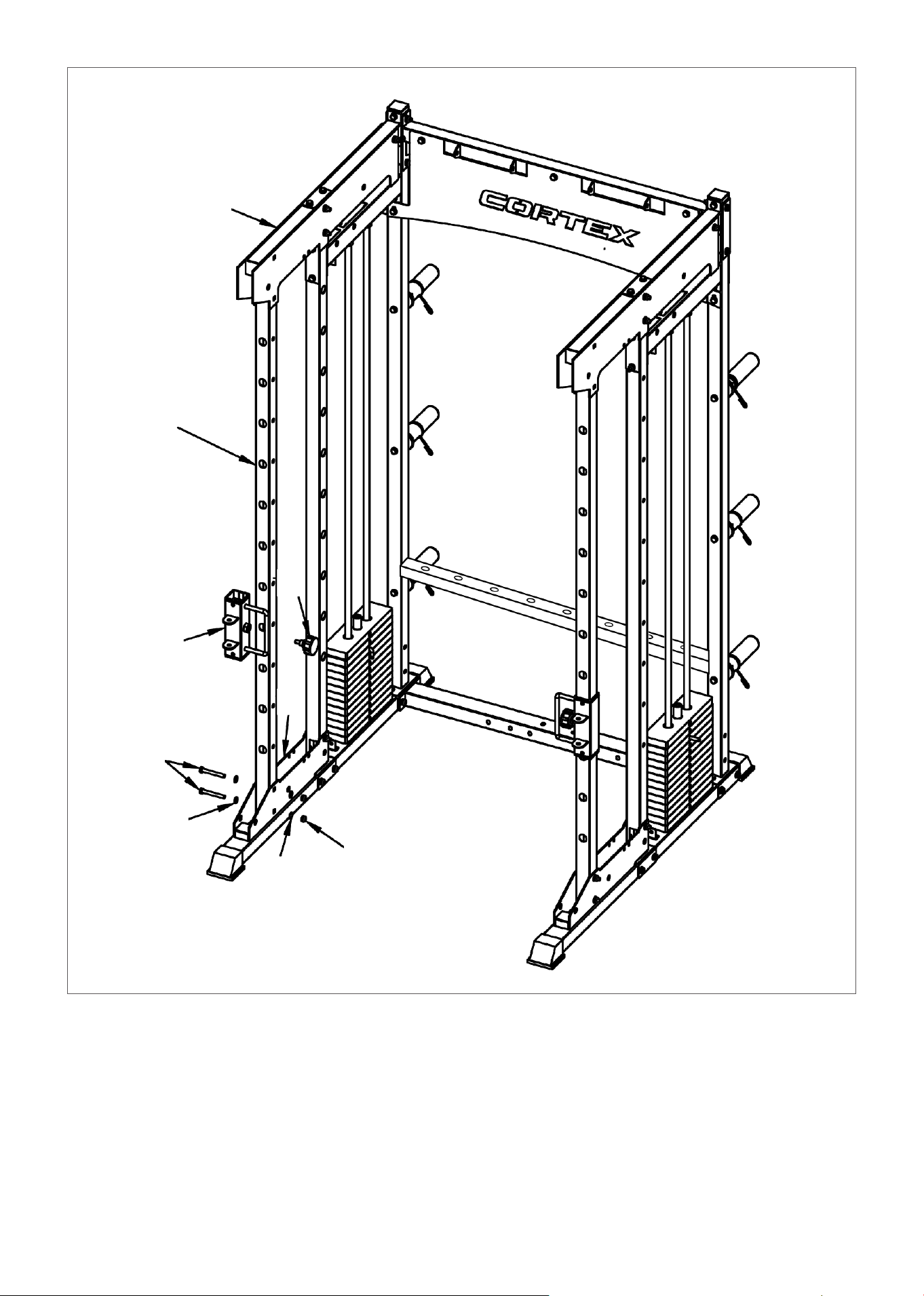
STEP 8
1. Place the rear trim plate (77#) on the side of (1#) and (8#) and secure with the bolt (66#), gasket (74#),
and nut (71#).
2. Place the upper trim plate (31#) and the lower holes on (9#) and (2#). Secure the bolt (65#), gasket
(74#) and nut (71#).
3. Repeat for the other side.
71
74
8
1
74
71
65
66
77
31
9
2
1
74
65
32
74
71
15ASSEMBLY INSTRUCTIONS |
STEP 9
1. Set the cable adjuster sleeve (19#) with lock pin (76#).
2. Align the holes on (3#) to the parts (31#) and (32#) and secure with bolts (65#), gasket (74#) and nut
(71#).
3. Repeat for the other side.
31
3
19
76
32
65
74
74
71
16 | ASSEMBLY INSTRUCTIONS
STEP 10
1. According for the figure, install the lead handles (16#) and (17#) on the front upper beam (11#) and
secure with bolts (68#) and spacer (74#).
2. Place the installed (11#) holes on both sides of (31#) and secure with bolt (65#), gasket (74#), and nuts
(71#).
31
74
74
65
17
16
11
68
65
17ASSEMBLY INSTRUCTIONS |
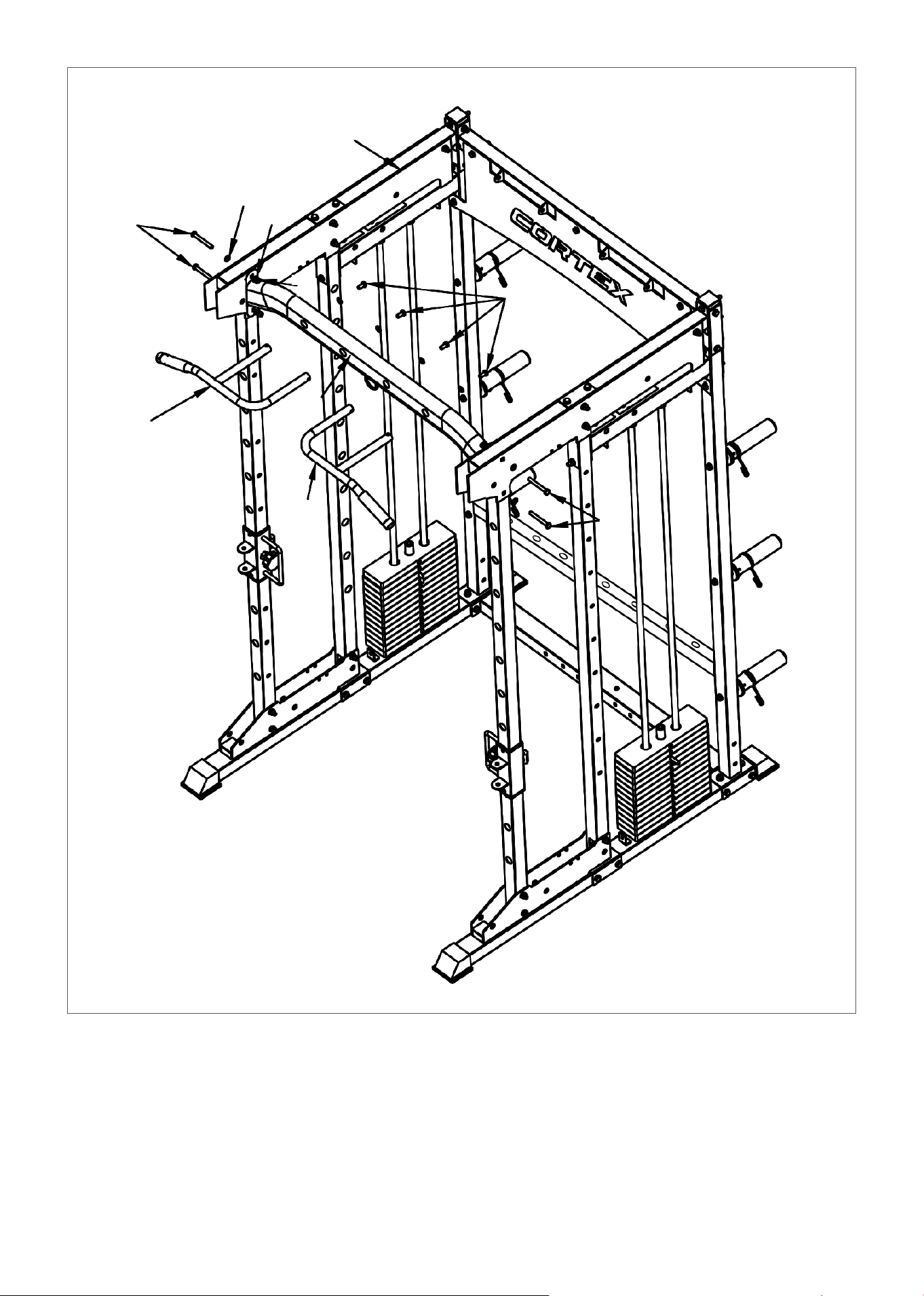
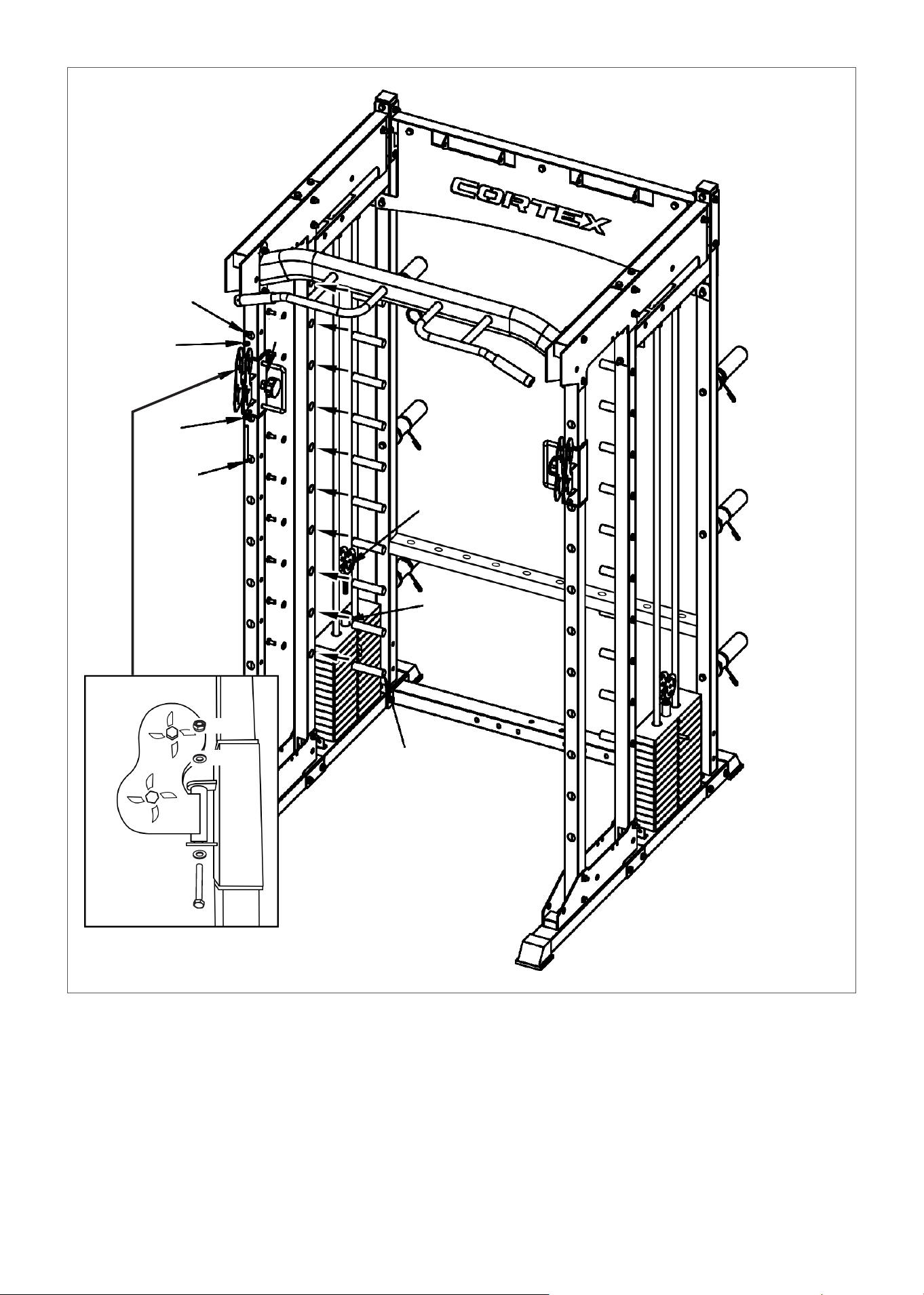
STEP 11
1. Twist the small pulley frame (39#) into (15#) as shown, then place the short optical shaft (44#)
into (2#) with pre-installed bolts.
2. Place the pulley bracket (26#) into the hole of (19#) and secure with bolt (62#), gasket (74#),
and nut (71#).
3. Repeat for the other side.
71
74
26
74
62
39
15
44
26
19
64
74
71
74
18 | ASSEMBLY INSTRUCTIONS
2
1
6
3
4
5
7
8
9
10
67 74 74 71
60
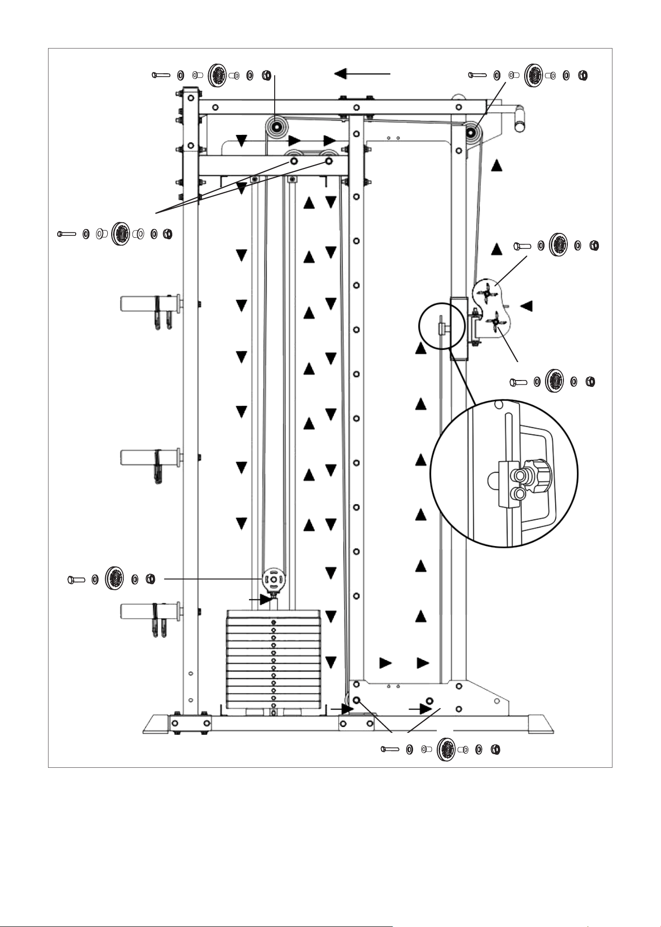
Direction for the Cables & Parts Required
NOTE: Washers must go on both sides. After the bolt and before the nut.
Parts #56 and #57 (if applicable) goes on both sides of the pulley.
See next diagram for direction for bolt installation.
65 74 74 7156 56
60
65 74 74 7156 56
60
67 74 74 71
61
67 74 74 71
61
66 74 57 57 74 71
60
65 74 74 7156 56
60
19ASSEMBLY INSTRUCTIONS |
STEP 12
1. Refer to the previous page and step 12 diagrams for the order of fittings and use the arrows as
direction for start to end point. Start from the ball end of the cable.
2. Feed the cables into the pulley first before then secure pulley to pulley frame.
3. When you reach to the end of the cable (refer to zoom image in previous page), adjust the cable
length so that it is not too loose and tighten with the pre-installed bolts.
4. Check that your cables are running smoothly and tighten all bolts.
65
65
66
74
74
56
56
57
57
56
71
74
67
65
56
56
74
74
71
74
67
71
74
71
56
71
74
74
74
20| ASSEMBLY INSTRUCTIONS
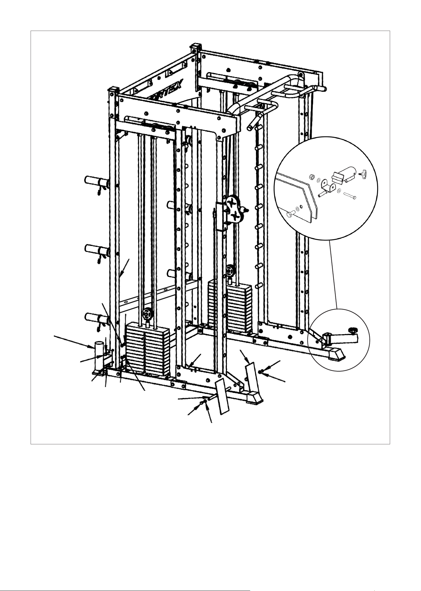
STEP 13
1. Place the Foot plate (18#) on both sides of (32#) according to the picture. Fit the (38#) into the foot
plate shaft and secure with (68#) spacer and (68#).
2. First place the M10 knob (54#) on the landmine post (27#). Install (27#) on the barrel shaft (45#) and
then place (45#) hole into (32#) with bolt using nut (71#), bolt (64#) and washer (74#).
3. Place the hole in the Olympic rod holder (20#) on the side of (1#) and secure with the bolt (66#),
gasket (74#) and nut (71#).
74
71
1
74
20
66
66
74
74
71
38
68
74
32
18
68
68
74
71
74
74
64
54
27
45
74
68
21ASSEMBLY INSTRUCTIONS |
STEP 14
1. First install (36#) and (37#) onto the holes on (4#) and (10#) using bolts (68#), insert (74#) and then
fix the 2 plates with bolts (70#) and nut (73#).
2. Attach the handle (51#) on C type buckle (59#) and then attach (59#) to the pulley rope.
3. Insert (13#) and (14#) into the front columns as pictured. They can be removed when using other
accessories like dip handles.
4. Repeat for the other side.
74
68
37
68
74
36
68
74
14
51
68
59
3
14
13
22| ASSEMBLY INSTRUCTIONS
STEP 15
1. According to the diagram, feed the light shaft bottom set (46#), safety hook (24#), damping pad
2. (52#), bearing sleeve (25#) onto smith guide rod (6#). Secure the light shaft bottom set (46#) to the
rod with bolt (68#) and gasket (74#), then set the light shaft upper set (47#). Light shaft bottom and
upper set will later get bolted to the side covers (31# & 32#).
3. Pass the rod (12#) into buckle hook (41# & 42#), then on each side place the rod into bearing holder
(25#). Make sure your hooks 41# and 41# are facing in the direction of the pegs (44#).
4. Finally, add the barbell sleeve to the rods and secure using the installation sequence at the ends of
the sleeve.
Installation sequence
inside the sleeve
41
31
6
25
42
24
12
23
52
46
32
74
68
47
23ASSEMBLY INSTRUCTIONS |
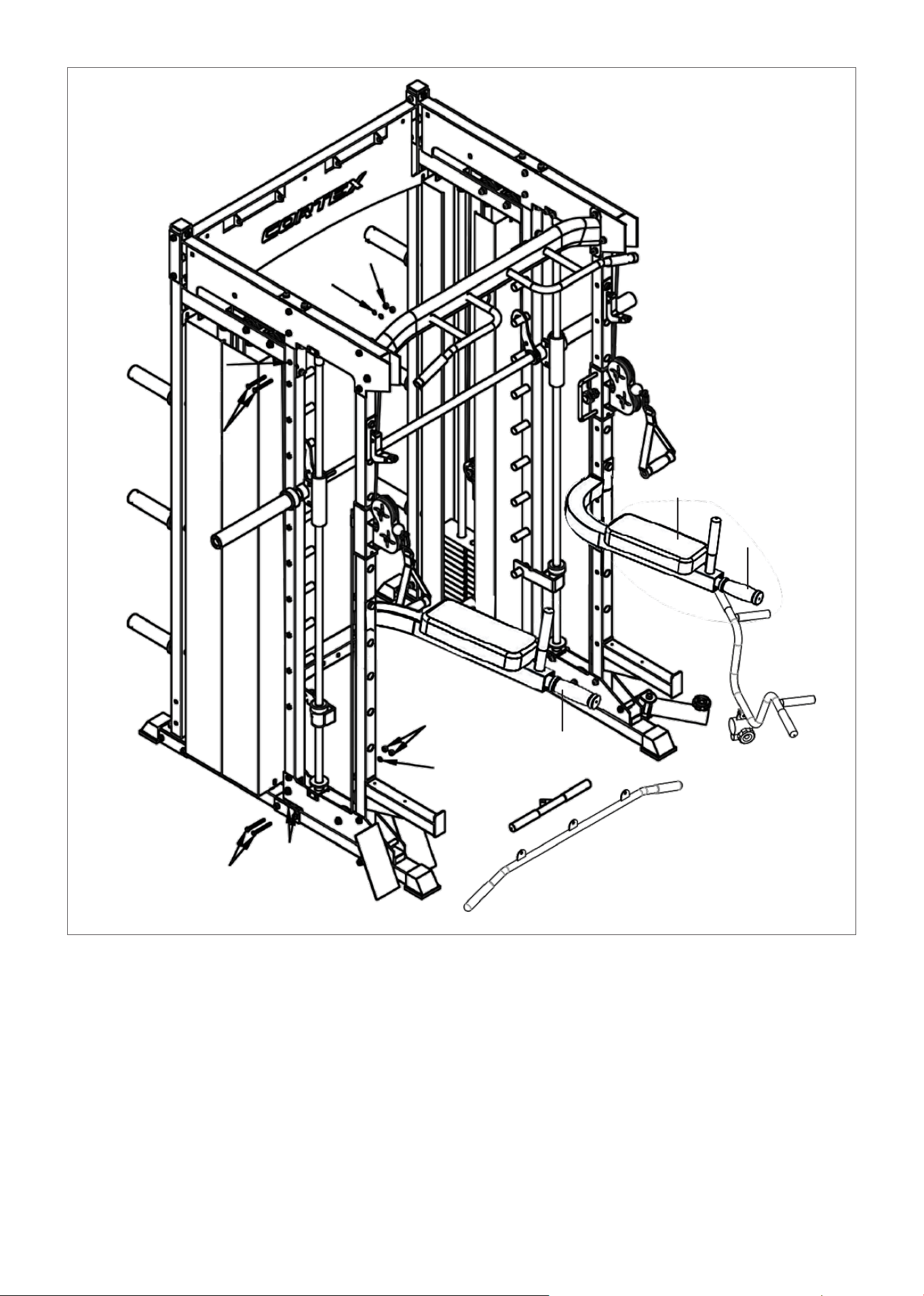
STEP 16
1. Secure the installed Olympic rod onto the side covers (31#) and (32#) as shown, using bolt (69#),
gasket (75#), and nut (72#).
2. Attach the padding (90#) to the left and right dip handles (21 and 22) using M8*65mm bolts. Then
hook it to the front column when in use.
Please ensure to tighten all bolt and nuts with a wrench.
Check that all pulleys and wire ropes are secured properly. If cables are not sliding smoothly then the
bolts on the pulley may be over tighten, loosen it slightly. You can also lubricate the pulley.
75
72
75
69
69
75
75
72
90
21
22
24
V. EXERCISE GUIDE
PLEASE NOTE:
Before beginning any exercise program, consult your physician. This is important especially if you are over the
age of 45 or individuals with pre-existing health problems.
The pulse sensors are not medical devices. Various factors, including the user’s movement, may affect the
accuracy of heart rate readings. The pulse sensors are intended only as an exercise aid in determining heart
rate trends in general.
Exercising is great way to control your weight, improving your fitness and reduce the effect of aging and stress.
The key to success is to make exercise a regular and enjoyable part of your everyday life.
The condition of your heart and lungs and how efficient they are in delivering oxygen via your blood to your
muscles is an important factor to your fitness. Your muscles use this oxygen to provide enough energy for daily
activity. This is called aerobic activity. When you are fit, your heart will not have to work so hard. It will pump a lot
fewer times per minute, reducing the wear and tear of your heart.
So as you can see, the fitter you are, the healthier and greater you will feel.
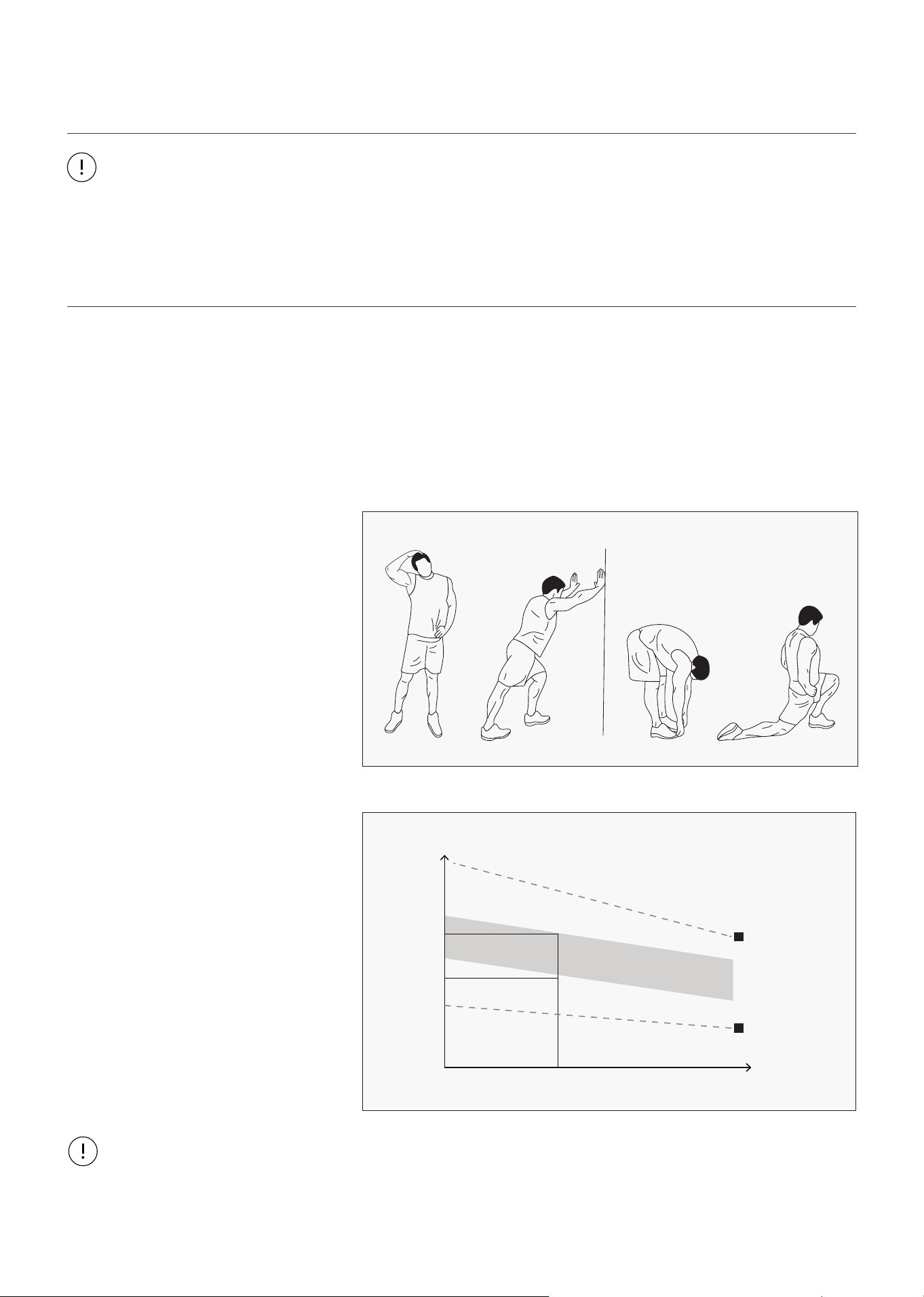
WARM UP
Start each workout with 5 to 10
minutes of stretching and some light
exercises. A proper warm-up increases
your body temperature, heart rate and
circulation in preparation for exercise.
Ease into your exercise.
After warming up, increase the
intensity to your desired exercise
program. Be sure to maintain your
intensity for maximum performance.
Breathe regularly and deeply as you
exercise.
TARGET ZONE
MAXIMUM
85%
70%
COOL DOWN
AGE
HEART RATE
200
180
160
140
120
100
80
20 25 30 35 40 45 50 55 60 65 70 75
WORKOUT GUIDELINES
COOL DOWN
Finish each workout with a light jog
or walk for at least 1 minute. Then
complete 5 to 10 minutes of stretching
to cool down. This will increase the
flexibility of your muscles and will help
prevent post-exercise problems.
This is how your pulse should behave during general fitness exercise. Remember to warm up and cool down
for a few minutes.
| EXERCISE GUIDE

25
VI. MAINTENANCE
MAINTENANCE METHOD:
To extend the service life of the device, the parts must be lubricated on time. The product has been
initially lubricated before leaving the factory, but lubrication is required between the guide rod and
the weight plate over time.
1. Pulley and wire ropes should be regularly checked for signs of wear.
2. Check and adjust the tension of the wire rope regularly.
3. Check all moving parts regularly. If there is a damaged part, stop using the device immediately and
contact the store.
4. Ensure all bolts and nuts are fully fixed and re-tighten them when it is loose.
5. Check the welding for cracks.
6. Failure to perform routine maintenance may cause personal injury or equipment damage.
7. Ensure any handle attachments are fully secured before use to prevent from injury.
NOTE: Silicon oil/spray is recommended for lubrication.
MAINTENANCE |

26
VII. WARRANTY
AUSTRALIAN CONSUMER LAW
Many of our products come with a guarantee or warranty from the manufacturer. In addition, they come
with guarantees that cannot be excluded under the Australian Consumer Law. You are entitled to a
replacement or refund for a major failure and compensation for any other reasonably foreseeable loss
or damage.
You are entitled to have the goods repaired or replaced if the goods fail to be of acceptable quality and
the failure does not amount to a major failure. Full details of your consumer rights may be found at
www.consumerlaw.gov.au.
Please visit our website to view our full warranty terms and conditions:
http://www.lifespanfitness.com.au/warranty-repairs
WARRANTY AND SUPPORT
Any claim against this warranty must be made through your original place of purchase.
Proof of purchase is required before a warranty claim may be processed.
If you have purchased this product from the Official Lifespan Fitness website, please visit
https://lifespanfitness.com.au/warranty-form
For support outside of warranty, if you wish to purchase replacement parts or request a repair or
service, please visit https://lifespanfitness.com.au/warranty-form and fill in our Repair/Service
Request Form or Parts Purchase Form.
Scan this QR code with your device to go to lifespanfitness.com.au/warranty-form
| WARRANTY


WWW.LIFESPANFITNESS.COM.AU