
Technical Support and E-Warranty Certificate
www.vevor.com/support
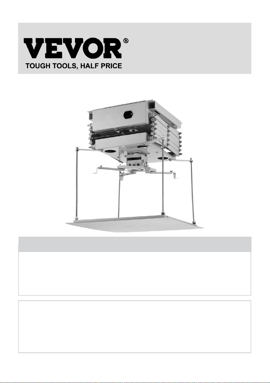
MOTORIZED PROJECTOR LIFT
USER MANUAL
MODEL:TLMPL-1M, TLMPL-1.5M
We continue to be committed to provide you tools with competitive price.
"Save Half", "Half Price" or any other similar expressions used by us only represents an
estimate of savings you might benefit from buying certain tools with us compared to the major
top brands and does not necessarily mean to cover all categories of tools offered by us. You
are kindly reminded to verify carefully when you are placing an order with us if you are
actually saving half in comparison with the top major brands.

1
MODEL: TLMPL-1M, TLMPL-1.5M
Have product questions? Need technical support? Please feel free to
contact us:
Technical Support and E-Warranty Certificate
www.vevor.com/support
NEED HELP? CONTACT US!
This is the original instruction, please read all manual instructions
carefully before operating. VEVOR reserves a clear interpretation of our
user manual. The appearance of the product shall be subject to the
product you received. Please forgive us that we won't inform you again if
there are any technology or software updates on our product.
MOTORIZED PROJECTOR LIFT

2
SAFETY INSTRUCTIONS
WARNING:
Read this material before using this product. Failure to do so can
result in serious injury.
Assembly precautions
1. Assemble only according to these instructions. Improper assembly can
create hazards.
2. Wear safety goggles and duty work gloves during assembly.
3. Keep the assembly area clean and well-lit.
4. Keep bystanders out of the area during assembly.
5. Do not assemble when tired or when under the influence of alcohol,
drugs or medication.
6. The product capabilities apply to properly and completely assembled
products only.
7. Assemble on a flat, level, hard and smooth surface capable of safely
supporting the Motorized Projector Lift.
8. For additional information regarding the parts listed in the following
pages, please refer to the Assembly Diagram of this manual. Unwrap
and separate all parts in a clean work area.
Use precautions
1. DO NOT SIT OR STAND ON THIS ITEM.
2. This product is not a toy. Do not allow children to play with or near this
item.
3. Do not exceed Weight Capacities.
4. Use only on a flat, level, hard and smooth surface capable of safely
supporting a fully loaded Motorized Projector Lift.
5. Use as intended only.
6. Inspect before every use; do not use if parts are loose or damaged.
SAVE THIS MANUAL
3
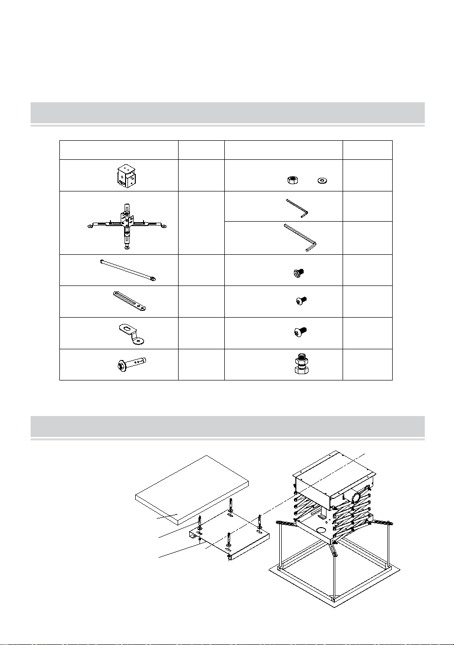
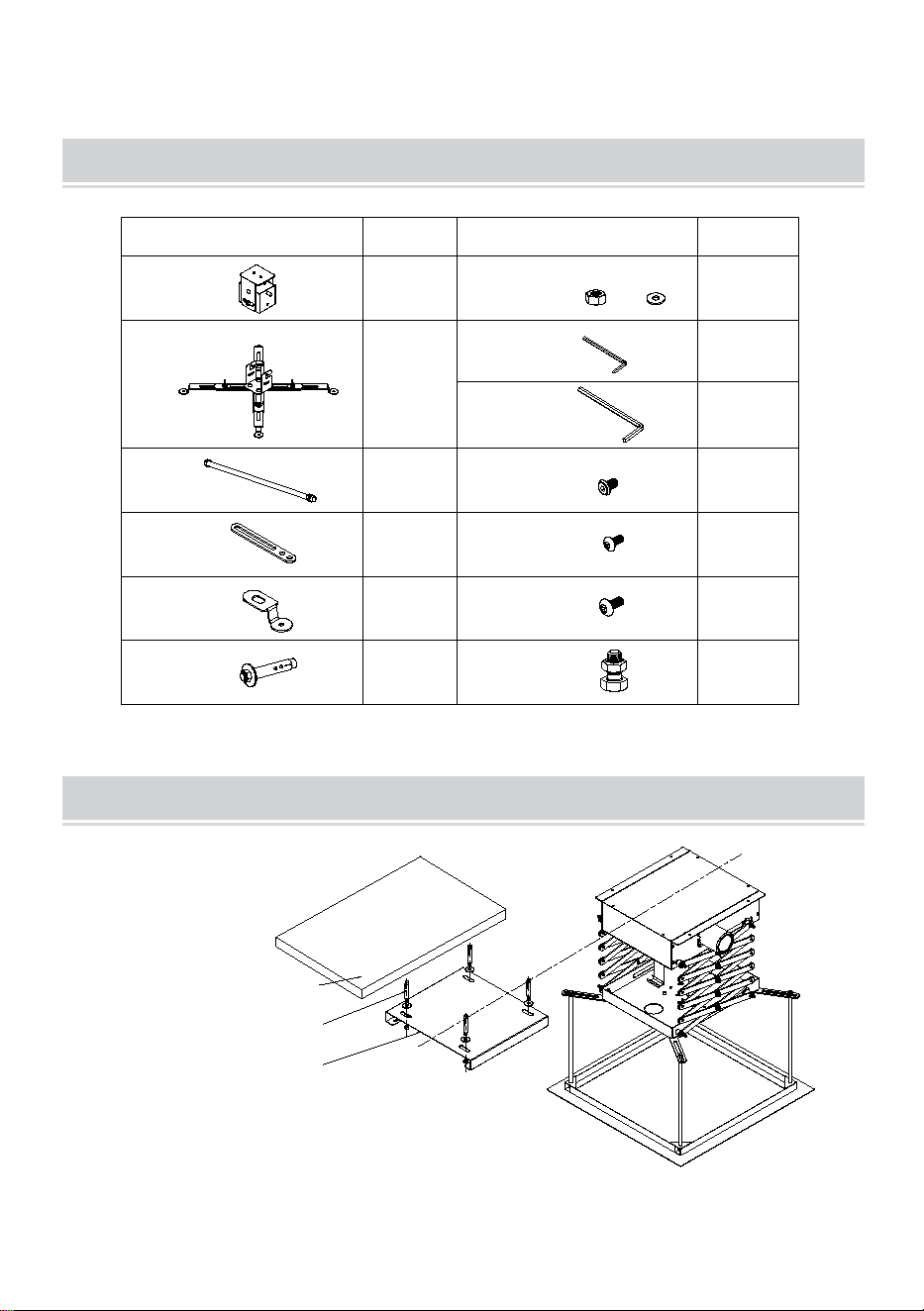
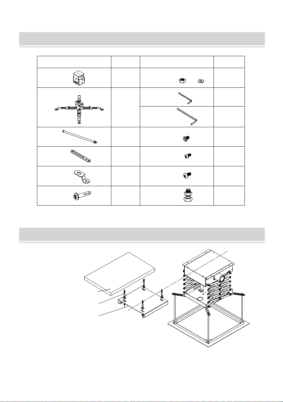
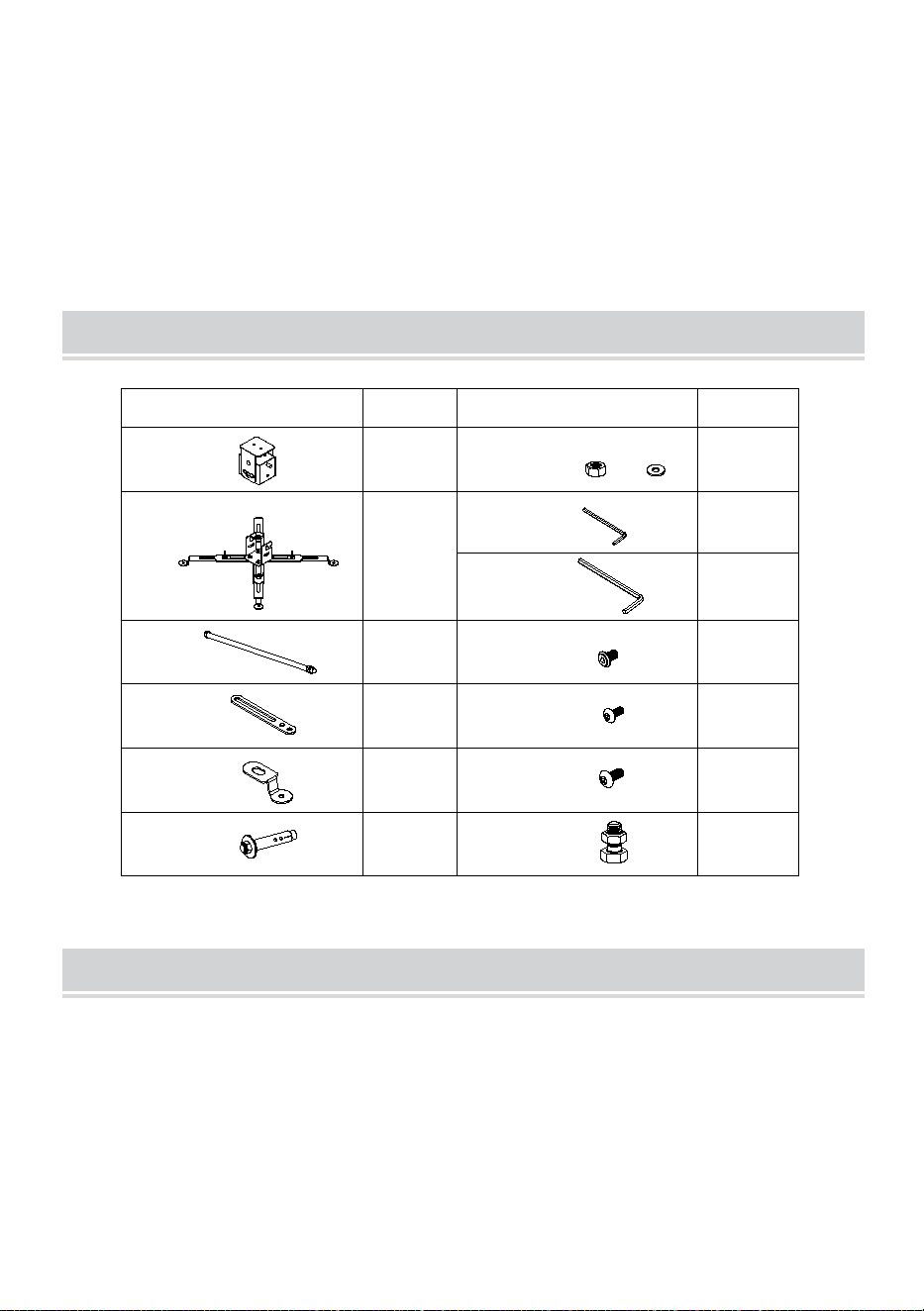
PACKAGE LIST
A:
B:
C:
D:
E:
F:M8*70
G:M4
H:M3
I:M4
J:M4*10
1 pcs
1 pcs
4 pcs
4 pcs
2 pcs
4 pcs
1 pcs
1 pcs
10 pcs
6 pcs
K:M3*12
4 pcs
L:M4*12
6 pcs
M:M8*16
4 pcs
Image
Quantity
Image
Quantity
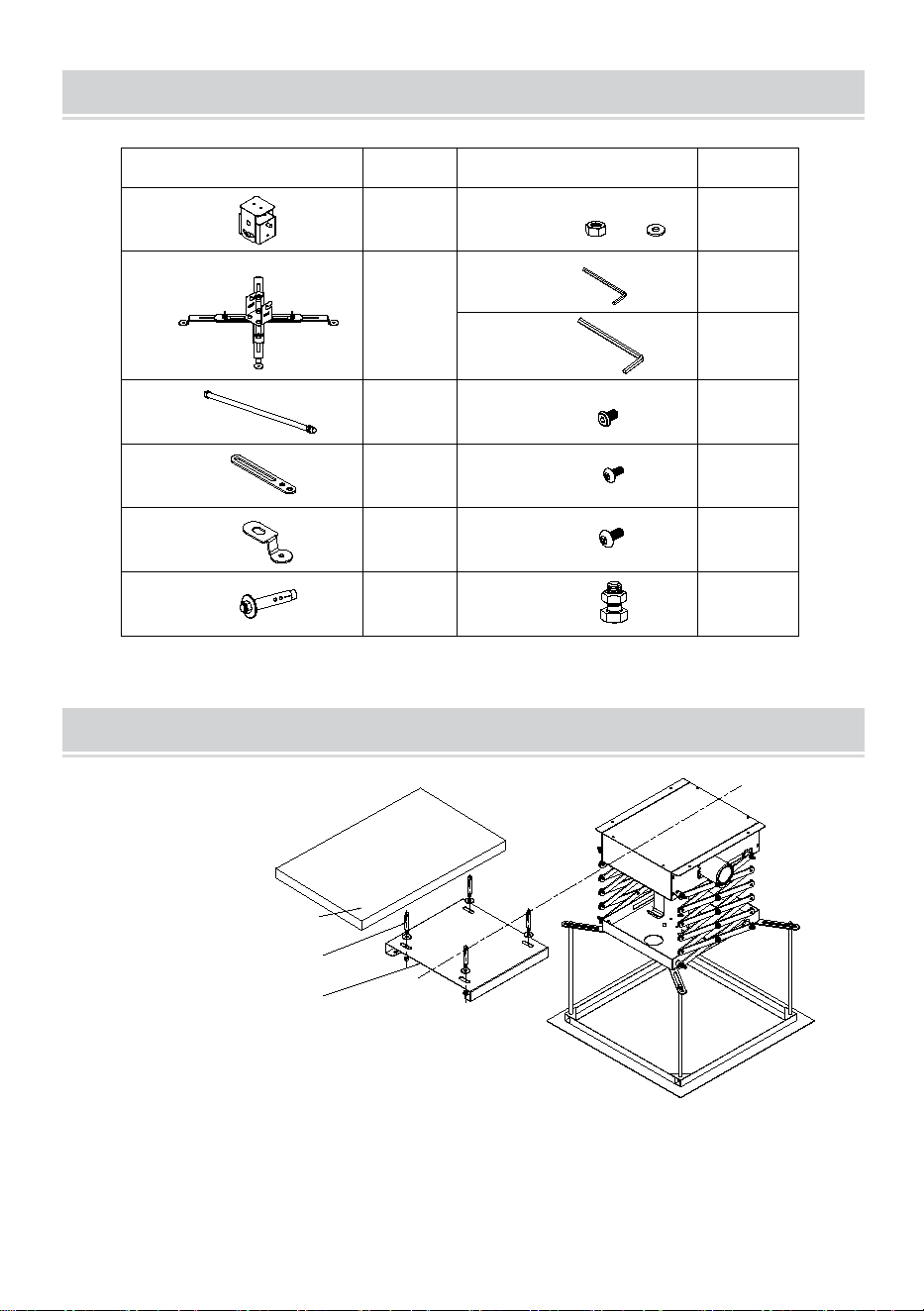
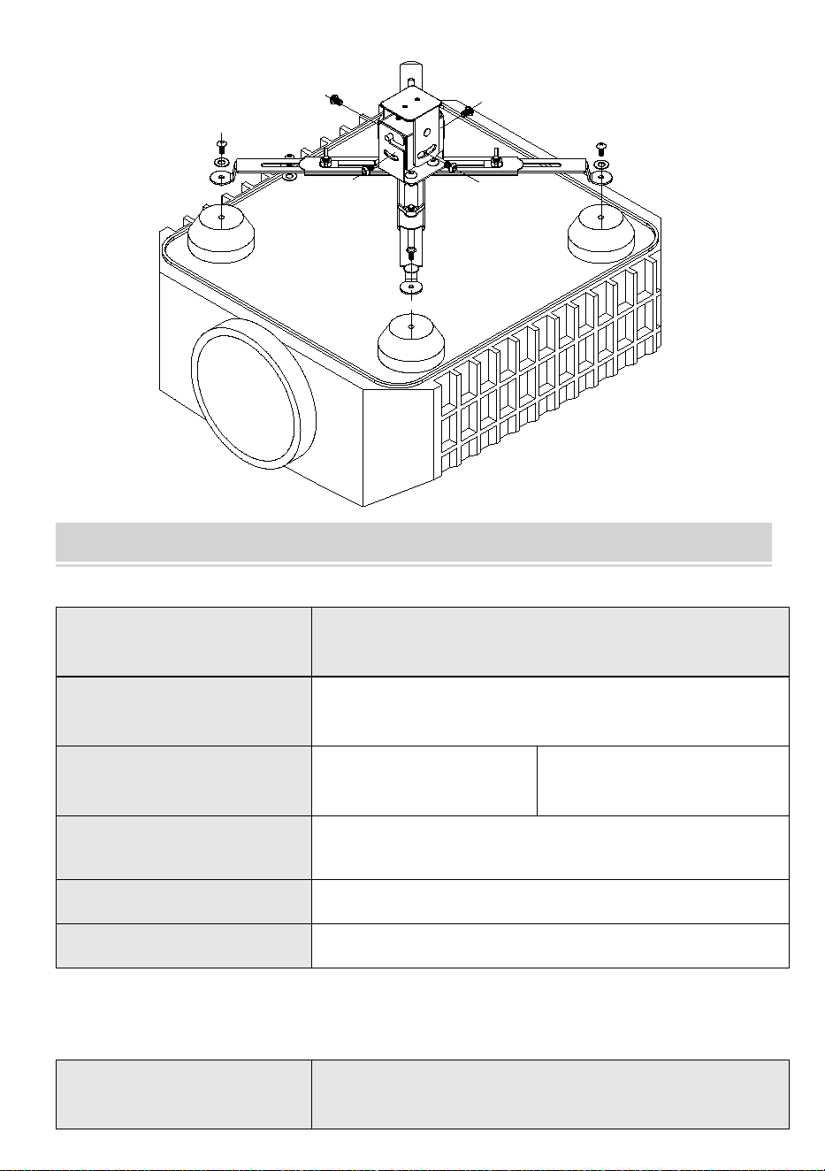
Parts list:
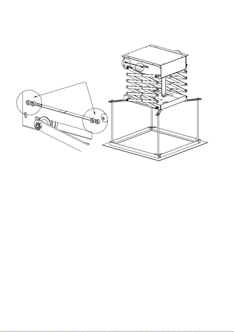
ASSEMBLY STEP
Cement ceiling
Bolts
mounting plate,
fixed to the celing
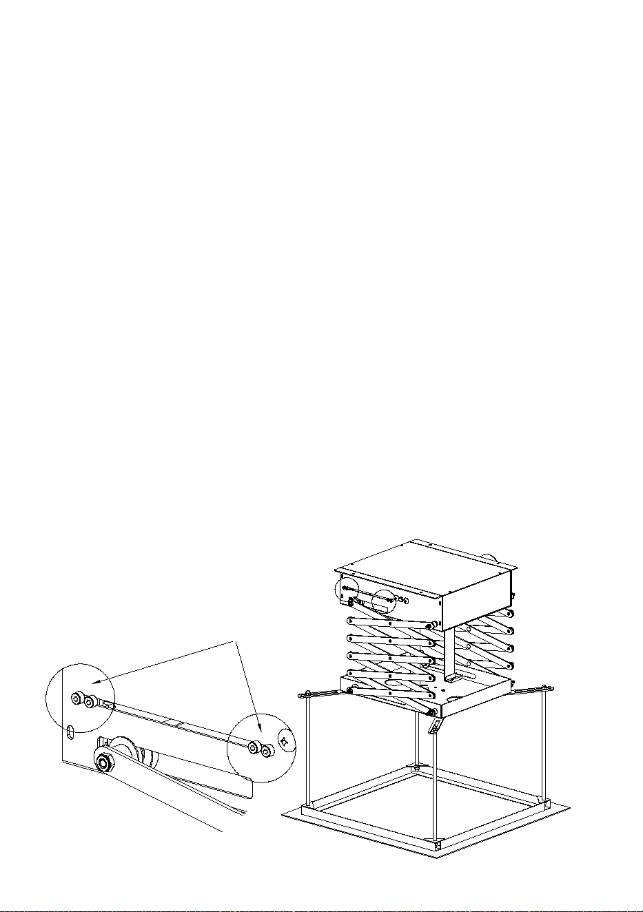
We recommend that you install electric pylons in the following order:

4
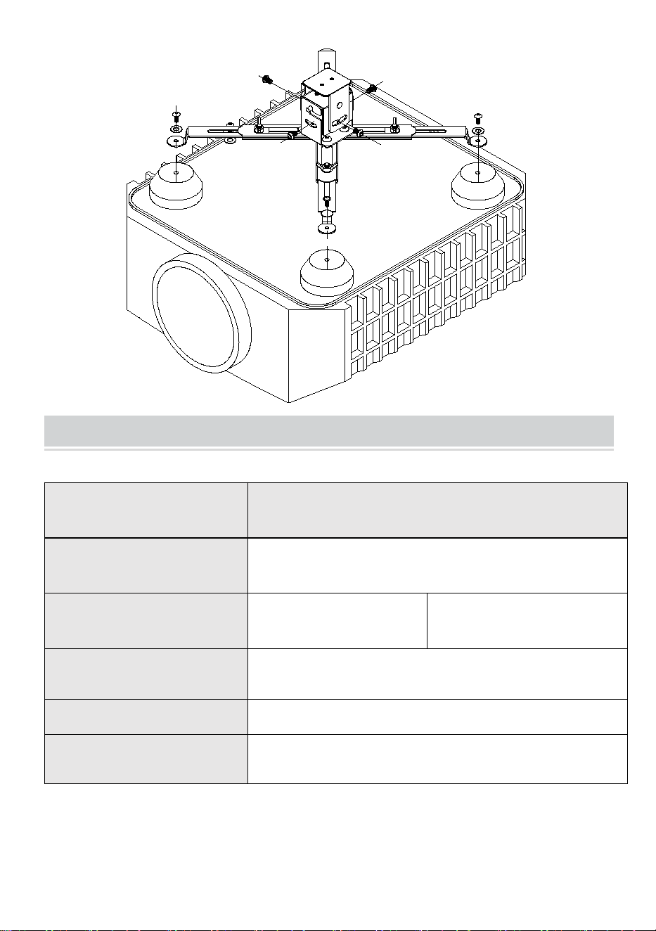
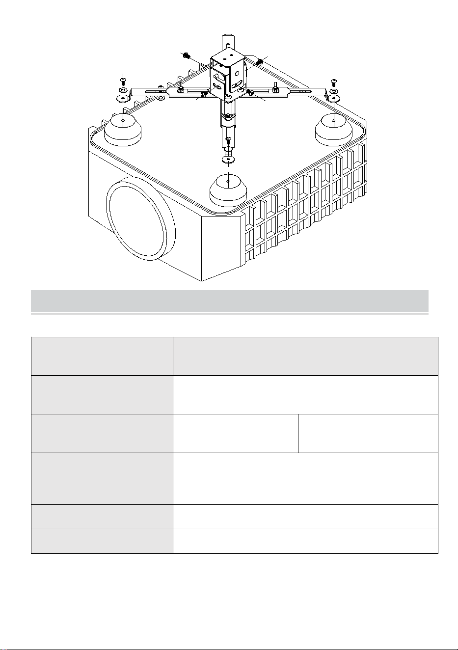
By the focal length of the screen size and the projector is based on
determining the distance between the hanger and the screen, set a good
hanger installation location. The installation hole in the ceiling hanger plate
according to size. Meanwhile recommended installation position reserved
for the maintenance side of the hole(40*40cm)
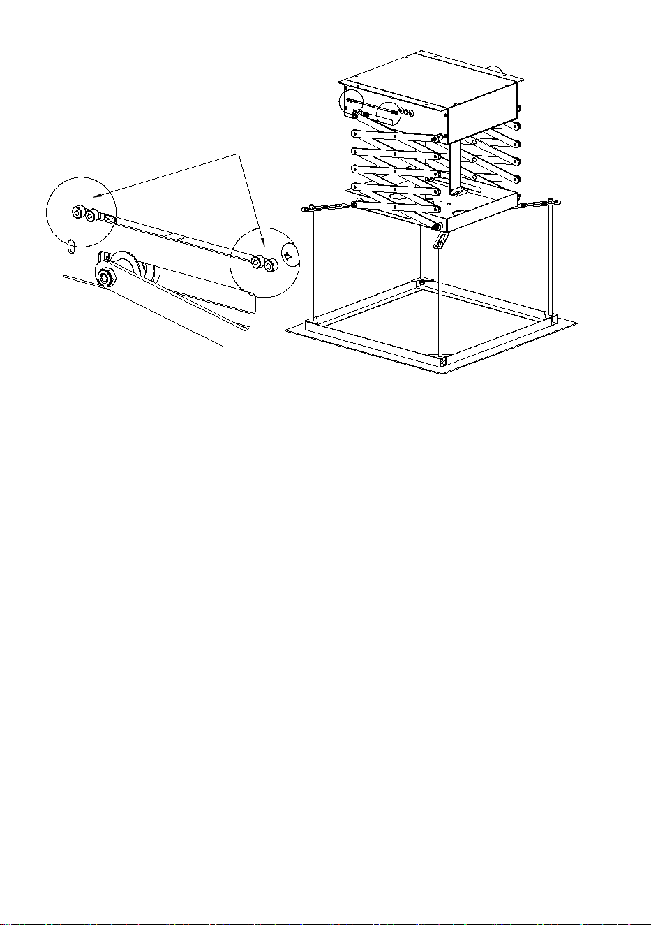
After a good mounting holes on the ceiling, measuring four runways
mounting plate holes center distance (211 * 225mm), in order to prevail on
the ceiling with the impact of drilling, the distribution of the four M10 * 80
bolts embedded on the ceiling。
3、The mounting plate is inserted bolts, and tighten the nut on the
mounting plate is fixed to the ceiling。
4、 The hanger into the mounting plate. With four M5 * 12mm screwed
between the hanger and mounting plate.
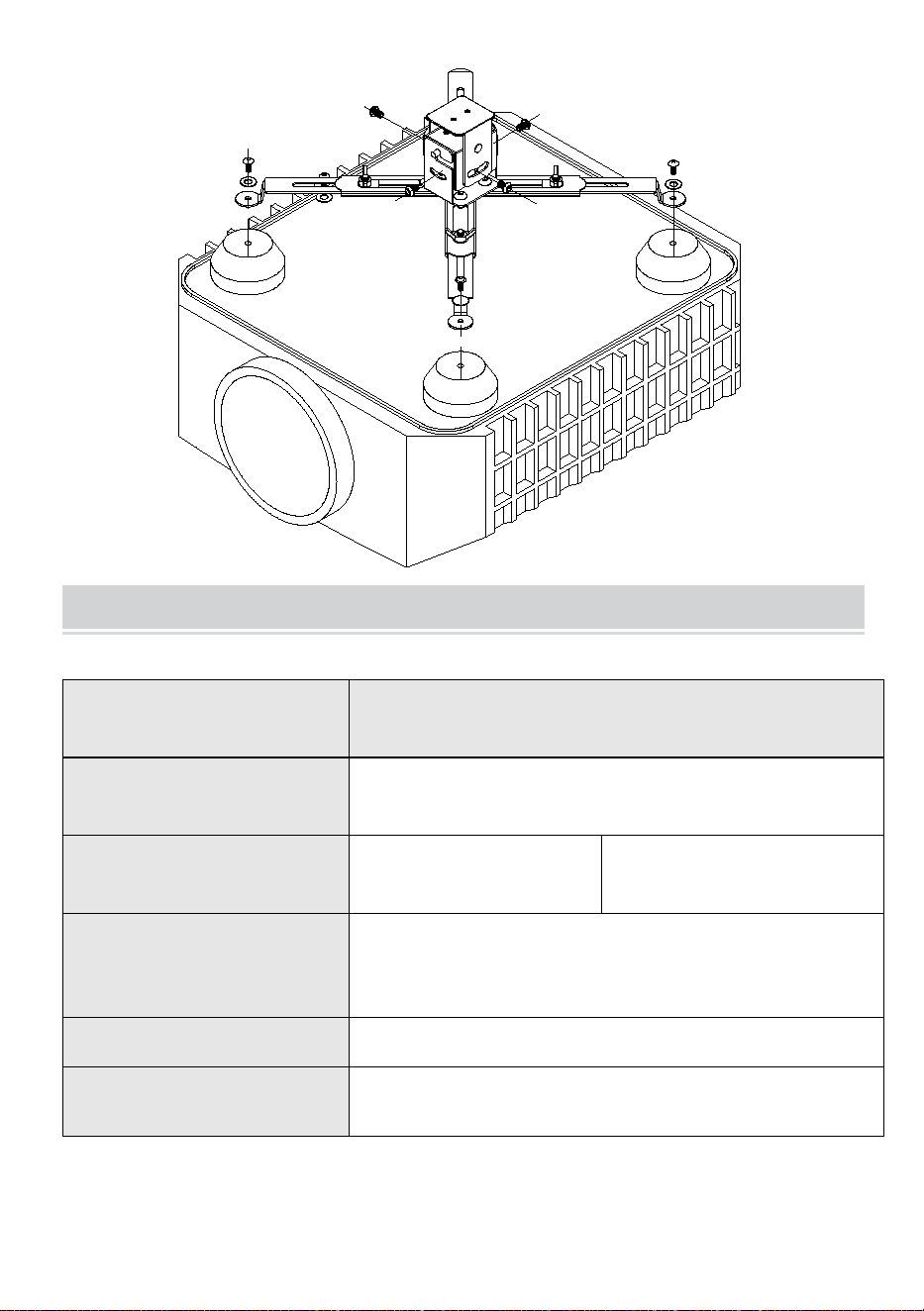
5、 Plug the remote control is powered by running down. Hanger
factory set up, the next trip. Run to the next trip, hanger stop running.
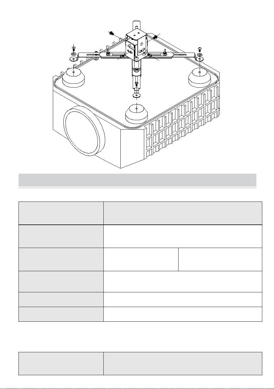
6、After installing the projector, with four M8 screw to connect the base
plate and hanger. M6 bolts scissors mounting plate installed with the
delivery of universal head。
7、According to the height of the screen, adjust the electric pylons trip.
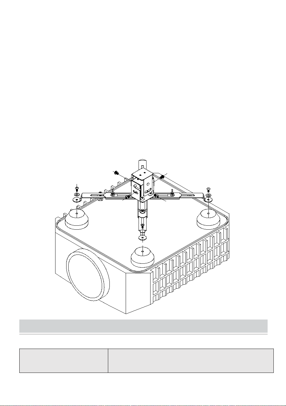
Adjustment method:

5
Loosen the screws
slightly,moving the
location of this block.
Use a screwdriver to slightly loosen the stroke positioning block diagram
(on the right) screws (not to screw off), this position is slightly shifted to the
left block, tighten the screws. Run hanger, hanger observed downstream
location. Repeat this action until you find a suitable screen hanger height.
Adjust the upper limit, release the leftmost stroke positioning block, to the
right, tighten the screws. Run hanger, hanger observed upward position.
Repeat this action until you find a suitable screen hanger height. Note:
After adjusting the upper and lower limit, we must tighten the fixing screws,
otherwise, will occur in the operation hanger positioning, localization of
running. For 2M hanger, when adjusting the upper limit, do not let the
scissors completely collapsed. (So no it stops the motor function)
7
RECOVERY AND DISPOSAL
This product complies with the provisions of the European Directive
2012/19/EC. The symbol marked with a crossed out wheelie bin indicates
that this product requires separate recycling in the EU. The same is true for
products and all accessories marked with this symbol. Products marked as
such must not be disposed of with normal household waste, but must be
taken to a collection point for the recycling of electrical and electronic
equipment.
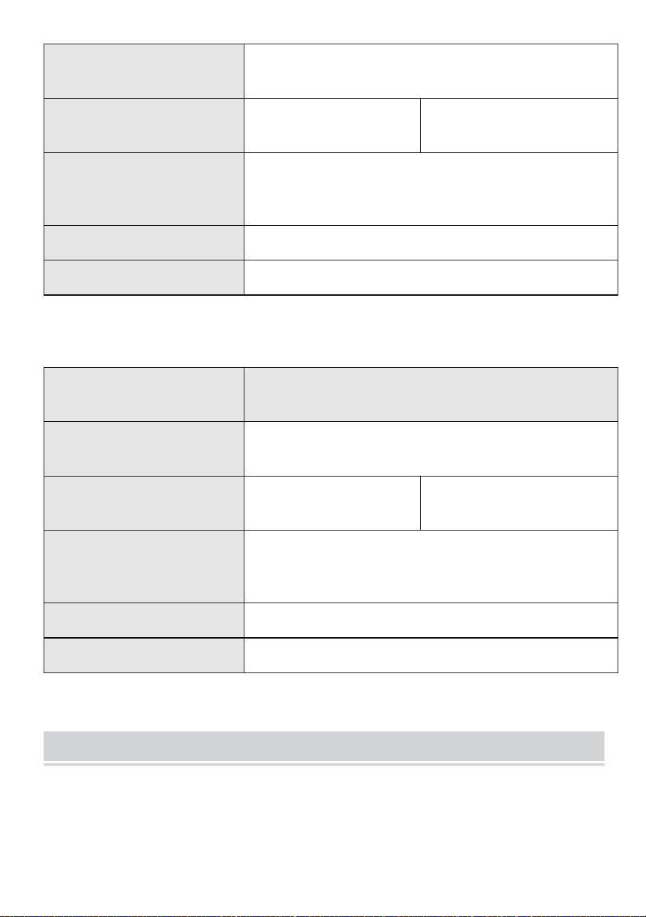
Model
TLMPL-1.5M
Power
38W
Voltage
110-120VAC 60Hz
220-240VVAC 50Hz
Maximum Loaded Weight
Max 15kg
(It is recommended to use within 10kg of load.)
Product Size
343*315*215 mm
Telescopic stroke
Max:1.5m

8
Correct Disposal
This product is subject to the provision of european Directive 2012/19/EU.
The symbol showing a wheelie bin crossed through indicates that the
product requires separate refuse collection in the European Union. This
applies to the product and all accessories marked with this symbol.
Products marked as such may not be discarded with normal domestic
waste, but must be taken to acollection point for recycling electrical and
electronic devices.
FCC Information:
CAUTION: Changes or modifications not expressly approved by the party
responsible for compliance could void the user's authority to operate the
equipment!
This device complies with Part 15 of the FCC Rules. Operation is subject to
the following two conditions:
1) This product may cause harmful interference.
2) This product must accept any interference received, including
interference that may cause undesired operation.
WARNING: Changes or modifications to this product not expressly
approved by the party.responsible for compliance could void the user's
authority to operate the product.
Note: This product has been tested and found to comply with the limits for
a Class B digital device pursuant to Part 15 of the FCC Rules, These limits
are designed to provide reasonable protection against harmful interference
in a residential installation.
This product generates, uses and can radiate radio frequency energy, and
if not installed and used in accordance with the instructions, may cause
harmful interference to radio communications. However, there is no
guarantee that interference will not occur in a particular installation. If this
product does cause harmful interference to radio or television
reception,which can be determined by turning the product off and on, the

9
user is encouraged to try to correct the interference by one or more of the
following measures.
· Reorient or relocate the receiving antenna.
· Increase the distance between the product and receiver.
· Connect the product to an outlet on a circuit different from that to which
the receiver is connected.
· Consult the dealer or an experienced radio/TV technician for assistance.


Technisch Support und E-Garantie-Zertifikat
www.vevor.com/support
MOTORISIERTER PROJEKTORLIFT
Benutzerhandbuch
MODELL: TLMPL-1M , TLMPL-1.5M
We continue to be committed to provide you tools with competitive price.
"Save Half", "Half Price" or any other similar expressions used by us only represents an
estimate of savings you might benefit from buying certain tools with us compared to the major
top brands and does not necessarily mean to cover all categories of tools offered by us. You
are kindly reminded to verify carefully when you are placing an order with us if you are
actually saving half in comparison with the top major brands.


1
MODELL: TLMPL-1M, TLMPL-1.5M
Have product questions? Need technical support? Please feel free to
contact us:
Technical Support and E-Warranty Certificate
www.vevor.com/support
NEED HELP? CONTACT US!
This is the original instruction, please read all manual instructions
carefully before operating. VEVOR reserves a clear interpretation of our
user manual. The appearance of the product shall be subject to the
product you received. Please forgive us that we won't inform you again if
there are any technology or software updates on our product.
MOTORIZED PROJECTOR LIFT

2
SAFETY INSTRUCTIONS
WARNUNG:
Lesen Sie dieses Material, bevor Sie dieses Produkt verwenden.
Andernfalls kann es zu schweren Verletzungen kommen.
Vorsichtsmaßnahmen bei der Montage
9. Führen Sie die Montage nur gemäß dieser Anleitung durch. Eine
unsachgemäße Montage kann zu Gefahren führen.
10. Tragen Sie während der Montage eine Schutzbrille und
Arbeitshandschuhe.
11. Halten Sie den Versammlungsbereich sauber und gut beleuchtet.
12. Halten Sie während der Montage unbeteiligte Zuschauer vom Bereich
fern.
13. Nicht zusammenbauen, wenn Sie müde sind oder unter Einfluss von
Alkohol, Drogen oder Medikamenten stehen.
14. Die Produktfunktionen gelten nur für ordnungsgemäß und vollständig
montierte Produkte.
15. Montieren Sie es auf einer flachen, ebenen, harten und glatten
Oberfläche, die den motorisierten Projektorlift sicher tragen kann .
16. Weitere Informationen zu den auf den folgenden Seiten aufgeführten
Teilen finden Sie im Montagediagramm dieses Handbuchs. Packen Sie
alle Teile in einem sauberen Arbeitsbereich aus und trennen Sie sie.
Vorsichtsmaßnahmen treffen
7. SETZEN ODER STELLEN SIE SICH NICHT AUF DIESEN GEGENSTAND.
8. Dieses Produkt ist kein Spielzeug. Erlauben Sie Kindern nicht, mit oder
in der Nähe dieses Artikels zu spielen.
9. Überschreiten Sie nicht die Gewichtskapazität.
10. Nur auf einer flachen, ebenen, harten und glatten Oberfläche
verwenden, die einen voll beladenen motorisierten Projektorlift sicher
tragen kann .
11. Nur bestimmungsgemäß verwenden.
12. Vor jedem Gebrauch prüfen; nicht verwenden, wenn Teile lose oder
3
beschädigt sind.
BEWAHREN SIE DIESES HANDBUCH AUF
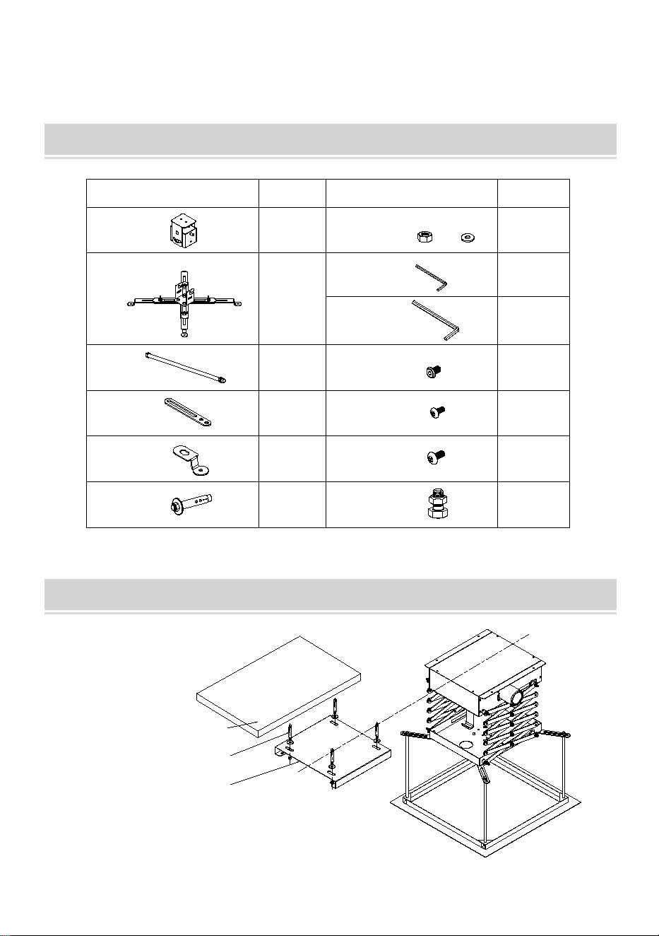
PACKAGE LIST
A:
B:
C:
D:
E:
F:M8*70
G:M4
H:M3
I:M4
J:M4*10
1 pcs
1 pcs
4 pcs
4 pcs
2 pcs
4 pcs
1 pcs
1 pcs
10 pcs
6 pcs
K:M3*12
4 pcs
L:M4*12
6 pcs
M:M8*16
4 pcs
Image
Quantity
Image
Quantity
Parts list:
ASSEMBLY STEP
Cement ceiling
Bolts
mounting plate,
fixed to the celing

4
Wir empfehlen Ihnen, Strommasten in der folgenden Reihenfolge zu
installieren:
Bestimmen Sie anhand der Brennweite der Bildschirmgröße und des
Abstands zwischen Aufhänger und Bildschirm des Projektors einen
geeigneten Aufhänger-Installationsort. Das Installationsloch in der
Deckenaufhängerplatte muss der Größe entsprechen. Gleichzeitig wird
empfohlen, die Installationsposition auf der Wartungsseite des Lochs (40 x
40 cm) zu reservieren.
Nach dem Anbringen der Löcher an der Decke messen Sie den
Mittenabstand der Löcher für die Montageplatte der vier Laufschienen (211
x 225 mm). Um die Löcher an der Decke zu befestigen, platzieren Sie die
vier M10 x 80-Schrauben an der Decke.
3. Die Schrauben in die Montageplatte einsetzen und die Mutter
festziehen, damit die Montageplatte an der Decke befestigt werden kann.
4. Den Aufhänger in die Montageplatte einsetzen. Mit vier M5 x 12 mm
Schrauben zwischen Aufhänger und Montageplatte verschrauben.
5. Stecken Sie die Fernbedienung ein, indem Sie sie ausschalten. Der
Kleiderbügel wird werkseitig eingestellt und läuft zur nächsten Fahrt. Wenn
Sie zur nächsten Fahrt laufen, läuft der Kleiderbügel nicht mehr.
6. Nach der Installation des Projektors befestigen Sie die Grundplatte
und den Aufhänger mit vier M8-Schrauben. Die mitgelieferte
Universalhalterung wird mit einer M6-Schraube an der
Scherenmontageplatte befestigt.
7. Passen Sie die Auslösung der Strommasten entsprechend der
Höhe des Bildschirms an. Anpassungsmethode:

5
Loosen the screws
slightly,moving the
location of this block.
Lösen Sie mit einem Schraubendreher die Schrauben des
Hubpositionierungsblocks (rechts) leicht (nicht abschrauben). Verschieben
Sie diese Position leicht nach links und ziehen Sie die Schrauben fest.
Lassen Sie die Aufhängung laufen und beobachten Sie die nach unten
gerichtete Position. Wiederholen Sie diesen Vorgang, bis Sie eine
geeignete Höhe für die Bildschirmaufhängung gefunden haben. Stellen Sie
die Obergrenze ein, lösen Sie den ganz linken Hubpositionierungsblock
und ziehen Sie die Schrauben nach rechts fest. Lassen Sie die
Aufhängung laufen und beobachten Sie die nach oben gerichtete Position.
Wiederholen Sie diesen Vorgang, bis Sie eine geeignete Höhe für die
Bildschirmaufhängung gefunden haben. Hinweis: Nach dem Einstellen der
Ober- und Untergrenze müssen wir die Befestigungsschrauben festziehen,
da es sonst während des Vorgangs zur Positionierung der Aufhängung und
zum Verschieben der Position kommt. Lassen Sie bei einer
2-m-Aufhängung die Schere beim Einstellen der Obergrenze nicht
vollständig einfahren. (Damit der Motor nicht stoppt.)


7
RECOVERY AND DISPOSAL
Dieses Produkt entspricht den Bestimmungen der europäischen Richtlinie
2012/19/EG. Das Symbol einer durchgestrichenen Mülltonne weist darauf
hin, dass dieses Produkt in der EU separat recycelt werden muss.
Gleiches gilt für Produkte und sämtliches Zubehör, die mit diesem Symbol
gekennzeichnet sind. Produkte, die als solche gekennzeichnet sind, dürfen
nicht mit dem normalen Hausmüll entsorgt werden. Hausmüll, sondern
muss an einer Sammelstelle für das Recycling von elektrischen und
elektronischen Geräten abgegeben werden.
Modell
TLMPL- 1,5 M
Leistung
38 W
Stromspannung
110-120 V
Wechselstrom, 60 Hz
220-240 V Wechselstrom,
50 Hz
Maximales Ladegewicht
Max 15 kg
(Es wird empfohlen, es bis zu einer Belastung von
10 kg zu verwenden.)
Produktgröße
343*315*2 15 mm
Teleskophub
Max: 1,5 m

8
Richtige Entsorgung
Dieses Produkt unterliegt den Bestimmungen der europäischen Richtlinie
2012/19/EU. Das Symbol einer durchgestrichenen Mülltonne weist darauf
hin, dass dieses Produkt in der Europäischen Union einer getrennten
Müllentsorgung unterliegt. Dies gilt für das Produkt und alle mit diesem
Symbol gekennzeichneten Zubehörteile. So gekennzeichnete Produkte
dürfen nicht im normalen Hausmüll entsorgt werden, sondern müssen an
einer Sammelstelle für das Recycling von elektrischen und elektronischen
Geräten abgegeben werden.
FCC-Informationen:
ACHTUNG: Durch Änderungen oder Modifikationen, die nicht ausdrücklich
von der für die Konformität verantwortlichen Partei genehmigt wurden,
kann die Berechtigung des Benutzers zum Betrieb des Geräts erlöschen!
Dieses Gerät entspricht Teil 15 der FCC-Bestimmungen. Der Betrieb
unterliegt den folgenden zwei Bedingungen:
1) Dieses Produkt kann schädliche Störungen verursachen.
2) Dieses Produkt muss alle empfangenen Störungen tolerieren,
einschließlich Störungen, die einen unerwünschten Betrieb verursachen
können.
WARNUNG: Änderungen oder Modifikationen an diesem Produkt, die nicht
ausdrücklich von der für die Konformität verantwortlichen Partei genehmigt
wurden, können zum Erlöschen der Berechtigung des Benutzers zum
Betrieb des Produkts führen.
Hinweis: Dieses Produkt wurde getestet und entspricht den Grenzwerten
für digitale Geräte der Klasse B gemäß Teil 15 der FCC-Bestimmungen.
Diese Grenzwerte sollen einen angemessenen Schutz gegen schädliche
Störungen bei der Installation in Wohngebieten bieten.
Dieses Produkt erzeugt und verwendet Hochfrequenzenergie und kann

9
diese auch ausstrahlen. Wenn es nicht gemäß den Anweisungen installiert
und verwendet wird, kann es zu Störungen des Funkverkehrs kommen. Es
gibt jedoch keine Garantie dafür, dass bei einer bestimmten Installation
keine Störungen auftreten. Wenn dieses Produkt Störungen des Radio-
oder Fernsehempfangs verursacht (was durch Ein- und Ausschalten des
Produkts festgestellt werden kann), wird dem Benutzer empfohlen, die
Störungen durch eine oder mehrere der folgenden Maßnahmen zu
beheben.
· Empfangsantenne neu ausrichten oder verlegen.
· Vergrößern Sie den Abstand zwischen Produkt und Empfänger.
· Schließen Sie das Produkt an eine Steckdose eines anderen
Stromkreises an als den, an den der Empfänger angeschlossen ist.
· Wenden Sie sich an den Händler oder einen erfahrenen
Radio-/Fernsehtechniker.

10


Tecnico Supporto e certificato di garanzia elettronica
www.vevor.com/support
SOLLEVATORE MOTORIZZATO PER
PROIETTORI
MANUALE D' uso
MODELLO: TLMPL-1M , TLMPL-1.5M
We continue to be committed to provide you tools with competitive price.
"Save Half", "Half Price" or any other similar expressions used by us only represents an
estimate of savings you might benefit from buying certain tools with us compared to the major
top brands and does not necessarily mean to cover all categories of tools offered by us. You
are kindly reminded to verify carefully when you are placing an order with us if you are
actually saving half in comparison with the top major brands.


1
MODELLO: TLMPL-1M, TLMPL-1.5M
Have product questions? Need technical support? Please feel free to
contact us:
Technical Support and E-Warranty Certificate
www.vevor.com/support
NEED HELP? CONTACT US!
This is the original instruction, please read all manual instructions
carefully before operating. VEVOR reserves a clear interpretation of our
user manual. The appearance of the product shall be subject to the
product you received. Please forgive us that we won't inform you again if
there are any technology or software updates on our product.
MOTORIZED PROJECTOR LIFT

2
SAFETY INSTRUCTIONS
AVVERTIMENTO:
Leggere questo materiale prima di utilizzare questo prodotto. In caso
contrario si potrebbero causare lesioni gravi.
Precauzioni per il montaggio
17. Assemblare solo secondo queste istruzioni. Un montaggio improprio
può creare pericoli.
18. Indossare occhiali di sicurezza e guanti da lavoro durante il
montaggio.
19. Mantenere l'area di assemblaggio pulita e ben illuminata.
20. Tenere gli astanti lontani dall'area durante il montaggio.
21. Non montare in caso di stanchezza o sotto l'effetto di alcol, droghe o
farmaci.
22. Le funzionalità del prodotto si applicano solo ai prodotti correttamente
e completamente assemblati.
23. Montare su una superficie piana, livellata, dura e liscia in grado di
supportare in sicurezza il sollevatore motorizzato del proiettore .
24. Per ulteriori informazioni riguardanti le parti elencate nelle pagine
seguenti, fare riferimento allo Schema di Montaggio di questo manuale.
Scartare e separare tutte le parti in un'area di lavoro pulita.
Usare precauzioni
13. NON SEDERSI O STARE IN PIEDI SU QUESTO ARTICOLO.
14. Questo prodotto non è un giocattolo. Non permettere ai bambini di
giocare con o vicino a questo oggetto.
15. Non superare la capacità di peso.
16. Utilizzare solo su una superficie piana, livellata, dura e liscia in grado
di supportare in sicurezza un sollevatore motorizzato per proiettori a
pieno carico .
17. Utilizzare solo come previsto.
18. Ispezionare prima di ogni utilizzo; non utilizzare se le parti sono
allentate o danneggiate.

3
CONSERVA QUESTO MANUALE
PACKAGE LIST
A:
B:
C:
D:
E:
F:M8*70
G:M4
H:M3
I:M4
J:M4*10
1 pcs
1 pcs
4 pcs
4 pcs
2 pcs
4 pcs
1 pcs
1 pcs
10 pcs
6 pcs
K:M3*12
4 pcs
L:M4*12
6 pcs
M:M8*16
4 pcs
Image
Quantity
Image
Quantity
Parts list:
ASSEMBLY STEP
Cement ceiling
Bolts
mounting plate,
fixed to the celing
Ti consigliamo di installare i tralicci elettrici nel seguente ordine:

4
In base alla lunghezza focale delle dimensioni dello schermo e al
proiettore, si determina la distanza tra il gancio e lo schermo, impostare
una buona posizione di installazione del gancio. Il foro di installazione nella
piastra di sospensione a soffitto in base alle dimensioni. Nel frattempo,
posizione di installazione consigliata riservata al lato manutenzione del
foro(40*40 cm)
Dopo aver eseguito correttamente i fori di montaggio sul soffitto,
misurando l'interasse dei fori della piastra di montaggio delle quattro piste
(211 * 225 mm), per prevalere sul soffitto con l'impatto della perforazione,
la distribuzione dei quattro bulloni M10 * 80 incorporati nel soffitto.
3、La piastra di montaggio viene inserita con i bulloni e serrare il dado
sulla piastra di montaggio fissata al soffitto.
4、 Il gancio nella piastra di montaggio. Con quattro M5 * 12 mm
avvitati tra il gancio e la piastra di montaggio.
5、 Collegare il telecomando e alimentarlo abbassandolo. Hanger
allestito in fabbrica, il prossimo viaggio. Corri al prossimo viaggio, smettila
di correre.
6、Dopo aver installato il proiettore, collegare la piastra di base e il
gancio con quattro viti M8. Piastra di montaggio a forbice con bulloni M6
installata con la consegna della testa universale.
7、In base all'altezza dello schermo, regolare lo scatto dei tralicci
elettrici. Metodo di regolazione:
5
Loosen the screws
slightly,moving the
location of this block.
Utilizzare un cacciavite per allentare leggermente le viti del diagramma a
blocchi di posizionamento della corsa (a destra) (per non svitarle), questa
posizione è leggermente spostata sul blocco sinistro, serrare le viti. Esegui
il gancio, il gancio osserva la posizione a valle. Ripeti questa azione fino a
trovare un'altezza adatta per il supporto dello schermo. Regolare il limite
superiore, rilasciare il blocco di posizionamento della corsa più a sinistra, a
destra, serrare le viti. Eseguire la gruccia, osservando la posizione della
gruccia verso l'alto. Ripeti questa azione fino a trovare un'altezza adatta
per il supporto dello schermo. Nota: dopo aver regolato il limite superiore e
inferiore, è necessario serrare le viti di fissaggio, altrimenti si verificherà
l'operazione di posizionamento del gancio e localizzazione della corsa. Per
il gancio 2M, quando si regola il limite superiore, non lasciare che le forbici
siano completamente collassate. (Quindi no, interrompe la funzione
motoria)
7
RECOVERY AND DISPOSAL
Questo prodotto è conforme alle disposizioni della Direttiva Europea
2012/19/CE. Il simbolo contrassegnato da un bidone della spazzatura
barrato indica che questo prodotto richiede un riciclaggio separato nell'UE.
Lo stesso vale per i prodotti e tutti gli accessori contrassegnati da questo
simbolo. I prodotti contrassegnati come tali non devono essere smaltiti
normalmente rifiuti domestici, ma devono essere portati in un punto di
raccolta per il riciclaggio di apparecchiature elettriche ed elettroniche.
Energia
38 W
Voltaggio
110-120 VCA 60 Hz
220-240 VCA 50 Hz
Peso massimo caricato
Massimo 15kg
(Si consiglia di utilizzare entro 10 kg di carico.)
Taglia del prodotto
343*315 * 215mm
Corsa telescopica
Massimo: 1,5 m

8
Corretto smaltimento
Questo prodotto è soggetto alle disposizioni della Direttiva europea
2012/19/UE. Il simbolo del bidone della spazzatura barrato indica che
nell'Unione Europea il prodotto richiede la raccolta differenziata dei rifiuti.
Ciò vale per il prodotto e tutti gli accessori contrassegnati da questo
simbolo. I prodotti contrassegnati come tali non possono essere smaltiti
con i normali rifiuti domestici, ma devono essere portati in un punto di
raccolta per il riciclaggio di dispositivi elettrici ed elettronici.
Informazioni FCC:
ATTENZIONE: cambiamenti o modifiche non espressamente approvati
dalla parte responsabile della conformità potrebbero invalidare il diritto
dell'utente a utilizzare l'apparecchiatura!
Questo dispositivo è conforme alla Parte 15 delle norme FCC. Il
funzionamento è soggetto alle seguenti due condizioni:
1) Questo prodotto può causare interferenze dannose.
2) Questo prodotto deve accettare qualsiasi interferenza ricevuta,
comprese le interferenze che potrebbero causare un funzionamento
indesiderato.
AVVERTENZA: cambiamenti o modifiche a questo prodotto non
espressamente approvati dalla parte responsabile della conformità
potrebbero annullare l'autorità dell'utente a utilizzare il prodotto.
Nota: questo prodotto è stato testato ed è risultato conforme ai limiti per un
dispositivo digitale di Classe B ai sensi della Parte 15 delle norme FCC.
Questi limiti sono progettati per fornire una protezione ragionevole contro
interferenze dannose in un'installazione residenziale.
Questo prodotto genera, utilizza e può irradiare energia in radiofrequenza
e, se non installato e utilizzato in conformità con le istruzioni, può causare
interferenze dannose alle comunicazioni radio. Tuttavia, non vi è alcuna
garanzia che non si verifichino interferenze in una particolare installazione.
Se questo prodotto causa interferenze dannose alla ricezione radiofonica o
televisiva, cosa che può essere determinata spegnendo e accendendo il
prodotto, si consiglia all'utente di provare a correggere l'interferenza
adottando una o più delle seguenti misure.

9
· Riorientare o riposizionare l'antenna ricevente.
· Aumentare la distanza tra il prodotto e il ricevitore.
· Collegare il prodotto ad una presa su un circuito diverso da quello a cui è
collegato il ricevitore.
· Consultare il rivenditore o un tecnico radio/TV esperto per assistenza.


Técnico Certificado de soporte y garantía electrónica
www.vevor.com/support
ELEVADOR DE PROYECTOR
MOTORIZADO
de USUARIO
MODELO: TLMPL-1M , TLMPL-1.5M
We continue to be committed to provide you tools with competitive price.
"Save Half", "Half Price" or any other similar expressions used by us only represents an
estimate of savings you might benefit from buying certain tools with us compared to the major
top brands and does not necessarily mean to cover all categories of tools offered by us. You
are kindly reminded to verify carefully when you are placing an order with us if you are
actually saving half in comparison with the top major brands.


1
MODELO: TLMPL-1M, TLMPL-1.5M
Have product questions? Need technical support? Please feel free to
contact us:
Technical Support and E-Warranty Certificate
www.vevor.com/support
NEED HELP? CONTACT US!
This is the original instruction, please read all manual instructions
carefully before operating. VEVOR reserves a clear interpretation of our
user manual. The appearance of the product shall be subject to the
product you received. Please forgive us that we won't inform you again if
there are any technology or software updates on our product.
MOTORIZED PROJECTOR LIFT

2
SAFETY INSTRUCTIONS
ADVERTENCIA:
Lea este material antes de usar este producto. De lo contrario, se
pueden producir lesiones graves.
Precauciones de montaje
25. Ensamble únicamente de acuerdo con estas instrucciones. Un
montaje inadecuado puede crear peligros.
26. Utilice gafas de seguridad y guantes de trabajo durante el montaje.
27. Mantenga el área de reunión limpia y bien iluminada.
28. Mantenga a los transeúntes fuera del área durante el montaje.
29. No se reúna cuando esté cansado o bajo la influencia de alcohol,
drogas o medicamentos.
30. Las capacidades del producto se aplican únicamente a productos
ensamblados de manera adecuada y completa.
31. Ensamble sobre una superficie plana, nivelada, dura y lisa capaz de
soportar de manera segura el elevador motorizado del proyector .
32. Para obtener información adicional sobre las piezas enumeradas en
las siguientes páginas, consulte el diagrama de montaje de este manual.
Desenvuelva y separe todas las piezas en un área de trabajo limpia.
Use precauciones
19. NO SE SIENTE NI SE PARE SOBRE ESTE ARTÍCULO.
20. Este producto no es un juguete. No permita que los niños jueguen con
este artículo o cerca de él.
21. No exceda las capacidades de peso.
22. Úselo únicamente sobre una superficie plana, nivelada, dura y lisa
capaz de soportar de manera segura un elevador de proyector
motorizado completamente cargado .
23. Úselo únicamente según lo previsto.
24. Inspeccionar antes de cada uso; no lo utilice si las piezas están
sueltas o dañadas.
3
GUARDE ESTE MANUAL
PACKAGE LIST
A:
B:
C:
D:
E:
F:M8*70
G:M4
H:M3
I:M4
J:M4*10
1 pcs
1 pcs
4 pcs
4 pcs
2 pcs
4 pcs
1 pcs
1 pcs
10 pcs
6 pcs
K:M3*12
4 pcs
L:M4*12
6 pcs
M:M8*16
4 pcs
Image
Quantity
Image
Quantity
Parts list:
ASSEMBLY STEP
Cement ceiling
Bolts
mounting plate,
fixed to the celing
Le recomendamos que instale torres eléctricas en el siguiente orden:

4
Según la distancia focal del tamaño de la pantalla y el proyector, se
determina la distancia entre el colgador y la pantalla, establezca una
buena ubicación para la instalación del colgador. El orificio de instalación
en la placa para colgar del techo según el tamaño. Mientras tanto, la
posición de instalación recomendada está reservada para el lado de
mantenimiento del orificio (40*40 cm)
Después de realizar buenos orificios de montaje en el techo, mida la
distancia entre centros de los cuatro orificios de la placa de montaje de las
pistas (211 * 225 mm), para prevalecer en el techo con el impacto de la
perforación, la distribución de los cuatro pernos M10 * 80 incrustados en el
techo.
3. La placa de montaje se inserta con pernos y aprieta la tuerca en la
placa de montaje que se fija al techo.
4、 El colgador en la placa de montaje. Con cuatro tornillos M5*12mm
entre el colgador y la placa de montaje.
5. Conecte el control remoto y se apague. Instalación de la fábrica de
perchas, el próximo viaje. Corre al siguiente viaje, deja de correr.
6、Después de instalar el proyector, utilice cuatro tornillos M8 para
conectar la placa base y el soporte. Placa de montaje de tijeras con pernos
M6 instalada con la entrega de cabezal universal.
7. Según la altura de la pantalla, ajuste el recorrido de las torres
eléctricas. Método de ajuste:

5
Loosen the screws
slightly,moving the
location of this block.
Utilice un destornillador para aflojar ligeramente los tornillos del diagrama
de bloques de posicionamiento de carrera (a la derecha) (no para
desenroscar), esta posición se desplaza ligeramente hacia el bloque
izquierdo, apriete los tornillos. Ejecute el hangar, el hangar observó la
ubicación aguas abajo. Repita esta acción hasta encontrar una altura
adecuada para colgar la pantalla. Ajuste el límite superior, suelte el bloque
de posicionamiento de carrera más a la izquierda, hacia la derecha,
apriete los tornillos. Ejecute la percha, la percha observa la posición hacia
arriba. Repita esta acción hasta encontrar una altura adecuada para colgar
la pantalla. Nota: Después de ajustar el límite superior e inferior, debemos
apretar los tornillos de fijación, de lo contrario, ocurrirá en la operación de
posicionamiento del colgador y localización del funcionamiento. Para
perchas de 2M, al ajustar el límite superior, no deje que las tijeras
colapsen por completo. (Entonces no, detiene la función motora)
7
RECOVERY AND DISPOSAL
Este producto cumple con las disposiciones de la Directiva Europea
2012/19/CE. El símbolo marcado con un contenedor con ruedas tachado
indica que este producto requiere reciclaje por separado en la UE. Lo
mismo se aplica a los productos y todos los accesorios marcados con este
símbolo. Los productos marcados como tales no deben eliminarse con los
medios normales. residuos domésticos, pero deben llevarse a un punto de
recogida para el reciclaje de aparatos eléctricos y electrónicos.
Modelo
TLMPL - 1.5M
Fuerza
38W
Voltaje
110-120 VCA 60 Hz
220-240 VCA 50 Hz
Peso máximo con carga
Máximo 15 kg
(Se recomienda utilizar dentro de los 10 kg de
carga).
Tamaño del producto
343*315* 2 15mm
Carrera telescópica
Máximo: 1,5 m

8
Eliminación correcta
Este producto está sujeto a las disposiciones de la Directiva europea
2012/19/UE. El símbolo que muestra un contenedor con ruedas tachado
indica que el producto requiere recogida selectiva de basura en la Unión
Europea. Esto se aplica al producto y a todos los accesorios marcados con
este símbolo. Los productos marcados como tales no podrán desecharse
junto con la basura doméstica normal, sino que deberán llevarse a un
punto de recogida para el reciclaje de aparatos eléctricos y electrónicos.
Información de la FCC:
PRECAUCIÓN: ¡ Los cambios o modificaciones no aprobados
expresamente por la parte responsable del cumplimiento podrían anular la
autoridad del usuario para operar el equipo!
Este dispositivo cumple con la Parte 15 de las normas de la FCC. La
operación está sujeta a las dos condiciones siguientes:
1) Este producto puede causar interferencias perjudiciales.
2) Este producto debe aceptar cualquier interferencia recibida, incluidas
las interferencias que puedan causar un funcionamiento no deseado.
ADVERTENCIA: Los cambios o modificaciones a este producto que no
estén aprobados expresamente por la parte responsable del cumplimiento
podrían anular la autoridad del usuario para operar el producto.
Nota: Este producto ha sido probado y cumple con los límites para un
dispositivo digital Clase B de conformidad con la Parte 15 de las reglas de
la FCC. Estos límites están diseñados para brindar una protección
razonable contra interferencias dañinas en una instalación residencial.
Este producto genera, usa y puede irradiar energía de radiofrecuencia y, si
no se instala y usa de acuerdo con las instrucciones, puede causar
interferencias dañinas en las comunicaciones por radio. Sin embargo, no
hay garantía de que no se produzcan interferencias en una instalación en
particular. Si este producto causa interferencias dañinas en la recepción

9
de radio o televisión, lo cual se puede determinar apagando y
encendiendo el producto, se recomienda al usuario que intente corregir la
interferencia mediante una o más de las siguientes medidas.
· Reorientar o reubicar la antena receptora.
· Aumentar la distancia entre el producto y el receptor.
· Conecte el producto a una toma de corriente de un circuito diferente al
que está conectado el receptor.
· Consulte al distribuidor o a un técnico experimentado en radio/TV para
obtener ayuda.

10


Techniczny Certyfikat wsparcia i e-gwarancji
www.vevor.com/support
ZMOTORYZOWANY PODNOŚNIK DO
PROJEKTORA
INSTRUKCJA obsługi
MODEL: TLMPL-1M , TLMPL-1,5M
We continue to be committed to provide you tools with competitive price.
"Save Half", "Half Price" or any other similar expressions used by us only represents an
estimate of savings you might benefit from buying certain tools with us compared to the major
top brands and does not necessarily mean to cover all categories of tools offered by us. You
are kindly reminded to verify carefully when you are placing an order with us if you are
actually saving half in comparison with the top major brands.


1
MODEL: TLMPL-1M, TLMPL-1,5M
Have product questions? Need technical support? Please feel free to
contact us:
Technical Support and E-Warranty Certificate
www.vevor.com/support
NEED HELP? CONTACT US!
This is the original instruction, please read all manual instructions
carefully before operating. VEVOR reserves a clear interpretation of our
user manual. The appearance of the product shall be subject to the
product you received. Please forgive us that we won't inform you again if
there are any technology or software updates on our product.
MOTORIZED PROJECTOR LIFT

2
SAFETY INSTRUCTIONS
OSTRZEŻENIE:
Przeczytaj ten materiał przed użyciem tego produktu.
Niezastosowanie się do tego może spowodować poważne obrażenia.
Środki ostrożności podczas montażu
33. Montaż wyłącznie zgodnie z niniejszą instrukcją. Nieprawidłowy
montaż może stworzyć zagrożenie.
34. Podczas montażu należy nosić okulary ochronne i rękawice robocze.
35. Utrzymuj miejsce zbiórki w czystości i dobrze oświetlone.
36. Podczas montażu trzymaj osoby postronne z dala od obszaru.
37. Nie należy montować, gdy jest się zmęczonym lub pod wpływem
alkoholu, narkotyków lub leków.
38. Możliwości produktu dotyczą wyłącznie produktów prawidłowo i
całkowicie zmontowanych.
39. Zmontuj na płaskiej, poziomej, twardej i gładkiej powierzchni, która
może bezpiecznie utrzymać podnośnik do projektora z napędem
silnikowym .
40. Dodatkowe informacje dotyczące części wymienionych na kolejnych
stronach można znaleźć w schemacie montażu w niniejszej instrukcji.
Rozpakuj i oddziel wszystkie części w czystym miejscu pracy.
Stosuj środki ostrożności
25. NIE SIEDŹ ANI NIE STAJ NA TYM PRZEDMIOCIE.
26. Ten produkt nie jest zabawką. Nie pozwalaj dzieciom bawić się tym
przedmiotem lub w jego pobliżu.
27. Nie przekraczaj dopuszczalnej masy.
28. Używaj wyłącznie na płaskiej, równej, twardej i gładkiej powierzchni,
która może bezpiecznie utrzymać w pełni obciążony zmotoryzowany
podnośnik do projektora .
29. Używaj wyłącznie zgodnie z przeznaczeniem.
30. Sprawdź przed każdym użyciem; nie używać, jeśli części są luźne lub
uszkodzone.
3
ZACHOWAJ TĘ INSTRUKCJĘ
PACKAGE LIST
A:
B:
C:
D:
E:
F:M8*70
G:M4
H:M3
I:M4
J:M4*10
1 pcs
1 pcs
4 pcs
4 pcs
2 pcs
4 pcs
1 pcs
1 pcs
10 pcs
6 pcs
K:M3*12
4 pcs
L:M4*12
6 pcs
M:M8*16
4 pcs
Image
Quantity
Image
Quantity
Parts list:
ASSEMBLY STEP
Cement ceiling
Bolts
mounting plate,
fixed to the celing
Zalecamy montaż słupów elektrycznych w następującej kolejności:

4
Na podstawie ogniskowej rozmiaru ekranu i projektora w oparciu o
określenie odległości pomiędzy wieszakiem a ekranem, należy ustawić
dobre miejsce montażu wieszaka. Otwór montażowy w płycie wieszaka
sufitowego w zależności od rozmiaru. Tymczasem zalecana pozycja
montażowa zarezerwowana dla strony otworu przeznaczonej do
konserwacji (40*40 cm)
Po dobrych otworach montażowych na suficie, zmierzeniu odległości
od środka czterech otworów w płycie montażowej pasów startowych (211 *
225 mm), aby wywrzeć wpływ na suficie pod wpływem wiercenia,
rozmieścić cztery śruby M10 * 80 osadzone w suficie.
3、W płycie montażowej włóż śruby i dokręć nakrętkę na płycie
montażowej przymocowanej do sufitu。
4. Wieszak w płycie montażowej. Z czterema śrubami M5 * 12 mm
wkręconymi pomiędzy wieszakiem a płytą montażową.
5. Podłącz pilota, aby był zasilany przez wyczerpanie. Fabryka
wieszaków założona, następna wyprawa. Biegnij do następnej podróży,
wieszak przestanie działać.
6. Po zainstalowaniu projektora, użyj czterech śrub M8 do połączenia
płyty podstawy i wieszaka. Śruby M6, płyta montażowa nożyczek
zainstalowana wraz z dostawą uniwersalnej głowicy.
7、W zależności od wysokości ekranu wyreguluj wyłączenie słupów
elektrycznych. Metoda regulacji:

5
Loosen the screws
slightly,moving the
location of this block.
Za pomocą śrubokręta lekko poluzować śruby blokowe pozycjonowania
skoku (po prawej) (nie odkręcać), pozycja ta jest lekko przesunięta do
lewego bloku, dokręcić śruby. Wieszak biegowy, wieszak obserwowany w
dalszej części rzeki. Powtarzaj tę czynność, aż znajdziesz odpowiednią
wysokość wieszaka na ekran. Ustaw górną granicę, zwolnij blokadę
pozycjonowania skoku skrajnie lewą, w prawo dokręć śruby. Uruchom
wieszak, wieszak obserwuje położenie do góry. Powtarzaj tę czynność, aż
znajdziesz odpowiednią wysokość wieszaka na ekran. Uwaga: Po
wyregulowaniu górnego i dolnego limitu należy dokręcić śruby mocujące,
w przeciwnym razie nastąpi operacja ułożenia wieszaka, lokalizacja biegu.
W przypadku wieszaka 2M, regulując górny limit, nie pozwól, aby nożyczki
całkowicie się opadły. (Więc nie, zatrzymuje funkcję silnika)

7
RECOVERY AND DISPOSAL
Ten produkt jest zgodny z postanowieniami Dyrektywy Europejskiej
2012/19/EC. Symbol oznaczony przekreślonym koszem na śmieci
oznacza, że ten produkt wymaga oddzielnego recyklingu w UE. To samo
dotyczy produktów i wszystkich akcesoriów oznaczonych tym symbolem.
Produktów oznaczonych jako takie nie wolno wyrzucać razem ze zwykłymi
odpadami odpady domowe, należy je jednak oddać do punktu zbiórki
sprzętu elektrycznego i elektronicznego przeznaczonego do recyklingu.
Moc
38 W
Napięcie
110-120VAC 60Hz
220-240 VVAC 50 Hz
Maksymalna masa
ładunku
Maks . 15 kg
(Zaleca się użycie w zakresie obciążenia 10 kg.)
Rozmiar produktu
343*315*2 15 mm
Skok teleskopowy
Maks.: 1,5 m

8
Prawidłowa utylizacja
Ten produkt podlega postanowieniom dyrektywy europejskiej 2012/19/UE.
Symbol przekreślonego kosza na śmieci oznacza, że produkt wymaga
selektywnej zbiórki śmieci na terenie Unii Europejskiej. Dotyczy to
produktu i wszystkich akcesoriów oznaczonych tym symbolem. Produktów
oznaczonych jako takie nie można wyrzucać razem ze zwykłymi odpadami
domowymi, lecz należy je przekazać do punktu zbiórki w celu recyklingu
urządzeń elektrycznych i elektronicznych.
Informacje FCC:
UWAGA: Zmiany lub modyfikacje, które nie zostały wyraźnie zatwierdzone
przez stronę odpowiedzialną za zgodność, mogą unieważnić uprawnienia
użytkownika do obsługi urządzenia!
To urządzenie jest zgodne z częścią 15 przepisów FCC. Działanie podlega
następującym dwóm warunkom:
1) Ten produkt może powodować szkodliwe zakłócenia.
2) Ten produkt musi akceptować wszelkie odbierane zakłócenia, w tym
zakłócenia, które mogą powodować niepożądane działanie.
OSTRZEŻENIE: Zmiany lub modyfikacje tego produktu, które nie zostały
wyraźnie zatwierdzone przez stronę odpowiedzialną za zgodność, mogą
unieważnić uprawnienia użytkownika do obsługi produktu.
Uwaga: ten produkt został przetestowany i stwierdzono, że spełnia
ograniczenia dla urządzeń cyfrowych klasy B zgodnie z częścią 15
przepisów FCC. Ograniczenia te mają na celu zapewnienie rozsądnej
ochrony przed szkodliwymi zakłóceniami w instalacjach domowych.
Ten produkt generuje, wykorzystuje i może emitować energię o
częstotliwości radiowej, a jeśli nie zostanie zainstalowany i nie będzie
używany zgodnie z instrukcją, może powodować szkodliwe zakłócenia w
komunikacji radiowej. Nie ma jednak gwarancji, że w konkretnej instalacji
nie wystąpią zakłócenia. Jeśli produkt powoduje szkodliwe zakłócenia w
odbiorze radia lub telewizji, co można stwierdzić poprzez wyłączenie i
włączenie produktu, zachęca się użytkownika do podjęcia próby
skorygowania zakłóceń za pomocą jednego lub kilku z poniższych

9
środków.
· Zmień orientację lub położenie anteny odbiorczej.
· Zwiększ odległość pomiędzy produktem a odbiornikiem.
· Podłącz produkt do gniazdka w innym obwodzie niż ten, do którego
podłączony jest odbiornik.
· Skonsultuj się ze sprzedawcą lub doświadczonym technikiem
radiowo-telewizyjnym w celu uzyskania pomocy.


Technisch Ondersteuning en e-garantiecertificaat
www.vevor.com/support
GEMOTORISEERDE PROJECTORLIFT
Handleiding
MODEL: TLMPL-1M , TLMPL-1.5M
We continue to be committed to provide you tools with competitive price.
"Save Half", "Half Price" or any other similar expressions used by us only represents an
estimate of savings you might benefit from buying certain tools with us compared to the major
top brands and does not necessarily mean to cover all categories of tools offered by us. You
are kindly reminded to verify carefully when you are placing an order with us if you are
actually saving half in comparison with the top major brands.


1
MODEL: TLMPL-1M, TLMPL-1.5M
Have product questions? Need technical support? Please feel free to
contact us:
Technical Support and E-Warranty Certificate
www.vevor.com/support
NEED HELP? CONTACT US!
This is the original instruction, please read all manual instructions
carefully before operating. VEVOR reserves a clear interpretation of our
user manual. The appearance of the product shall be subject to the
product you received. Please forgive us that we won't inform you again if
there are any technology or software updates on our product.
MOTORIZED PROJECTOR LIFT

2
SAFETY INSTRUCTIONS
WAARSCHUWING:
Lees dit materiaal voordat u dit product gebruikt. Als u dit niet doet,
kan dit leiden tot ernstig letsel.
Voorzorgsmaatregelen voor montage
41. Monteer uitsluitend volgens deze instructies. Onjuiste montage kan
gevaren veroorzaken.
42. Draag tijdens de montage een veiligheidsbril en werkhandschoenen.
43. Houd de verzamelplaats schoon en goed verlicht.
44. Houd omstanders tijdens de montage uit de buurt.
45. Niet monteren als u moe bent of onder invloed bent van alcohol, drugs
of medicijnen.
46. De productmogelijkheden zijn alleen van toepassing op correct en
volledig gemonteerde producten.
47. Monteer op een vlakke, vlakke, harde en gladde ondergrond die de
gemotoriseerde projectorlift veilig kan ondersteunen .
48. Voor aanvullende informatie over de onderdelen die op de volgende
pagina's worden vermeld, verwijzen wij u naar het montageschema van
deze handleiding. Pak alle onderdelen uit en scheid ze van elkaar op
een schone werkplek.
Gebruik voorzorgsmaatregelen
31. ZIT OF STA NIET OP DIT ITEM.
32. Dit product is geen speelgoed. Laat kinderen niet met of in de buurt
van dit artikel spelen.
33. Overschrijd de gewichtscapaciteiten niet.
34. Uitsluitend gebruiken op een vlakke, vlakke, harde en gladde
ondergrond die een volledig beladen gemotoriseerde projectorlift veilig
kan ondersteunen .
35. Alleen gebruiken zoals bedoeld.
36. Inspecteer vóór elk gebruik; niet gebruiken als onderdelen los of
beschadigd zijn.

3
BEWAAR DEZE HANDLEIDING
PACKAGE LIST
A:
B:
C:
D:
E:
F:M8*70
G:M4
H:M3
I:M4
J:M4*10
1 pcs
1 pcs
4 pcs
4 pcs
2 pcs
4 pcs
1 pcs
1 pcs
10 pcs
6 pcs
K:M3*12
4 pcs
L:M4*12
6 pcs
M:M8*16
4 pcs
Image
Quantity
Image
Quantity
Parts list:
ASSEMBLY STEP
Cement ceiling
Bolts
mounting plate,
fixed to the celing

4
Wij raden u aan om elektriciteitsmasten in de volgende volgorde te
installeren:
Door de brandpuntsafstand van de schermgrootte en de projector is
gebaseerd op het bepalen van de afstand tussen de hanger en het scherm,
stel een goede installatielocatie voor de hanger in. Het installatiegat in de
plafondhangerplaat volgens maat. Ondertussen aanbevolen
installatiepositie gereserveerd voor de onderhoudskant van het gat (40 *
40 cm)
Na goede montagegaten aan het plafond, meting van de vier gaten in
de middenafstand van de montageplaat van de start- en landingsbanen
(211 * 225 mm), om de impact van het boren op het plafond te overheersen,
wordt de verdeling van de vier M10 * 80 bouten ingebed in het plafond
uitgevoerd.
3. De montageplaat is voorzien van bouten en draai de moer op de
montageplaat vast aan het plafond.
4. De hanger in de montageplaat. Met vier M5 * 12 mm geschroefd
tussen de hanger en montageplaat.
5. Sluit de afstandsbediening aan als deze leeg is. Hangerfabriek
opgezet, de volgende reis. Ren naar de volgende reis, de hanger stopt met
rennen.
6. Na installatie van de projector, met vier M8-schroeven om de
basisplaat en de hanger te verbinden. M6-bouten schaarmontageplaat
geïnstalleerd bij levering van universele kop.
7. Pas de uitschakeling van de elektrische masten aan, afhankelijk
van de hoogte van het scherm. Aanpassingsmethode:

5
Loosen the screws
slightly,moving the
location of this block.
Gebruik een schroevendraaier om de schroeven van het
slagpositioneringsblokdiagram (aan de rechterkant) iets los te draaien (niet
om ze af te schroeven), deze positie is iets verschoven naar het linkerblok,
draai de schroeven vast. Run hanger, hanger waargenomen
stroomafwaartse locatie. Herhaal deze actie totdat u een geschikte
schermhangerhoogte heeft gevonden. Pas de bovenlimiet aan, laat het
meest linkse slagpositioneringsblok los, naar rechts, draai de schroeven
vast. Renhanger, hanger waargenomen opwaartse positie. Herhaal deze
actie totdat u een geschikte schermhangerhoogte heeft gevonden.
Opmerking: na het afstellen van de boven- en onderlimiet moeten we de
bevestigingsschroeven vastdraaien, anders zal dit optreden bij de
positionering van de hanger, lokalisatie van hardlopen. Laat bij het
afstellen van de bovengrens bij een 2M-hanger de schaar niet volledig
inklappen. (Dus nee, het stopt de motorische functie)


7
RECOVERY AND DISPOSAL
Dit product voldoet aan de bepalingen van de Europese Richtlijn
2012/19/EG. Het symbool gemarkeerd met een doorgekruiste afvalbak
geeft aan dat dit product in de EU afzonderlijk moet worden gerecycled.
Hetzelfde geldt voor producten en alle accessoires die met dit symbool zijn
gemarkeerd. Producten die als zodanig zijn gemarkeerd mogen niet bij het
normale afval worden weggegooid huishoudelijk afval, maar moet naar
een inzamelpunt voor recycling van elektrische en elektronische
apparatuur worden gebracht.
Model
TLMPL-1 .5 M
Stroom
38 W
Spanning
110-120VAC 60Hz
220-240 VVAC 50 Hz
Maximaal geladen
gewicht
Maximaal 15kg
(Het wordt aanbevolen om te gebruiken binnen een
belasting van 10 kg.)
Product grootte
343*315*2 15 mm
Telescopische slag
Maximaal: 1,5 meter

8
Correcte verwijdering
Dit product valt onder de bepalingen van de Europese Richtlijn 2012/19/EU.
Het symbool met een doorgestreepte afvalcontainer geeft aan dat het
product in de Europese Unie een aparte afvalinzameling vereist. Dit geldt
voor het product en alle accessoires die met dit symbool zijn gemarkeerd.
Producten die als zodanig zijn gemarkeerd, mogen niet bij het normale
huisvuil worden weggegooid, maar moeten worden ingeleverd bij een
inzamelpunt voor recycling van elektrische en elektronische apparaten.
FCC-informatie:
LET OP: Wijzigingen of aanpassingen die niet uitdrukkelijk zijn
goedgekeurd door de partij die verantwoordelijk is voor naleving kunnen de
bevoegdheid van de gebruiker om de apparatuur te bedienen ongeldig
maken!
Dit apparaat voldoet aan Deel 15 van de FCC-regels. De werking is
onderworpen aan de volgende twee voorwaarden:
1) Dit product kan schadelijke interferentie veroorzaken.
2) Dit product moet alle ontvangen interferentie accepteren, inclusief
interferentie die een ongewenste werking kan veroorzaken.
WAARSCHUWING: Wijzigingen of aanpassingen aan dit product die niet
uitdrukkelijk zijn goedgekeurd door de partij die verantwoordelijk is voor
naleving kunnen de bevoegdheid van de gebruiker om het product te
bedienen ongeldig maken.
Opmerking: Dit product is getest en voldoet aan de limieten voor een
digitaal apparaat van Klasse B overeenkomstig Deel 15 van de FCC-regels.
Deze limieten zijn bedoeld om redelijke bescherming te bieden tegen
schadelijke interferentie in een residentiële installatie.
Dit product genereert, gebruikt en kan radiofrequentie-energie uitstralen,
en als het niet wordt geïnstalleerd en gebruikt in overeenstemming met de

9
instructies, kan het schadelijke interferentie aan radiocommunicatie
veroorzaken. Er is echter geen garantie dat er geen interferentie zal
optreden in een bepaalde installatie. Als dit product schadelijke
interferentie veroorzaakt aan radio- of televisieontvangst, wat kan worden
vastgesteld door het product uit en weer in te schakelen, wordt de
gebruiker aangeraden te proberen de interferentie te corrigeren door een
of meer van de volgende maatregelen.
· Heroriënteer of verplaats de ontvangstantenne.
· Vergroot de afstand tussen het product en de ontvanger.
· Sluit het product aan op een stopcontact op een ander circuit dan dat
waarop de ontvanger is aangesloten.
· Raadpleeg de dealer of een ervaren radio-/tv-technicus voor hulp.

10


Teknisk Support och e-garanticertifikat
www.vevor.com/support
MOTORISERAD PROJEKTORLYFT
Användarmanual
MODELL: TLMPL-1M , TLMPL-1,5M
We continue to be committed to provide you tools with competitive price.
"Save Half", "Half Price" or any other similar expressions used by us only represents an
estimate of savings you might benefit from buying certain tools with us compared to the major
top brands and does not necessarily mean to cover all categories of tools offered by us. You
are kindly reminded to verify carefully when you are placing an order with us if you are
actually saving half in comparison with the top major brands.


1
MODELL: TLMPL-1M, TLMPL-1,5M
Have product questions? Need technical support? Please feel free to
contact us:
Technical Support and E-Warranty Certificate
www.vevor.com/support
NEED HELP? CONTACT US!
This is the original instruction, please read all manual instructions
carefully before operating. VEVOR reserves a clear interpretation of our
user manual. The appearance of the product shall be subject to the
product you received. Please forgive us that we won't inform you again if
there are any technology or software updates on our product.
MOTORIZED PROJECTOR LIFT

2
SAFETY INSTRUCTIONS
VARNING:
Läs detta material innan du använder denna produkt. Underlåtenhet
att göra det kan resultera i allvarliga skador.
Försiktighetsåtgärder vid montering
49. Montera endast enligt dessa instruktioner. Felaktig montering kan
skapa faror.
50. Använd skyddsglasögon och arbetshandskar vid montering.
51. Håll monteringsområdet rent och väl upplyst.
52. Håll åskådare borta från området under monteringen.
53. Sätt dig inte ihop när du är trött eller påverkad av alkohol, droger eller
mediciner.
54. Produktegenskaperna gäller endast för korrekt och färdigmonterade
produkter.
55. Montera på en plan, jämn, hård och slät yta som säkert kan stödja den
motoriserade projektorlyften .
56. För ytterligare information om delarna som listas på följande sidor, se
monteringsdiagrammet i denna manual. Packa upp och separera alla
delar på ett rent arbetsområde.
Använd försiktighetsåtgärder
37. SIT ELLER STÅ INTE PÅ DETTA FÖREMÅL.
38. Denna produkt är inte en leksak. Låt inte barn leka med eller nära
detta föremål.
39. Överskrid inte viktkapaciteten.
40. Använd endast på en plan, jämn, hård och slät yta som säkert kan
bära en fullastad motoriserad projektorlyft .
41. Använd endast som avsett.
42. Inspektera före varje användning; Använd inte om delar är lösa eller
skadade.
SPARA DENNA MANUAL
3
PACKAGE LIST
A:
B:
C:
D:
E:
F:M8*70
G:M4
H:M3
I:M4
J:M4*10
1 pcs
1 pcs
4 pcs
4 pcs
2 pcs
4 pcs
1 pcs
1 pcs
10 pcs
6 pcs
K:M3*12
4 pcs
L:M4*12
6 pcs
M:M8*16
4 pcs
Image
Quantity
Image
Quantity
Parts list:
ASSEMBLY STEP
Cement ceiling
Bolts
mounting plate,
fixed to the celing
Vi rekommenderar att du installerar elmaster i följande ordning:
4
Genom brännvidden av skärmen storlek och projektorn är baserad på
att bestämma avståndet mellan hängaren och skärmen, ställ in en bra
hängare installationsplats. Installationshålet i takhängarplattan enligt
storlek. Samtidigt rekommenderas installationsposition reserverad för
underhållssidan av hålet(40*40cm)
Efter en bra monteringshål i taket, mäta fyra banor monteringsplatta
hål centrumavstånd (211 * 225 mm), för att råda på taket med inverkan av
borrning, fördelningen av de fyra M10 * 80 bultar inbäddade i taket.
3、Monteringsplattan sätts in bultar, och dra åt muttern på
monteringsplattan är fastsatt i taket.
4、 Hängaren i monteringsplattan. Med fyra M5 * 12mm skruvade
mellan hängare och monteringsplatta.
5、 Koppla in fjärrkontrollen strömförsörjs genom att gå ner. Galge
fabriken inrättas, nästa resa. Spring till nästa resa, hängare sluta springa.
6、Efter installation av projektorn, med fyra M8-skruvar för att ansluta
basplattan och hängaren. M6 bultar sax monteringsplatta installerad med
leverans av universalhuvud.
7、Justera de elektriska pylonernas utlösning beroende på skärmens
höjd. Justeringsmetod:
Loosen the screws
slightly,moving the
location of this block.
5
Använd en skruvmejsel för att lossa slagpositionsblockdiagrammet (till
höger) något (för att inte skruva av), detta läge är något förskjutet till det
vänstra blocket, dra åt skruvarna. Kör hängare, hängare observerad
nedströms plats. Upprepa denna åtgärd tills du hittar en lämplig
skärmupphängningshöjd. Justera den övre gränsen, släpp
positioneringsblocket längst till vänster, åt höger, dra åt skruvarna. Kör
hängare, hängare observeras uppåtgående position. Upprepa denna
åtgärd tills du hittar en lämplig skärmupphängningshöjd. Obs: Efter att ha
justerat den övre och nedre gränsen, måste vi dra åt fästskruvarna, annars
kommer att ske i operationen hängare positionering, lokalisering av
körning. För 2M-hängare, när du justerar den övre gränsen, låt inte saxen
kollapsa helt. (Så nej det stoppar motorfunktionen)
PRODUCT PARAMETER
Modell
TLMPL-1M
6
RECOVERY AND DISPOSAL
Denna produkt uppfyller bestämmelserna i det europeiska direktivet
2012/19/EC. Symbolen märkt med en överkorsad papperskorg anger att
denna produkt kräver separat återvinning inom EU. Detsamma gäller för
produkter och alla tillbehör märkta med denna symbol. Produkter märkta
Kraft
38 W
Spänning
110-120VAC 60Hz
220-240VVAC 50Hz
Max belastad W åtta
Max 15 kg
(Det rekommenderas att använda inom 10 kg
belastning.)
Produktstorlek
343*315*207 mm
Teleskopiskt slag
Max: 1m
Modell
TLMPL- 1,5 M
Kraft
38 W
Spänning
110-120VAC 60Hz
220-240VVAC 50Hz
Max belastad W åtta
Max 15 kg
(Det rekommenderas att använda inom 10 kg
belastning.)
Produktstorlek
343*315*2 15 mm
Teleskopiskt slag
Max: 1,5 m
7
som sådana får inte kasseras med normal hushållsavfall, men måste
lämnas till en insamlingsplats för återvinning av elektrisk och elektronisk
utrustning.
Korrekt avfallshantering
Denna produkt omfattas av bestämmelserna i det europeiska direktivet
2012/19/EU. Symbolen som visar en soptunna korsad anger att produkten
kräver separat sophämtning i EU. Detta gäller för produkten och alla
tillbehör märkta med denna symbol. Produkter märkta som sådana får inte
slängas tillsammans med vanligt hushållsavfall, utan måste lämnas till en
insamlingsplats för återvinning av elektriska och elektroniska apparater.
FCC-information:
FÖRSIKTIGHET: Ändringar eller modifieringar som inte uttryckligen
godkänts av den part som ansvarar för efterlevnaden kan upphäva
användarens behörighet att använda utrustningen!
Denna enhet uppfyller del 15 av FCC-reglerna. Driften är föremål för
följande två villkor:
1) Denna produkt kan orsaka skadliga störningar.
2) Denna produkt måste acceptera alla mottagna störningar, inklusive
störningar som kan orsaka oönskad funktion.
VARNING: Ändringar eller modifieringar av denna produkt som inte

8
uttryckligen godkänts av den part som är ansvarig för efterlevnaden kan
upphäva användarens behörighet att använda produkten.
Obs: Denna produkt har testats och befunnits överensstämma med
gränserna för en digital enhet av klass B i enlighet med del 15 av
FCC-reglerna. Dessa gränser är utformade för att ge rimligt skydd mot
skadliga störningar i en bostadsinstallation.
Denna produkt genererar, använder och kan utstråla radiofrekvensenergi,
och om den inte installeras och används i enlighet med instruktionerna kan
den orsaka skadliga störningar på radiokommunikation. Det finns dock
ingen garanti för att störningar inte kommer att inträffa i en viss installation.
Om denna produkt orsakar skadliga störningar på radio- eller
tv-mottagning, vilket kan fastställas genom att stänga av och på produkten,
uppmanas användaren att försöka korrigera störningen med en eller flera
av följande åtgärder.
· Rikta om eller flytta mottagningsantennen.
· Öka avståndet mellan produkten och mottagaren.
· Anslut produkten till ett uttag på en annan krets än den som mottagaren
är ansluten till.
· Kontakta återförsäljaren eller en erfaren radio/TV-tekniker för hjälp.

9


Technique Assistance et certificat de garantie électronique
www.vevor.com/support
ASCENSEUR DE PROJECTEUR
MOTORISÉ
MANUEL DE l' Utilisateur
MODÈLE : TLMPL-1M , TLMPL-1.5M
We continue to be committed to provide you tools with competitive price.
"Save Half", "Half Price" or any other similar expressions used by us only represents an
estimate of savings you might benefit from buying certain tools with us compared to the major
top brands and does not necessarily mean to cover all categories of tools offered by us. You
are kindly reminded to verify carefully when you are placing an order with us if you are
actually saving half in comparison with the top major brands.

1
MODÈLE : TLMPL-1M, TLMPL-1.5M
Have product questions? Need technical support? Please feel free to
contact us:
Technical Support and E-Warranty Certificate
www.vevor.com/support
NEED HELP? CONTACT US!
This is the original instruction, please read all manual instructions
carefully before operating. VEVOR reserves a clear interpretation of our
user manual. The appearance of the product shall be subject to the
product you received. Please forgive us that we won't inform you again if
there are any technology or software updates on our product.
MOTORIZED PROJECTOR LIFT

2
SAFETY INSTRUCTIONS
AVERTISSEMENT:
Lisez ce document avant d'utiliser ce produit. Ne pas le faire peut
entraîner des blessures graves.
Précautions de montage
57. Assemblez uniquement selon ces instructions. Un assemblage
incorrect peut créer des dangers.
58. Portez des lunettes de sécurité et des gants de travail pendant
l'assemblage.
59. Gardez la zone de rassemblement propre et bien éclairée.
60. Gardez les spectateurs hors de la zone pendant l’assemblage.
61. Ne vous rassemblez pas lorsque vous êtes fatigué ou sous l’influence
de l’alcool, de drogues ou de médicaments.
62. Les capacités du produit s'appliquent uniquement aux produits
correctement et complètement assemblés.
63. Assemblez-le sur une surface plane, de niveau, dure et lisse, capable
de supporter en toute sécurité l' élévateur motorisé du projecteur .
64. Pour plus d'informations concernant les pièces répertoriées dans les
pages suivantes, veuillez vous référer au schéma d'assemblage de ce
manuel. Déballez et séparez toutes les pièces dans une zone de travail
propre.
Utiliser des précautions
43. NE PAS ÊTRE ASSIS OU DEBOUT SUR CET ARTICLE.
44. Ce produit n'est pas un jouet. Ne laissez pas les enfants jouer avec ou
à proximité de cet article.
45. Ne dépassez pas les capacités de poids.
46. Utiliser uniquement sur une surface plane, nivelée, dure et lisse,
capable de supporter en toute sécurité un élévateur de projecteur
3
motorisé entièrement chargé .
47. Utiliser uniquement comme prévu.
48. Inspectez avant chaque utilisation ; ne pas utiliser si les pièces sont
desserrées ou endommagées.
CONSERVEZ CE MANUEL
PACKAGE LIST
A:
B:
C:
D:
E:
F:M8*70
G:M4
H:M3
I:M4
J:M4*10
1 pcs
1 pcs
4 pcs
4 pcs
2 pcs
4 pcs
1 pcs
1 pcs
10 pcs
6 pcs
K:M3*12
4 pcs
L:M4*12
6 pcs
M:M8*16
4 pcs
Image
Quantity
Image
Quantity
Parts list:
ASSEMBLY STEP

4
Cement ceiling
Bolts
mounting plate,
fixed to the celing
Nous vous recommandons d'installer les pylônes électriques dans
l'ordre suivant :
En fonction de la distance focale de la taille de l'écran et du projecteur,
en fonction de la détermination de la distance entre le support et l'écran,
définissez un bon emplacement d'installation du support. Le trou
d'installation dans la plaque de suspension au plafond en fonction de la
taille. Pendant ce temps, position d'installation recommandée réservée au
côté maintenance du trou (40*40 cm)
Après un bon montage des trous au plafond, en mesurant l'entraxe
des quatre trous de la plaque de montage des pistes (211 * 225 mm), afin
de prévaloir au plafond avec l'impact du perçage, la répartition des quatre
boulons M10 * 80 encastrés au plafond.
3. La plaque de montage est insérée dans des boulons et serrez
l'écrou sur la plaque de montage qui est fixée au plafond.
4、 Le cintre dans la plaque de montage. Avec quatre M5 * 12 mm
vissés entre le cintre et la plaque de montage.
5. Branchez la télécommande lorsqu'elle est alimentée. Usine de
cintres installée, prochain voyage. Courez jusqu'au prochain voyage, le
cintre arrête de courir.
6. Après avoir installé le projecteur, utilisez quatre vis M8 pour
connecter la plaque de base et le support. Plaque de montage pour
ciseaux à boulons M6 installée avec la livraison de la tête universelle.
5
7. En fonction de la hauteur de l'écran, ajustez le déclenchement des
pylônes électriques. Méthode de réglage :
Loosen the screws
slightly,moving the
location of this block.
A l'aide d'un tournevis, desserrez légèrement les vis du schéma de
positionnement de course (à droite) (à ne pas dévisser), cette position est
légèrement décalée vers le bloc de gauche, serrez les vis. Exécutez le
cintre, le cintre a observé l'emplacement en aval. Répétez cette action
jusqu'à ce que vous trouviez une hauteur de support d'écran appropriée.
Ajustez la limite supérieure, relâchez le bloc de positionnement de course
le plus à gauche, vers la droite, serrez les vis. Exécutez le cintre, le cintre
est observé en position vers le haut. Répétez cette action jusqu'à ce que
vous trouviez une hauteur de support d'écran appropriée. Remarque :
Après avoir ajusté les limites supérieure et inférieure, nous devons serrer
les vis de fixation, sinon cela se produira lors du positionnement du cintre
et de la localisation du fonctionnement. Pour le cintre 2M, lors du réglage
de la limite supérieure, ne laissez pas les ciseaux s'effondrer
complètement. (Donc non ça arrête le fonctionnement du moteur)
7
RECOVERY AND DISPOSAL
Ce produit est conforme aux dispositions de la directive européenne
2012/19/CE. Le symbole marqué d'une poubelle barrée indique que ce
produit nécessite un recyclage séparé dans l'UE. Il en va de même pour
les produits et tous les accessoires marqués de ce symbole. Les produits
marqués comme tels ne doivent pas être éliminés avec les déchets
normaux. déchets ménagers, mais doivent être déposés dans un point de
collecte pour le recyclage des équipements électriques et électroniques.
Modèle
TLMPL- 1,5 M
Pouvoir
38 W
Tension
110-120 VCA 60 Hz
220-240 VCA 50 Hz
Poids maximum en
charge
Maximum 15 kg
(Il est recommandé de l'utiliser dans un rayon de 10
kg de charge.)
Taille du produit
343*315* 2 15mm
Course télescopique
Max
:
1,5 m

8
Élimination correcte
Ce produit est soumis aux dispositions de la directive européenne
2012/19/UE. Le symbole représentant une poubelle barrée indique que le
produit nécessite une collecte sélective des déchets dans l'Union
européenne. Ceci s'applique au produit et à tous les accessoires marqués
de ce symbole. Les produits marqués comme tels ne doivent pas être jetés
avec les ordures ménagères normales, mais doivent être déposés dans un
point de collecte pour le recyclage des appareils électriques et
électroniques.
Informations FCC :
ATTENTION : Les changements ou modifications non expressément
approuvés par la partie responsable de la conformité pourraient annuler le
droit de l'utilisateur à utiliser l'équipement !
Cet appareil est conforme à la partie 15 des règles FCC. L’exploitation est
soumise aux deux conditions suivantes :
1) Ce produit peut provoquer des interférences nuisibles.
2) Ce produit doit accepter toute interférence reçue, y compris les
interférences susceptibles de provoquer un fonctionnement indésirable.
AVERTISSEMENT : les changements ou modifications apportés à ce
produit non expressément approuvés par la partie responsable de la
conformité pourraient annuler l'autorité de l'utilisateur à utiliser le produit.
Remarque : Ce produit a été testé et déclaré conforme aux limites d'un
appareil numérique de classe B conformément à la partie 15 des règles de
la FCC. Ces limites sont conçues pour fournir une protection raisonnable
contre les interférences nuisibles dans une installation résidentielle.
Ce produit génère, utilise et peut émettre de l'énergie radiofréquence et,
s'il n'est pas installé et utilisé conformément aux instructions, il peut
provoquer des interférences nuisibles aux communications radio.
Cependant, rien ne garantit que des interférences ne se produiront pas

9
dans une installation particulière. Si ce produit provoque des interférences
nuisibles à la réception radio ou télé, ce qui peut être déterminé en
éteignant et rallumant le produit, l'utilisateur est encouragé à essayer de
corriger les interférences en prenant une ou plusieurs des mesures
suivantes.
· Réorientez ou déplacez l'antenne de réception.
· Augmentez la distance entre le produit et le récepteur.
· Connectez le produit à une prise sur un circuit différent de celui auquel le
récepteur est connecté.
· Consultez le revendeur ou un technicien radio/TV expérimenté pour
obtenir de l'aide.

10


