
Form No. 3469-654 Rev B
Flex-Force Power System
®
60V MAX String T rimmer
Model No. 51838 —Serial No. 324000001 and Up
Model No. 51838T —Serial No. 324000001 and Up
Register at www .T oro.com.
Original Instructions (EN)
*3469-654*

For assistance, please see
www .T oro.com/support for
instructional resources or
contact your Authorized
Service Dealer before
returning this product.
Introduction
This trimmer is intended to be used by residential homeowners to trim
grass as needed outdoors. It is designed to use Flex-Force
™
60V
lithium-ion battery packs. These battery packs are designed to be charged
only by Flex-Force 60V lithium-ion battery chargers. Using this product
for purposes other than its intended use could prove dangerous to you
and bystanders.
Important: If you are using this machine with a battery pack that
is 8.0 Ah or greater you must install quick-release harness Model
139-5334 (not included) for proper support and balance.
Do not use other harnesses or multiple harnesses when operating
the machine.
Model 51838T does not include a battery or a charger .
Read this information carefully to learn how to operate and maintain
your product properly and to avoid injury and product damage. Y ou are
responsible for operating the product properly and safely .
V isit www .T oro.com for product safety and operation training materials,
accessory information, help nding a dealer , or to register your product.
© 2024—The T oro®
Company
81 1 1 L yndale A venue
South
Bloomington, MN
55420
Register at
www .T oro.com.
Original Instructions
(EN)
Printed in China
All Rights Reserved
*3469-654*
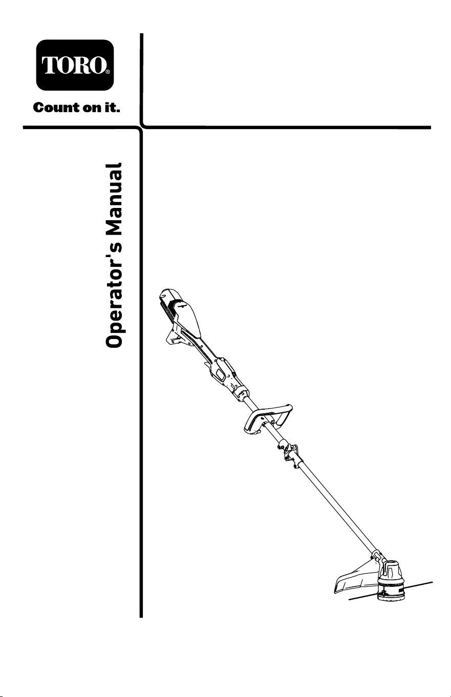
Whenever you need service, genuine the manufacturer parts, or additional
information, contact an Authorized Service Dealer or the manufacturer
Customer Service and have the model and serial numbers of your product
ready . Figure 1 identies the location of the model and serial numbers on
the product. W rite the numbers in the space provided.
Important: W ith your mobile device, you can scan the QR code on
the serial number decal (if equipped) to access warranty , parts, and
other product information.
g507019
Figure 1
1. Model number , serial number , and QR code location
Model No.
Serial No.
3

Safety-Alert Symbol
The safety-alert symbol ( Figure 2 ) shown in this manual and on the
machine identies important safety messages that you must follow to
prevent accidents.
g000502
Figure 2
Safety-alert symbol
The safety-alert symbol appears above information that alerts you to
unsafe actions or situations and is followed by the word DANGER ,
W ARNING , or CAUTION .
DANGER indicates an imminently hazardous situation which, if not
avoided, will result in death or serious injury .
W ARNING indicates a potentially hazardous situation which, if not
avoided, could result in death or serious injury .
CAUTION indicates a potentially hazardous situation which, if not avoided,
may result in minor or moderate injury .
This manual uses two other words to highlight information. Important calls
attention to special mechanical information and Note emphasizes general
information worthy of special attention.
4

Safety
W ARNING
Read all safety warnings, instructions, illustrations and
specications provided with this machine.
Failure to follow all instructions listed below may result in
electric shock, re and/or serious injury .
Save all warnings and instructions for future reference.
The term “machine” in all the warnings refers to your mains-operated
(corded) machine or battery-operated (cordless) machine.
I. W ork area safety
1. Keep work area clean and well lit. Cluttered or dark areas invite
accidents.
2. Do not operate machines in explosive atmospheres, such as in
the presence of ammable liquids, gases, or dust. Machines
create sparks which may ignite the dust or fumes.
3. Keep children and bystanders away while operating a machine.
Distractions can cause you to lose control.
II. Electrical safety
1. Machine plugs must match the outlet. Never modify the plug in
any way . Do not use any adapter plugs with earthed (grounded)
machines. Unmodied plugs and matching outlets will reduce risk of
electric shock.
2. A void body contact with earthed or grounded surfaces, such as
pipes, radiators, ranges and refrigerators. There is an increased
risk of electric shock if your body is earthed or grounded.
3. Do not expose machines to rain or wet conditions. W ater
entering a machine will increase the risk of electric shock.
4. Do not abuse the cord. Never use the cord for carrying, pulling
or unplugging the machine. Keep cord away from heat, oil,
sharp edges or moving parts. Damaged or entangled cords
increase the risk of electric shock.
5

5. When operating a machine outdoors, use an extension cord
suitable for outdoor use. Use of a cord suitable for outdoor use
reduces the risk of electric shock.
6. If operating a machine in a damp location is unavoidable, use a
residual current device (RCD) protected supply . Use of an RCD
reduces the risk of electric shock.
III. Personal safety
1. Stay alert, watch what you are doing and use common sense
when operating a machine. Do not use a machine while you are
tired or under the inuence of drugs, alcohol, or medication.
A moment of inattention while operating machines may result in
serious personal injury .
2. Use personal protective equipment. Always wear eye
protection. Protective equipment such as a dust mask, non-skid
safety shoes, hard hat, or hearing protection used for appropriate
conditions reduces personal injuries.
3. Prevent unintentional starting. Ensure the switch is in the
O FF -position before connecting to power source and/or battery
pack, picking up or carrying the tool. Carrying machines with your
nger on the switch or energizing machines that have the switch
on invites accidents.
4. Remove any adjusting key or wrench before turning the
machine on. A wrench or a key left attached to a rotating part of the
machine may result in personal injury .
5. Do not overreach. Keep proper footing and balance at all times.
This enables better control of the machine in unexpected situations.
6. Dress properly . Do not wear loose clothing or jewelry . Keep
your hair and clothing away from moving parts. Loose clothes,
jewelry , or long hair can be caught in moving parts.
7. If devices are provided for the connection of dust extraction and
collection facilities, ensure these are connected and properly
used. Use of dust collection can reduce dust-related hazards.
8. Do not let familiarity gained from frequent use of tools allow
you to become complacent and ignore tool safety principles. A
careless action can cause severe injury within a fraction of a second.
6

IV . Machine use and care
1. Do not force the machine. Use the correct machine for your
application. The correct machine will do the job better and safer at
the rate for which it was designed.
2. Do not use the machine if the switch does not turn it on and off.
Any machine that cannot be controlled with the switch is dangerous
and must be repaired.
3. Disconnect the plug from the power source and/or remove the
battery pack, if detachable, from the machine before making
any adjustments, changing accessories, or storing machines.
Such preventive safety measures reduce the risk of starting the
machine accidentally .
4. Store idle machines out of the reach of children and do not
allow persons unfamiliar with the machine or these instructions
to operate the machine. Machines are dangerous in the hands
of untrained users.
5. Maintain machines and accessories. Check for misalignment
or binding of moving parts, breakage of parts, and any other
condition that may affect the machine’ s operation. If damaged,
have the machine repaired before use. Many accidents are
caused by poorly maintained machines.
6. Keep cutting tools sharp and clean. Properly maintained cutting
tools with sharp cutting edges are less likely to bind and are easier
to control.
7. Use the machine, accessories, and tool bits etc. in accordance
with these instructions, taking into account the working
conditions and the work to be performed. Use of the machine for
operations different from those intended could result in a hazardous
situation.
8. Keep handles and grasping surfaces dry , clean and free from oil
and grease. Slippery handles and grasping surfaces do not allow for
safe handling and control of the tool in unexpected situations.
7

V . Battery tool use and care
1. Recharge only with the charger specied by the manufacturer .
A charger that is suitable for one type of battery pack may create a
risk of re when used with another battery pack.
2. Use machines only with specically designated battery packs.
Use of any other battery packs may create a risk of injury and re.
3. When battery pack is not in use, keep it away from other metal
objects, like paper clips, coins, keys, nails, screws or other
small metal objects, that can make a connection from one
terminal to another . Shorting the battery terminals together may
cause burns or a re.
4. Under abusive conditions, liquid may be ejected from the
battery; avoid contact. If contact accidentally occurs, ush with
water . If liquid contacts eyes, additionally seek medical help.
Liquid ejected from the battery may cause irritation or burns.
5. Do not use a battery pack or tool that is damaged or modied.
Damaged or modied batteries may exhibit unpredictable behavior
resulting in re, explosion or risk of injury .
6. Do not expose a battery pack or tool to re or excessive
temperature. Exposure to re or temperature above 130 °C (265
°F) may cause explosion.
7. Follow all charging instructions and do not charge the battery
pack or tool outside the temperature range specied in the
instructions. Charging improperly or at temperatures outside the
specied range may damage the battery and increase the risk of re.
VI. Service
1. Have your machine serviced by a qualied repair person using
only identical replacement parts. This will ensure that the safety of
the machine is maintained.
2. Never service damaged battery packs. Service of battery packs
should only be performed by the manufacturer or authorized service
providers.
8

VII. String T rimmer safety
1. Do not use the machine in bad weather conditions, especially
when there is a risk of lightning. This decreases the risk of being
struck by lightning.
2. Thoroughly inspect the area for wildlife where the machine is to
be used. W ildlife may be injured by the machine during operation.
3. Thoroughly inspect the area where the machine is to be used
and remove all stones, sticks, wires, bones, and other foreign
objects. Thrown objects can cause personal injury .
4. Before using the machine, always visually inspect to see that
the cutter or blade and the cutter or blade assembly are not
damaged. Damaged parts increase the risk of injury .
5. Follow instructions for changing accessories. Improperly
tightened blade securing nuts or bolts may either damage the blade
or result in it becoming detached.
6. The rated rotational speed of the blade must be at least equal to
the maximum rotational speed marked on the machine. Blades
running faster than their rated rotational speed can break and y
apart.
7. W ear eye, ear , head and hand protection. Adequate protective
equipment will reduce personal injury by ying debris or accidental
contact with the cutting line or blade.
8. While operating the machine, always wear non-slip and
protective footwear . Do not operate the machine when barefoot
or wearing open sandals. This reduces the chance of injury to the
feet from contact with the moving cutters or lines.
9. While operating the machine, always wear safety footwear .
Do not operate the machine when barefoot or wearing open
sandals. This reduces the chance of injury to the feet from contact
with a moving cutter , line or blade.
10. While operating the machine, always wear long trousers.
Exposed skin increases the likelihood of injury from thrown objects.
1 1. Keep bystanders away while operating the machine. Thrown
debris can result in serious personal injury .
12. Always use two hands when operating the machine. Holding the
machine with both hands will avoid loss of control.
13. Hold the machine by the insulated gripping surfaces only ,
because the cutting line or blade may contact hidden wiring.
Cutting line or blades contacting a "live" wire may make exposed
9

metal parts of the machine "live" and could give the operator an
electric shock.
14. Always keep proper footing and operate the machine only when
standing on the ground. Slippery or unstable surfaces may cause
a loss of balance or control of the machine.
15. Do not operate the machine on excessively steep slopes. This
reduces the risk of loss of control, slipping and falling which may
result in personal injury .
16. When working on slopes, always be sure of your footing,
always work across the face of slopes, never up or down and
exercise extreme caution when changing direction. This reduces
the risk of loss of control, slipping and falling which may result in
personal injury .
17. Keep all parts of the body away from the cutter , line or blade
when the machine is operating. Before you start the machine,
make sure the cutter , line or blade is not contacting anything.
A moment of inattention while operating the machine may result in
injury to yourself or others.
18. Do not operate the machine above waist height. This helps
prevent unintended cutter or blade contact and enables better control
of the machine in unexpected situations.
19. When cutting brush or saplings that are under tension, be
alert for spring back. When the tension in the wood bers is
released, the brush or sapling may strike the operator and/or throw
the machine out of control.
20. Use extreme caution when cutting brush and saplings. The
slender material may catch the blade and be whipped toward you or
pull you off balance.
21. Maintain control of the machine and do not touch cutters, lines
or blades and other hazardous moving parts while they are still
in motion. This reduces the risk of injury from moving parts.
22. Carry the machine with the machine switched off and away from
your body . Proper handling of the machine will reduce the likelihood
of accidental contact with a moving trimmer cutter , line or blade.
23. Only use replacement cutters, lines, cutting heads and blades
specied by the manufacturer . Incorrect replacement parts may
increase the risk of breakage and injury .
SA VE THESE
INSTRUCTIONS
10
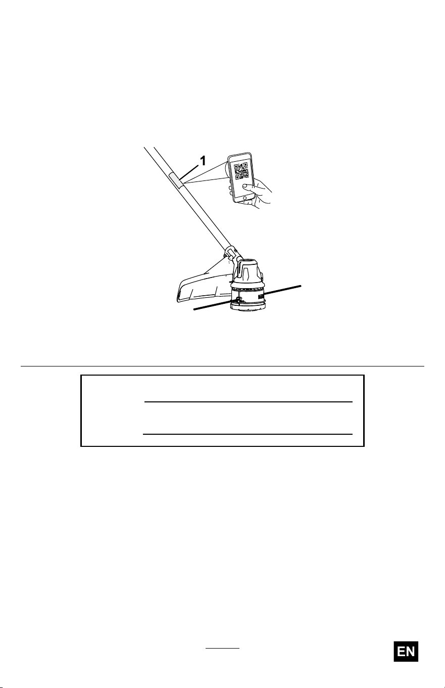
Safety and Instructional Decals
Safety decals and instructions are easily visible to the
operator and are located near any area of potential
danger . Replace any decal that is damaged or missing.
decal161-7083
161-7083
1. W arning—read the Operator ’ s
Manual ; wear eye protection; wear
hearing protection; never t metal
cutting parts; stay away from moving
parts; keep all guards in place; do not
operate in wet conditions.
1 1
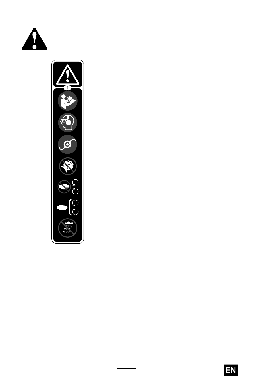
decal161-7077b
161-7077
1. W arning—remove the battery pack
before performing maintenance.
2. Thrown object hazard—keep
bystanders at least 15 m (50 ft) away .
decal161-7078b
161-7078
1. W arning—remove the battery pack
before performing maintenance.
2. Thrown object hazard—keep
bystanders at least 15 m (50 ft) away .
decal161-7051b
161-7051
12

decal161-3788
161-3788
decal161-3775
161-3775
1. The battery pack is charging. 3. The battery pack is over or under the
appropriate temperature range.
2. The battery pack is fully charged. 4. Battery pack charging fault
decal161-3774
161-3774
decal161-3764
161-3764
1. Battery charge status
13
decal145-8287
145-8287
1. Read the
Operator ’ s
Manual .
5. Keep away
from open re
or ames
2. Call2Recycle
®
battery
recycling
program
6. Do not expose
to rain
3. Recycle the
battery
7. Electrical shock
hazard
4. Do not dispose
improperly
14

Setup
Loose Parts
Use the chart below to verify that all parts have been shipped.
Procedure Description
Qty .
Use
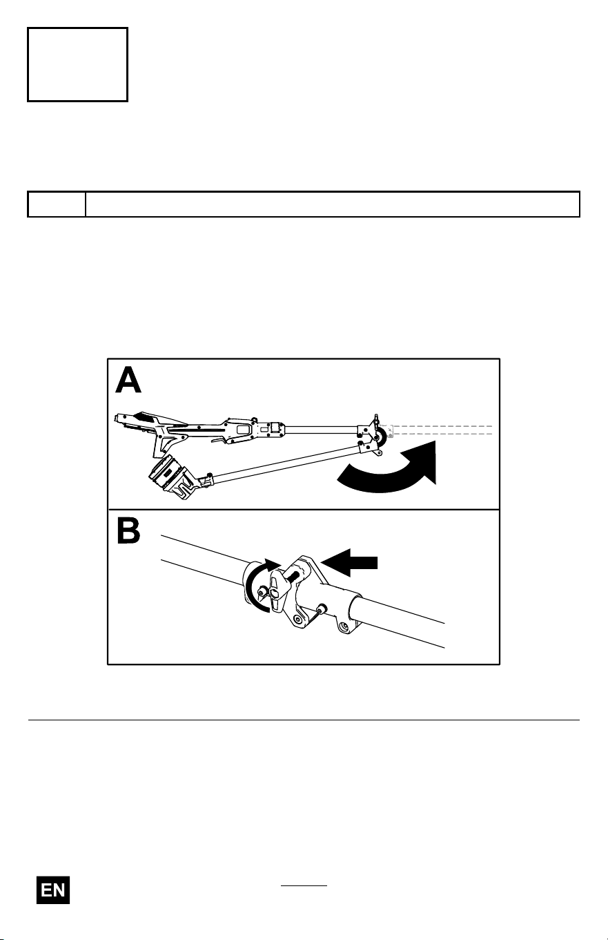
1
Connector knob
1
Unfold the shaft.
2
Auxiliary handle assembly 1
Install the auxiliary
handle.
3
Guard
1 Install the guard.
Important: The battery pack is not fully charged when you purchase
it. Before using the tool for the rst time, refer to Charging the
Battery Pack ( page 27 ) .
15
2
Installing the Auxiliary Handle
Parts needed for this procedure:
1 Auxiliary handle assembly
Procedure
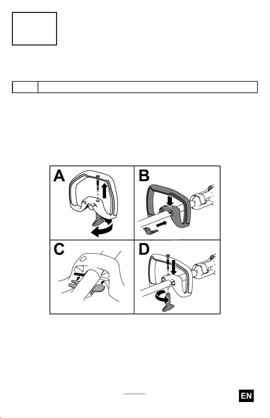
1. Separate the auxiliary handle from the handle bracket by unscrewing
the handle-lock knob and removing the bolt (A of Figure 4 ).
Important: The bolt may be wedged into the plastic of the
handle; lightly tap the bottom of the bolt until it is free from
the handle.
g507673
Figure 4
2. Align the handle bracket with the auxiliary handle (B of Figure 4 ).
3. Slide the handle bracket into the slot on the auxiliary handle (C of
Figure 4 ).
4. Secure the lower handle bracket to the auxiliary handle with the
handle-lock knob and the previously removed bolt (D of Figure 4 ).
17
3
Installing the Guard
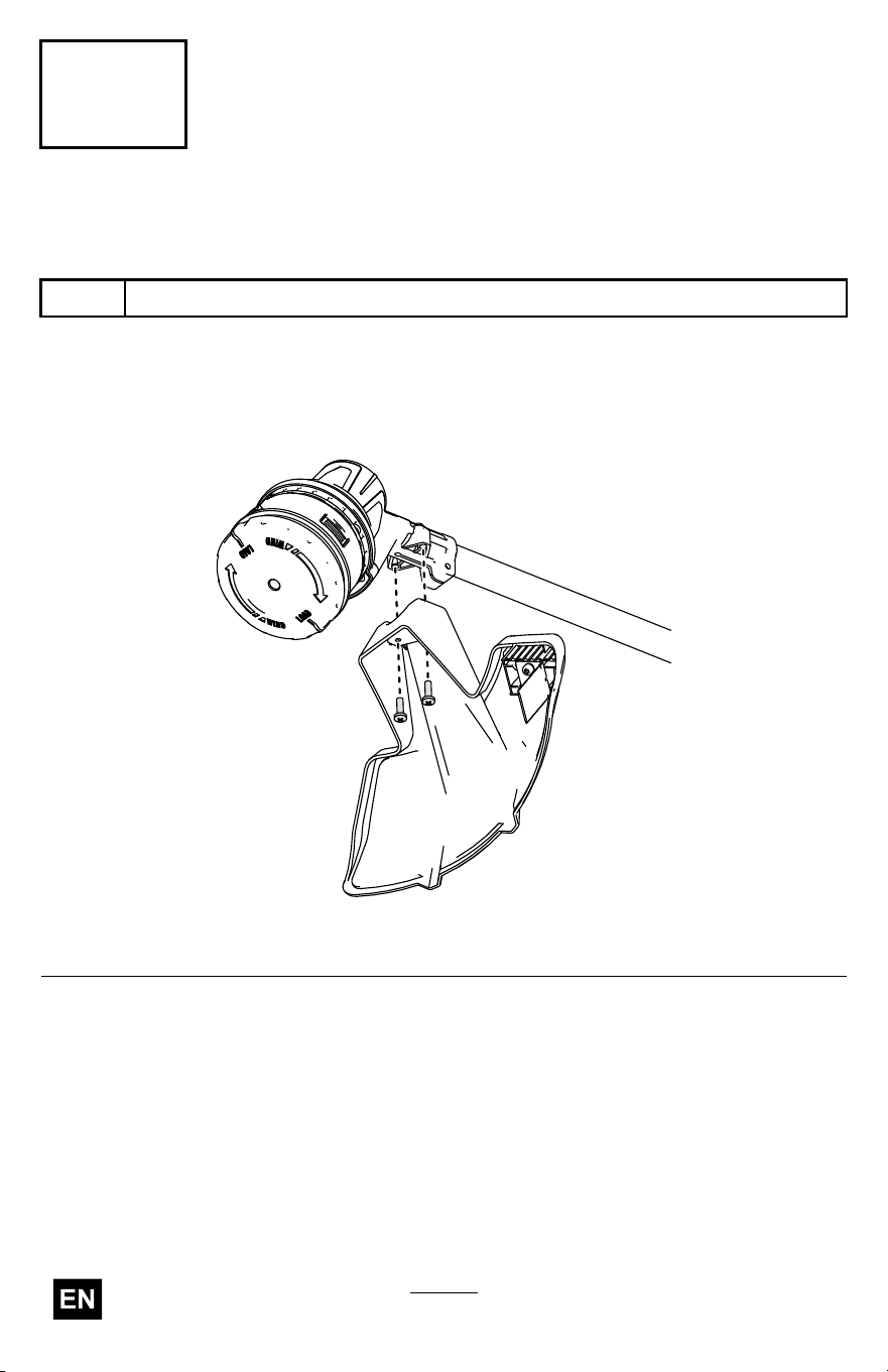
Parts needed for this procedure:
1
Guard
Procedure
Secure the guard onto the base of the trimmer with the 2 screws.
g507687
Figure 5
18
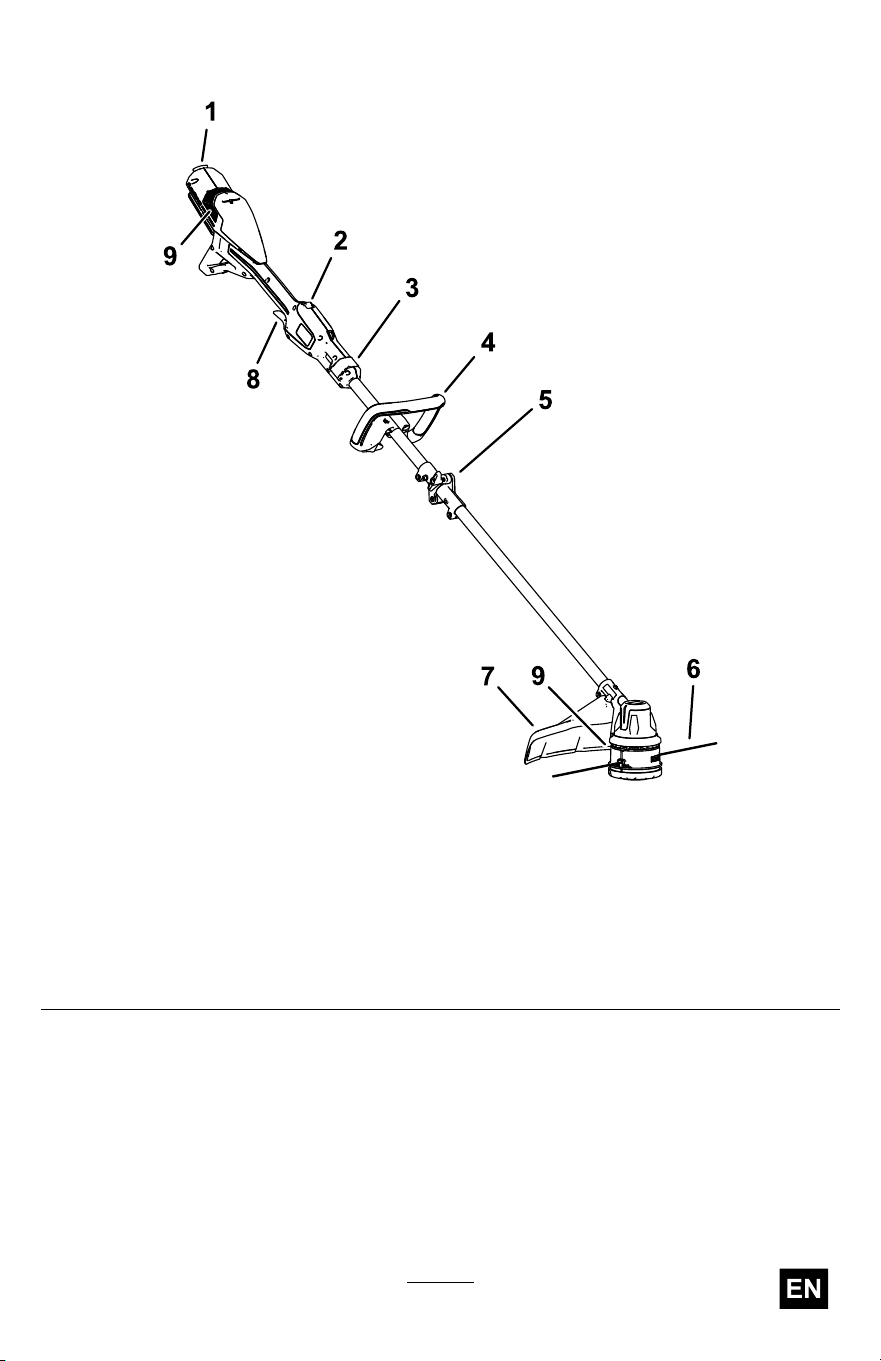
Product Overview
g507020
Figure 6
1. Battery latch
6. Cutting line
2. Lockout switch
7. Guard
3. T elescoping latch 8. Run trigger
4. Auxiliary handle 9. T rimmer vents
5. Mid-shaft coupler
19

Specications
Model
51838/T
Rated V oltage
60V DC maximum, 54 VDC nominal usage
Charger T ype
Flex-Force 60V lithium-ion chargers
Battery T ype
Flex-Force 60V lithum-ion batteries*
If you are using this machine with a battery pack that is 8.0 Ah or greater ,
you must install quick-release harness Model 139-5334 (not included).
Appropriate T emperature Ranges
Charge/store the battery pack at 5°C (41°F) to 40°C (104°F)*
Use the battery pack at
-30°C (-22°F) to 49°C (120°F)
Use the trimmer at
0°C (32°F) to 49°C (120°F)
Store the trimmer at 0°C (32°F) to 49°C (120°F)*
*Charging time will increase if you do not charge the battery within this
range.
Store the tool, battery pack, and battery charger in an enclosed clean,
dry area.
Attachments/Accessories
A selection of T oro approved attachments and accessories is available for
use with the machine to enhance and expand its capabilities. Contact
your Authorized Service Dealer or authorized T oro distributor or go to
www .T oro.com for a list of all approved attachments and accessories.
T o ensure optimum performance and continued safety certication of the
machine, use only genuine T oro replacement parts and accessories.
Replacement parts and accessories made by other manufacturers could
be dangerous.
20
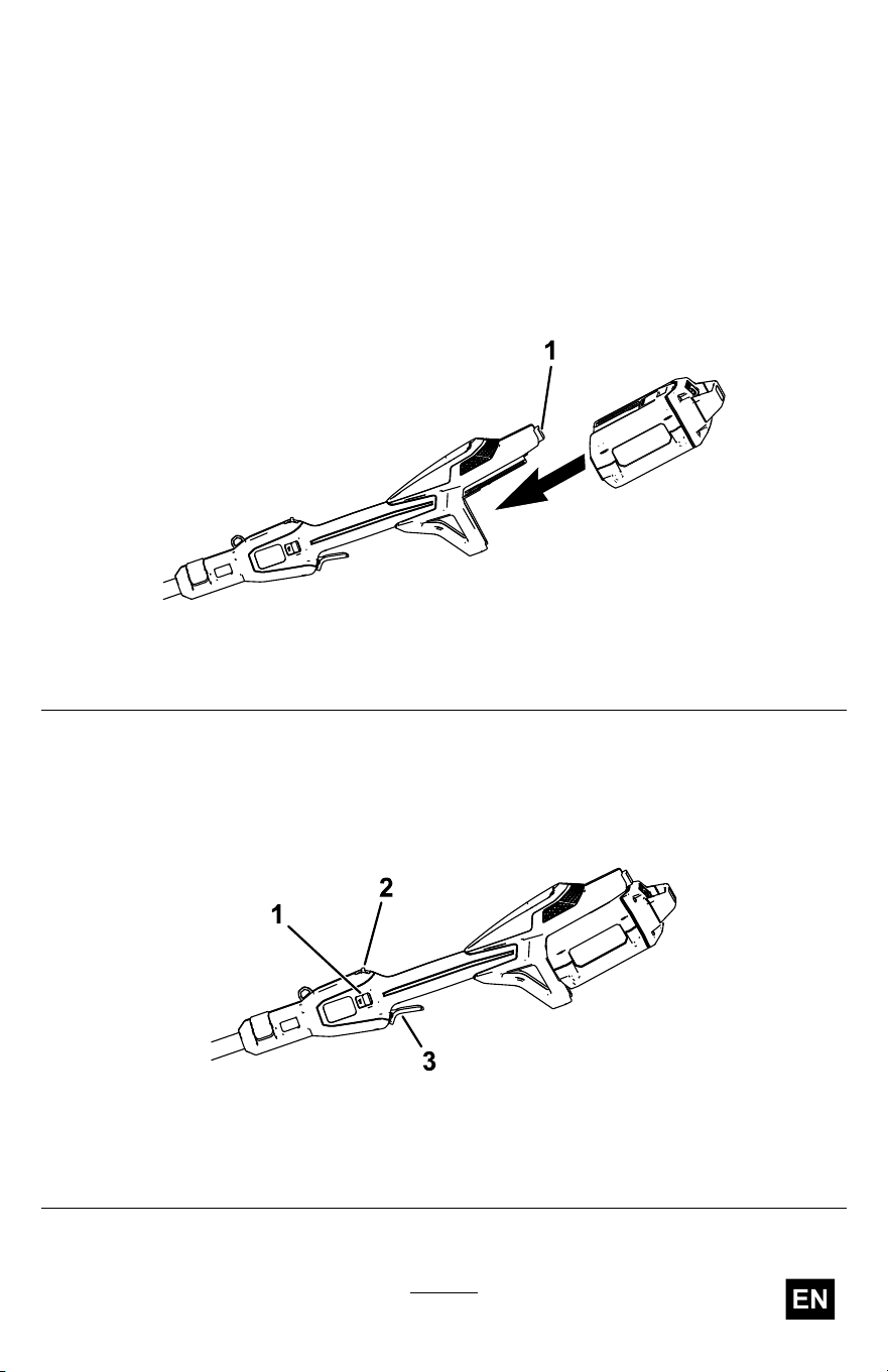
Operation
Starting the T rimmer
1. Ensure that the vents on the trimmer are clear of any dust and debris.
2. Align the cavity in the battery pack with the tongue on the power
head ( Figure 7 ).
3. Push the battery pack into the power head until the battery locks
into the latch ( Figure 7 ).
g507688
Figure 7
1. Battery latch
4. T o start the trimmer , pull back the lockout switch, then squeeze the
variable-speed trigger ( Figure 8 ).
Note: Slide the speed range switch to change the speed of the
trimmer .
g507689
Figure 8
1. Speed range switch
3. V ariable-speed trigger
2. Lockout switch
21
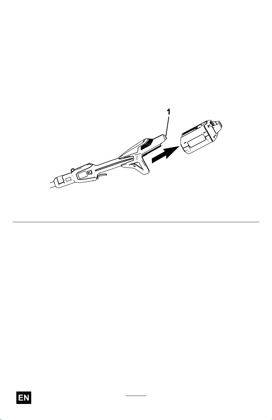
Shutting Off the T rimmer
T o shut of f the trimmer , release the trigger and the lockout switch.
Whenever you are not using the trimmer or are transporting the trimmer to
or from the work area, remove the battery pack.
Removing the Battery Pack from the T rimmer
Press the battery latch to release the battery pack and slide the battery
pack out of the machine ( Figure 9 ).
g507691
Figure 9
1. Battery latch
22
Adjusting the Auxiliary Handle Position
1. Loosen the handle-lock knob on the bottom of the auxiliary handle.
2. Adjust the position of the auxiliary handle on the shaft until the
trimmer can held in a neutral, comfortable position while operating.
3. T ighten the handle-lock knob to secure auxiliary handle in place.
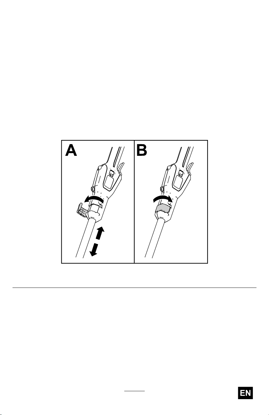
Adjusting the Shaft Length
1. Open the telescoping latch at the front of the handle.
2. Extend or retract the shaft until the trimmer can held in a neutral,
comfortable position while operating.
3. Close the telescoping latch to secure the shaft.
g507705
Figure 10
23
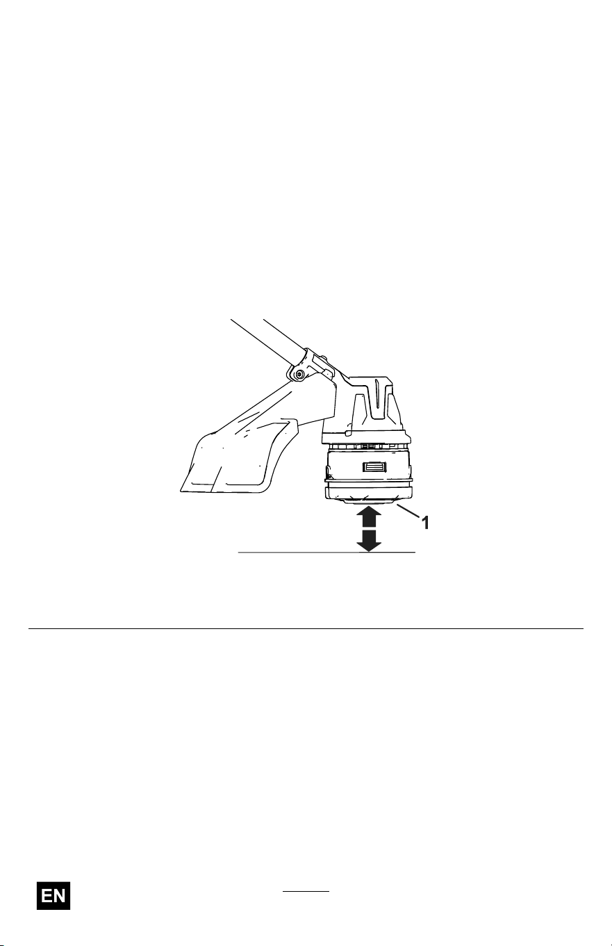
Advancing the Line Using the Bump Feed
1. Run the tool at full throttle.
2. T ap the bump head on the ground to advance the line. The line
advances each time the bump head is tapped.
Important: Do not hold the bump head on the ground while
running the trimmer .
Note: The line trimming cut-of f blade on the grass deector cuts the
line to the correct length.
Note: If the line is worn too short, you may not be able to advance
the line by tapping it on the ground. If so, release both the trigger
and the lockout switch and refer to Advancing the Line Manually
( page 24 ) .
g507693
Figure 1 1
1. Bump head
Advancing the Line Manually
Remove the battery pack from the trimmer , then push the bump head at
the base of the spool retainer while pulling on the trimmer line to manually
advance the line.
24
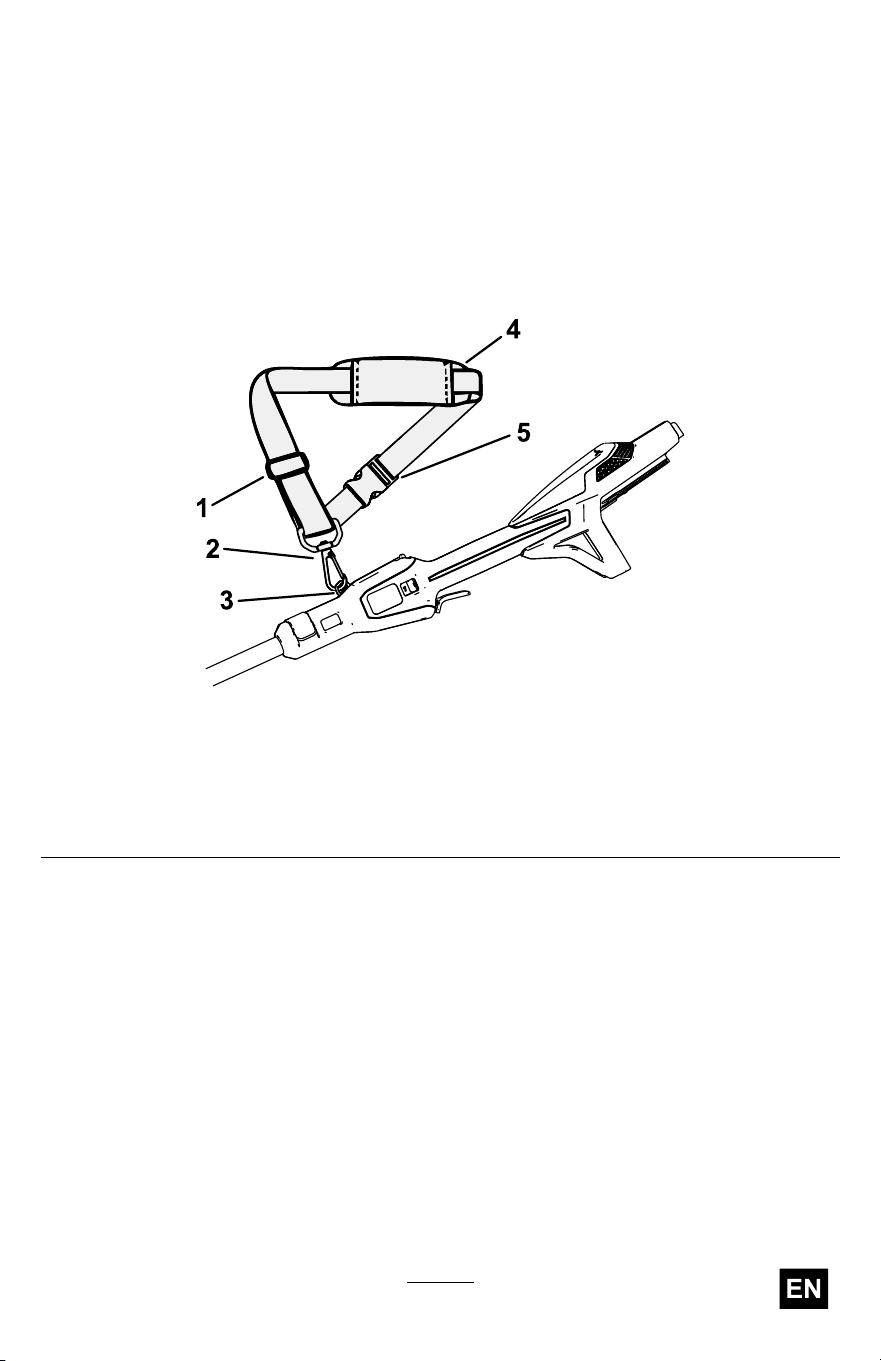
Using the Shoulder Harness
Important: If you are using the string trimmer with a 8.0 Ah or greater
battery pack installed, install a shoulder harness (not included).
Do not use the shoulder harness if you are powering the string
trimmer with the backpack and backpack tether; use only the
backpack harness.
Connect the clip on the shoulder harness to the attachment eye on top
of the handle ( Figure 12 ).
g507529
Figure 12
1. Strap adjuster 4. Shoulder pad
2. Pivot clip
5. Quick-release buckle
3. Attachment eye
The strap length is adjustable; slide the strap adjuster up to decrease the
length of the strap, or down to increase the length of the strap ( Figure 12 ).
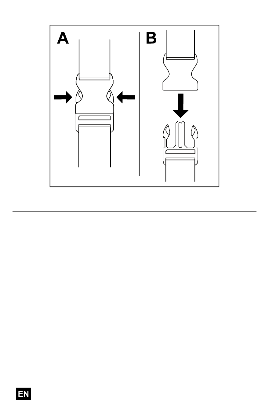
If there you ever need to rapidly remove the harness, disconnect the
quick-release buckle as follows:
1. Press in on the sides of the buckle (A of Figure 13 ).
25
Charging the Battery Pack
Important: The battery pack is not fully charged when you purchase
it. Before using the tool for the rst time, place the battery pack in
the charger and charge it until the LED display indicates the battery
pack is fully charged. Read all safety precautions.
Important: Charge the battery pack only in temperatures that are
within the appropriate range; refer to Specications ( page 20 ) .
Note: At any time, press the battery-charge-indicator button on the
battery pack to display the current charge (LED indicators).
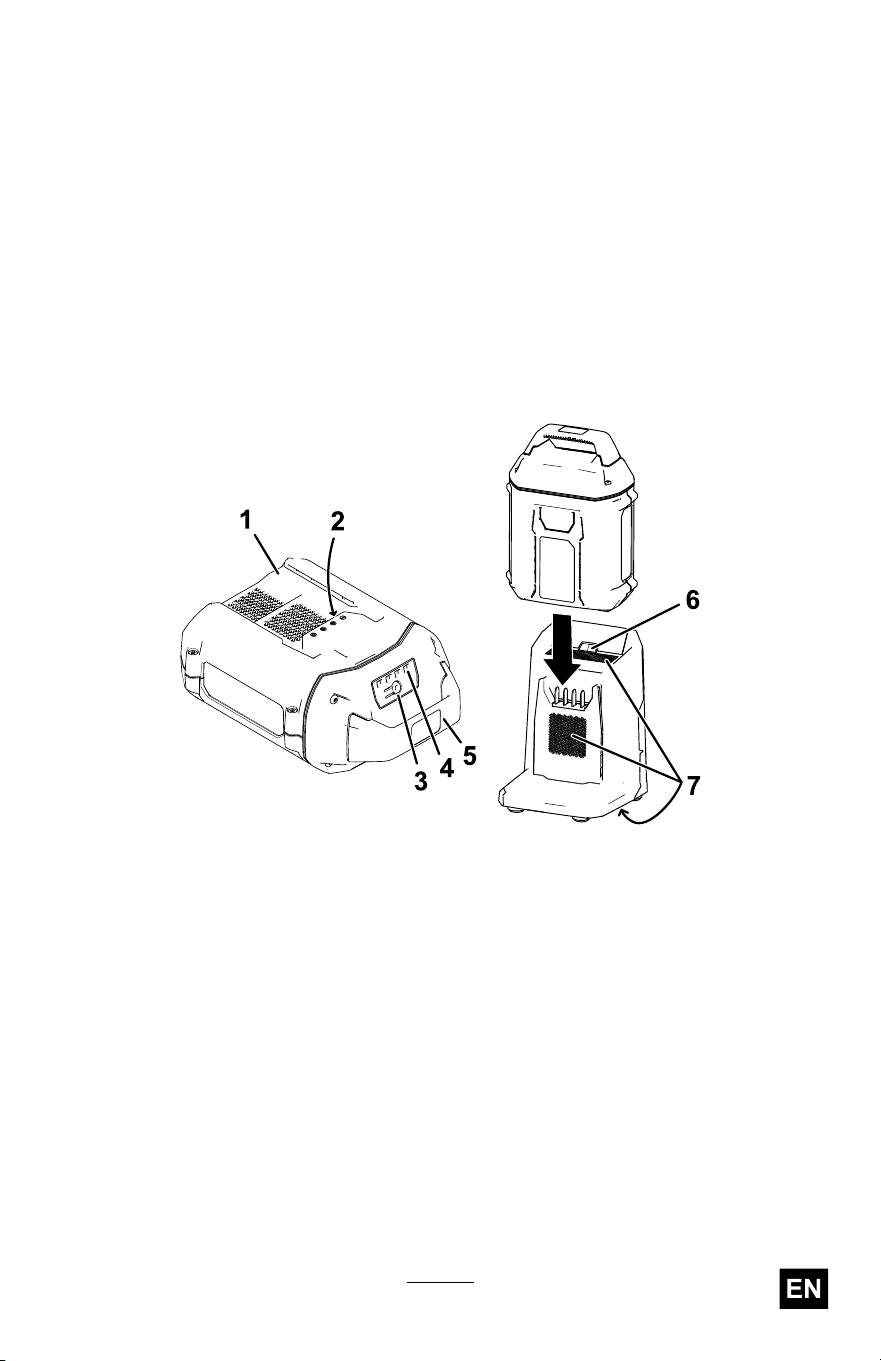
1. Ensure that the vents and charging terminals on the battery pack
and charger are clear of any dust and debris.
g473274
Figure 14
1. Battery-pack cavity 5. Handle
2. Battery-pack terminals
6. Charger LED indicator light
3. Battery-charge-indicator button
7. Charger venting areas
4. LED indicators (current charge)
2. Line up the cavity in the battery pack ( Figure 14 ) with the tongue
on the charger .
3. Slide the battery pack into the charger until it is fully seated ( Figure
14 ).
4. T o remove the battery pack, slide the battery backward out of the
charger .
27

5. Refer to the following table to interpret the LED indicator light on
the battery charger .
Indicator
light
Indicates
Of f
No battery pack inserted
Green
blinking
Battery pack is charging
Green
Battery pack is charged
Red
Battery pack and/or battery charger is over or under the appropriate
temperature range
Red blinking
Battery pack charging fault*
*Refer to T roubleshooting ( page 35 ) for more information.
Important: The battery pack can be left on the charger for short
periods between uses.
If the battery pack will not be used for longer periods, remove the
battery pack from the charger; refer to Storage ( page 34 ) .
28
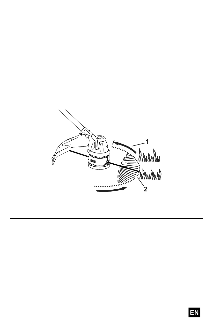
Operating T ips
• Keep the trimmer tilted toward the area being cut; this is the best
cutting area.
• The string trimmer cuts when you move it from right to left. This
prevents the trimmer from throwing debris at you.
• Use the tip of the cutting line to do the cutting; do not force the trimmer
head into uncut grass.
• Wire and picket fences can cause the cutting line to wear rapidly and
even break. Stone and brick walls, curbs, and wood can also cause
the cutting line to wear rapidly .
• A void trees and shrubs. The cutting line can easily damage tree bark,
wood moldings, siding, and fence posts.
g507692
Figure 15
1. Direction of rotation 2. Cutting line path
29

Maintenance
After each use of the trimmer , complete the following:
1. Remove the battery pack from the trimmer .
2. Wipe the trimmer clean with a damp cloth. Do not hose the trimmer
down or submerge it in water .
CAUTION
The line cutoff blade on the deector is sharp and can cut
you.
Do not use your hands to clean the deector shield and
blade.
3. Wipe or scrape clean the cutting head area any time there is an
accumulation of debris.
4. Check and tighten all fasteners. If any part is damaged or lost, repair
or replace it.
5. Brush debris away from air intake vents on the power head and the
exhaust on the motor housing to prevent the motor from overheating.
Replacing the Cutting Line
Use only 2.0 mm (0.080 inch) diameter monolament cutting line or 2.4
mm (0.095 inch) diameter twisted monolament cutting line from T oro.
1. Remove the battery pack from the trimmer .
2. Remove any existing line on the spool by repetitively pressing the
bump head while pulling the line out equally from both sides of the
bump head.
3. Cut a piece of line that is no longer than 7.3 m (24 ft).
Important: Do not overload the spool.
Important: Do not use any other gauge or type of line, as this
could damage the trimmer .
4. Press and turn the bump head in the direction shown by the arrows
(clockwise) on the bottom of the bump head until the marks on the
side of the bump head align with the marks beneath the eyelets
( Figure 16 ).
30
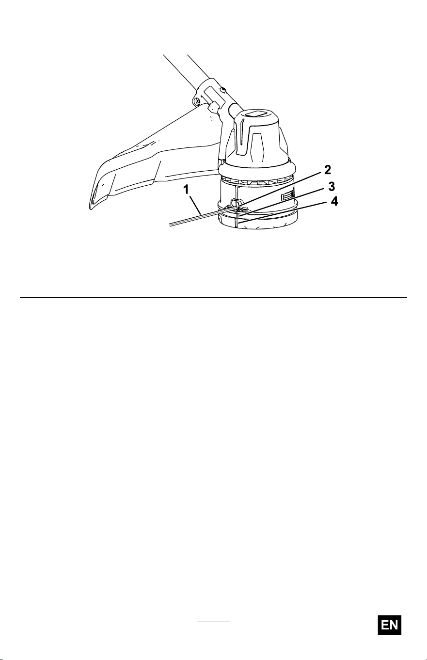
5. Insert 1 end of the line straight into the eyelet and push the line
through until it comes out of the eyelet on the other side.
g507694
Figure 16
1. Cutting line
3. Eyelet alignment mark
2. Eyelet 4. Bump head alignment mark
Important: Do not disassemble the trimmer head.
6. Pull the line through the eyelets until there is an equal length of line
on each side of the trimmer head.
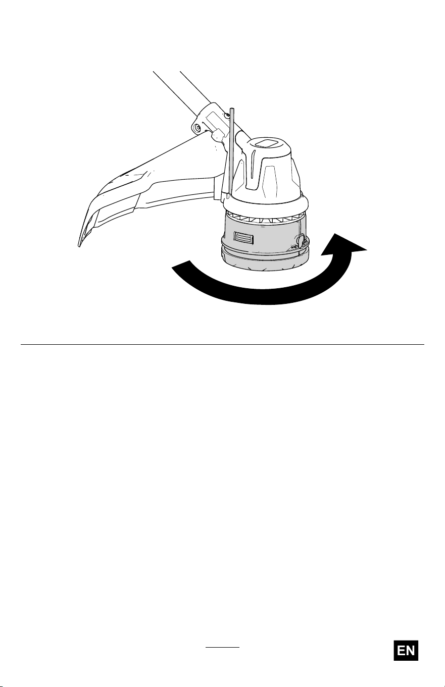
7. Hold the string trimmer in place with one hand. With your other
hand, turn the bottom of the trimmer head in the direction shown by
the arrows (clockwise) on the bottom of the bump head to wind the
line; leave about 152 mm (6 inches) extending beyond the eyelet
on each side.
31
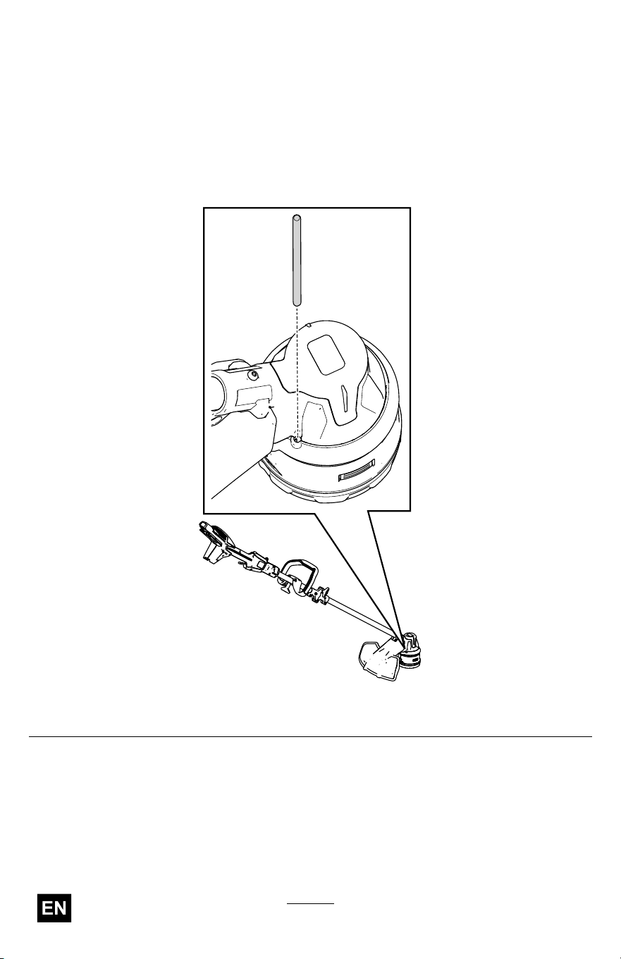
Replacing the T rimmer Head
1. Remove the battery pack from the trimmer .
2. Insert a small-diameter tool (such as a screwdriver) through the
motor housing and into the groove in the fan to secure the trimmer
head so it does not freely rotate ( Figure 17 ).
Note: With the tool inserted in the hole, rotate the trimmer head until
you feel the rod fall into the groove.
g512077
Figure 17
32

Storage
Important: Store the machine, battery pack, and charger only
in temperatures that are within the appropriate range; refer to
Specications ( page 20 ) .
Important: If you are storing the machine for a year or longer ,
remove the battery pack from the machine and charge the battery
pack until 1 or 2 LED indicators turn green on the battery . Do not
store a fully charged or fully depleted battery . When you are ready to
use the machine again, charge the battery pack until the left indicator
light turns green on the charger or all 4 LED indicators turn green
on the battery .
• Disconnect the machine from the power supply (i.e., remove the
battery pack) and check for damage after use.
• Clean all foreign material from the machine.
• Do not store the machine or charger with the battery pack installed.
• When not in use, store the machine, battery pack, and battery charger
out of the reach of children.
• Keep the machine, battery pack, and battery charger away from
corrosive agents such as garden chemicals and de-icing salts.
• T o reduce the risk of serious personal injury , do not store the battery
pack outside or in vehicles.
• Store the machine, battery pack, and battery charger in an enclosed
clean, dry area.
• When the machine is folded for storage, do not hang it from the
electrical wire harness.
34

T roubleshooting
Perform only the steps described in these instructions. All further
inspection, maintenance, and repair work must be performed by an
authorized service center or a similarly qualied specialist if you cannot
solve the problem yourself.
Always remove the battery from the tool when troubleshooting, inspecting,
maintaining, or cleaning the tool.
Problem
Possible Cause Corrective Action
1. The battery is not fully
installed in the tool.
1. Remove and then
replace the battery into
the tool, making sure
that it is fully installed
and latched.
2. The battery pack is not
charged.
2. Remove the battery
pack from the tool and
charge it.
3. The battery pack is over
or under the appropriate
temperature range.
3. Move the battery pack
to a place where it is
dry and the temperature
is between 5°C (41°F)
and 40°C (104°F).
4. There is moisture on
the leads of the battery
pack.
4. Allow the battery pack
to dry or wipe it dry .
5. The battery pack is
damaged.
5. Replace the battery
pack.
The tool does not run or
does not run continuously .
6. There is another
electrical problem with
the tool.
6. Contact an Authorized
Service Dealer .
1. The battery pack charge
capacity is too low .
1. Remove the battery
pack from the tool and
fully charge the battery
pack.
The tool does not reach full
power or the motor housing
is getting hot.
2. The air vents are
blocked.
2. Clean the air vents.
35

Problem
Possible Cause Corrective Action
1. There is debris under
the grass shield or in
the bump head housing
on the trimmer .
1. Clean any debris from
under the grass shield
or in the bump head
housing.
The tool is producing
excessive vibration or
noise.
2. The spool is not
properly wound.
2. Advance the line using
the bump head and/or
remove the line on the
spool and wind the
spool again.
1. The trimmer is out of
line.
1. Add more line to the
bump head.
2. The line is tangled in the
bump head housing.
2. Remove the bump head
cover and untangle the
line.
The bump head does not
advance the line.
3. There is debris under
the grass shield or in
the bump head housing
on the trimmer .
3. Clean any debris from
under the grass shield
or in the bump head
housing.
1. The battery pack is over
or under the appropriate
temperature range.
1. Move the battery pack
to a place where it is
dry and the temperature
is between 5°C (41°F)
and 40°C (104°F).
The battery pack loses
charge quickly .
2. The trimmer is
overloaded.
2. T rim at a slower pace.
1. The battery charger
is over or under
the appropriate
temperature range.
1. Unplug the battery
charger and move it to
a place where it is dry
and the temperature
is between 5°C (41°F)
and 40°C (104°F).
The battery charger is not
working.
2. The outlet that the
battery charger is
plugged into does not
have power .
2. Contact your licensed
electrician to repair the
outlet.
The LED indicator light on
the battery charger is red.
1. The battery charger
and/or battery pack
is over or under
the appropriate
temperature range.
1. Unplug the battery
charger and move the
battery charger and
battery pack to a place
where it is dry and the
temperature is between
5°C (41°F) and 40°C
(104°F).
36

Problem
Possible Cause Corrective Action
1. There is an error in
the communication
between the battery
pack and the charger .
1. Remove the battery
pack from the battery
charger , unplug the
battery charger from
the outlet, and wait
10 seconds. Plug the
battery charger into the
outlet again and place
the battery pack on the
battery charger . If the
LED indicator light on
the battery charger is
still blinking red, repeat
this procedure again.
If the LED indicator
light on the battery
charger is still blinking
red after 2 attempts,
properly dispose of the
battery pack at a battery
recycling facility .
The LED indicator light
on the battery charger is
blinking red.
2. The battery pack is
weak.
2. Properly dispose of the
battery pack at a battery
recycling facility .
37

Notes:

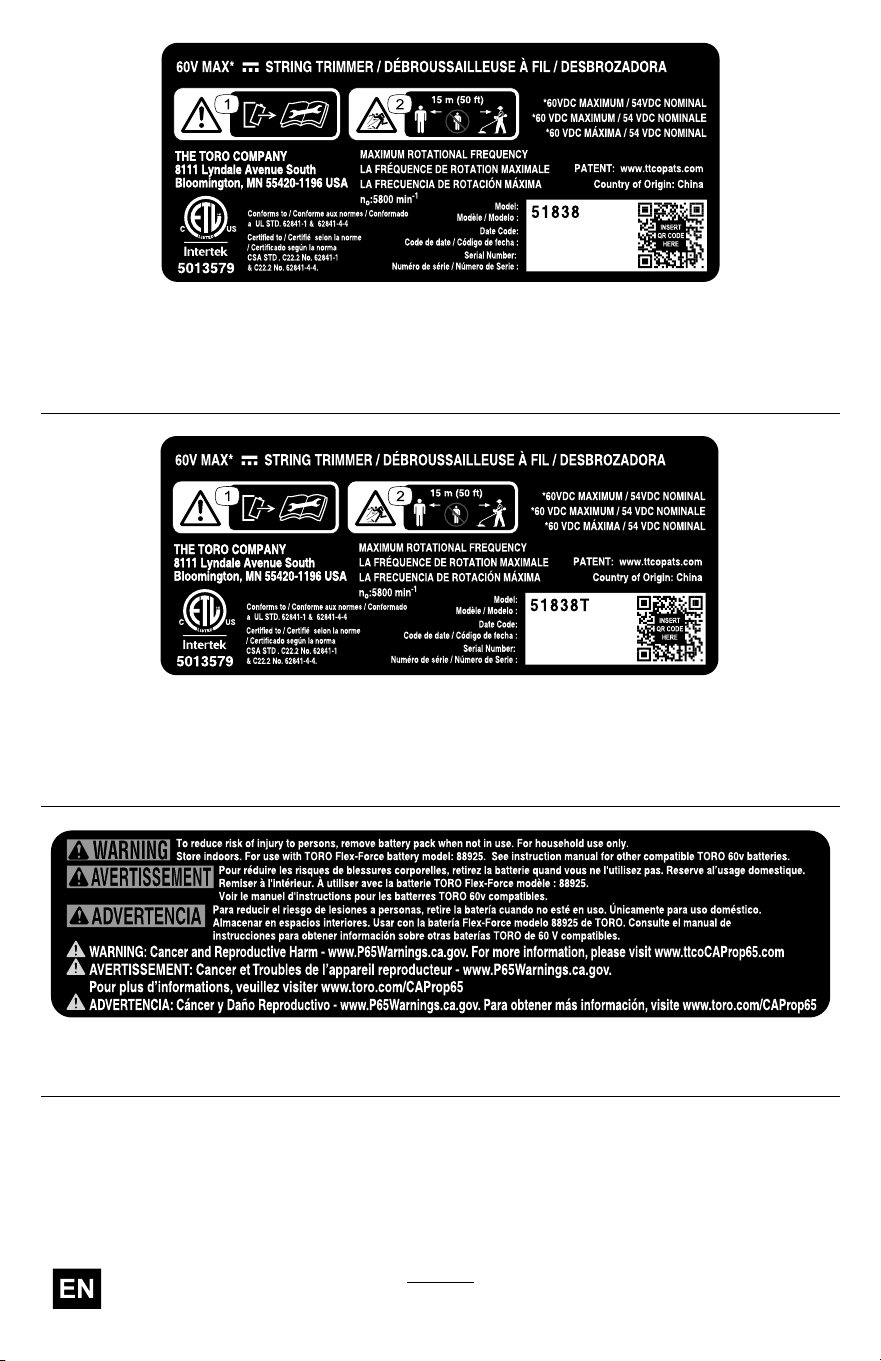
California Proposition 65 W arning Information
What is this warning?
Y ou may see a product for sale that has a warning label like the following:
W ARNING: Cancer and Reproductive
Harm—www .p65W arnings.ca.gov .
What is Prop 65?
Prop 65 applies to any company operating in California, selling products in California, or manufacturing products
that may be sold in or brought into California. It mandates that the Governor of California maintain and publish a
list of chemicals known to cause cancer , birth defects, and/or other reproductive harm. The list, which is updated
annually , includes hundreds of chemicals found in many everyday items. The purpose of Prop 65 is to inform the
public about exposure to these chemicals.
Prop 65 does not ban the sale of products containing these chemicals but instead requires warnings on any product,
product packaging, or literature with the product. Moreover , a Prop 65 warning does not mean that a product is in
violation of any product safety standards or requirements. In fact, the California government has claried that
a Prop 65 warning “is not the same as a regulatory decision that a product is ‘safe’ or ‘unsafe.’” Many of these
chemicals have been used in everyday products for years without documented harm. For more information, go
to https://oag.ca.gov/prop65/faqs-view-all .
A Prop 65 warning means that a company has either (1) evaluated the exposure and has concluded that it exceeds
the “no signicant risk level”; or (2) has chosen to provide a warning based on its understanding about the presence
of a listed chemical without attempting to evaluate the exposure.
Does this law apply everywhere?
Prop 65 warnings are required under California law only . These warnings are seen throughout California in a wide
range of settings, including but not limited to restaurants, grocery stores, hotels, schools, and hospitals, and on a
wide variety of products. Additionally , some online and mail order retailers provide Prop 65 warnings on their
websites or in catalogs.
How do the California warnings compare to federal limits?
Prop 65 standards are often more stringent than federal and international standards. There are various substances
that require a Prop 65 warning at levels that are far lower than federal action limits. For example, the Prop 65
standard for warnings for lead is 0.5 μg/day , which is well below the federal and international standards.
Why don’t all similar products carry the warning?
• Products sold in California require Prop 65 labelling while similar products sold elsewhere do not.
• A company involved in a Prop 65 lawsuit reaching a settlement may be required to use Prop 65 warnings for its
products, but other companies making similar products may have no such requirement.
• The enforcement of Prop 65 is inconsistent.
• Companies may elect not to provide warnings because they conclude that they are not required to do so
under Prop 65; a lack of warnings for a product does not mean that the product is free of listed chemicals
at similar levels.
Why does T oro include this warning?
T oro has chosen to provide consumers with as much information as possible so that they can make informed
decisions about the products they buy and use. T oro provides warnings in certain cases based on its knowledge of
the presence of one or more listed chemicals without evaluating the level of exposure, as not all the listed chemicals
provide exposure limit requirements. While the exposure from T oro products may be negligible or well within the “no
signicant risk” range, out of an abundance of caution, T oro has elected to provide the Prop 65 warnings. Moreover , if
T oro does not provide these warnings, it could be sued by the State of California or by private parties seeking to
enforce Prop 65 and subject to substantial penalties.
Rev