
Operator’s Manual
TimeCutter Max or MyRIDE 50in or 54in
Riding Mower
Model—Serial Range
77501—400000000 and Up
77502—400000000 and Up
77515TA—400000000 and Up
77520TA—400000000 and Up
3464-621A
Original Instructions (EN)
*3464-621*A

Disclaimers and Regulatory Information
It is a violation of California Public Resource Code Section 4442 or 4443 to use or operate
the engine on any forest-covered, brush-covered, or grass-covered land unless the engine
is equipped with a spark arrester, as defined in Section 4442, maintained in effective
working order or the engine is constructed, equipped, and maintained for the prevention of
fire.
Gross or Net Torque: The gross or net torque of this engine was laboratory rated by the
engine manufacturer in accordance with the Society of Automotive Engineers (SAE) J1940
or J2723. As configured to meet safety, emission, and operating requirements, the actual
engine torque on this class of mower will be significantly lower. Please refer to the engine
manufacturer’s information included with the machine.
The enclosed engine owner's manual is supplied for information regarding the US
Environmental Protection Agency (EPA) and the California Emission Control Regulation of
emission systems, maintenance, and warranty. Replacements may be ordered through the
engine manufacturer.
WARNING
CALIFORNIA
Proposition 65
The engine exhaust from this product contains chemicals known to the State of California to
cause cancer, birth defects, or other reproductive harm.
Battery posts, terminals, and related accessories contain lead and lead compounds, chemicals
known to the State of California to cause cancer and reproductive harm. Wash hands after
handling.
Use of this product may cause exposure to chemicals known to the State of California to cause
cancer, birth defects, or other reproductive harm.
Table of Contents
Chapter 1: Introduction........................................................................................................................ 1–1
Intended Use ..................................................................................................................................... 1–1
Getting Help....................................................................................................................................... 1–1
Manual Conventions........................................................................................................................ 1–2
Safety Alert Classifications......................................................................................................... 1–2
Chapter 2: Safety.................................................................................................................................. 2–1
General Safety .................................................................................................................................. 2–1
Slope Indicator .................................................................................................................................. 2–2
Safety and Instructional Decals .................................................................................................... 2–3
Chapter 3: Product Overview ............................................................................................................ 3–1
Control Panel..................................................................................................................................... 3–2
Motion-Control Levers..................................................................................................................... 3–3
Park Position ................................................................................................................................. 3–3
MyRide® Suspension Adjustment Lever.................................................................................... 3–4
© 2023—The Toro
®
Company
8111 Lyndale Ave So
Bloomington, MN 55044
Contact us at www.Toro.com
Printed in the USA
All rights reserved

Height-of-Cut Pin.............................................................................................................................. 3–4
Deck-Lift Pedal.................................................................................................................................. 3–4
Specifications .................................................................................................................................... 3–4
Chapter 4: Operation ........................................................................................................................... 4–1
Before Operation .............................................................................................................................. 4–1
Before Operation Safety ............................................................................................................. 4–1
Fuel .................................................................................................................................................. 4–3
Performing Daily Maintenance .................................................................................................. 4–3
Break-In Time ................................................................................................................................ 4–4
Safety-Interlock System.............................................................................................................. 4–4
Positioning the Seat..................................................................................................................... 4–5
Adjusting the Motion-Control Lever Height ............................................................................ 4–6
Adjusting the Motion-Control Lever Tilt ................................................................................... 4–7
During Operation .............................................................................................................................. 4–7
During Operation Safety ............................................................................................................. 4–7
Starting the Engine..................................................................................................................... 4–10
Shutting Off the Engine ............................................................................................................. 4–11
Driving the Machine ................................................................................................................... 4–12
Operating the Mower Blade-Control Switch (PTO) ............................................................ 4–13
Side Discharge............................................................................................................................ 4–14
Adjusting the Height of Cut....................................................................................................... 4–15
Adjusting the Anti-Scalp Rollers.............................................................................................. 4–15
Operating Tips............................................................................................................................. 4–15
After Operation................................................................................................................................ 4–17
After Operation Safety............................................................................................................... 4–17
Cleaning the Machine................................................................................................................ 4–17
Hauling the Machine .................................................................................................................. 4–17
Chapter 5: Maintenance ..................................................................................................................... 5–1
Maintenance Safety ......................................................................................................................... 5–1
Recommended Maintenance Schedule...................................................................................... 5–2
Pre-Maintenance Procedures ....................................................................................................... 5–3
Moving a Non-Functioning Machine ........................................................................................ 5–3
Raising the Machine .................................................................................................................... 5–4
Lubrication.......................................................................................................................................... 5–5
Greasing the Bearings ................................................................................................................ 5–5
Engine Maintenance........................................................................................................................ 5–6
Engine Safety ................................................................................................................................ 5–6
Air Cleaner Service ...................................................................................................................... 5–6
Engine-Oil Service ....................................................................................................................... 5–7
Servicing the Spark Plug .......................................................................................................... 5–11
Cleaning the Cooling System .................................................................................................. 5–12
Fuel Maintenance........................................................................................................................... 5–13
Replacing the Fuel Filter........................................................................................................... 5–13
Electrical System Maintenance................................................................................................... 5–14
Electrical System Safety........................................................................................................... 5–14
Battery Service............................................................................................................................ 5–14
Jump-Starting the Machine ...................................................................................................... 5–18
Servicing the Fuses ................................................................................................................... 5–20
Drive System Maintenance .......................................................................................................... 5–20
Checking the Tire Pressure...................................................................................................... 5–20
Checking the Wheel Lug Nuts................................................................................................. 5–21
Adjusting the Tracking............................................................................................................... 5–21
Belt Maintenance............................................................................................................................ 5–22
3464-621 A :

Inspecting the Belts.................................................................................................................... 5–22
Replacing the Mower Belt......................................................................................................... 5–22
Mower-Deck Maintenance ........................................................................................................... 5–24
Blade Safety ................................................................................................................................ 5–24
Blade Service .............................................................................................................................. 5–24
Leveling the Mower Deck ......................................................................................................... 5–27
Removing the Mower Deck ...................................................................................................... 5–29
Installing the Mower Deck ........................................................................................................ 5–30
Replacing the Grass Deflector ................................................................................................ 5–30
Cleaning............................................................................................................................................ 5–31
Washing the Underside of the Mower Deck......................................................................... 5–31
Disposing of Waste .................................................................................................................... 5–32
Chapter 6: Storage............................................................................................................................... 6–1
Storage Safety .................................................................................................................................. 6–1
Preparing the Machine for Storage Over 30 Days.................................................................... 6–1
Storing the Battery............................................................................................................................ 6–3
Battery Storage Tips .................................................................................................................... 6–3
Chapter 7: Troubleshooting ............................................................................................................... 7–1
Chapter 8: Schematics........................................................................................................................ 8–1
Electrical Diagram ............................................................................................................................ 8–1
California Proposition 65 Warning Information
: Page 4 3464-621 A
Chapter 1
Introduction
Intended Use
This rotary-blade, riding lawn mower is intended to be used by homeowners in residential
applications. It is designed primarily for cutting grass on well-maintained lawns. Using this
product for purposes other than its intended use could prove dangerous to you and
bystanders.
Read this information carefully to learn how to operate and maintain your product properly
and to avoid injury and product damage. You are responsible for operating the product
properly and safely.
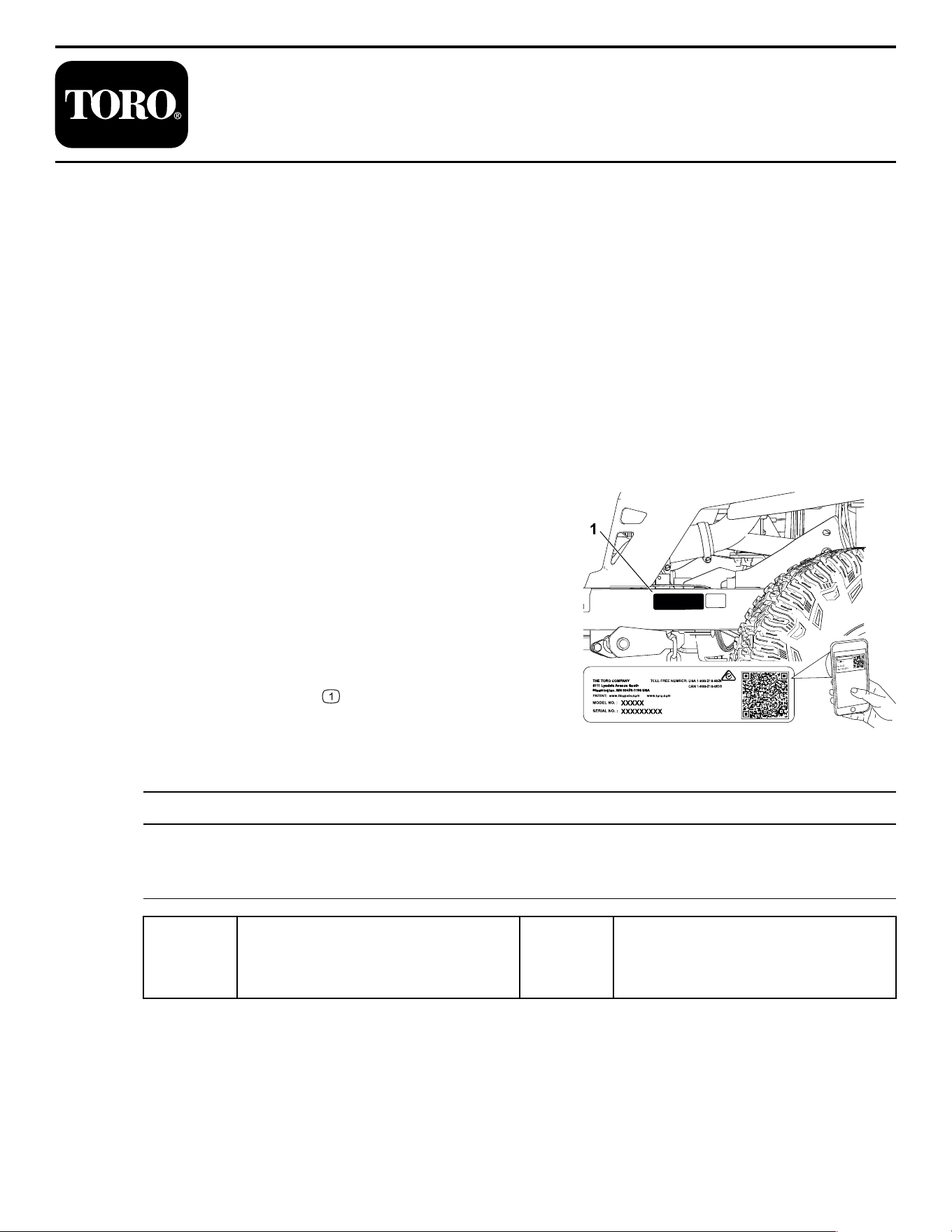
Getting Help
G451770
Visit www.Toro.com for product safety and
operation training materials, accessory
information, help finding a dealer, or to register
your product.
Whenever you need service, genuine Toro parts,
or additional information, contact an Authorized
Service Dealer or Toro Customer Service and have
the model and serial numbers of your product
ready. These numbers are located on the serial
plate on your product
. Write the numbers in the
space provided.
IMPORTANT
With your mobile device, you can scan the QR code on the serial number decal (if
equipped) to access warranty, parts, and other product information.
Model
Number:
Serial
Number:
3464-621 A Page 1–1 Introduction

Manual Conventions
This manual identifies potential hazards and has safety messages identified by the safety-
alert symbol, which signals a hazard that may cause serious injury or death if you do not
follow the recommended precautions.
G405934
This manual uses 2 words to highlight information. Important calls attention to special
mechanical information and Note emphasizes general information worthy of special
attention.
Safety Alert Classifications
The safety-alert symbol shown in this manual and on the machine identifies important safety
messages that you must follow to prevent accidents.
Safety-alert symbol appears above information that alerts you to unsafe actions or situations
and is followed by the word DANGER, WARNING, or CAUTION.
DANGER
Danger indicates an imminently hazardous situation which, if not avoided, will result
in death or serious injury.
WARNING
Warning indicates a potentially hazardous situation which, if not avoided, could result
in death or serious injury.
CAUTION
Caution indicates a potentially hazardous situation which, if not avoided, may result
in minor or moderate injury.
Introduction: Manual Conventions Page 1–2 3464-621 A

Chapter 2
Safety
General Safety
This product is capable of amputating hands and feet and of throwing objects. Always follow
all safety instructions to avoid serious personal injury or death.
• Read, understand, and follow the instructions and warnings in this Operator’s Manual
and on the machine, engine, and attachments before starting the engine.
• Do not allow children or untrained people to operate or service the machine. Allow only
people who are responsible, trained, familiar with the instructions, and physically capable
to operate or service the machine.
• Keep bystanders, particularly children, away from the operating area.
• Do not operate the machine near drop-offs, ditches, embankments, water, or other
hazards, or on slopes greater than 15°.
• Do not put your hands or feet near moving parts.
• Do not operate the machine without all safety shields, guards, switches, and other
devices in place and working properly.
• Park the machine on a level surface, disengage the drives, engage the parking brake,
shut off the engine, remove the key, and wait for all moving parts to stop before leaving
the operator’s position.
• Wait for the machine to cool before servicing, adjusting, fueling, cleaning, or storing it.
3464-621 A Page 2–1 Safety
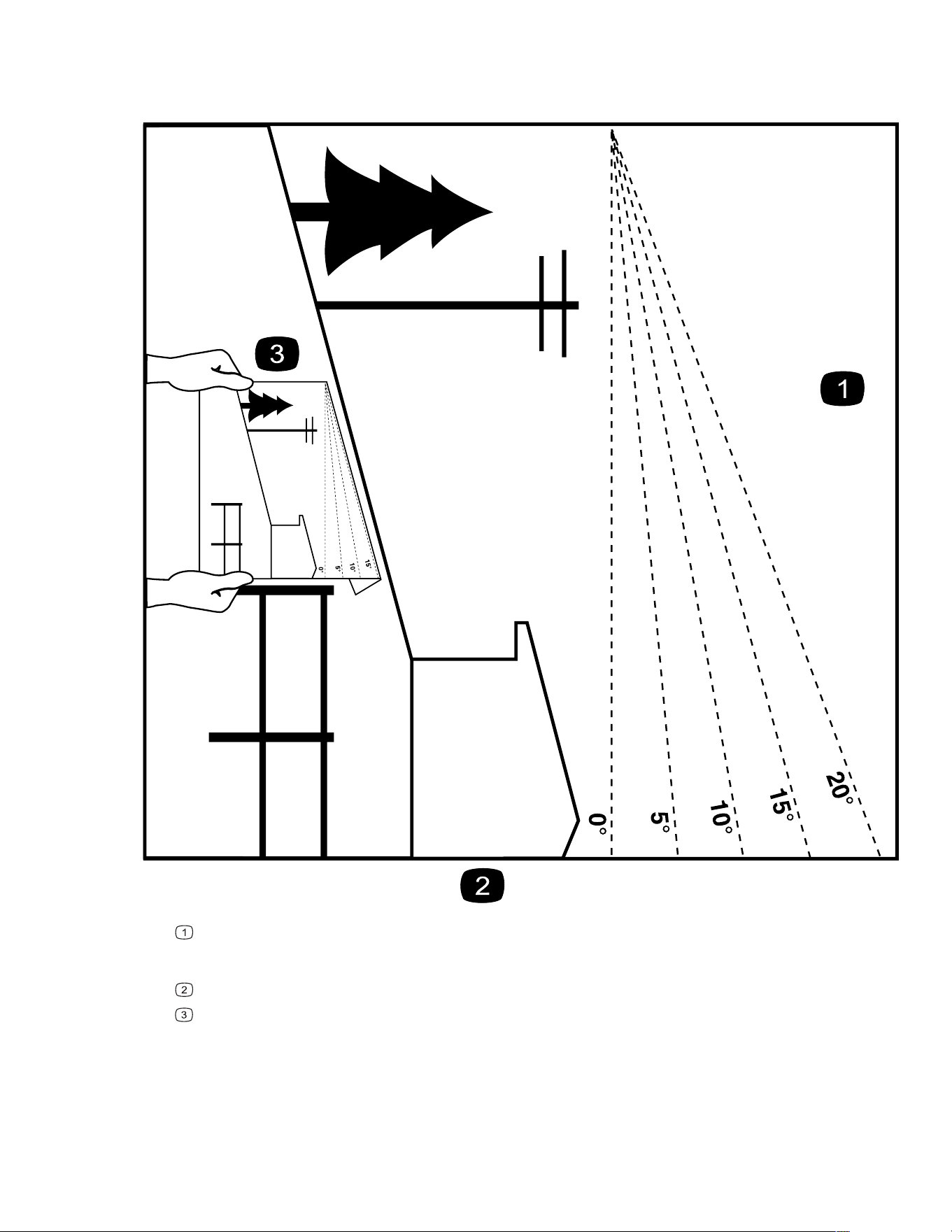
Slope Indicator
You may copy this page for personal use.
G011841s
The maximum slope you can operate the machine on is 15 degrees. Use the slope chart to determine the degree
of slope of hills before operating. Do not operate this machine on a slope greater than 15 degrees. Fold along
the appropriate line to match the recommended slope.
Align this edge with a vertical surface, a tree, building, fence pole, etc.
Example of how to compare slope with folded edge
Safety: Slope Indicator Page 2–2 3464-621 A
Safety and Instructional Decals
Safety decals and instructions are easily visible to the operator and are located near any area
of potential danger. Replace any decal that is damaged or missing.
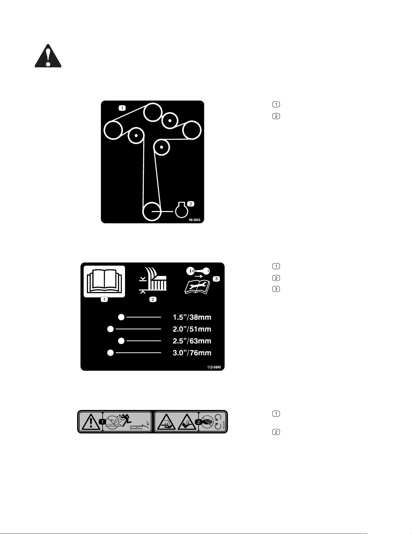
Decal Part: 99-3943
s_decal99-3943
Belt routing
Engine
Decal Part: 112-9840
s_decal112-9840
Read the Operator's Manual.
Height of cut
Remove the ignition key and read
the instructions before servicing or
performing maintenance.
Decal Part: 130-0731
s_decal130-0731
Warning—thrown object hazard;
keep the deflector in place.
Cutting hazard of hand or foot,
mower blade—keep away from moving
parts.
3464-621A Page 2–3 Safety: Safety and Instructional Decals
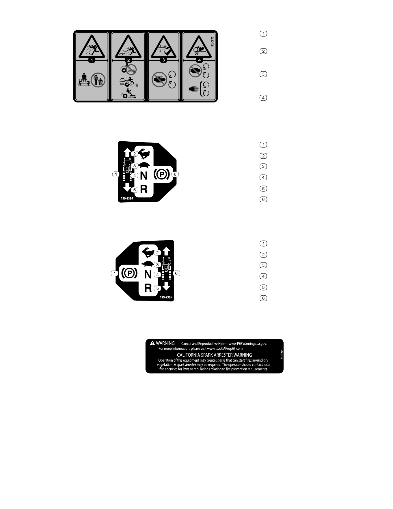
Decal Part: 132-0872
s_decal132-0872
Thrown object hazard—keep
bystanders away.
Thrown object hazard, mower—do
not operate the machine with an open
deck; use a bagger or a deflector.
Cutting/dismemberment hazard of
hands or feet, mower blade—stay away
from moving parts.
Entanglement hazard of hands,
belt—stay away from moving parts;
keep all guards and shields in place.
Decal Part: 139-2394
s_decal139-2394
Traction controls
Fast
Slow
Neutral
Reverse
Parking brake
Decal Part: 139-2395
s_decal139-2395
Parking brake
Fast
Slow
Neutral
Reverse
Traction controls
Decal Part: 142-5864
decal142-5864
Safety: Safety and Instructional Decals Page 2–4 3464-621 A
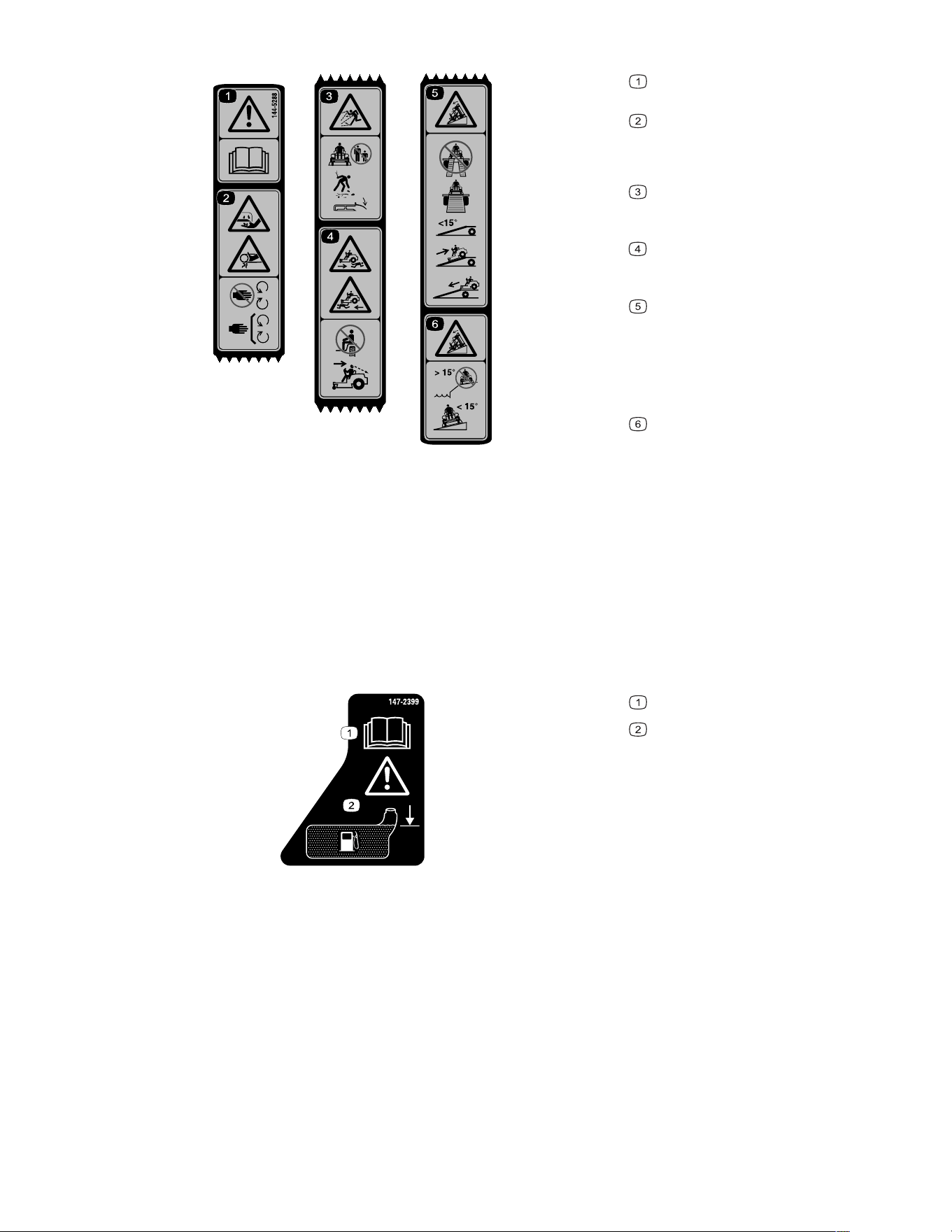
Decal Part: 144-5288
s_decal144-5288
Warning—read the Operator’s
Manual.
Cutting/dismemberment hazard of
the fingers or hand—keep hands away
from moving parts; keep all guards and
shields in place.
Thrown object hazard—keep
bystanders away; pick up debris; keep
the deflector in place.
Runover hazard—do not carry
passengers; look behind you and down
when moving in reverse.
Tipping hazard—when loading onto
a trailer, do not use dual ramps; only
use a singular ramp wide enough for the
machine; do not use a ramp with a
slope greater than 15°; back up the
ramp (in reverse) and drive forward off
the ramp.
Tipping hazard—do not use the
machine near drop-offs with slopes
greater than 15°; only operate across
slopes less than 15°.
Note: This machine complies with the industry standard stability test in the static lateral and
longitudinal tests with the maximum recommended slope indicated on the decal. Review the
instructions for operating the machine on slopes in the Operator’s Manual as well as the
conditions in which you would operate the machine to determine whether you can operate
the machine in the conditions on that day and at that site. Changes in the terrain can result
in a change in slope operation for the machine.
Decal Part: 147-2399
s_decal147-2399
Read the Operator’s Manual.
Warning—Fill to bottom of filler
neck; warning–do not overfill the tank.
3464-621A Page 2–5 Safety: Safety and Instructional Decals

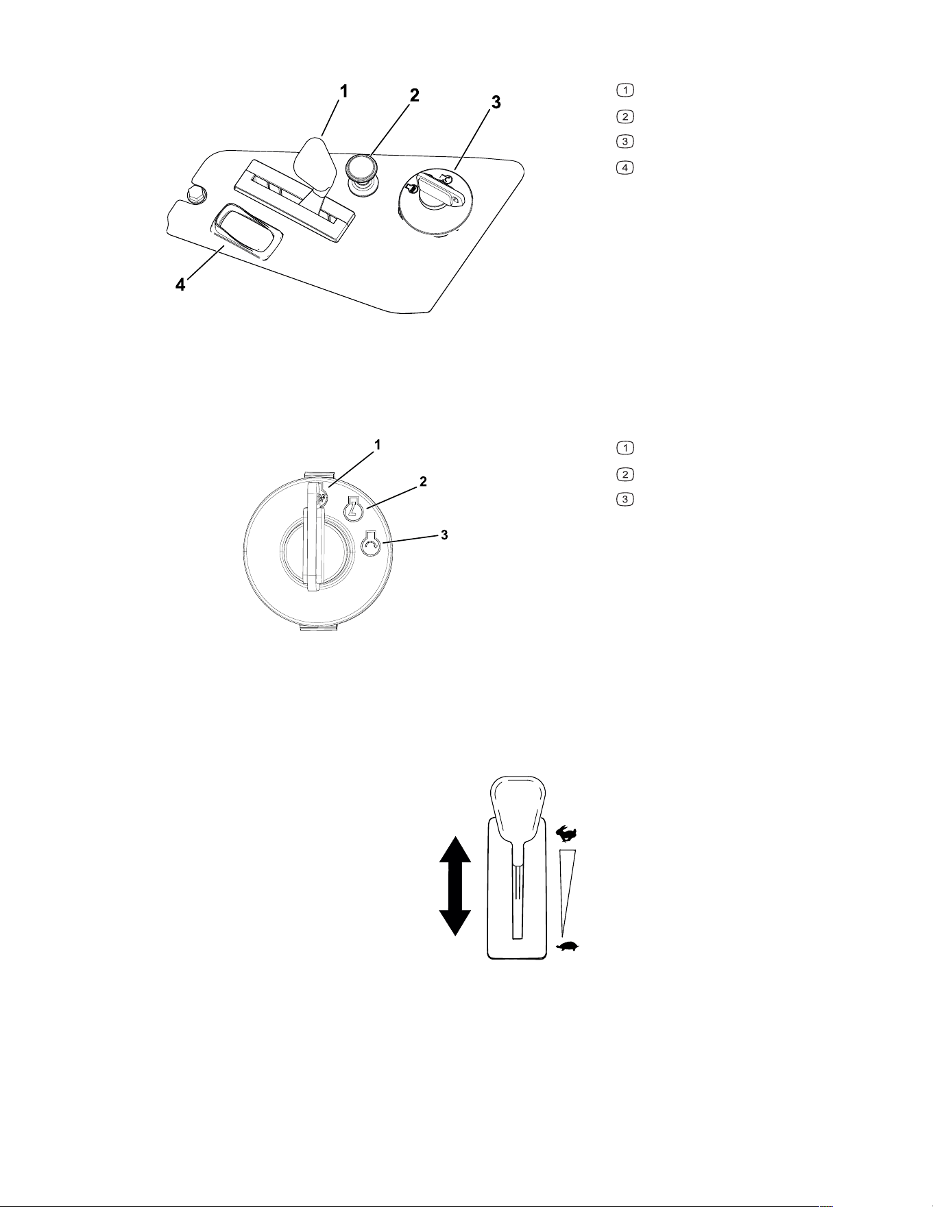
Control Panel
G450844
Throttle control
Choke control
Key switch
Blade-control switch (power
takeoff)
Key Switch
Use the key switch to start or shut off the machine.
G375755s
Shut off the engine
Run the engine
Start engine
Throttle Control
The throttle controls the engine speed, and it has a continuous-variable setting from the
S
LOW to FAST position.
G450843
3464-621A Page 3–2 Product Overview: Control Panel
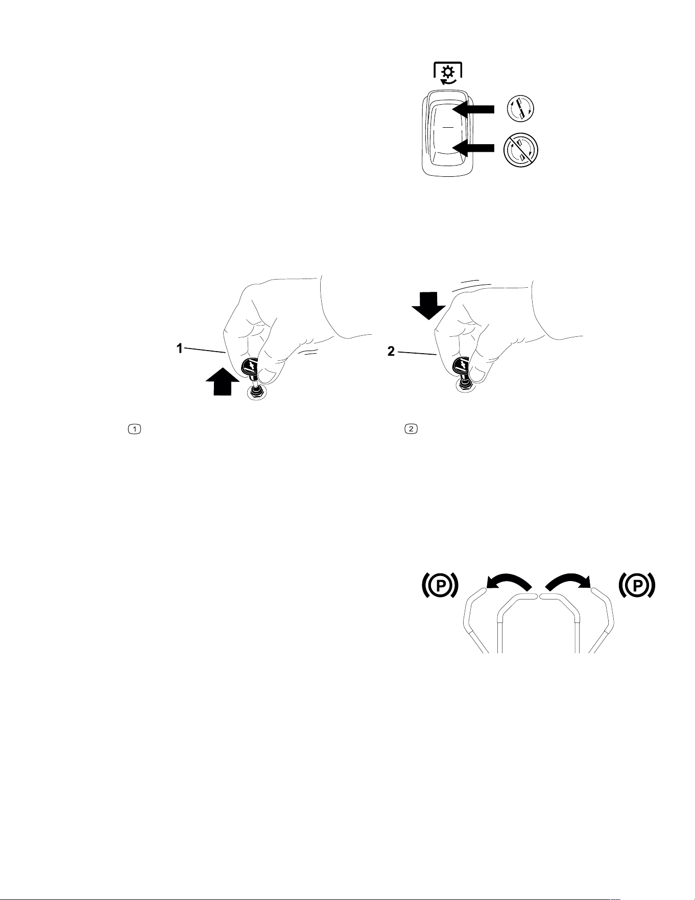
Blade-Control (PTO) Switch
G428617
The blade-control switch, represented by a power-
takeoff (PTO) symbol, engages and disengages
power to the mower blades.
Choke Control
Use the choke control to aid in starting a cold engine.
G419508
Engaged
Disengaged
Motion-Control Levers
Use the motion-control levers to drive the machine forward, reverse, and turn either
direction.
Park Position
G438246
Move the motion-control levers outward from the
center to the P
ARK position to engage the parking
brake when stopping or exiting the machine.
Product Overview: Control Panel Page 3–3 3464-621 A
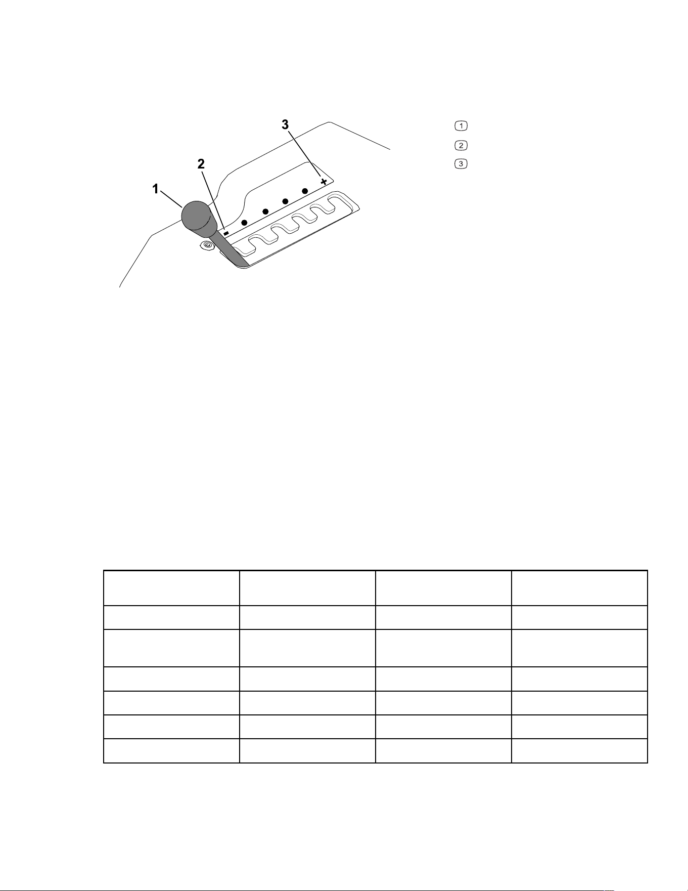
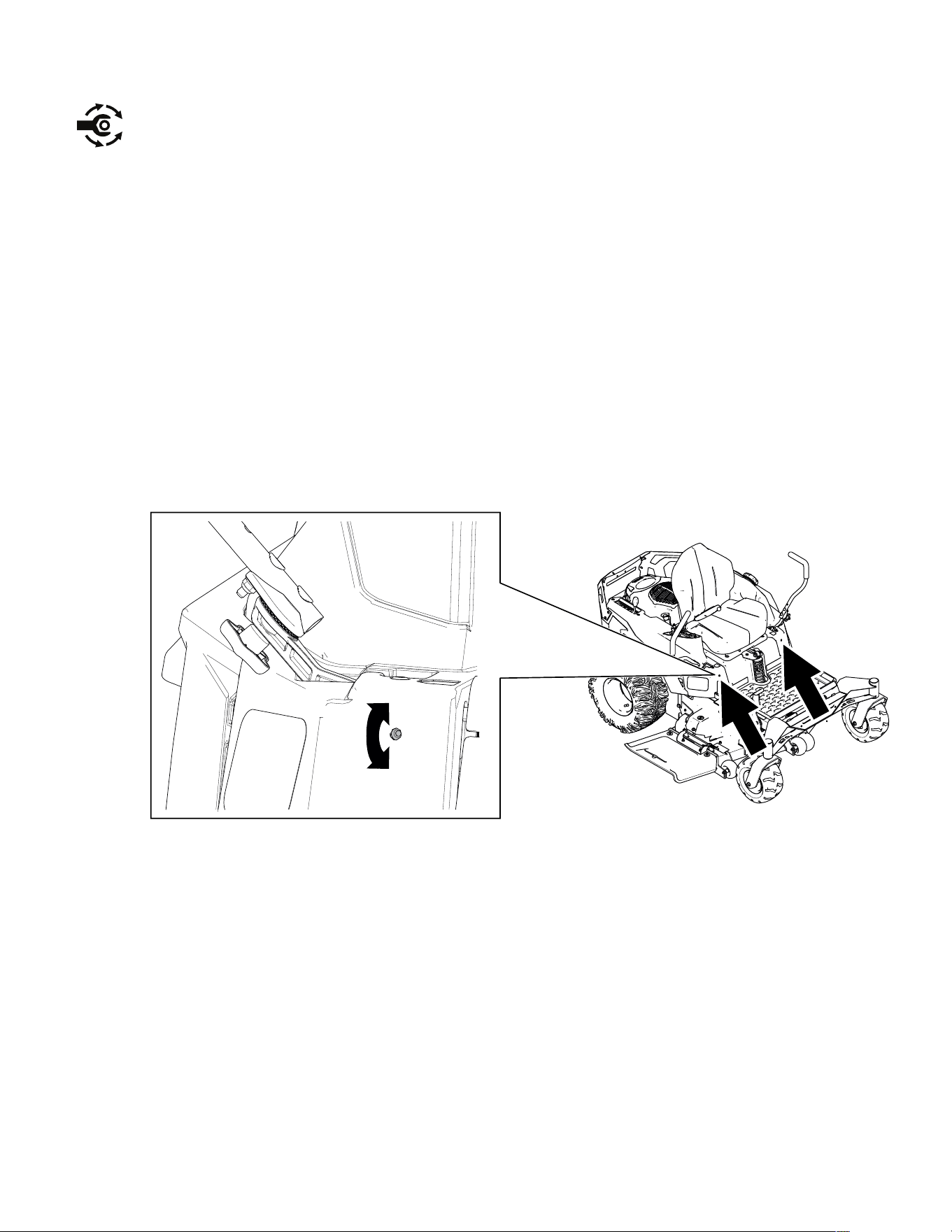
MyRide® Suspension Adjustment Lever
For Machines with the MyRide Suspension System
Use the adjustment lever to adjust the seat suspension for a smooth and comfortable ride.
G292102s
Adjustment lever
Softer suspension
Firmer suspension
Height-of-Cut Pin
The height-of-cut pin works with the foot pedal to lock the deck in a specific cutting height.
Adjust the height of cut only when the machine is not moving.
Deck-Lift Pedal
Use the deck-lift pedal to briefly raise the mower deck from the seated position to avoid
obstacles or when adjusting the height of cut.
Specifications
Note: Specifications and design are subject to change without notice.
Model 77501 Model 77502 and
77515TA
Model 77520TA
Cutting width 127 cm (50 inches) 127 cm (50 inches) 134 cm (54 inches)
Width with deflector
down
156 cm (61-1/2
inches)
156 cm (61-1/2
inches)
166 cm (65-1/2
inches)
Width with deflector up 130 cm (51 inches) 130 cm (51 inches) 140 cm (55 inches)
Length 203 cm (80 inches) 203 cm (80 inches) 203 cm (80 inches)
Height 116 cm (45-1/2 inches) 119 cm (47 inches) 116 cm (45-1/2 inches)
Weight 292 kg (644 lb) 310 kg (684 lb) 310 kg (684 lb)
3464-621A Page 3–4 Product Overview: MyRide® Suspension Adjustment Lever

Attachments/Accessories
A selection of Toro approved attachments and accessories is available for use with the
machine to enhance and expand its capabilities. Contact your Authorized Service Dealer or
authorized Toro distributor or go to www.Toro.com for a list of all approved attachments and
accessories.
To ensure optimum performance and continued safety certification of the machine, use only
genuine Toro replacement parts and accessories.
Product Overview: Specifications Page 3–5 3464-621 A

Chapter 4
Operation
Before Operation
Before Operation Safety
• Do not allow children or untrained people to operate or service the machine. Local
regulations may restrict the age of the operator. The owner is responsible for training all
operators and mechanics.
• Inspect the area where you will use the machine and remove all objects that could be
thrown or could interfere with the operation of the machine.
• Evaluate the terrain to determine the appropriate equipment and any attachments or
accessories required to operate the machine properly and safely.
• Do not carry passengers on the machine.
• Become familiar with the safe operation of the equipment, operator controls, and safety
signs.
• Check that operator-presence controls, safety switches, and guards are attached and
working properly. Do not operate the machine unless they are functioning properly.
• Wear appropriate clothing, including eye protection; long pants; substantial, slip-resistant
footwear; and hearing protection. Tie back long hair and do not wear loose clothing or
loose jewelry.
• Do not operate the machine unless all guards and safety devices, such as the deflectors
and the entire grass catcher, are in place and functioning properly. Replace worn or
deteriorated parts when necessary.
• Shut off the engine, remove the key, and wait for all moving parts to stop before leaving
the operator’s position. Wait for the machine to cool before servicing, adjusting, fueling,
cleaning, or storing it.
WARNING
Contacting the blade can result in serious personal injury.
When you shut off the engine, the blade(s) should stop. If not, stop using your
machine immediately and contact an Authorized Service Dealer.
• Before mowing, inspect the machine to ensure that the cutting assemblies are working
properly.
• Keep bystanders, particularly children, and pets away from the machine during
operation. Shut off the machine and attachment(s) if anyone enters the area.
3464-621 A Page 4–1 Operation

Before Operation Safety (continued)
Fuel Safety
• Fuel is extremely flammable and highly explosive. A fire or explosion from fuel can burn
you and others and can damage property.
– To prevent a static charge from igniting the fuel, place the container and/or machine
directly on the ground before filling, not in a vehicle or on an object.
– Fill the fuel tank outdoors on level ground, in an open area, and when the engine is
cold. Wipe up any fuel that spills.
– Do not handle fuel when smoking or around an open flame or sparks.
– Do not remove the fuel cap or add fuel to the tank while the engine is running or hot.
– If you spill fuel, do not attempt to start the engine. Avoid creating a source of ignition
until the fuel vapors have dissipated.
– Store fuel in an approved container and keep it out of the reach of children.
• Do not overfill the fuel tank. Replace the fuel cap and tighten it securely.
• In certain conditions during fueling, static electricity can be released, causing a spark that
can ignite fuel vapors.
• Do not fill containers inside a vehicle or on a truck or trailer bed with a plastic liner.
Always place containers on the ground and away from your vehicle before filling.
• Remove the equipment from the truck or trailer and refuel it while it is on the ground. If
this is not possible, then refuel from a portable container rather than from a fuel-
dispenser nozzle.
• Keep the fuel-dispenser nozzle in contact with the rim of the fuel tank or container
opening at all times until fueling is complete. Do not use a nozzle lock-open device.
• Fuel is harmful or fatal if swallowed. Long-term exposure to vapors can cause serious
injury and illness.
– Avoid prolonged breathing of vapors.
– Keep your hands and face away from the nozzle and the fuel-tank opening.
– Keep fuel away from your eyes and skin.
• Clean up any spilled fuel.
• Do not store the machine or fuel container where there is an open flame, spark, or pilot
light, such as on a water heater or on other appliances.
• Do not operate the machine without the entire exhaust system in place and in proper
working condition.
Operation: Before Operation Page 4–2 3464-621 A
Fuel
Fuel Specifications
Capacity 19 L (5 US gallons)
Type Unleaded gasoline
Minimum octane rating 87 (US) or 91 (research octane; outside the US)
Ethanol No more than 10% by volume
Methanol None
MTBE (methyl tertiary butyl ether) Less than 15% by volume
Oil Do not add to the fuel
Use only clean, fresh (no more than 30 days old), fuel from a reputable source.
IMPORTANT
To reduce starting problems, add fuel stabilizer/conditioner to fresh fuel as directed
by the fuel-stabilizer/conditioner manufacturer.
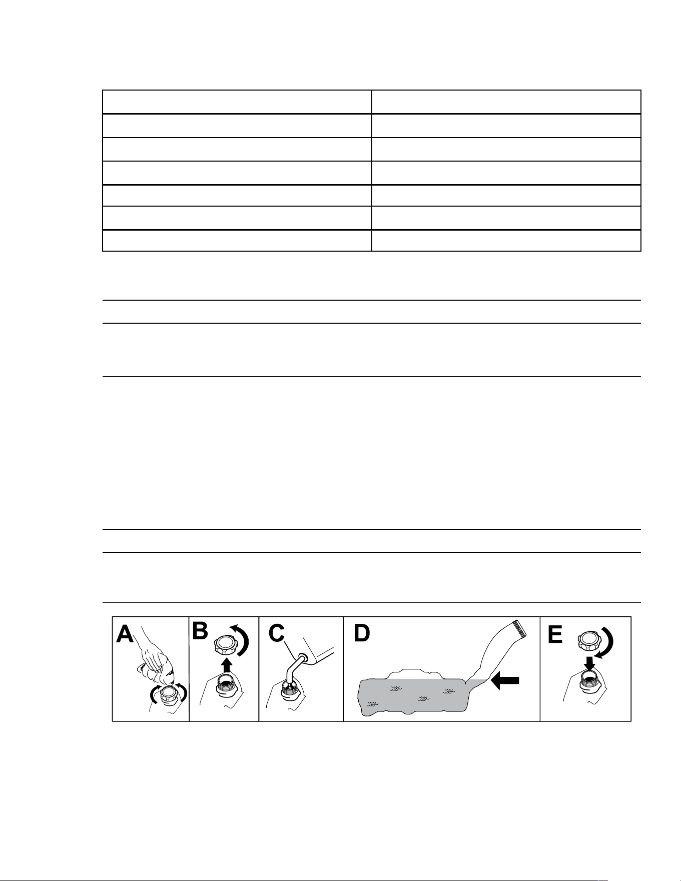
Filling the Fuel Tank
1. Park the machine on a level surface.
2. Move the motion-control levers outward to the P
ARK position.
3. Shut off the engine and remove the key.
4. Clean around the fuel-tank cap and fill the fuel tank.
IMPORTANT
Fill the fuel tank to the bottom of the filler neck. Do not fill the fuel tank completely
full.
G450855
Performing Daily Maintenance
Before starting the machine each day, perform the Each Use/Daily procedures listed in the
Maintenance Schedule.
3464-621A Page 4–3 Operation: Before Operation
Break-In Time
New engines take time to develop full power. Mower decks and drive systems have higher
friction when new, placing additional load on the engine. Allow 40 to 50 hours of break-in
time for new machines to develop full power and best performance.
Safety-Interlock System
The safety-interlock system is designed to prevent the engine from starting unless:
• The blade-control switch (PTO) is disengaged.
• The motion-control levers are in the P
ARK position.
The safety-interlock system also is designed to shut off the engine whenever the control
levers are out of the P
ARK position and you rise from the seat.
WARNING
If the safety-interlock switches are disconnected or damaged, the machine could
operate unexpectedly, causing personal injury.
• Do not tamper with the interlock switches.
• Check the operation of the interlock switches daily and replace any damaged
switches before operating the machine.
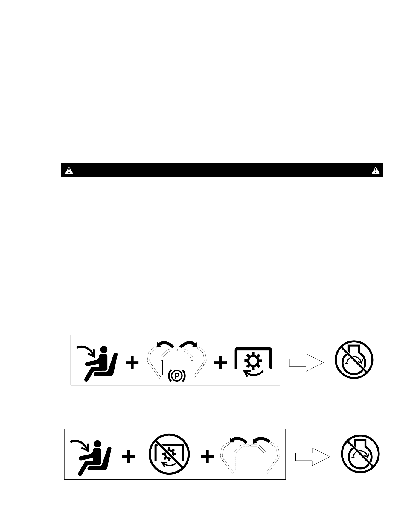
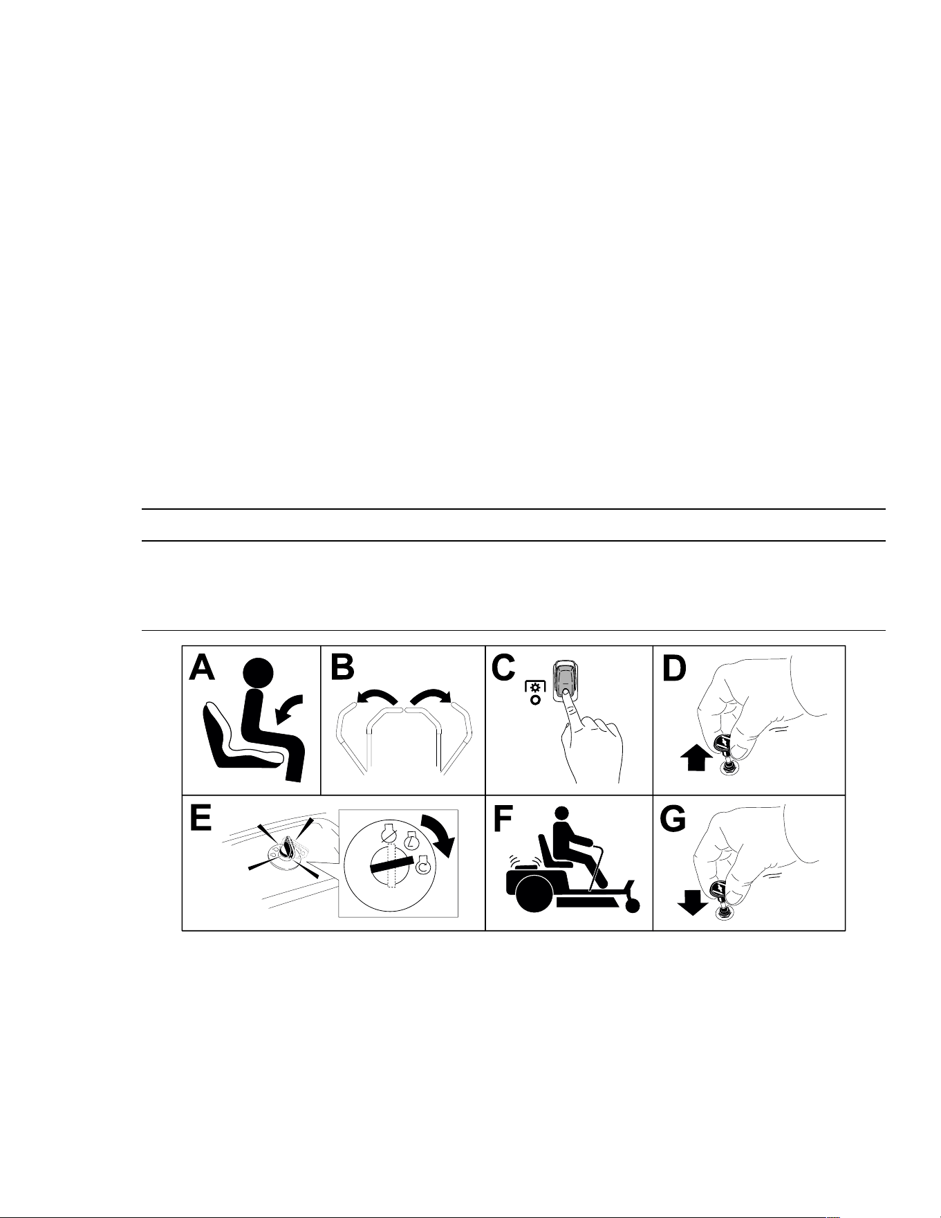
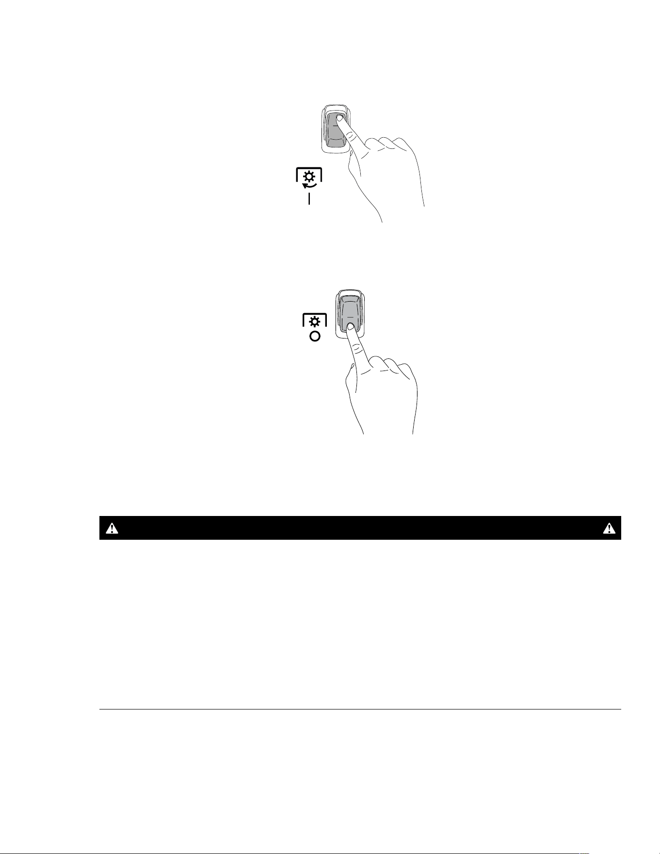
Testing the Safety-Interlock System
Test the safety-interlock system before you use the machine each time. If the safety system
does not operate as described below, have an Authorized Service Dealer repair the safety
system immediately.
1. Sit on the seat, move the motion-control levers to the P
ARK position, and move the blade-
control switch to the O
N position. Try starting the engine; the engine should not crank.
G451953
2. Sit on the seat and move the blade-control switch to the OFF position. Move either
motion-control lever to the center, unlocked position. Try starting the engine; the engine
should not crank. Repeat with the other motion-control lever.
G451952
Operation: Before Operation Page 4–4 3464-621 A
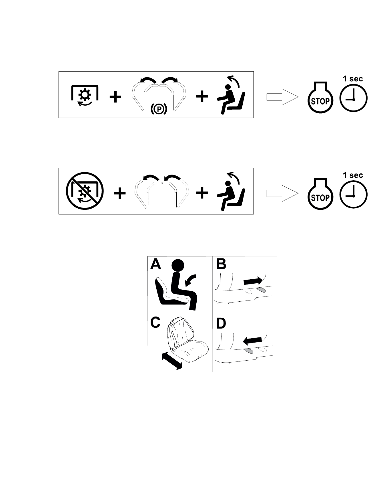
Safety-Interlock System (continued)
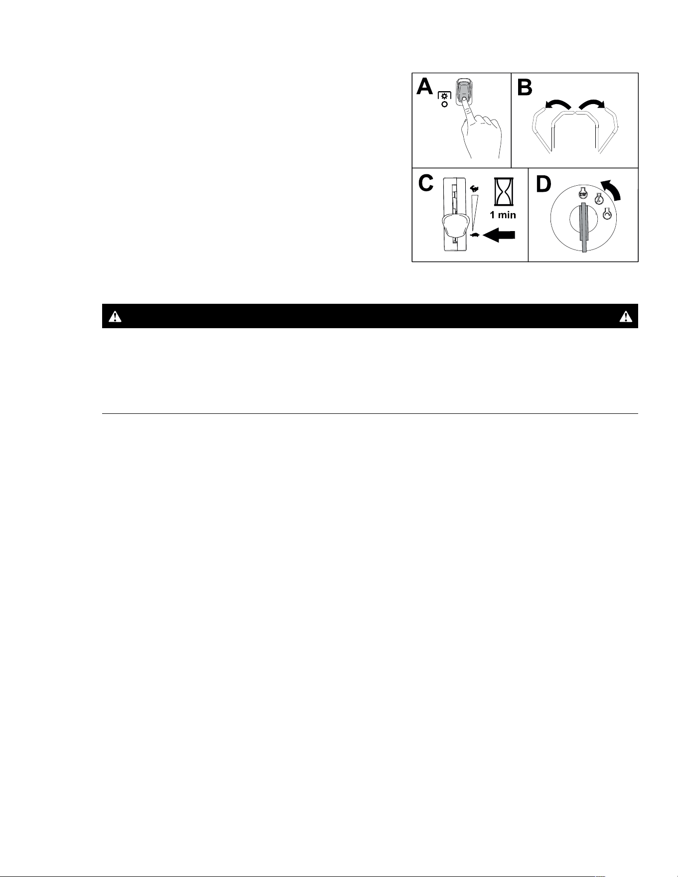
3. Sit on the seat, move the blade-control switch to the OFF position, and move the motion-
control levers to the P
ARK position. Start the engine. While the engine is running, engage
the blade-control switch, and rise slightly from the seat; the engine should shut off within
1 second.
G451951
4. Sit on the seat, move the blade-control switch to the OFF position, and move the motion-
control levers to the P
ARK position. Start the engine. While the engine is running, move
the motion-control levers to the center, unlocked position and rise slightly from the seat;
the engine should shut off within 1 second.
G451950
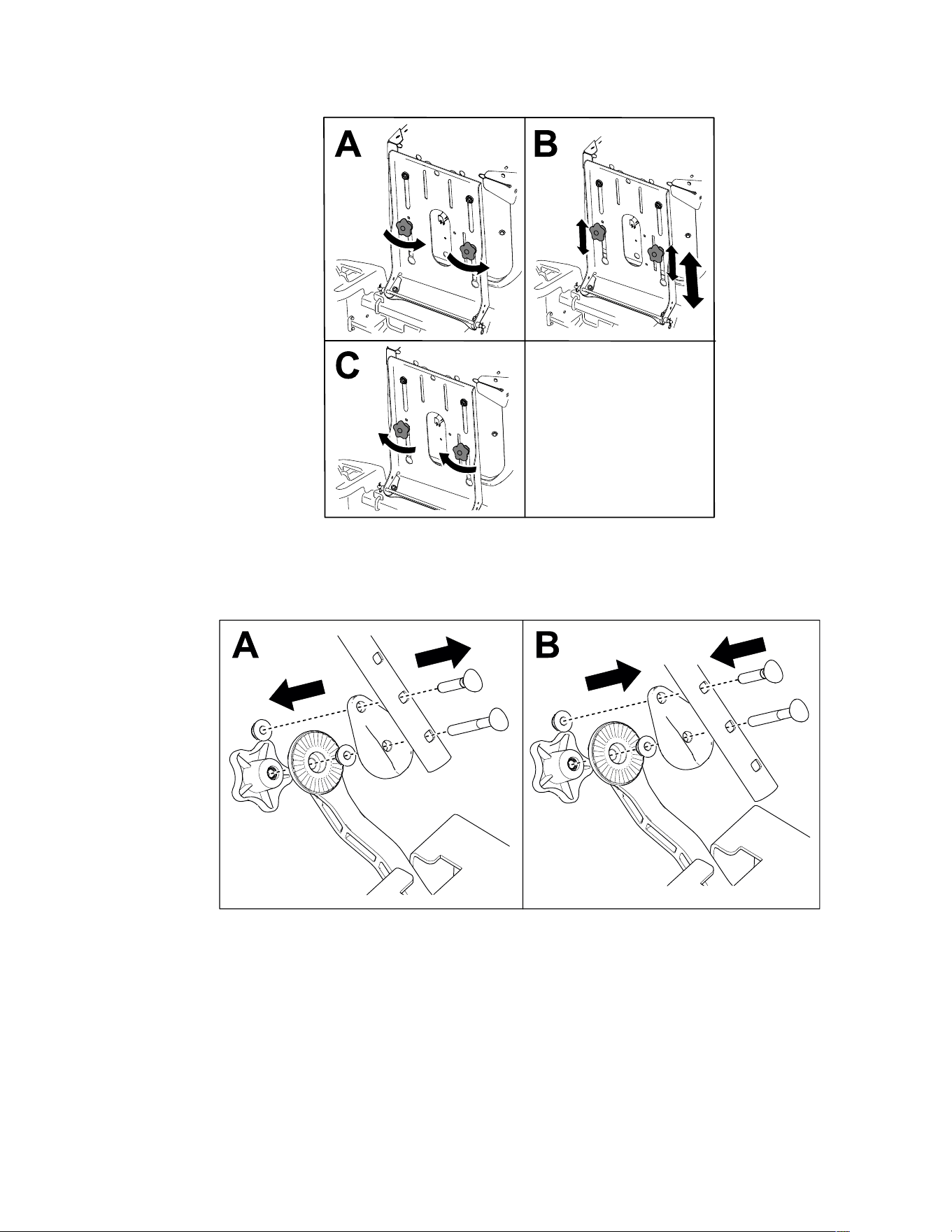
Positioning the Seat
Machines with MyRide Suspension
G451798
3464-621A Page 4–5 Operation: Before Operation

Adjusting the Motion-Control Lever Tilt
Adjust the motion-control levers forward or rearward for your comfort.
G439363
1. Loosen the knob.
2. Pivot the control lever forward or rearward.
3. Tighten the knob.
4. Repeat the adjustment for the other control
lever.
During Operation
During Operation Safety
• The owner/operator can prevent and is responsible for accidents that may cause
personal injury or property damage.
• Use your full attention while operating the machine. Do not engage in any activity that
causes distractions; otherwise, injury or property damage may occur.
• Do not operate the machine while ill, tired, or under the influence of alcohol or drugs.
• Do not operate the machine unless all guards and safety devices, such as the deflectors
and the entire grass catcher, are in place and functioning properly. Replace worn or
deteriorated parts with genuine Toro parts when necessary.
• Operating engine parts, especially the muffler, can become extremely hot. Severe burns
can occur on contact and debris, such as leaves, grass, brush, etc. can catch fire. Keep
the engine area free from debris and excessive oil and grease.
• Operate the engine only in well-ventilated areas. Exhaust gases contain carbon
monoxide, which is lethal if inhaled.
• Operate the machine only in good visibility and appropriate weather conditions. Do not
operate the machine when there is the risk of lightning.
• Start the engine with your feet well away from the blades.
• Keep your hands and feet away from moving parts. Keep clear of the discharge opening.
• Keep away from holes, ruts, bumps, rocks, and other hazards. Use care when
approaching blind corners, shrubs, trees, tall grass or other objects that may hide
obstacles or obscure your view.
• Do not mow with the discharge deflector raised, removed, or altered unless there is a
grass-collection system or mulch kit in place and working properly.
3464-621A Page 4–7 Operation: Before Operation

During Operation Safety (continued)
• Do not mow in reverse unless it is absolutely necessary. Always look down and behind
you before moving the machine in reverse.
• Stop the blades whenever you are not mowing. Slow down the machine, and use caution
when crossing surfaces other than grass or when transporting the machine to and from
the operating area.
• Be aware of the mower discharge path and direct the discharge away from others. Avoid
discharging material against a wall or obstruction because the material may ricochet
back toward you.
• If the machine strikes an object or starts to vibrate, immediately shut off the engine,
remove the key, and wait for all moving parts to stop before examining the machine for
damage. Make all necessary repairs before resuming operation.
• Slow down and use caution when making turns and crossing roads and sidewalks with
the machine. Always yield the right-of-way.
• Never leave a running machine unattended.
• Before you leave the operating position, do the following:
– Park the machine on a level surface.
– Disengage the power takeoff and lower the attachments.
– Engage the parking brake.
– Shut off the engine and remove the key.
– Wait for all moving parts to stop.
• Never carry children on the machine.
• Do not carry children on the machine, even when the blades are not moving. Children
could fall off and be seriously injured or prevent you from safely operating the machine.
Children who have been given rides in the past could appear in the operating area
without warning and be run over or backed over by the machine.
• Children are often attracted to the machine and the mowing activity. Never assume that
children will remain where you last saw them.
• Keep children out of the operating area and under the watchful care of a responsible
adult other than the operator.
• Be alert and shut off the machine if children enter the operating area.
• Before backing up or turning the machine, look down and all around for small children.
• Do not use the machine as a towing vehicle unless it has a hitch installed. Attach towed
equipment to the machine only at the hitch point.
• Use only accessories and attachments approved by The Toro® Company.
Slope Safety
• Slopes are a major factor related to loss of control and rollover accidents, which can
result in severe injury or death. The operator is responsible for safe slope operation.
Operating the machine on any slope requires extra caution. Before using the machine on
a slope, do the following:
– Review and understand the slope instructions in the manual and on the machine.
Operation: During Operation Page 4–8 3464-621 A
During Operation Safety (continued)
– Use an angle indicator to determine the approximate slope angle of the area.
– Never operate on slopes greater than 15°.
– Evaluate the site conditions of the day to determine if the slope is safe for machine
operation. Use common sense and good judgment when performing this evaluation.
Changes in the terrain, such as moisture, can quickly affect the operation of the
machine on a slope.
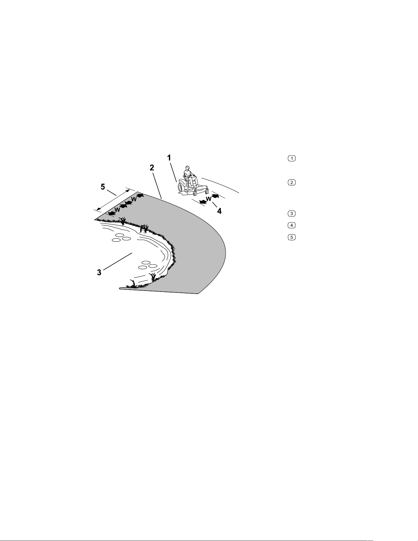
• Identify hazards at the base of the slope. Do not operate the machine near drop-offs,
ditches, embankments, water, or other hazards. The machine could suddenly roll over if
a wheel goes over the edge or the edge collapses. Keep a safe distance (twice the width
of the machine) between the machine and any hazard. Use a walk-behind machine or a
hand trimmer to mow the grass in these areas.
G229111s
Safe Zone—use the machine
here on slopes less than 15° or flat
areas.
Danger Zone—use a walk-
behind mower and/or a hand
trimmer on slopes greater than 15°
and near drop-offs or water.
Water
W = Width of the machine
Keep a safe distance (twice the
width of the machine) between the
machine and any hazard.
• Avoid starting, stopping, or turning the machine on slopes. Avoid making sudden
changes in speed or direction; turn slowly and gradually.
• Do not operate a machine under any conditions where traction, steering, or stability is in
question. Be aware that operating the machine on wet grass, across slopes, or downhill
may cause the machine to lose traction. Loss of traction to the drive wheels may result in
sliding and a loss of braking and steering. The machine can slide even if the drive wheels
are stopped.
• Remove or mark obstacles such as ditches, holes, ruts, bumps, rocks, or other hidden
hazards. Tall grass can hide obstacles. Uneven terrain could overturn the machine.
• Use extra care while operating with accessories or attachments, such as grass-collection
systems. These can change the stability of the machine and cause a loss of control.
Follow directions for counterweights.
• If possible, keep the deck lowered to the ground while operating on slopes. Raising the
deck while operating on slopes can cause the machine to become unstable.
3464-621A Page 4–9 Operation: During Operation
During Operation Safety (continued)
Towing Safety
• Do not attach towed equipment except at the hitch point.
• Do not use the machine as a towing vehicle unless it has a hitch installed.
• Do not exceed the maximum gross towing weight.
• Never allow children or others near the towed equipment.
• On slopes, the weight of the towed equipment may cause loss of traction, increased risk
of rollover, and loss of control. Reduce the towed weight and slow down.
• The stopping distance may increase with the weight of a towed load. Travel slowly and
allow extra distance to stop.
• Make wide turns to keep the attachment clear of the machine.
Starting the Engine
Start the engine as shown.
Note: A warm or hot engine may not require choking.
IMPORTANT
Do not engage the starter for more than 5 seconds at a time, otherwise you can
damage the starter motor. If the engine fails to start, wait 15 seconds before operating
the engine starter again.
G451068
Operation: During Operation Page 4–10 3464-621 A
Shutting Off the Engine
G451067
1. Disengage the blades by moving the blade-
control switch to the O
FF position.
2. Move the motion-control levers outward to the
P
ARK position.
3. Move the throttle control to the S
LOW position
and let the engine idle for 1 minute.
4. Turn the key to the O
FF position and remove
the key.
CAUTION
Children or bystanders may be injured if they move or attempt to operate the machine
while it is unattended.
Always remove the key and engage the parking brake when leaving the machine
unattended.
3464-621A Page 4–11 Operation: During Operation
Driving the Machine
CAUTION
Positioning one lever too far in front of the other causes the machine to spin very
rapidly. As a result, you may lose control of the machine, causing personal injury to
you and damage to the machine.
Slow down the machine before making sharp turns.
The drive wheels turn independently, powered by motors on each axle. You can turn 1 side
in reverse while you turn the other forward, causing the machine to spin rather than turn.
This greatly improves the machine maneuverability but may require some time for you to
adapt to how it moves.
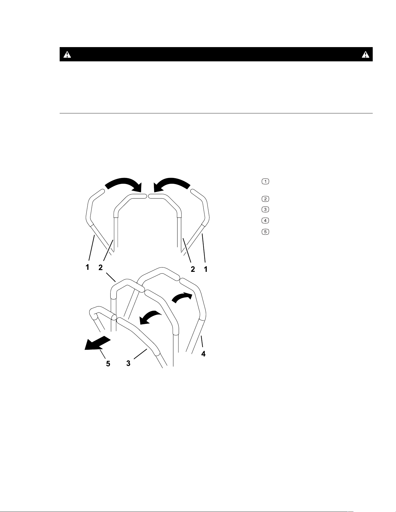
1. Move the motion-control levers down to the center, unlocked position.
G426843s
Motion-control levers—PARK
position
Center, unlocked position
Forward
Reverse
Front of the machine
Operation: During Operation Page 4–12 3464-621 A
Driving the Machine (continued)
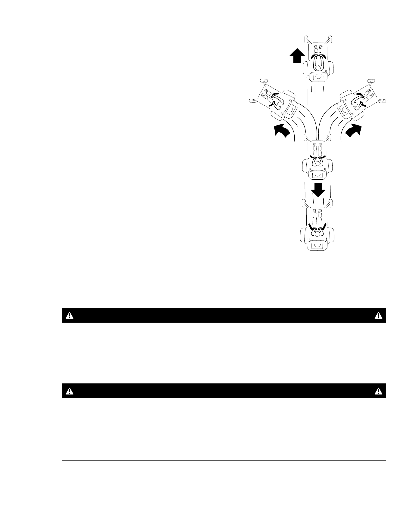
G397314s
2. Slowly push the motion-control levers forward
or rearward. Move 1 lever farther than the
other lever to turn.
Note: The farther you move the motion-
control levers, the faster the machine moves in
that direction.
3. To stop, pull the motion-control levers back to
the N
EUTRAL position.
Operating the Mower Blade-Control Switch (PTO)
DANGER
The rotating blades under the mower deck are dangerous. Blade contact will cause
serious injury or death.
Do not put your hands or feet under the mower or mower deck when the blades are
engaged.
DANGER
An uncovered discharge opening allows objects to be thrown toward you or
bystanders. Also, contact with the blade could occur. Thrown objects or blade
contact will cause serious injury or death.
Do not operate the mower with the discharge deflector raised, removed, or altered
unless a grass collection system or mulch kit is in place and working properly.
1. Move the throttle control to the F
AST position.
3464-621A Page 4–13 Operation: During Operation
Operating the Mower Blade-Control Switch (PTO)
(continued)
2. Engage the blade-control switch.
G450387
3. Mow as desired.
4. Disengage the blade-control switch.
G450388
Side Discharge
The hinged grass deflector disperses clippings to the side and down toward the turf.
DANGER
Without the grass deflector, discharge cover, or complete grass catcher assembly
mounted in place, you and bystanders are exposed to blade contact and thrown
debris. Contact with rotating mower blade(s) and thrown debris will cause injury or
death.
• Do not remove the grass deflector from the machine, because the grass deflector
routes material down toward the turf. If the grass deflector is ever damaged,
replace it immediately.
• Never try to clear the discharge area or mower blades unless the power takeoff
(PTO) is off. Rotate the key to the O
FF position and remove the key.
Operation: During Operation Page 4–14 3464-621 A
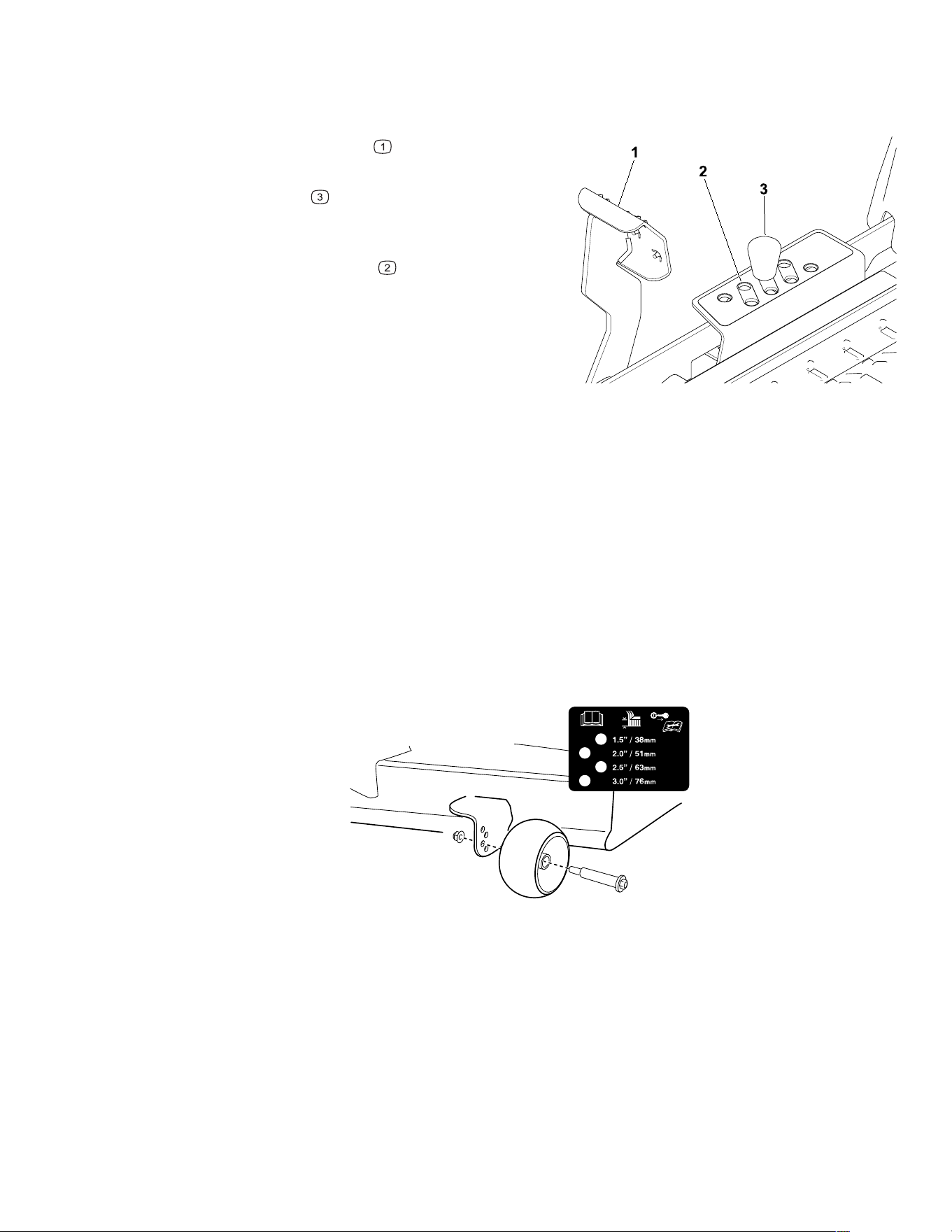
Adjusting the Height of Cut
You can adjust the height of cut from 38 to 127 mm (1-1/2 to 5 inches) in 13 mm (1/2 inch)
increments.
G440390
1. Push the deck-lift pedal with your foot to
raise the mower deck.
2. Remove the pin
from the height-of-cut
bracket.
3. Insert the pin into the hole corresponding to
the desired height of cut
.
4. Lower the deck slowly until the lever contacts
the pin.
Adjusting the Anti-Scalp Rollers
Whenever you change the height of cut, adjust the height of the anti-scalp rollers.
1. Park the machine on a level surface, disengage the blade-control switch, and move the
motion-control levers outward to the P
ARK position.
2. Shut off the engine, remove the key, and wait for all moving parts to stop before leaving
the operating position.
3. Adjust the anti-scalp rollers to match the closest height-of-cut position.
Note: Adjust the anti-scalp rollers so that the rollers do not touch the ground in normal,
flat mowing areas.
G454259
Operating Tips
Maximize Air Circulation
For best mowing and maximum air circulation, operate the engine at the FAST position. Air
circulation is required to thoroughly cut grass clippings, so do not set the height-of-cut so low
as to totally surround the mower deck in uncut grass. Always try to have 1 side of the mower
deck free from uncut grass, which allows air to be drawn into the mower deck.
3464-621A Page 4–15 Operation: During Operation

Operating Tips (continued)
Avoid Cutting Too Low
When mowing uneven ground, raise the cutting height to slightly higher than normal to avoid
scalping the turf. However, the cutting height used in the past is generally the best one to
use. When cutting grass longer than 15 cm (6 inches) tall, you may want to cut the lawn
twice to ensure an acceptable quality of cut.
Cut a Third of the Grass Blade
It is best to cut only about a third of the grass blade. Cutting more than that is not
recommended unless grass is sparse, or it is late fall when grass grows more slowly.
Alternate the Mowing Direction
Alternate the mowing direction to keep the grass standing straight. This also helps disperse
clippings, which enhances decomposition and fertilization.
Mowing Frequency
Grass grows at different rates at different times of the year. To maintain the same cutting
height, mow more often in early spring. As the grass growth rate slows in mid summer, mow
less frequently. If you cannot mow for an extended period, first mow at a high cutting height,
then mow again 2 days later at a lower height setting.
Mow at Slower Ground Speeds
In certain conditions, mowing at a slower ground speed can improve cut quality.
Avoid Grass Clumps
If you must stop driving forward while mowing, a clump of grass clippings may drop onto
your lawn. To avoid this, move onto a previously cut area with the blades engaged or
disengage the mower deck while moving forward.
Keep the Underside of the Mower Deck Clean
Clean clippings and dirt from the underside of the mower deck after each use. Grass and dirt
build-up will eventually decrease the cutting quality.
Maintain the Blades
Maintain a sharp blade throughout the cutting season because a sharp blade cuts cleanly
without tearing or shredding the grass blades. Tearing and shredding turns grass brown at
the edges, which slows growth and increases the chance of disease. Check the mower
blades after each use for sharpness, and for any wear or damage. File down any nicks and
sharpen the blades as necessary. If a blade is damaged or worn, replace it.
Operation: During Operation Page 4–16 3464-621 A

After Operation
After Operation Safety
• Park the machine on a level surface, disengage the drives, engage the parking brake,
shut off the engine, remove the key, and wait for all moving parts to stop before leaving
the operator’s position.
• Wait for the machine to cool before servicing, adjusting, fueling, cleaning, or storing it.
• Clean grass, leaves, excessive grease and oil, and other debris from the mower deck,
muffler, drives, grass catcher, and engine area to help prevent fires.
• Close the fuel-shutoff valve (if equipped) before storing or transporting the machine.
• Use full-width ramps for loading the machine into a trailer or truck.
• Tie the machine down securely using straps, chains, cable, or ropes. Both front and rear
straps should be directed down and outward from the machine.
Cleaning the Machine
Clean the machine after each use.
1. Park the machine on a level surface, disengage the blade-control switch, and move the
motion-control levers outward to the P
ARK position.
2. Shut off the engine, remove the key, and wait for all moving parts to stop before leaving
the operating position.
3. Clean grass and debris from cutting unit, muffler, drives, grass catcher, and engine.
IMPORTANT
You can wash the machine with a mild detergent and water. Do not pressure wash the
machine. Avoid excessive use of water, especially near the control panel, under the
seat, around the engine, hydraulic pumps, and motors.
Hauling the Machine
Use a heavy-duty trailer or truck to haul the machine. Use a full-width ramp. Ensure that the
trailer or truck has all the necessary brakes, lighting, and marking as required by law. Please
carefully read all the safety instructions. Knowing this information could help you or
bystanders avoid injury. Refer to your local ordinances for trailer and tie-down requirements.
WARNING
Driving on the street or roadway without turn signals, lights, reflective markings, or a
slow-moving-vehicle emblem is dangerous and can lead to accidents causing
personal injury.
Do not drive the machine on a public street or roadway.
3464-621A Page 4–17 Operation: After Operation
Hauling the Machine (continued)
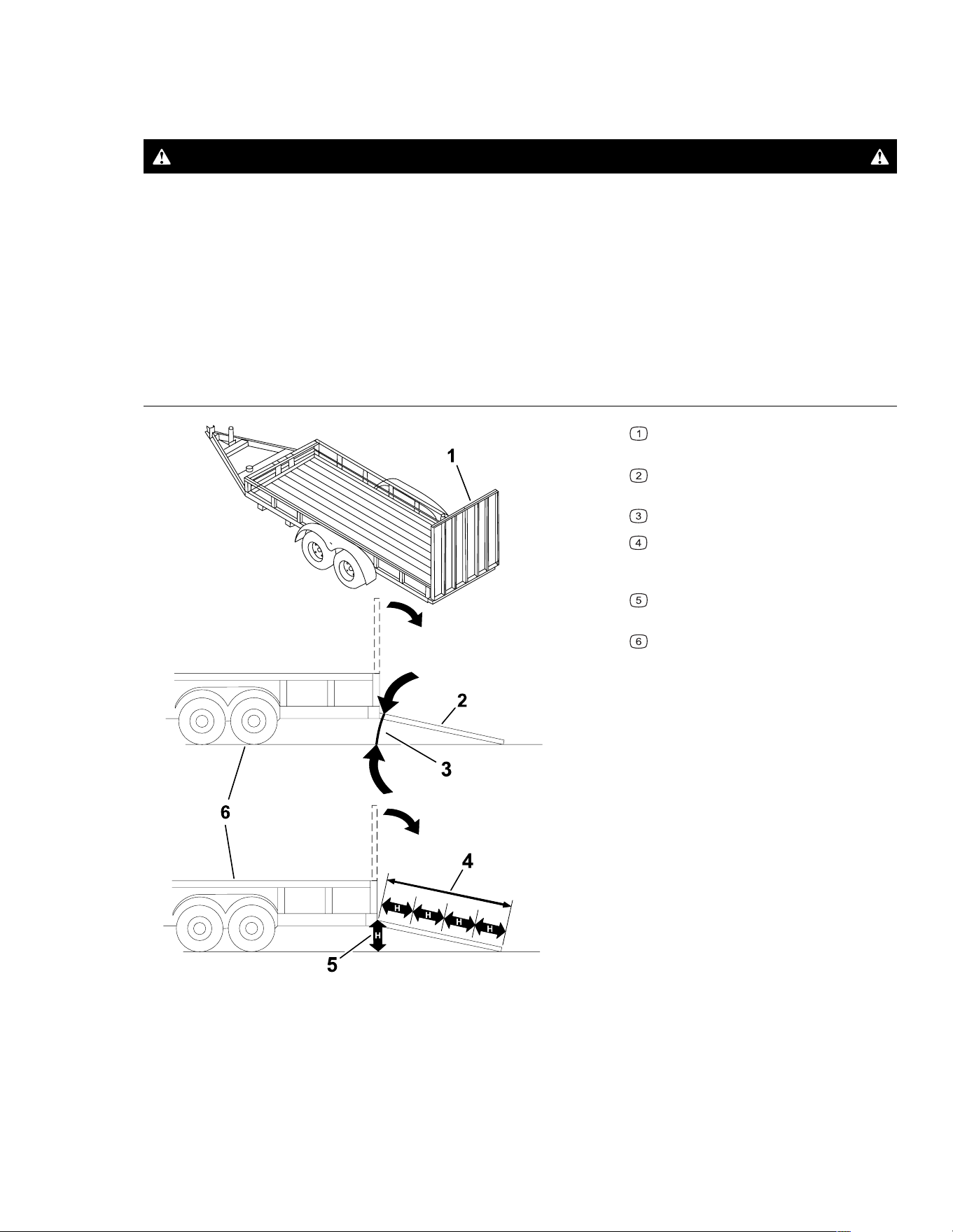
Trailer Requirements
WARNING
Loading a machine onto a trailer or truck increases the possibility of tip-over and
could cause serious injury or death.
• Use only a full-width ramp; do not use individual ramps for each side of the
machine.
• Do not exceed a 15-degree angle between the ramp and the ground or between the
ramp and the trailer or truck.
• Ensure that the length of ramp is at least 4 times as long as the height of the trailer
or truck bed to the ground.
G027996s
Full-width ramp(s) in stowed
position
Side view of full-width ramp in
loading position
Not greater than 15 degrees
Ramp is at least 4 times as long as
the height of the trailer or truck bed to
the ground
H = height of the trailer or truck bed
to the ground
Trailer
Operation: After Operation Page 4–18 3464-621 A
Hauling the Machine (continued)
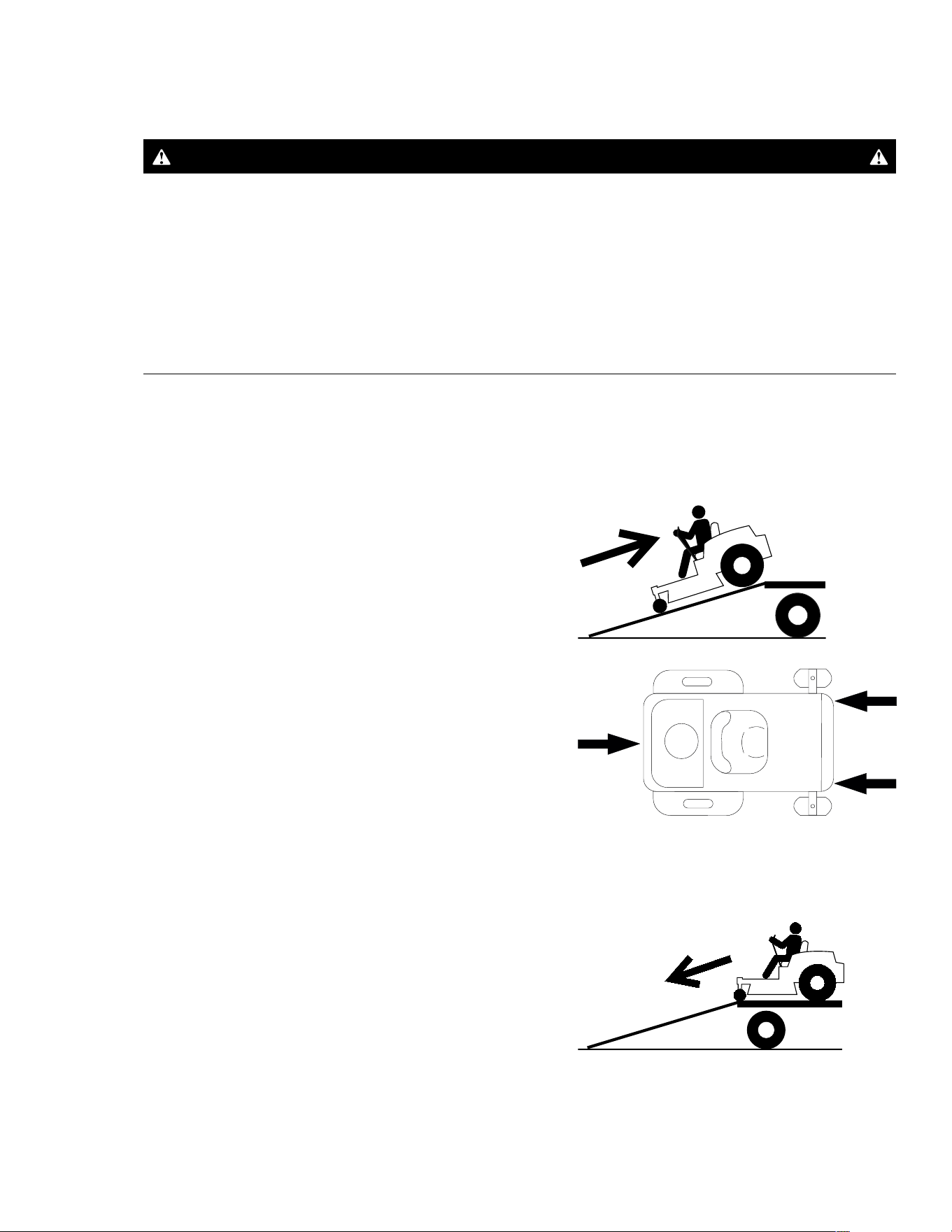
Loading the Machine
WARNING
Loading a machine onto a trailer or truck increases the possibility of tip-over and
could cause serious injury or death.
• Use extreme caution when operating a machine on a ramp.
• Back the machine up the ramp and drive it forward down the ramp.
• Avoid sudden acceleration or deceleration while driving the machine on a ramp as
this could cause a loss of control or a tip-over situation.
1. If using a trailer, connect it to the towing vehicle and connect the safety chains.
2. If applicable, connect the trailer brakes.
3. Lower the ramp, ensuring that the angle between the ramp and the ground does not
exceed 15 degrees.
G414592
4. Back the machine up the ramp.
5. Shut off the engine, remove the key, and move
the motion-control levers outward to the P
ARK
position.
G451313
6. Tie down the machine using straps, chains,
cable, or ropes. Refer to local regulations for
tie-down requirements.
Unloading the Machine
G414593
1. Lower the ramp, ensuring that the angle
between the ramp and the ground does not
exceed 15 degrees.
2. Drive the machine forward down the ramp.
3464-621A Page 4–19 Operation: After Operation

Chapter 5
Maintenance
Maintenance Safety
• If you leave the key in the switch, someone could accidently start the engine and
seriously injure you or other bystanders. Remove the key from the switch before you
perform any maintenance.
• Before you leave the operator’s position, do the following:
– Park the machine on a level surface.
– Disengage the drives.
– Engage the parking brake.
– Shut off the engine and remove the key.
– Wait for the machine to cool before performing maintenance.
• Do not allow untrained personnel to service the machine.
• Keep your hands and feet away from moving parts or hot surfaces. If possible, do not
make adjustments with the engine running.
• Keep all guards, shields, switches, and all safety devices in place and in proper working
condition. Frequently check for worn or deteriorating components and replace them with
genuine Toro parts when necessary.
• Carefully release pressure from components with stored energy.
WARNING
Removing or modifying original equipment, parts, and/or accessories may alter
the warranty, controllability, and safety of the machine. Making unauthorized
modifications to the original equipment or failing to use original Toro parts could
lead to serious injury or death.
• Check the parking brake operation frequently. Adjust and service it as required.
• Never tamper with safety devices. Check their proper operation regularly.
• Clean grass, leaves, excessive grease and oil, and other debris from the cutting unit,
muffler, drives, grass catcher, and engine compartment to prevent fires.
• Clean up oil or fuel spills and remove fuel-soaked debris.
• Do not rely solely on mechanical or hydraulic jacks to support the machine. Use
adequate jack stands.
• Keep all parts in good working condition and all hardware tightened, especially the blade-
attachment hardware.
Maintenance Page 5–1 3464-621 A

• To ensure optimum performance, use only genuine Toro replacement parts and
accessories. Replacement parts and accessories made by other manufacturers could be
dangerous.
Recommended Maintenance Schedule
Maintenance
Service Interval
Maintenance Procedure
After the first 8 hours
Change the engine oil.
After the first 50
hours
Check the lug-nut torque.
Before each use or
daily
Check the safety-interlock system.
Check the air cleaner for dirty, loose, or damaged parts.
Check the engine-oil level.
Clean the air-intake screen.
Inspect the blades.
Inspect the grass deflector for damage.
After each use
Clean grass and debris from the machine.
Clean the mower-deck housing.
Every 25 hours
Grease the caster wheel bearings (more often in sandy soil conditions).
Check the tire pressure.
Check the belts for wear or cracks.
Every 100 hours Change the engine oil (more often in dirty or dusty conditions).
Replace or clean and gap the spark plug.
Replace the in-line fuel filter.
Every 100 hours or
yearly, whichever
comes first
Replace the paper air-cleaner element (more often in dirty or dusty conditions).
Every 200 hours Change the engine-oil filter (more often in dirty or dusty conditions).
Every 300 hours Check and adjust the valve clearance. Contact an Authorized Service Dealer.
Yearly Check the lug-nut torque.
Before storage
Charge the battery and disconnect the battery cables.
Perform all maintenance procedures listed above before storage.
Paint any chipped surfaces.
IMPORTANT
Refer to your engine owner's manual for additional maintenance procedures.
3464-621A Page 5–2 Maintenance: Recommended Maintenance Schedule
Pre-Maintenance Procedures
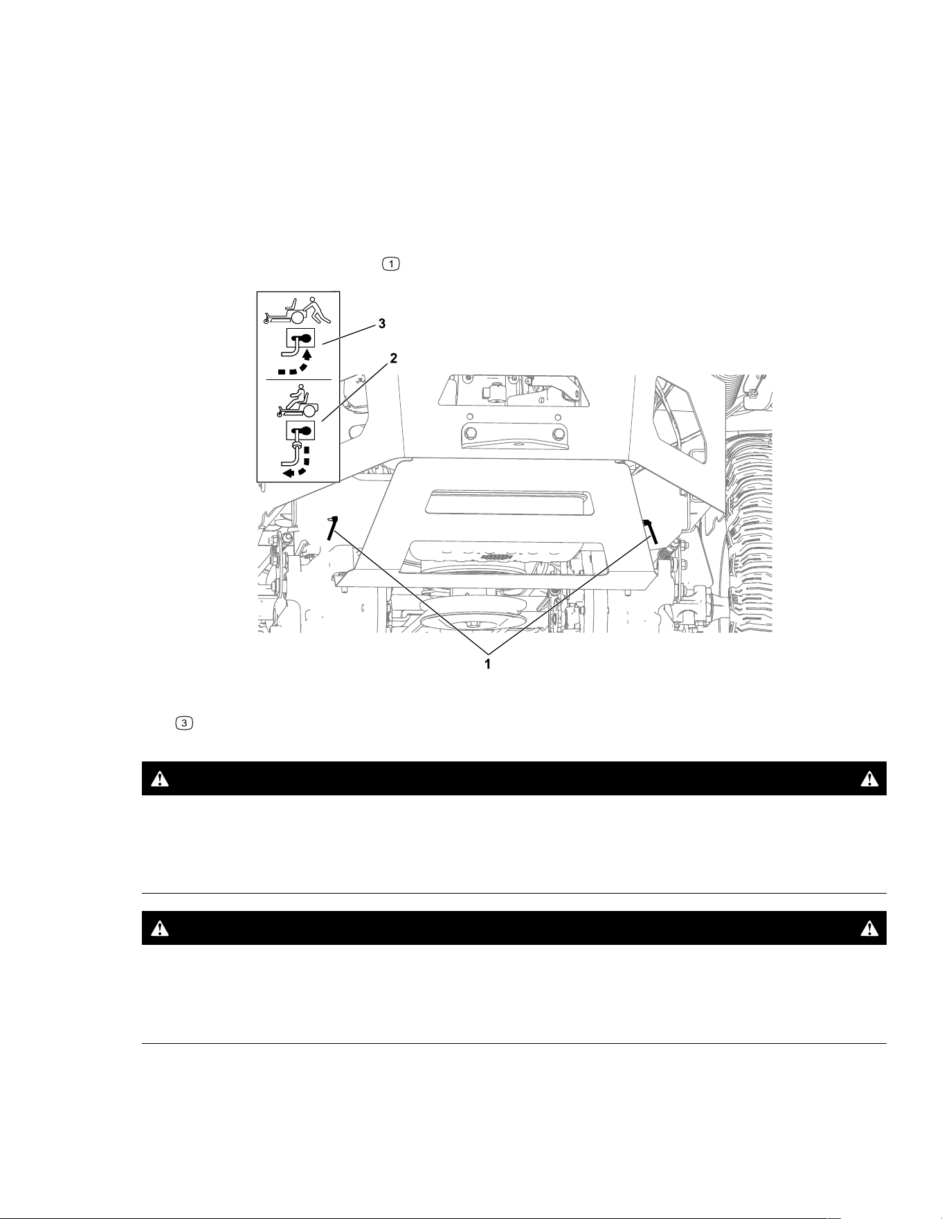
Moving a Non-Functioning Machine
1. Park the machine on a level surface, disengage the blade-control switch, and move the
motion-control levers outward to the P
ARK position.
2. Shut off the engine and wait for all moving parts to stop before leaving the operating
position.
3. Locate the bypass levers
on the frame on both sides of the engine.
G438892
4. Move both bypass levers forward through the slotted hole and over to lock them in place
.
WARNING
Contact with hot surfaces may cause personal injury.
Keep your hands, feet, face, clothing and other body parts away the engine, muffler
and other hot surfaces.
WARNING
The machine could unintentionally move while the bypass levers are locked forward
in the slot and injure you or bystanders.
Lock the bypass levers rearward after moving the machine.
Maintenance: Pre-Maintenance Procedures Page 5–3 3464-621 A
Moving a Non-Functioning Machine (continued)
5. Disengage the parking brake by moving both motion-control levers down to the center,
unlocked position.
Note: Do not start the machine.
6. Move the machine as required.
IMPORTANT
Always push the machine by hand. Do not tow the machine, because towing may
damage it.
7. Move the motion-control levers outward to the P
ARK position.
8. Move both bypass levers rearward and over through the slotted hole to lock them in
place
.
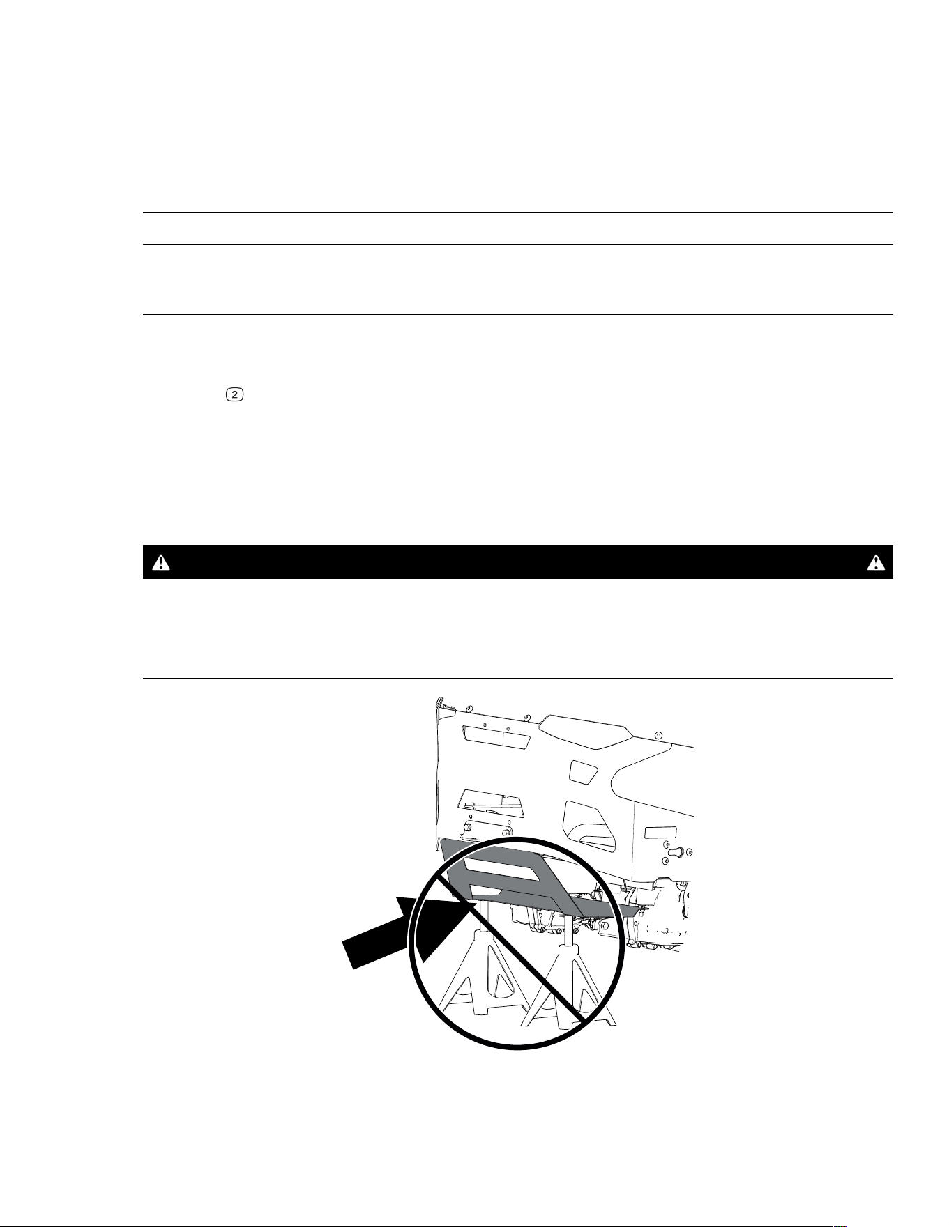
Raising the Machine
Use jackstands to support the machine when you raise it.
WARNING
Supporting the machine on the lower muffler shield may damage the shield and
cause the machine to fall, injuring you or bystanders.
Do not use the lower muffler shield to lift or support the machine.
G451399
3464-621A Page 5–4 Maintenance: Pre-Maintenance Procedures
Lubrication
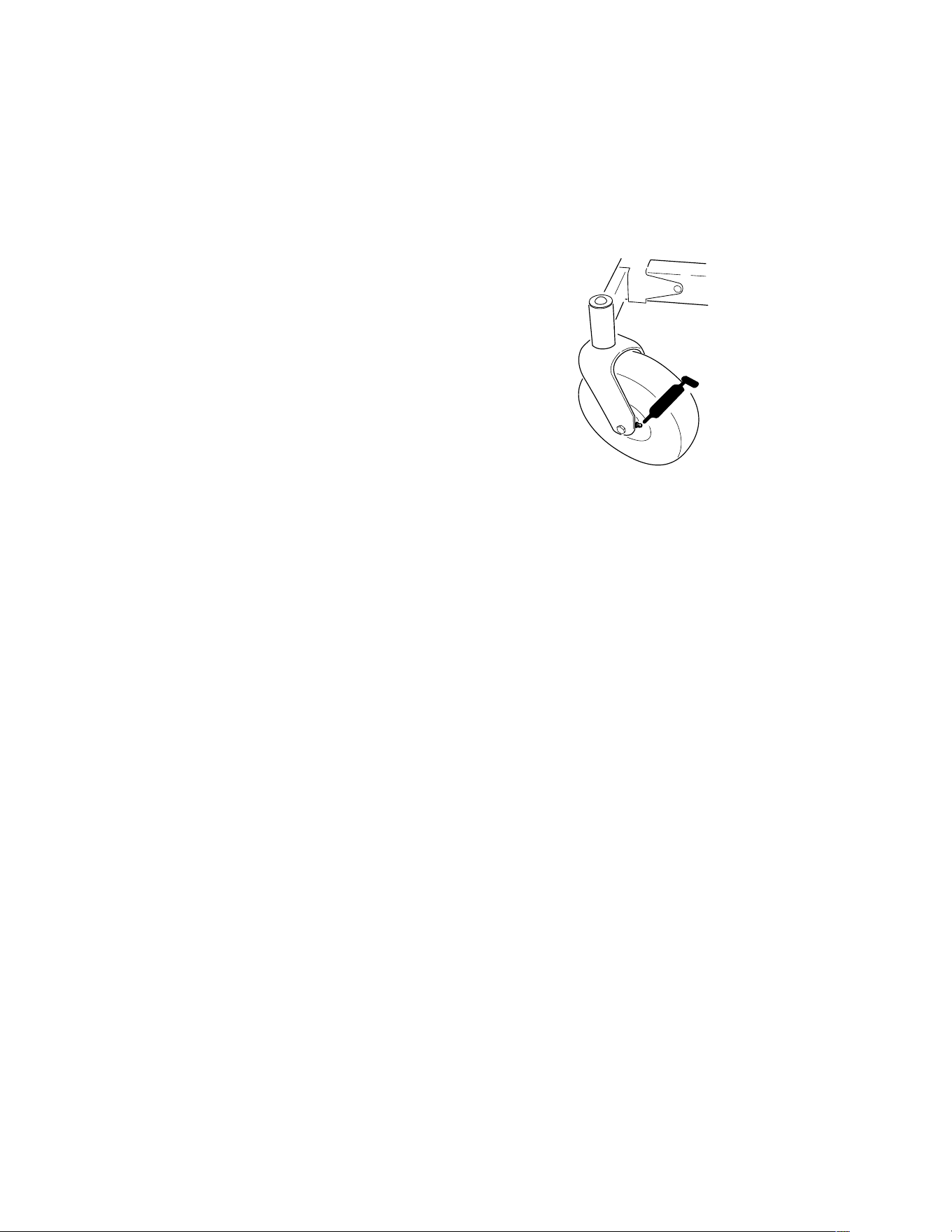
Greasing the Bearings
1. Park the machine on a level surface, disengage the blade-control switch, and move the
motion-control levers outward to the P
ARK position.
2. Shut off the engine and wait for all moving parts to stop before leaving the operating
position.
G451140
3. Clean the grease fittings with a rag.
Note: Scrape any paint off the front of the
fittings.
4. Connect a grease gun to each fitting.
5. Pump grease into the fittings until grease
begins to ooze out of the bearings.
6. Wipe up any excess grease.
Maintenance: Lubrication Page 5–5 3464-621 A
Engine Maintenance
Engine Safety
• Keep your hands, feet, face, other body parts, and clothing away from the muffler and
other hot surfaces. Wait for the engine to cool before performing maintenance.
• Do not change the engine governor speed or overspeed the engine.
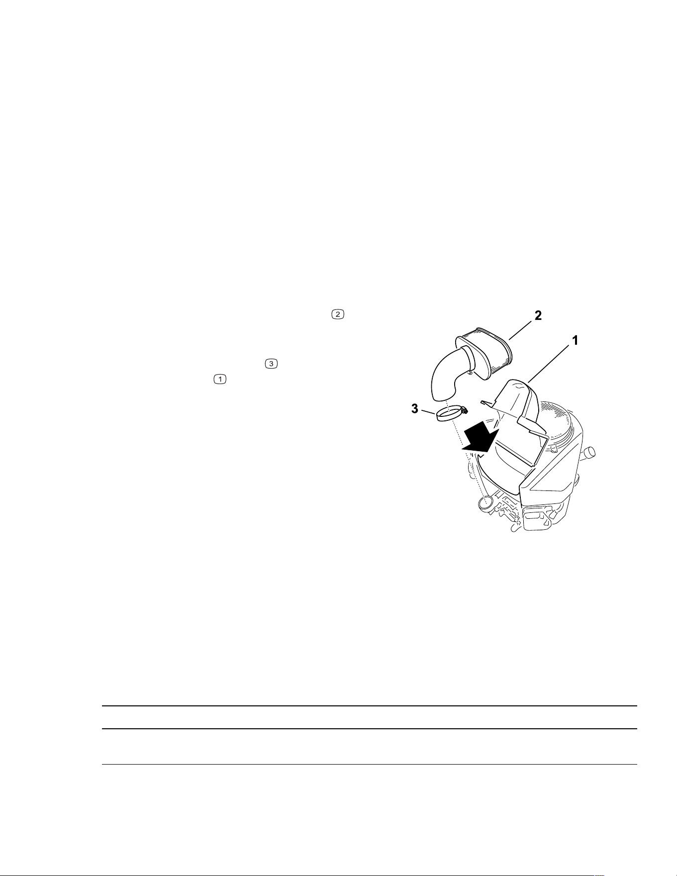
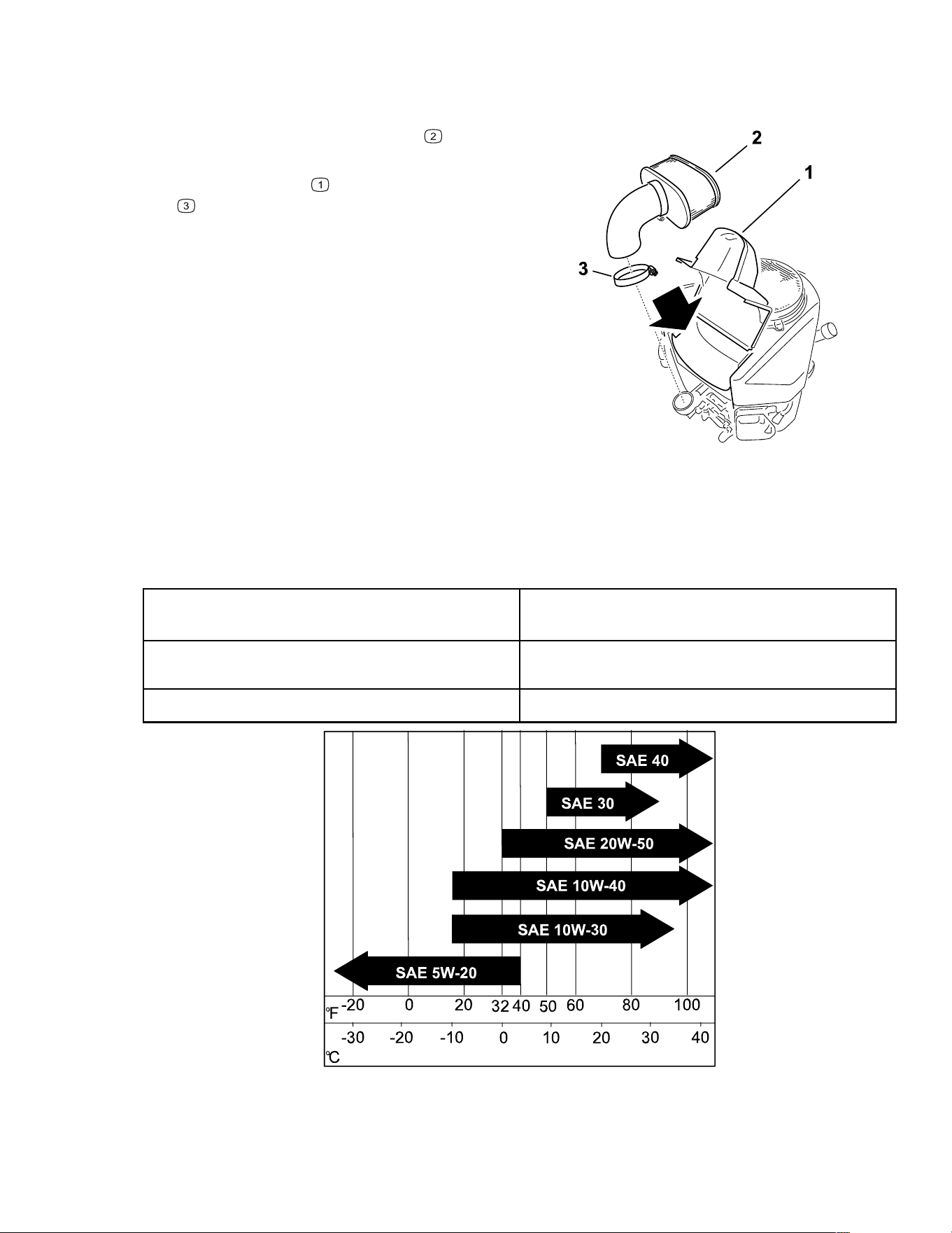
Air Cleaner Service
Removing the Air-Cleaner Element
1. Park the machine on a level surface, disengage the blade-control switch, and move the
motion-control levers outward to the P
ARK position.
2. Shut off the engine and wait for all moving parts to stop before leaving the operating
position.
G207139s
3. Clean around the air-cleaner cover to
prevent dirt from getting into the engine and
causing damage.
4. Loosen the hose clamp
and remove the
paper element
.
Servicing the Paper Air-Cleaner Element
1. Clean the paper element by tapping it gently to remove dust.
Note: If it is very dirty, replace the paper element with a new one.
2. Inspect the element for tears, an oily film, or damage to the rubber seal.
3. Replace the paper element if it is damaged.
IMPORTANT
Do not clean the paper filter.
3464-621A Page 5–6 Maintenance: Engine Maintenance
Air Cleaner Service (continued)
Installing the Air-Cleaner Element
G207139s
1. Install the air-cleaner element onto the air-
cleaner base.
2. Install the cover
and tighten the hose clamp
.
Engine-Oil Service
Engine-Oil Specifications
Oil Type Detergent oil (API service SF, SG, SH, SJ, or
SL)
Crankcase Capacity 1.8 L (61 fl oz); without filter; 2.1 L (70 fl oz) with
filter
Viscosity See the table below
Maintenance: Engine Maintenance Page 5–7 3464-621 A
Engine-Oil Service (continued)
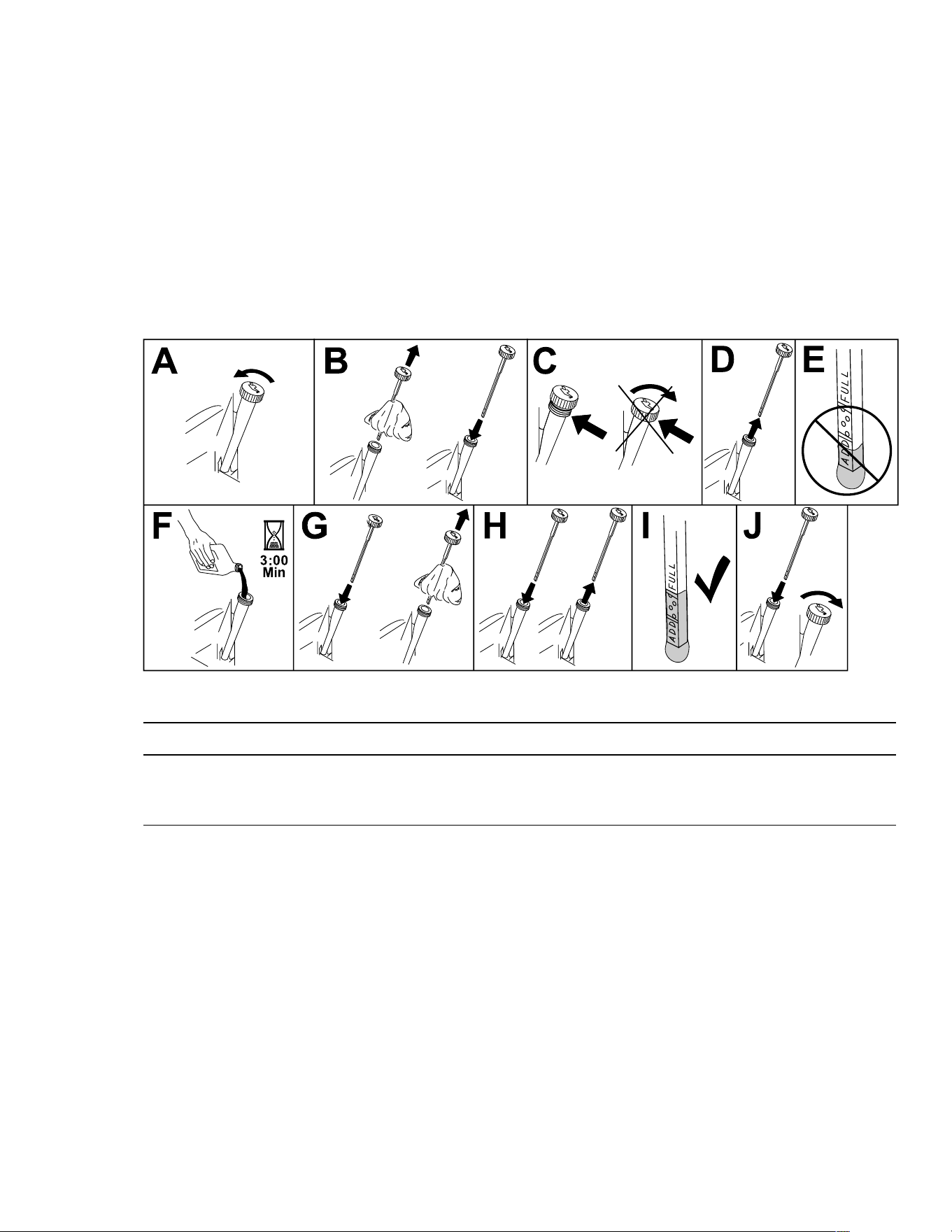
Checking the Engine-Oil Level
1. Park the machine on a level surface, disengage the blade-control switch, and move the
motion-control levers outward to the P
ARK position.
2. Shut off the engine, remove the key, and wait for all moving parts to stop before leaving
the operating position.
3. Wait for the engine to cool so that the oil has had time to drain into the sump.
4. To keep dirt, grass clippings, etc., out of the engine, clean the area around the oil-fill cap
and dipstick before removing it.
5. Check the engine-oil level as shown.
G307458s
IMPORTANT
If you overfill or underfill the engine crankcase with oil and run the engine, you may
damage the engine.
3464-621A Page 5–8 Maintenance: Engine Maintenance
Engine-Oil Service (continued)
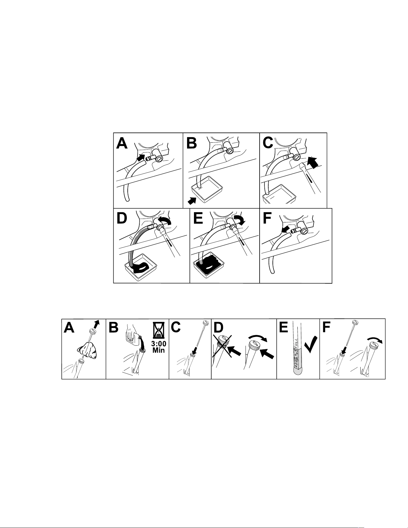
Changing the Engine Oil
1. Park the machine so that the drain side is slightly lower than the opposite side to ensure
that the oil drains completely.
2. Disengage the blade-control switch (PTO) and move the motion-control levers outward
to the P
ARK position.
3. Shut off the engine, remove the key, and wait for all moving parts to stop before leaving
the operating position.
4. Drain the oil from the engine.
G454330
5. Slowly pour approximately 80% of the specified oil into the filler tube and slowly add the
additional oil to bring it to the Full mark.
G235264s
6. Dispose of the used oil at a recycling center.
Maintenance: Engine Maintenance Page 5–9 3464-621 A
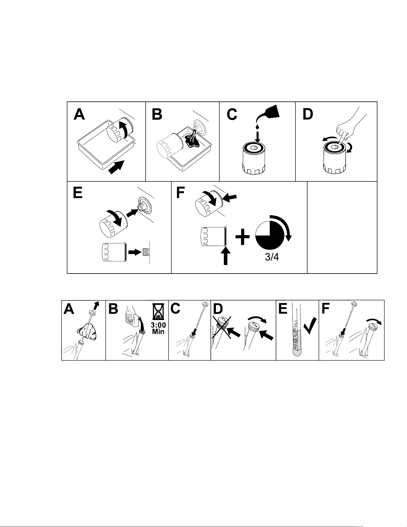
Engine-Oil Service (continued)
Changing the Engine-Oil Filter
1. Drain the oil from the engine.
2. Change the engine-oil filter as shown.
Note: Ensure that the oil-filter gasket touches the engine, and then turn the oil filter an
extra 3/4 turn.
G398545s
3. Slowly add the specified oil into the filler tube to bring the oil level to the Full mark.
G235264s
3464-621A Page 5–10 Maintenance: Engine Maintenance
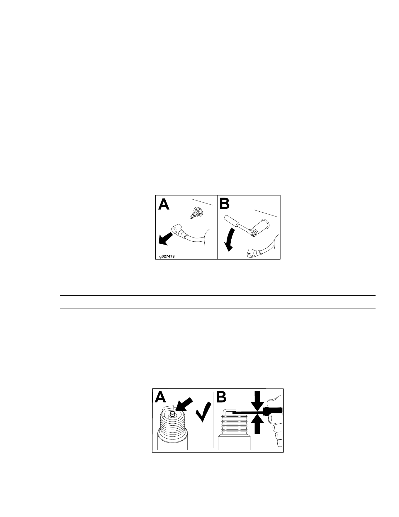
Servicing the Spark Plug
Ensure that the air gap between the center and side electrodes is correct before installing
the spark plug. Use a spark plug wrench for removing and installing the spark plug and a
gapping tool or feeler gauge to check and adjust the air gap. Install a new spark plug if
necessary.
Type: NGK® BPR4ES
Air gap: 0.76 mm (0.03 inch)
Removing the Spark Plug
1. Park the machine on a level surface, disengage the blade-control switch, and move the
motion-control levers outward to the P
ARK position.
2. Shut off the engine, remove the key, and wait for all moving parts to stop before leaving
the operating position.
3. Clean the area around the base of the plug to keep dirt and debris out of the engine.
4. Remove the spark plug.
G437139
Checking the Spark Plug
IMPORTANT
Do not clean the spark plug(s). Always replace the spark plug(s) when it has a black
coating, worn electrodes, an oily film, or cracks.
If you see light brown or gray on the insulator, the engine is operating properly. A black
coating on the insulator usually means the air cleaner is dirty.
Set the gap to 0.75 mm (0.03 inch).
G437150
Maintenance: Engine Maintenance Page 5–11 3464-621 A
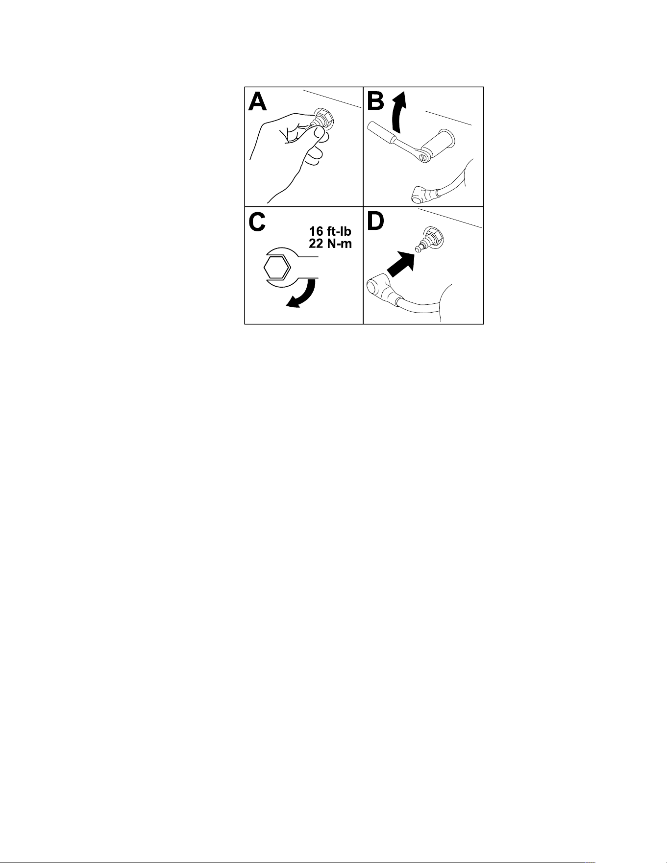
Servicing the Spark Plug (continued)
Installing the Spark Plug
g027661s
Cleaning the Cooling System
1. Park the machine on a level surface, disengage the blade-control switch, and move the
motion-control levers outward to the P
ARK position.
2. Shut off the engine, remove the key, and wait for all moving parts to stop before leaving
the operating position.
3. Remove the air filter from the engine.
4. Remove the engine shroud.
5. To prevent debris entering the air intake, install the air filter to the filter base.
6. Clean debris and grass from the parts.
7. Remove the air filter and install the engine shroud.
8. Install the air filter.
3464-621A Page 5–12 Maintenance: Engine Maintenance
Fuel Maintenance
DANGER
In certain conditions, fuel is extremely flammable and highly explosive. A fire or
explosion from fuel can burn you and others and can damage property.
Refer to Fuel Safety, page 4–2 for a complete list of fuel related precautions.
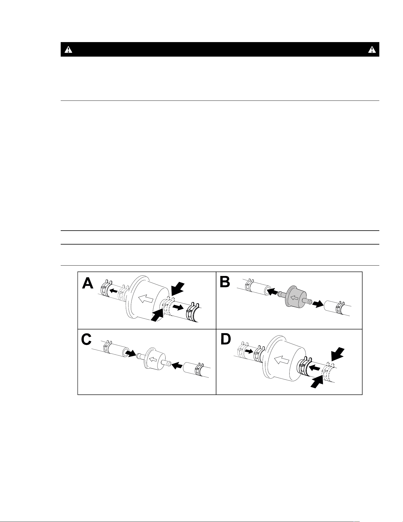
Replacing the Fuel Filter
1. Park the machine on a level surface, disengage the blade-control switch, and move the
motion-control levers outward to the P
ARK position.
2. Shut off the engine, remove the key, and wait for all moving parts to stop before leaving
the operating position.
3. Clamp the fuel lines on both sides of the fuel filter.
4. Replace the filter.
Note: Ensure that the flow-direction arrow on the replacement filter points toward the
engine.
IMPORTANT
Never install a dirty filter after removing it from the fuel line.
G420323
5. Remove the clamps blocking the fuel flow.
Maintenance: Fuel Maintenance Page 5–13 3464-621 A

Electrical System Maintenance
Electrical System Safety
• Disconnect the cable from the negative terminal of the battery before repairing the
machine.
• Charge the battery in an open, well-ventilated area, away from sparks and flames.
Unplug the charger before connecting or disconnecting the battery. Wear protective
clothing and use insulated tools.
Battery Service
Removing the Battery
WARNING
Battery terminals or metal tools could short against metal machine components,
causing sparks. Sparks can cause the battery gasses to explode, resulting in
personal injury.
• When removing or installing the battery, do not allow the battery terminals to
touch any metal parts of the machine.
• Do not allow metal tools to short between the battery terminals and metal parts of
the machine.
1. Park the machine on a level surface, disengage the blade-control switch, and move the
motion-control levers outward to the P
ARK position.
2. Shut off the engine, remove the key, and wait for all moving parts to stop before leaving
the operating position.
3. Disconnect the negative (black) ground cable from the battery post.
Note: Retain all fasteners.
WARNING
Incorrectly removing the cables from battery could damage the machine and cables,
causing sparks. Sparks can cause the battery gasses to explode, resulting in
personal injury.
• Always disconnect the negative (black) battery cable before disconnecting the
positive (red) cable.
• Always connect the positive (red) battery cable before connecting the negative
(black) cable.
4. Slide the rubber cover off the positive (red) cable.
3464-621A Page 5–14 Maintenance: Electrical System Maintenance
Battery Service (continued)
5. Disconnect the positive (red) cable from the battery post (+).
Note: Retain all fasteners.
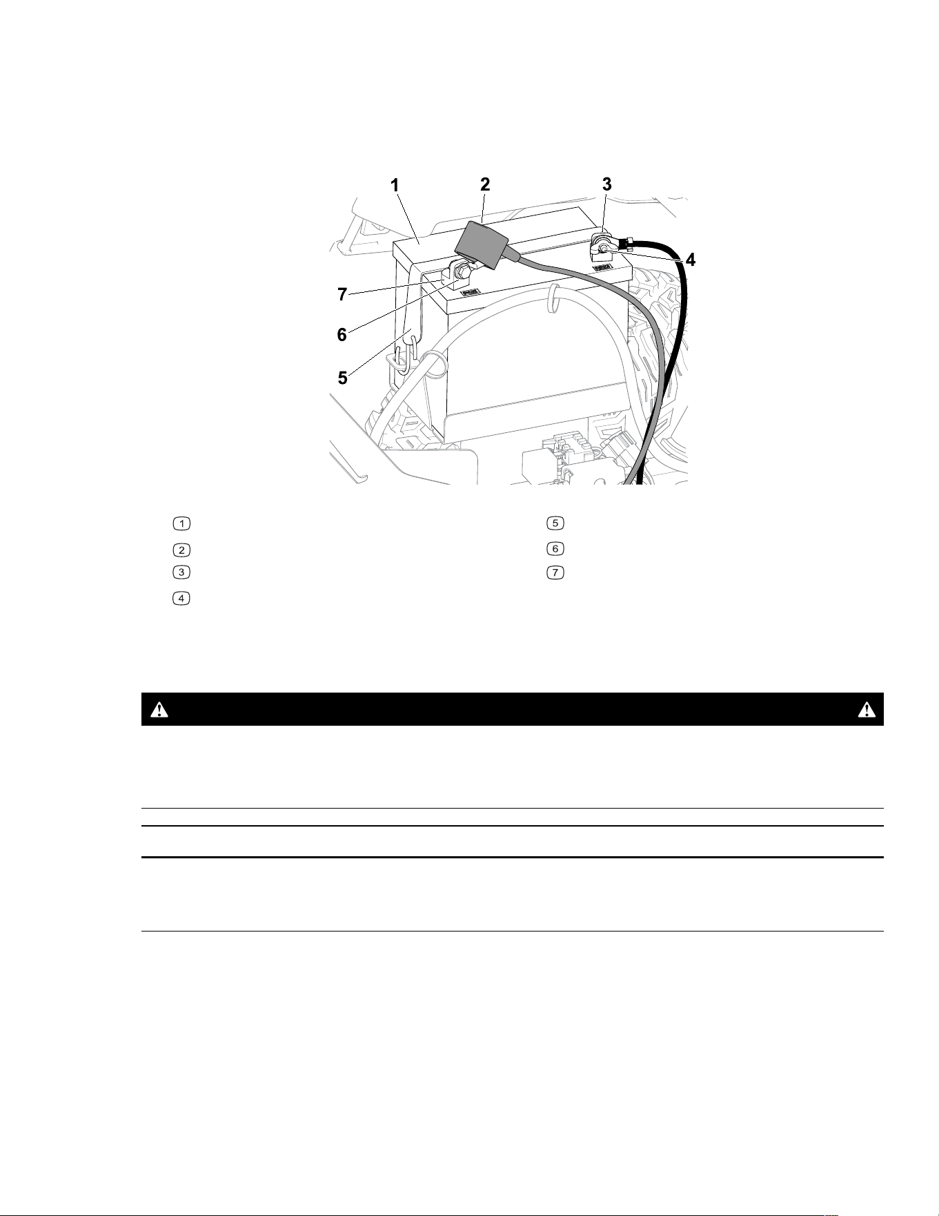
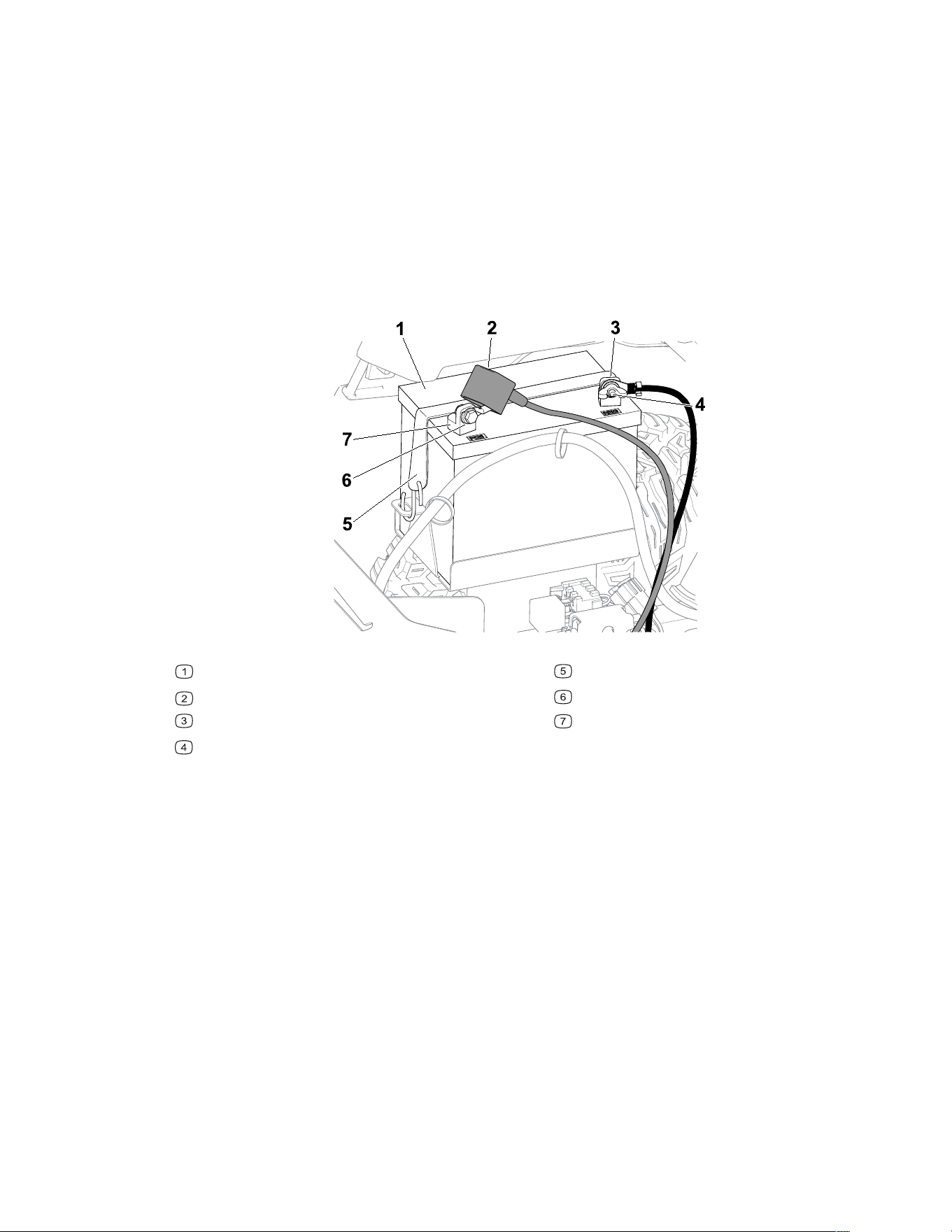
6. Remove the battery hold-down and lift the battery from the battery tray.
G440221
Battery
Terminal boot
Negative (–) battery post
Wing nut, washer, and bolt
Battery hold-down
Bolt, washer, and nut
Positive (+) battery post
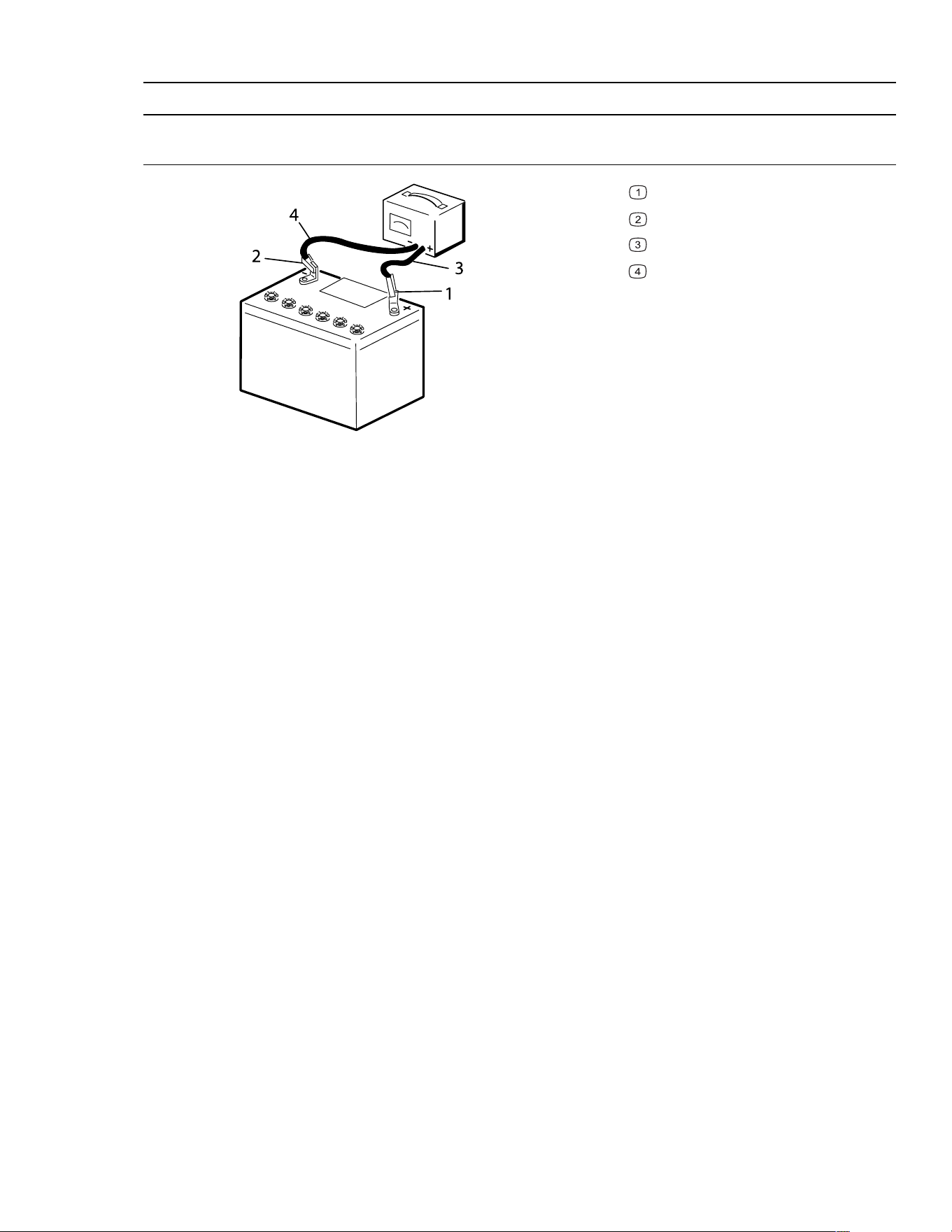
Charging the Battery
WARNING
Charging the battery produces gasses that can explode.
Never smoke near the battery and keep sparks and flames away from battery.
IMPORTANT
Always keep the battery fully charged. This is especially important to prevent battery
damage when the temperature is below 0°C (32°F).
1. Remove the battery from the machine.
2. Charge the battery per the battery charger manufacturer’s instructions.
Maintenance: Electrical System Maintenance Page 5–15 3464-621 A
Battery Service (continued)
IMPORTANT
Do not overcharge the battery; otherwise, you could damage it.
G003792S
Positive battery post
Negative battery post
Red (+) charger lead
Black (-) charger lead
3. When the battery is fully charged, unplug the charger from the electrical outlet (if
applicable), then disconnect the charger leads from the battery posts.
Cleaning the Battery
Note: Keep the terminals and the entire battery case clean, because a dirty battery
discharges slowly.
1. Park the machine on a level surface, disengage the blade-control switch, and move the
motion-control levers outward to the P
ARK position.
2. Shut off the engine and wait for all moving parts to stop before leaving the operating
position.
3. Remove the battery from the machine.
4. Wash the entire case with a solution of baking soda and water.
5. Rinse the battery with clear water.
6. Coat the battery posts and cable connectors with Grafo 112X (skin-over) grease or
petroleum jelly to prevent corrosion.
7. Install the battery.
3464-621A Page 5–16 Maintenance: Electrical System Maintenance
Battery Service (continued)
Installing the Battery
1. Position the battery in the tray.
2. Using the fasteners previously removed, install the positive (red) battery cable to the
positive (+) battery terminal.
3. Using the fasteners previously removed, install the negative battery cable to the
negative (-) battery terminal.
4. Slide the red terminal boot onto the positive (red) battery post.
5. Secure the battery with the hold-down.
G440221
Battery
Terminal boot
Negative (–) battery post
Wing nut, washer, and bolt
Battery hold-down
Bolt, washer, and nut
Positive (+) battery post
Maintenance: Electrical System Maintenance Page 5–17 3464-621 A

Jump-Starting the Machine
WARNING
Jump-starting the battery can produce gasses that can explode.
Do not smoke near the battery, and keep sparks and flames away from battery.
DANGER
Jump-starting a weak battery that is cracked or frozen or has a low electrolyte level or
an open/shorted battery cell can cause an explosion, resulting in serious personal
injury.
Do not jump-start a weak battery if these conditions exist.
1. Check and clean corrosion from the battery terminals before jump-starting. Ensure that
the connections are tight.
CAUTION
Corrosion or loose connections can cause unwanted electrical voltage spikes at any
time during the jump-starting procedure.
Do not attempt to jump-start the machine with loose or corroded battery terminals, or
damage to the engine may occur.
2. Make sure that the booster battery is a good and fully charged lead-acid battery at 12.6
V or greater.
Note: Use properly sized jumper cables with short lengths to reduce voltage drop
between systems. Make sure that the cables are color coded or labeled for the correct
polarity.
WARNING
Batteries contain acid and produce explosive gases.
• Shield your eyes and face from the batteries at all times.
• Do not lean over the batteries.
Note: Ensure that the vent caps are tight and level. Place a damp cloth, if available,
over any vent caps on both batteries. Also ensure that the machines do not touch and
that both electrical systems are off and at the same rated system voltage. These
instructions are for negative ground systems only.
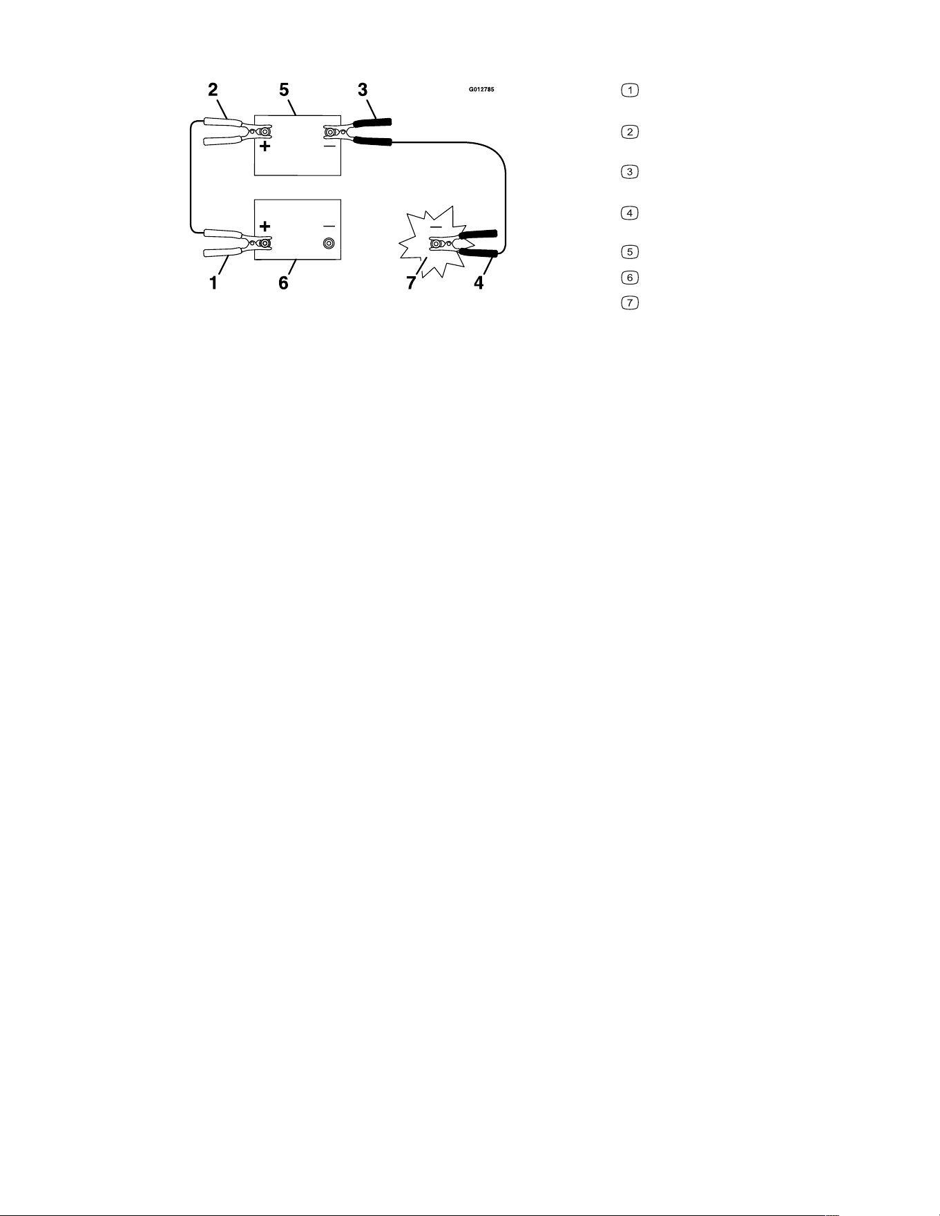
3. Connect the positive (+) cable to the positive (+) terminal of the discharged battery that
is wired to the starter or solenoid as shown:
3464-621A Page 5–18 Maintenance: Electrical System Maintenance
Jump-Starting the Machine (continued)
g012785
Positive (+) cable on discharged
battery
Positive (+) cable on booster
battery
Negative (–) cable on the booster
battery
Negative (–) cable on the engine
block
Booster battery
Discharged battery
Engine block
4. Connect the other end of the positive (+) jumper cable to the positive terminal of the
battery in the other machine.
5. Connect an end of the negative (-) jumper cable to the negative post of the battery in the
other machine.
6. Connect the other end of the negative (-) jumper cable to a ground point, such as an
unpainted bolt or chassis member.
7. Start the engine in the other machine. Let it run a few minutes, then start your engine.
8. Remove the cables in the reverse order of connection.
9. Install the cover to the jump post.
Maintenance: Electrical System Maintenance Page 5–19 3464-621 A
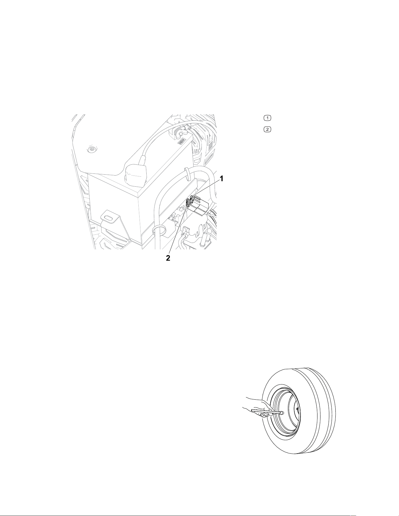
Servicing the Fuses
The electrical system is protected by fuses. It requires no maintenance; however, if a fuse
blows, check the component/circuit for a malfunction or short.
1. Park the machine on a level surface, disengage the blade-control switch, and move the
motion-control levers outward to the P
ARK position.
2. Shut off the engine, remove the key, and wait for all moving parts to stop before leaving
the operating position.
3. Replace the blown fuse with a new fuse.
G440132
Charge circuit (15 A)
Main (25 A)
Drive System Maintenance
Checking the Tire Pressure
Maintain the air pressure in the front and rear tires as specified. Uneven tire pressure can
cause an uneven cut. Check the pressure at the valve stem when the tires are cold to get
the most accurate pressure reading.
G441539
1. Inflate the front caster wheel tires to 206 kPa
(30 psi) or the pressure indicated on the
sidewall, whichever is lower.
2. Inflate the rear drive-wheel tires to 90 kPa (13
psi).
3464-621A Page 5–20 Maintenance: Electrical System Maintenance
Checking the Wheel Lug Nuts
Check and torque the wheel lug nuts to 108 N∙m (80 ft-lb).
Adjusting the Tracking
When driving the machine forward full speed across a flat, level surface, if the machine pulls
to 1 side, adjust the tracking.
If the machine pulls to the left, adjust the right motion-control lever; if the machine pulls to
the right, adjust the left motion-control lever.
Note: You can adjust the tracking only for driving forward.
1. Park the machine on a level surface, disengage the blade-control switch, and move the
motion-control levers outward to the P
ARK position.
2. Shut off the engine, remove the key, and wait for all moving parts to stop before leaving
the operating position.
3. Locate the tracking-adjustment bolt near the motion-control lever on the particular side
that needs adjusting.
G451231
4. Rotate the bolt to decrease the speed for that particular wheel.
Note: Rotate the bolt a small amount to make minor adjustments.
5. Start the machine and drive forward across a flat, level surface with the motion-control
levers fully forward to check if the machine tracks straight. Repeat the procedure as
needed.
Maintenance: Drive System Maintenance Page 5–21 3464-621 A
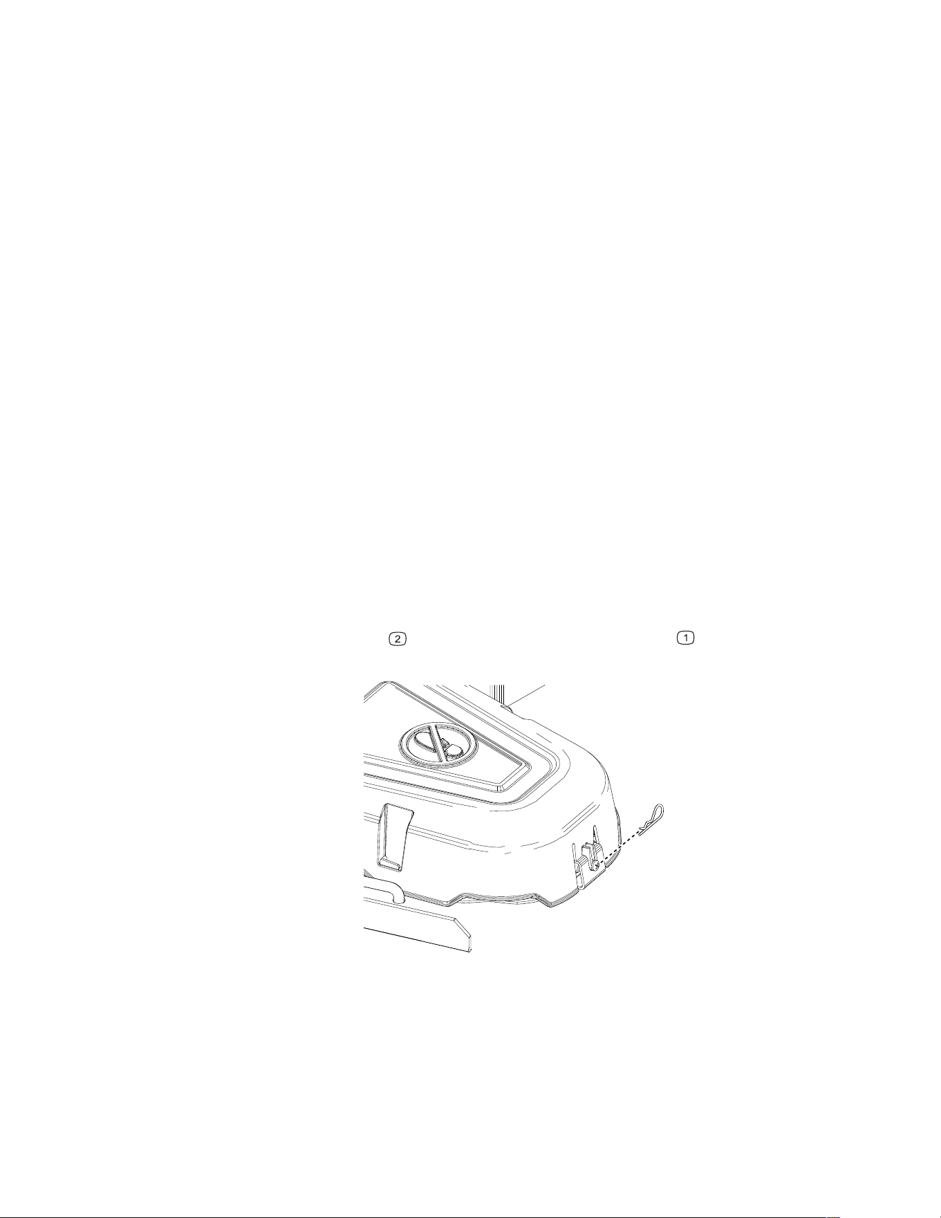
Belt Maintenance
Inspecting the Belts
1. Park the machine on a level surface, disengage the blade-control switch, and move the
motion-control levers outward to the P
ARK position.
2. Shut off the engine and wait for all moving parts to stop before leaving the operating
position.
3. Set the height of cut at the lowest cutting position.
4. Inspect the belt for wear. Replace the belt if it is worn.
The signs of a worn belt include squealing while the belt is rotating; the blades slipping
while cutting grass; and frayed edges, burn marks, and cracks on the belt.
Replacing the Mower Belt
The signs of a worn belt include squealing while the belt is rotating, blades slipping while
cutting grass, and frayed edges, burn marks, and cracks on the belt. Replace the mower belt
if any of these conditions are evident.
1. Park the machine on a level surface, disengage the blade-control switch, and move the
motion-control levers outward to the P
ARK position.
2. Shut off the engine, remove the key, and wait for all moving parts to stop before leaving
the operating position.
3. Set the height of cut at the lowest cutting position.
4. Remove the hairpin cotter
and push in the tab on the cover to remove the pulley
covers.
G451184
5. Loosen the nut securing the wire form to the idler pulley.
3464-621A Page 5–22 Maintenance: Belt Maintenance
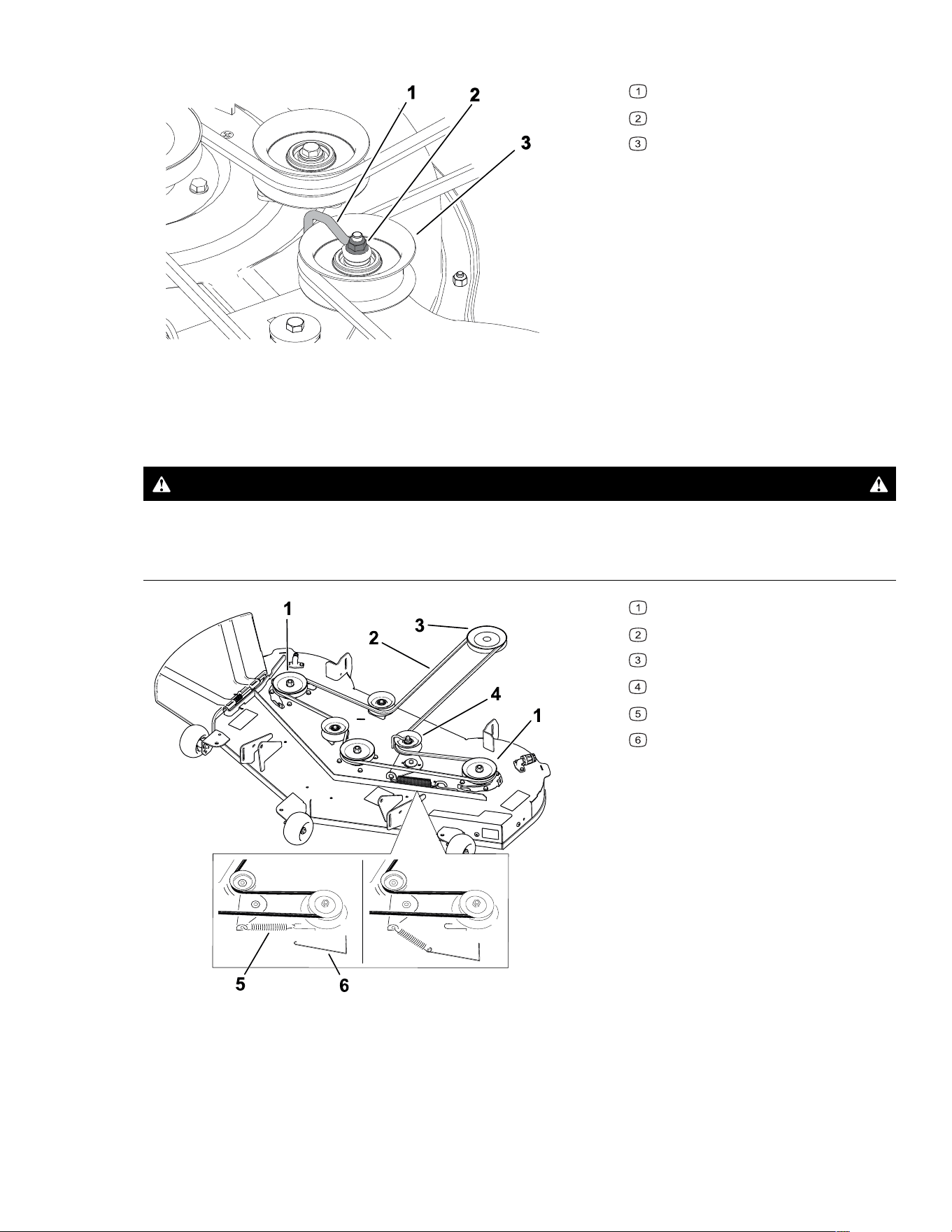
Replacing the Mower Belt (continued)
G336421s
Wire form
Nut
Idler pulley
6. Using a spring-removal too (Toro Part No. 92-5771), remove the idler spring from the
deck hook to remove tension on the idler pulley.
WARNING
The spring is under tension when installed and can cause personal injury.
Be careful when removing the belt.
G454314
Deck pulley
Mower belt
Engine pulley
Idler pulley
Spring
Spring-removal tool
7. Roll the belt off the pulleys.
8. Route the new belt around the engine pulley and mower pulleys.
Maintenance: Belt Maintenance Page 5–23 3464-621 A

Replacing the Mower Belt (continued)
9. Use the spring-removal tool to install the idler spring over the deck hook and place
tension on the idler pulley and the mower belt.
10. Tighten the nut securing the wire form to the idler pulley.
Note: Position the wire form against the idler arm.
11. Install the pulley covers.
Mower-Deck Maintenance
Blade Safety
• Inspect the blades periodically for wear or damage.
• Use care when checking the blades. Wrap the blade(s) or wear gloves and use caution
when servicing them. Only replace damaged blades; never straighten or weld them.
• On multi-bladed machines, take care as rotating one blade can cause other blades to
rotate.
• Replace worn or damaged blades and bolts in sets to preserve balance.
Blade Service
To ensure a superior quality of cut, keep the blades sharp. For convenient sharpening and
replacement, keep extra blades on hand.
Replace the blades if they hit a solid object, or if the blade is out of balance or bent.
Before Inspecting or Servicing the Blades
1. Park the machine on a level surface, disengage the blade-control switch, and move the
motion-control levers outward to the P
ARK position.
2. Shut off the engine, remove the key, and wait for all moving parts to stop before leaving
the operating position.
3. Disconnect the spark-plug wires from the spark plugs.
3464-621A Page 5–24 Maintenance: Mower-Deck Maintenance
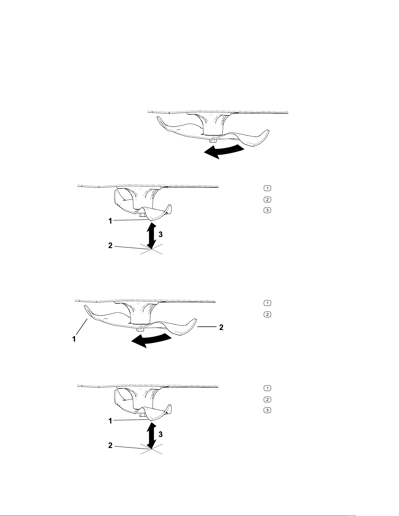
Blade Service (continued)
Checking for Bent Blades
The machine must be on a level surface for this procedure.
1. Raise the mower deck to the highest height-of-cut position.
2. While wearing thickly padded gloves, or other adequate hand protection, slowly rotate
the blade into a position that allows you to measure the distance between the cutting
edge and the level surface.
G451424
3. Measure from the tip of the blade to the level surface.
G451422
Blade (in position for measuring)
Level surface
Measured distance between blade
and the surface (A)
4. Rotate the same blade 180 degrees so that the opposite blade edge is now in the same
position.
G451423
Blade edge previous measured
Opposite blade edge
5. Measure from the tip of the blade to the level surface.
G451422
Blade (in position for measuring)
Level surface
Measured distance between blade
and the surface (B)
Maintenance: Mower-Deck Maintenance Page 5–25 3464-621 A
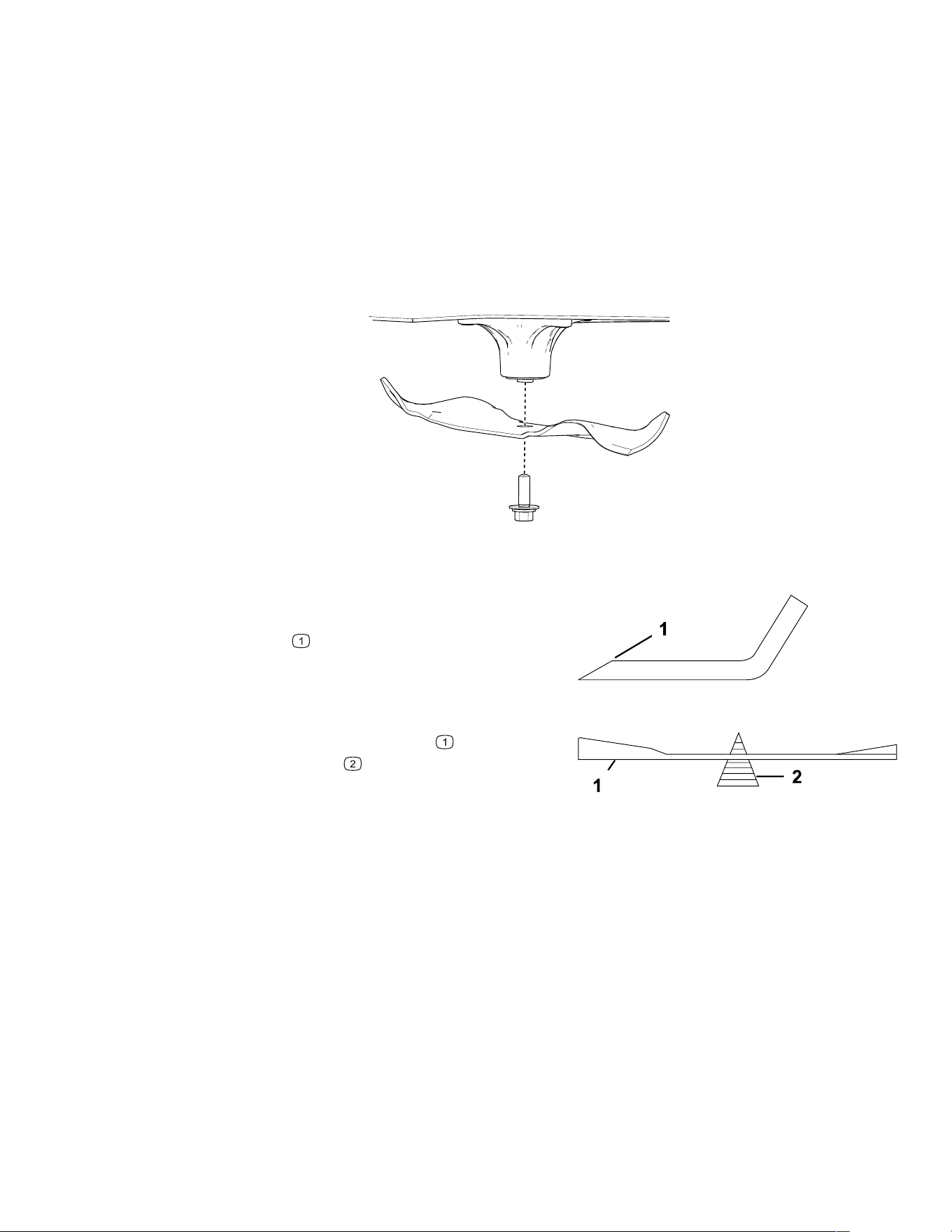
Blade Service (continued)
6. If the difference between A and B is greater than 3 mm (1/8 inch), replace the blade.
Note: If you replace the blade and the difference continues to exceed 3 mm (1/8 inch),
the blade spindle could be bent. Contact an Authorized Service Dealer for service.
7. Repeat this procedure each blade.
Removing the Blades
1. Hold the blade end using a rag or thickly padded glove.
2. Remove the blade as shown.
G451425
Sharpening the Blades
G000552s
1. Use a file to sharpen the cutting edge at both
ends of the blade. Ensure to maintain the
original angle
.
Note: Remove the same amount of material
from both cutting edges so that the blade
retains its balance.
G000553s
2. Check the balance of the blade by putting it
on a blade balancer
.
Note: If the blade stays in a horizontal
position, the blade is balanced and can be
used.
If the blade is not balanced, file some metal off the end of the sail area only.
3. Repeat this procedure until the blade is balanced.
3464-621A Page 5–26 Maintenance: Mower-Deck Maintenance
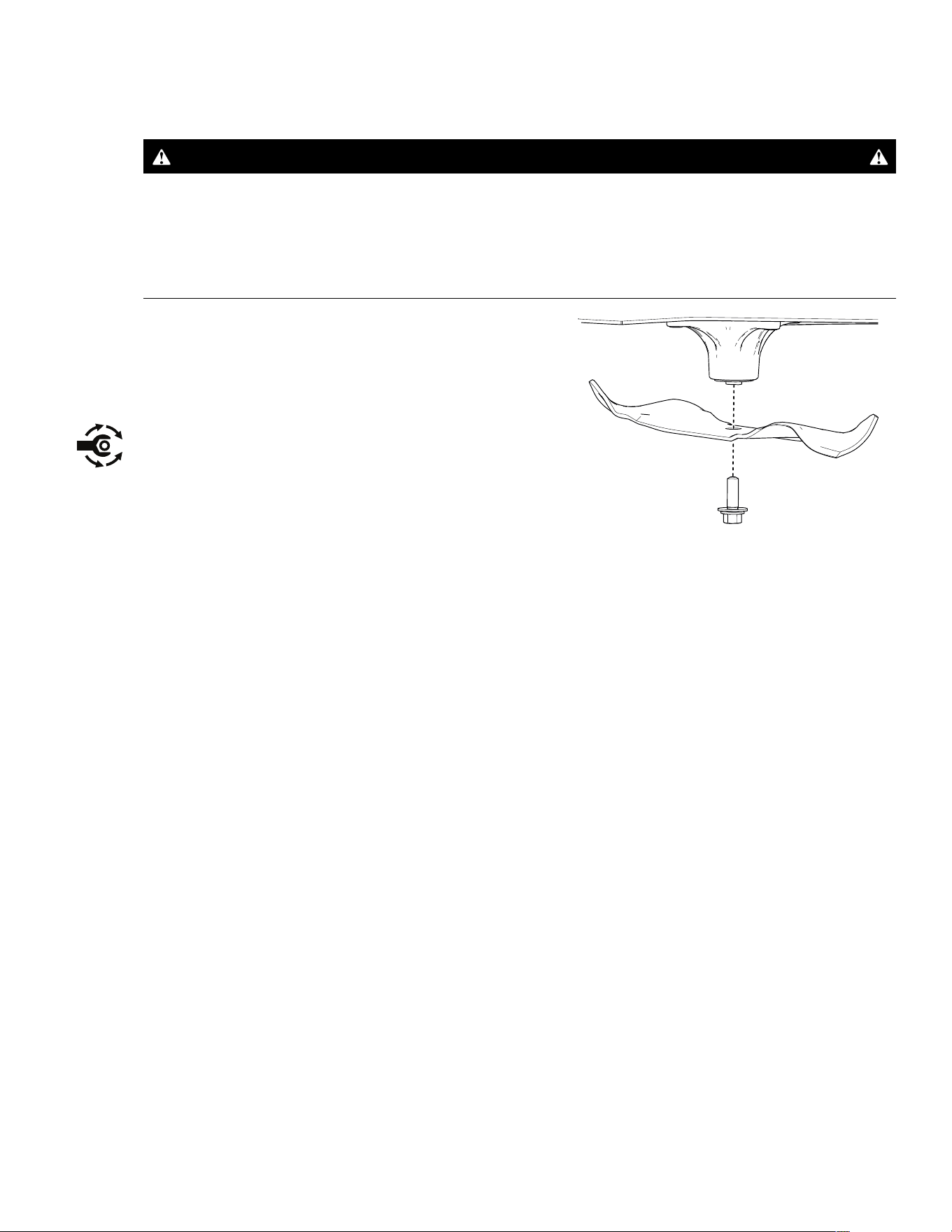
Blade Service (continued)
Installing the Blades
WARNING
Operating a machine after incorrectly installing the blade assembly and/or not using
genuine Toro blade and blade hardware could allow a blade or blade component to be
thrown out from under the deck, resulting in serious injury or death.
Always install genuine Toro blades and blade hardware according to the instructions.
G451425
1. Install the blade as shown.
Note: The curved part of the blade must be
pointing upward toward the inside of the
mower to ensure proper cutting.
2. Torque the blade bolt to 81 to 108 N·m (60 to
80 ft-lb).
Leveling the Mower Deck
Ensure that the mower deck is level any time you install the mower deck or when you see an
uneven cut on your lawn.
Preparing to Level the Mower Deck
1. Park the machine on a level surface, disengage the blade-control switch, and move the
motion-control levers outward to the P
ARK position.
2. Shut off the engine, remove the key, and wait for all moving parts to stop before leaving
the operating position.
3. Ensure that the tires are inflated to the correct specifications and the caster wheels are
facing straight forward.
4. Check the mower deck for bent blades; remove and replace any bent blades.
5. Raise the mower deck to the 76 mm (3 inch) height-of-cut setting.
Maintenance: Mower-Deck Maintenance Page 5–27 3464-621 A
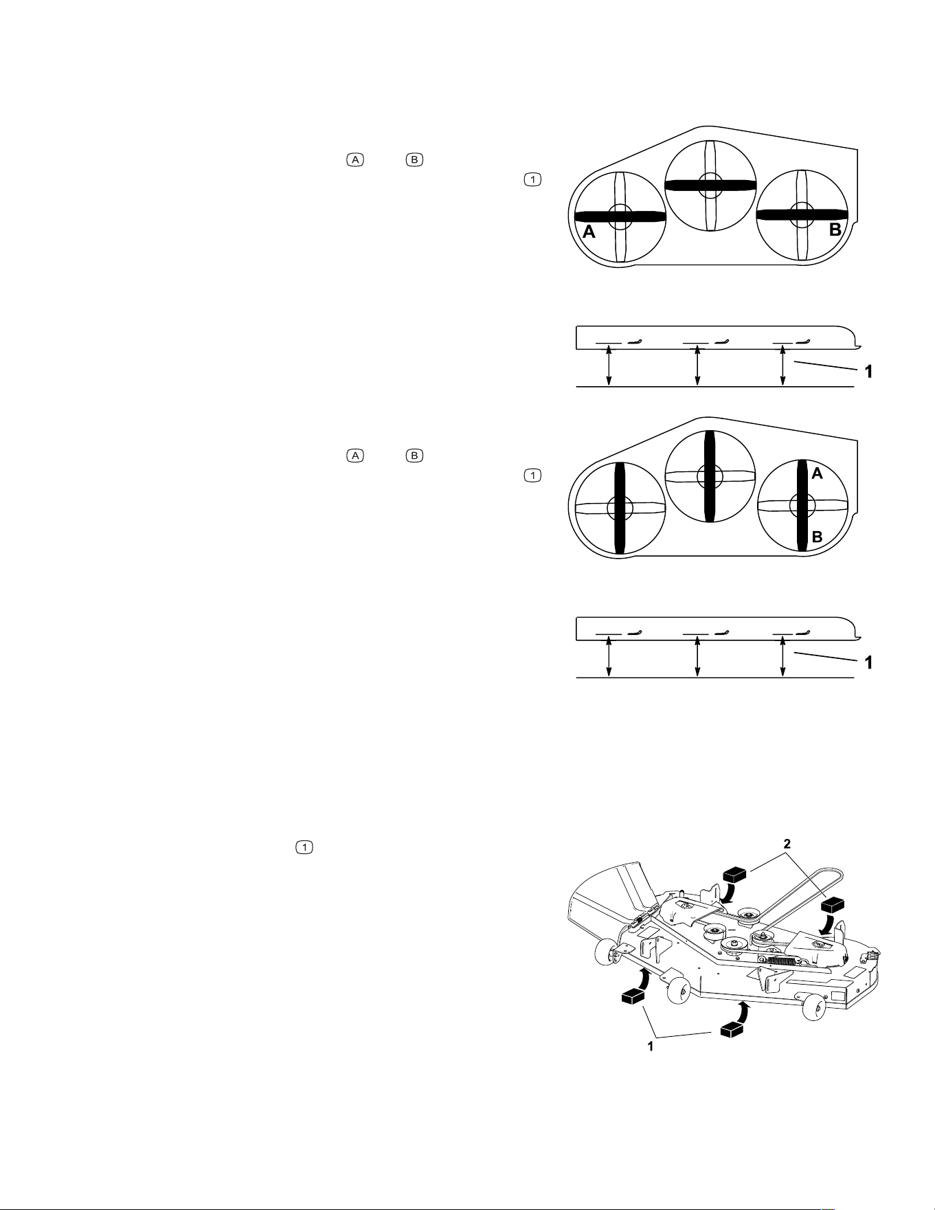
Leveling the Mower Deck (continued)
Checking the Mower-Deck Level
G414698
1. Position the blades side-to-side.
2. Measure at locations
and from a level
surface to the cutting edge of the blade tips
.
The difference between the measurements
should be no more than 5 mm (3/16 inch). If
the measurement is larger, adjust the side-to-
side level.
G414700
3. Position 1 blade front-to-rear.
4. Measure at locations
and from a level
surface to the cutting edge of the blade tips
.
The front blade tip should be 1.6 to 7.9 mm (1/
16 to 5/16 inch) lower than the rear blade tip. If
the measurement is not correct, adjust the
front-to-rear level.
Leveling the Mower Deck
1. Set the anti-scalp rollers to the top holes or remove them completely for this procedure.
2. Set the height-of-cut lever to the 76 mm (3 inch) position.
G454325
3. Place 2 blocks , each having a thickness of
6.6 cm (2-5/8 inches), under each side of the
front edge of the deck.
3464-621A Page 5–28 Maintenance: Mower-Deck Maintenance
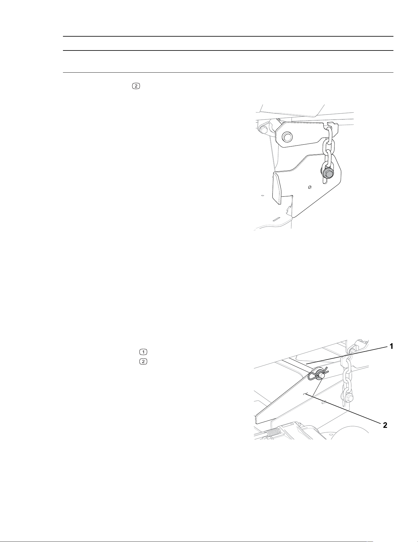
Leveling the Mower Deck (continued)
IMPORTANT
Do not place the blocks under the anti-scalp roller brackets.
4. Place 2 blocks
, each having a thickness of 7.3 cm (2-7/8 inches), under each side of
the rear edge of the deck.
G451475
5. Loosen the fasteners connecting the chains on
all 4 corners of the deck and ensure that the
mower deck sits securely on all 4 blocks.
6. Remove any slack from the deck chains and
ensure that the deck-lift foot lever is pushed
back against the stop.
7. Tighten the fasteners.
8. Ensure that the blocks fit snugly under the
deck edge and that all attachment bolts are
tight.
9. Check the side-to-side level and front-to-rear
level; repeat the procedure until the
measurements are correct.
Removing the Mower Deck
1. Park the machine on a level surface, disengage the blade-control switch, and move the
motion-control levers outward to the P
ARK position.
2. Shut off the engine, remove the key, and wait for all moving parts to stop before leaving
the operating position.
3. Lower the height-of-cut lever to the lowest position.
G451546
4. Remove the hairpin cotter and washer from the
front support rod
, and remove the rod from
the deck bracket
.
Note: Retain all parts for future installation.
5. Lift the deck and chains off the brackets at all 4
corners of the deck.
6. Slide the mower deck rearward to remove the
mower belt from the engine pulley.
7. Slide the mower deck out from underneath the
machine.
Maintenance: Mower-Deck Maintenance Page 5–29 3464-621 A
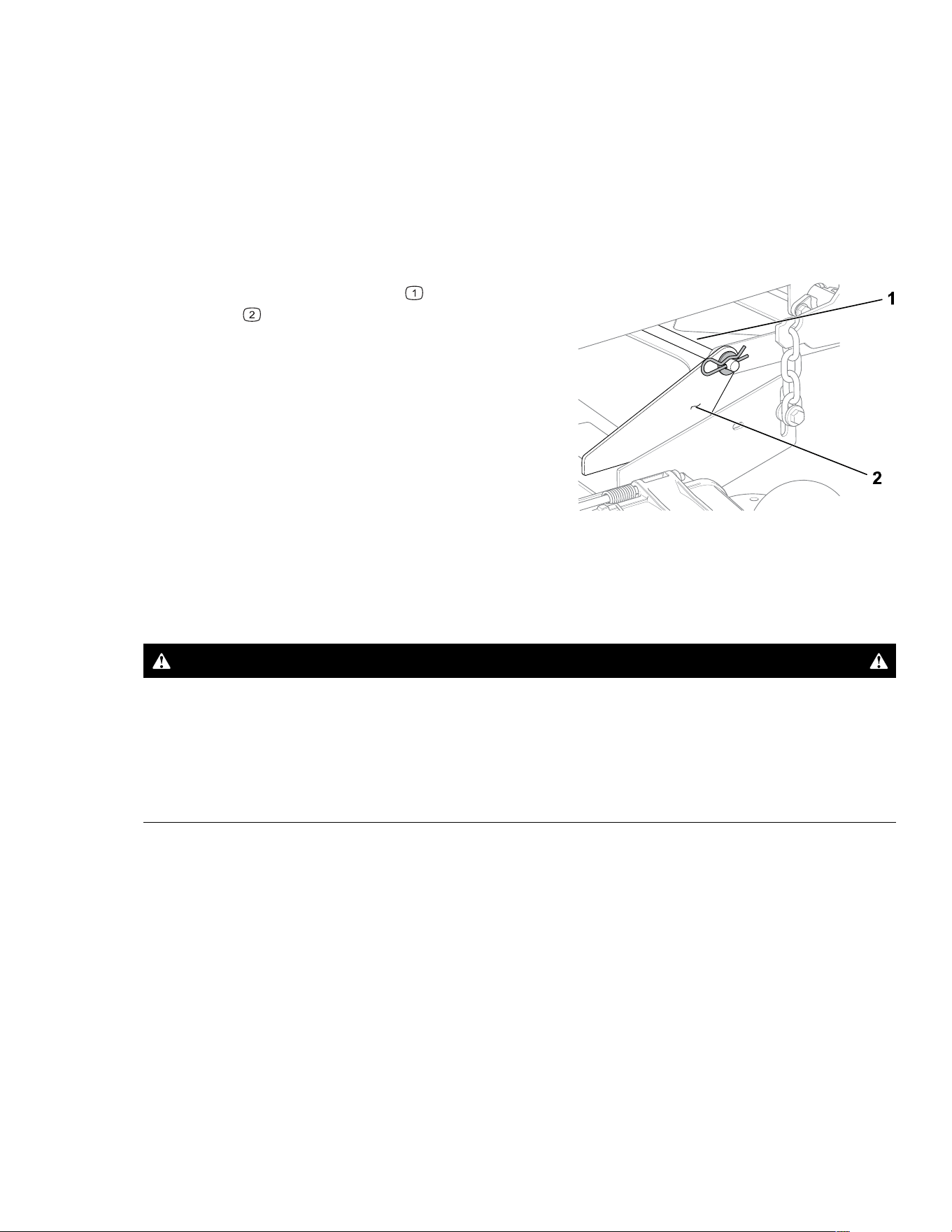
Installing the Mower Deck
1. Park the machine on a level surface, disengage the blade-control switch, and move the
motion-control levers outward to the P
ARK position.
2. Shut off the engine, remove the key, and wait for all moving parts to stop before leaving
the operating position.
3. Slide the mower deck under the machine.
4. Lower the height-of-cut lever to the lowest position.
5. Lift the mower deck chains onto the deck-lift brackets.
G451546
6. Attach the front support rod to the deck
bracket
with the hairpin cotter and washer.
7. Install the mower belt onto the engine pulley.
Replacing the Grass Deflector
DANGER
An uncovered discharge opening allows objects to be thrown toward you or
bystanders. Also, contact with the blade could occur. Thrown objects or blade
contact will cause serious injury or death.
Do not operate the mower with the discharge deflector raised, removed, or altered
unless a grass collection system or mulch kit is in place and working properly.
1. Park the machine on a level surface, disengage the blade-control switch, and move the
motion-control levers outward to the P
ARK position.
2. Shut off the engine, remove the key, and wait for all moving parts to stop before leaving
the operating position.
3. Remove the nut from the rod under the mower deck.
3464-621A Page 5–30 Maintenance: Mower-Deck Maintenance
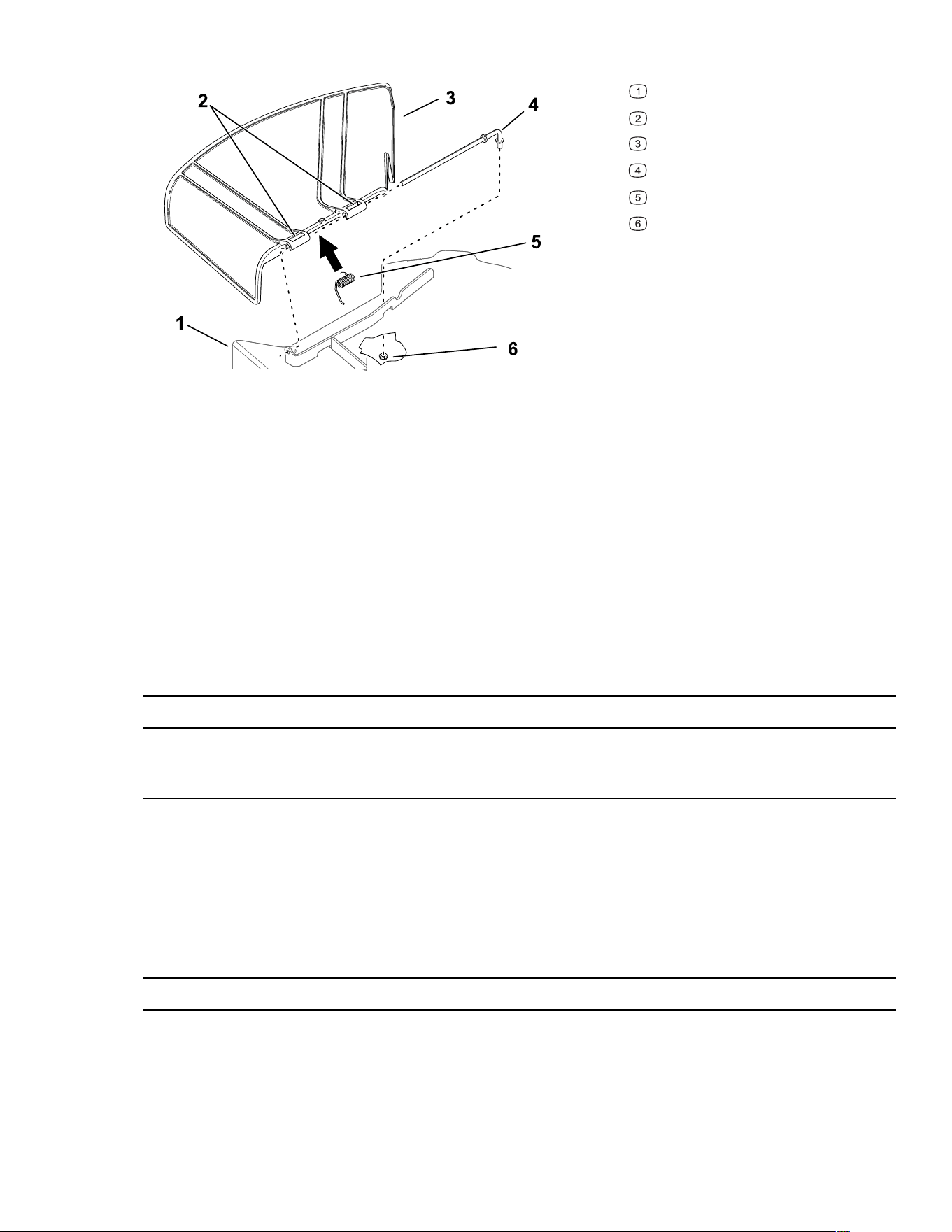
Replacing the Grass Deflector (continued)
G451625
Mower deck
Grass-deflector pivot
Grass deflector
Rod
Spring
Nut
4. Slide the rod out.
5. Remove the damaged or worn grass deflector.
6. Install the new grass deflector.
7. Slide the straight end of the rod through the rear grass deflector pivot.
8. Place the spring on the rod, with end wires down, and between the grass deflector
brackets.
9. Slide the rod through the second grass-deflector pivot.
10. Insert the rod at the front of the grass deflector into the bracket on the deck.
11. Secure the rear end of the rod into the mower with the nut.
IMPORTANT
The grass deflector must be spring-loaded in the down position. Lift the deflector up
to test that it snaps into the full-down position.
Cleaning
Washing the Underside of the Mower Deck
IMPORTANT
You can wash the machine with a mild detergent and water. Do not pressure wash the
machine. Avoid excessive use of water, especially near the control panel, under the
seat, around the engine, hydraulic pumps, and motors.
Maintenance: Cleaning Page 5–31 3464-621 A
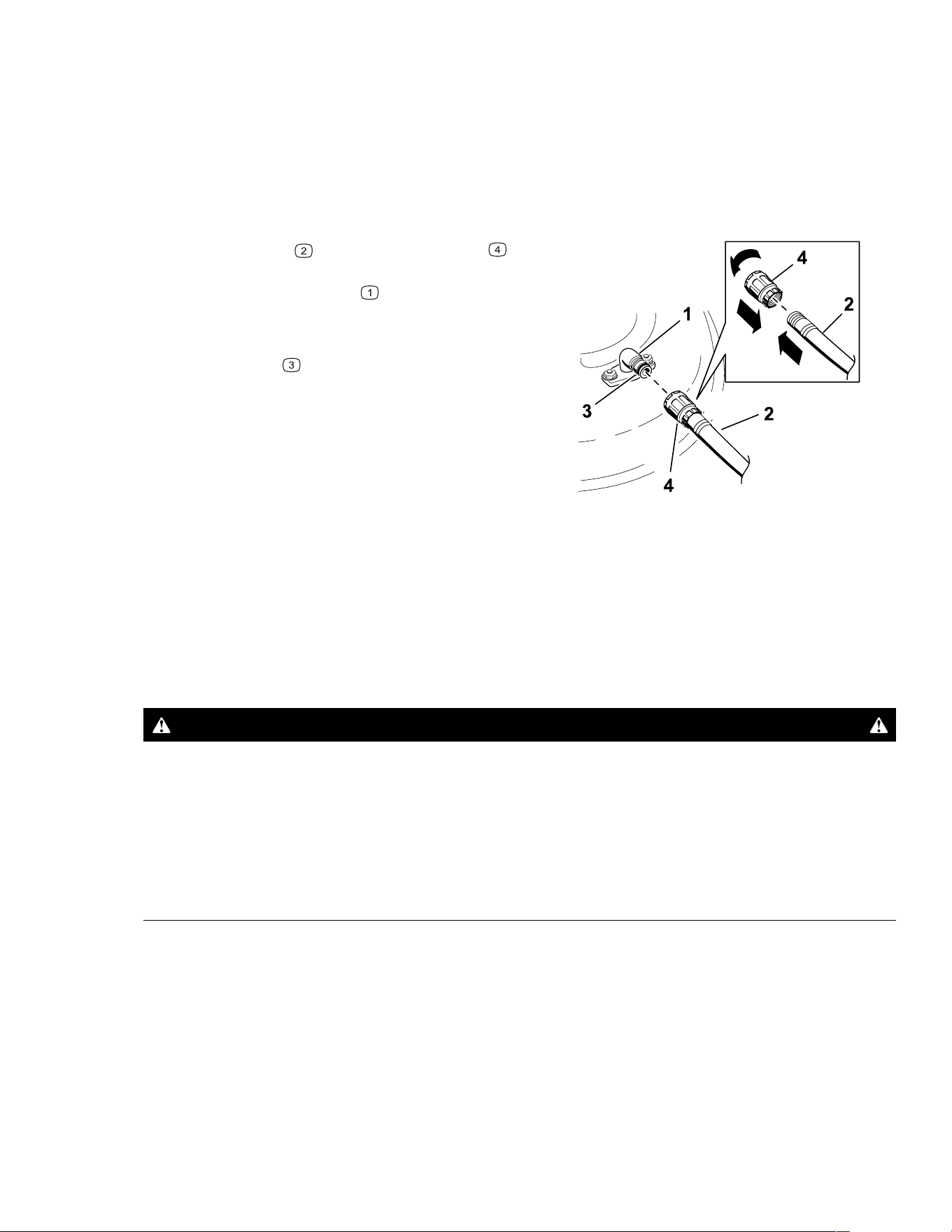
Washing the Underside of the Mower Deck (continued)
Wash the underside of the mower deck after each use to prevent grass buildup for improved
mulch action and clipping dispersal.
1. Park the machine on a level surface, disengage the blade-control switch (PTO), and
move the motion-control levers outward to the P
ARK position.
2. Shut off the engine, remove the key, and wait for all moving parts to stop before leaving
the operating position.
g020098s
3. Attach a hose to the hose coupling , then
attach the hose coupling to the end of the
mower washout fitting
and turn the water on
high.
Note: Spread petroleum jelly on the washout
fitting O-ring
to make the coupling slide on
easier and protect the O-ring.
4. Sit on the seat, lower the mower to the lowest
height-of-cut, and start the engine.
5. Engage the blade-control switch and let the
mower run for 1 to 3 minutes.
6. Disengage the blade-control switch, shut off
the engine, remove the key, and wait for all
moving parts to stop.
7. Turn the water off and remove the coupling from the washout fitting.
Note: If the mower is not clean after 1 washing, soak it and let it stand for 30 minutes.
Then repeat the process.
8. Run the mower again for 1 to 3 minutes to remove excess water.
WARNING
A broken or missing washout fitting could expose you and others to thrown objects
or blade contact. Contact with a blade or thrown debris can cause injury or death.
• Replace broken or missing washout fitting immediately, before using machine
again.
• Never put your hands or feet under the mower or through openings in the
machine.
Disposing of Waste
Engine oil, batteries, hydraulic fluid, and engine coolant are pollutants to the environment.
Dispose of these according to your state and local regulations.
3464-621A Page 5–32 Maintenance: Cleaning

Chapter 6
Storage
Storage Safety
• Park the machine on a level surface, disengage the drives, engage the parking brake,
shut off the engine, remove the key, and wait for all moving parts to stop before leaving
the operator’s position.
• Wait for the machine to cool before servicing, adjusting, fueling, cleaning, or storing it.
• Clean grass and debris from the cutting unit, muffler, drives, grass catcher, and engine
compartment to prevent fires.
• Clean up oil and fuel spills and remove fuel-soaked debris.
• Do not store the machine or fuel container where there is an open flame, spark, or pilot
light, such as on a water heater or other appliance.
Preparing the Machine for Storage Over 30
Days
1. Park the machine on a level surface, disengage the blade-control switch, and move the
motion-control levers outward to the P
ARK position.
2. Shut off the engine, remove the key, and wait for all moving parts to stop before leaving
the operating position.
3. Clean the machine.
IMPORTANT
You can wash the machine with a mild detergent and water. Do not pressure-wash the
machine. Avoid excessive use of water, especially near the drive system and engine.
Pressure-washing can force dirt and water into critical parts, such as spindle
bearings and electrical switches.
A. Remove grass clippings, dirt, and grime from the external parts of the entire
machine, especially the engine.
B. Scrape any heavy buildup of grass and dirt from the underside of the mower, then
wash the machine with a garden hose.
C. Run the machine with the PTO switch engaged and the engine at high idle for 2 to 5
minutes after washing.
4. Check the parking brake operation.
5. Grease the machine.
Storage Page 6–1 3464-621 A

6. Check the tire pressure.
7. Charge the battery.
8. Check the condition of the cutting blades.
9. Prepare the fuel system.
A. Add a petroleum-based fuel stabilizer/conditioner to the fuel in the tank. Do not use
an alcohol-based stabilizer (ethanol or methanol).
B. Run the engine to distribute conditioned fuel through the fuel system for 5 minutes.
C. Shut off the engine, allow it to cool, and drain the fuel tank using a pump-type
syphon or operate the engine until it shuts off.
D. Dispose of fuel properly. Recycle as per local codes.
IMPORTANT
Do not store fuel containing stabilizer/conditioner longer than the duration
recommended by the fuel-stabilizer manufacturer.
10. Prepare the engine.
A. Service the air cleaner.
B. Change the engine oil.
C. Remove the spark plugs and pour 30 ml (2 tablespoons) of engine oil into the spark
plug holes.
D. Place a rag over the spark plug holes to catch any oil spray, then crank the engine
and distribute the oil inside the cylinder.
E. Install the spark plugs, but do not install the wires.
11. Remove the battery or disconnect the negative (-) battery cable.
Note: Store the battery in a cool, dry location, where it will not be exposed to extreme
temperatures or water. Keep the battery fully charged, especially in temperatures below
0°C (32°F).
12. Check and tighten all fasteners. Repair or replace any worn, damaged, or missing parts.
13. Paint all scratched or bare metal surfaces with paint available from your Authorized
Service Dealer.
14. Store the machine in a clean, dry garage or storage area. Cover the machine to protect
it and keep it clean.
3464-621A Page 6–2 Storage: Preparing the Machine for Storage Over 30 Days

Storing the Battery
Note: Follow the tips below to properly store the battery.
• If you are storing the machine for more than 30 days, remove the battery and charge it
fully.
• Store it either on the shelf or on the machine.
• Leave the cables disconnected if they are stored on the machine.
• Store the battery in a cool atmosphere to avoid quick deterioration of the charge in the
battery.
• To prevent the battery from freezing, ensure that it is fully charged.
• The specific gravity of a fully charged battery is 1.265 to 1.299.
Battery Storage Tips
If you are storing the battery outside the machine, do the following:
• Store the battery in a cool, dry area in an upright position.
• Do not stack batteries directly on top of each other, unless they are in cartons.
• Do not stack more than 3 batteries (only 2 if the battery type is commercial).
• Test a wet battery every 4 to 6 months and charge it, if necessary.
• Always test and charge the battery before installation.
Storage: Storing the Battery Page 6–3 3464-621 A

Chapter 7
Troubleshooting
The fuel tank is showing signs of collapsing or the
machine is frequently showing signs of running out of
fuel.
Possible Cause Corrective Action
The air-cleaner paper element clogged. Clean the paper element.
The engine overheats.
Possible Cause Corrective Action
The engine load is excessive. Reduce the ground speed.
The oil level in the crankcase is low. Add oil to the crankcase.
The cooling fins and air passages under the
engine-blower housing are plugged.
Remove the obstruction from the cooling
fins and air passages.
The air cleaner is dirty. Clean or replace the air-cleaner element.
Dirt, water, or stale fuel is in the fuel system. Contact an Authorized Service Dealer.
The starter does not crank.
Possible Cause Corrective Action
The blade-control switch is engaged. Disengage the blade-control switch.
The motion-control levers are not in the
PARK
position.
Move the motion-control levers outward to
the PARK position.
The battery is dead. Charge the battery.
The electrical connections are corroded or
loose.
Check the electrical connections for good
contact.
A fuse is blown. Replace the fuse.
A relay or switch is damaged. Contact an Authorized Service Dealer.
3464-621 A Page 7–1 Troubleshooting

The engine does not start, starts hard, or fails to keep
running.
Possible Cause Corrective Action
The fuel tank is empty. Fill the fuel tank.
The choke (if applicable) is not on. Move the choke lever to the
ON position.
The air cleaner is dirty. Clean or replace the air-cleaner element.
The spark-plug wire(s) is loose or
disconnected.
Install the wire(s) on the spark plug.
The spark plug(s) is pitted, fouled, or the
gap is incorrect.
Install a new, correctly gapped spark plug
(s).
There is dirt in fuel filter. Replace the fuel filter.
Dirt, water, or stale fuel is in fuel system. Contact an Authorized Service Dealer.
There is incorrect fuel in the fuel tank. Drain the tank and replace the fuel with the
proper type.
The oil level in the crankcase is low. Add oil to the crankcase.
The engine loses power.
Possible Cause Corrective Action
The engine load is excessive. Reduce the ground speed.
The air cleaner is dirty. Clean the air-cleaner element.
The oil level in the crankcase is low. Add oil to the crankcase.
The cooling fins and air passages under the
engine blower housing are plugged.
Remove the obstruction from the cooling
fins and air passages.
The spark plug(s) is pitted, fouled, or the
gap is incorrect.
Install a new, correctly gapped spark plug
(s).
The fuel-tank vent is blocked. Contact an Authorized Service Dealer.
There is dirt in the fuel filter. Replace the fuel filter.
Dirt, water, or stale fuel is in the fuel system. Contact an Authorized Service Dealer.
There is incorrect fuel in the fuel tank. Contact an Authorized Service Dealer.
Troubleshooting: Storing the Battery Page 7–2 3464-621 A

The machine does not drive.
Possible Cause Corrective Action
The bypass valves are open. Close the tow valves.
The traction belts are worn, loose, or
broken.
Contact an Authorized Service Dealer.
The traction belts are off the pulleys. Contact an Authorized Service Dealer.
The transmission has failed. Contact an Authorized Service Dealer.
The machine vibrates abnormally.
Possible Cause Corrective Action
The cutting blade(s) is/are bent or
unbalanced.
Install new cutting blade(s).
The blade mounting bolt is loose. Tighten the blade mounting bolt.
The engine mounting bolts are loose. Tighten the engine mounting bolts.
The engine pulley, idler pulley, or blade
pulley is loose.
Tighten the appropriate pulley.
The engine pulley is damaged. Contact an Authorized Service Dealer.
The blade spindle is bent. Contact an Authorized Service Dealer.
The motor mount is loose or worn. Contact an Authorized Service Dealer.
The cutting height is uneven.
Possible Cause Corrective Action
The blade(s) is not sharp. Sharpen the blade(s).
A cutting blade(s) is/are bent. Install a new cutting blade(s).
The mower is not level. Level the mower from side-to-side and
front-to-rear.
An anti-scalp roller (if applicable) is not set
correctly.
Adjust the anti-scalp wheel height.
The underside of the mower deck is dirty. Clean the underside of the mower deck.
The tire pressure is incorrect. Adjust the tire pressure.
A blade spindle is bent. Contact an Authorized Service Dealer.
3464-621A Page 7–3 Troubleshooting: Storing the Battery

The blades do not rotate.
Possible Cause Corrective Action
The drive belt is worn, loose or broken. Install a new drive belt.
The drive belt is off of the pulley. Install the drive belt and check the adjusting
shafts and belt guides for the correct
position.
The power-takeoff (PTO) switch or PTO
clutch is faulty.
Contact an Authorized Service Dealer.
The mower belt is worn, loose, or broken. Install a new mower belt.
Troubleshooting: Storing the Battery Page 7–4 3464-621 A
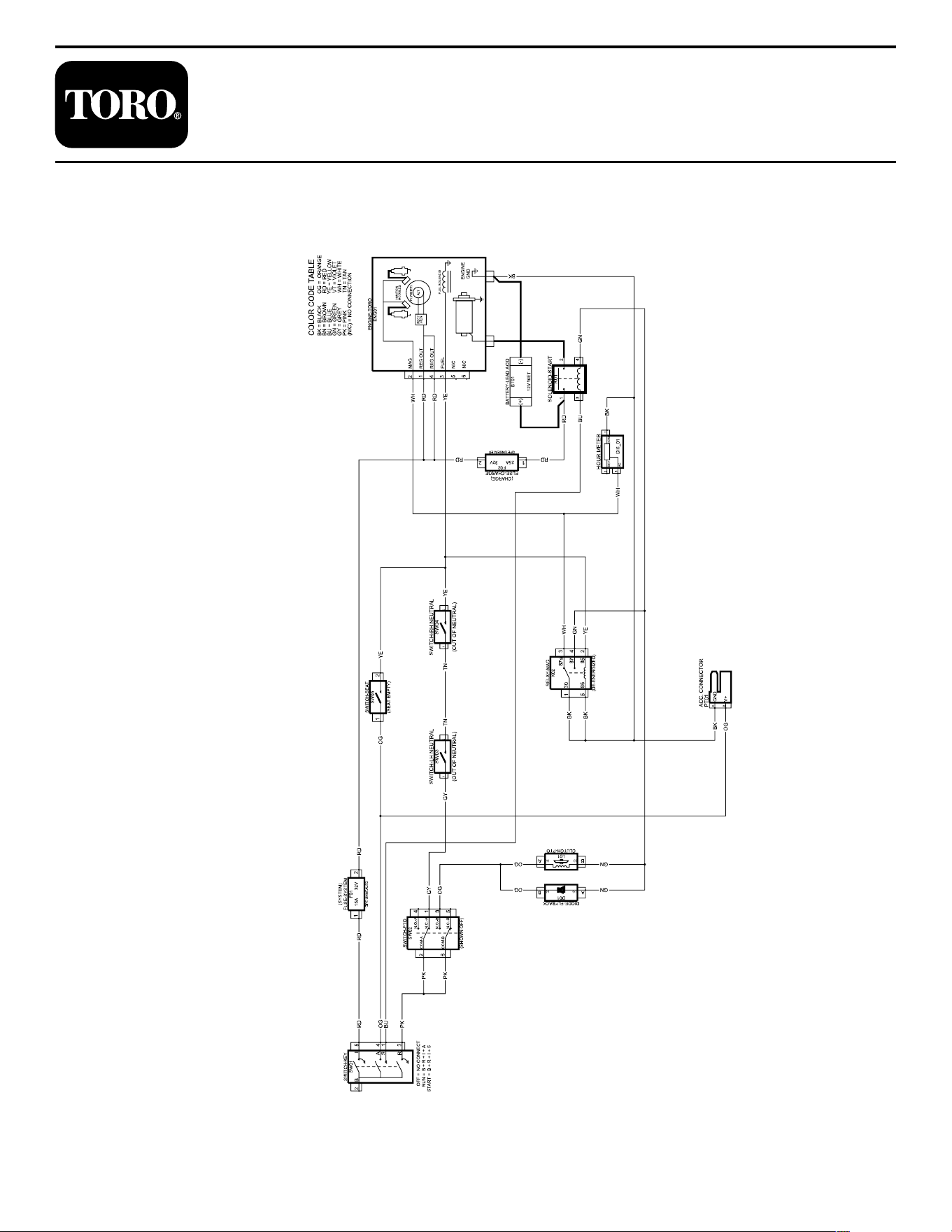

California Proposition 65 Warning Information
What is this warning?
You may see a product for sale that has a warning label like the following:
WARNING: Cancer and Reproductive Harm—www.p65Warnings.ca.gov.
What is Prop 65?
Prop 65 applies to any company operating in California, selling products in California, or manufacturing products that may
be sold in or brought into California. It mandates that the Governor of California maintain and publish a list of chemicals
known to cause cancer, birth defects, and/or other reproductive harm. The list, which is updated annually, includes
hundreds of chemicals found in many everyday items. The purpose of Prop 65 is to inform the public about exposure to
these chemicals.
Prop 65 does not ban the sale of products containing these chemicals but instead requires warnings on any product,
product packaging, or literature with the product. Moreover, a Prop 65 warning does not mean that a product is in violation
of any product safety standards or requirements. In fact, the California government has clarified that a Prop 65 warning “is
not the same as a regulatory decision that a product is ‘safe’ or ‘unsafe.’” Many of these chemicals have been used in
everyday products for years without documented harm. For more information, go to https://oag.ca.gov/prop65/faqs-view-all.
A Prop 65 warning means that a company has either (1) evaluated the exposure and has concluded that it exceeds the “no
significant risk level”; or (2) has chosen to provide a warning based on its understanding about the presence of a listed
chemical without attempting to evaluate the exposure.
Does this law apply everywhere?
Prop 65 warnings are required under California law only. These warnings are seen throughout California in a wide range of
settings, including but not limited to restaurants, grocery stores, hotels, schools, and hospitals, and on a wide variety of
products. Additionally, some online and mail order retailers provide Prop 65 warnings on their websites or in catalogs.
How do the California warnings compare to federal limits?
Prop 65 standards are often more stringent than federal and international standards. There are various substances that
require a Prop 65 warning at levels that are far lower than federal action limits. For example, the Prop 65 standard for
warnings for lead is 0.5 μg/day, which is well below the federal and international standards.
Why don’t all similar products carry the warning?
• Products sold in California require Prop 65 labelling while similar products sold elsewhere do not.
• A company involved in a Prop 65 lawsuit reaching a settlement may be required to use Prop 65 warnings for its
products, but other companies making similar products may have no such requirement.
• The enforcement of Prop 65 is inconsistent.
• Companies may elect not to provide warnings because they conclude that they are not required to do so under Prop 65;
a lack of warnings for a product does not mean that the product is free of listed chemicals at similar levels.
Why does Toro include this warning?
Toro has chosen to provide consumers with as much information as possible so that they can make informed decisions
about the products they buy and use. Toro provides warnings in certain cases based on its knowledge of the presence of
one or more listed chemicals without evaluating the level of exposure, as not all the listed chemicals provide exposure limit
requirements. While the exposure from Toro products may be negligible or well within the “no significant risk” range, out of
an abundance of caution, Toro has elected to provide the Prop 65 warnings. Moreover, if Toro does not provide these
warnings, it could be sued by the State of California or by private parties seeking to enforce Prop 65 and subject to
substantial penalties.

Notes: