

FormNo.3456-108RevA
TimeCutter
®
MyRIDE
®
42in,50in,
or54inRidingMower
ModelNo.75747—SerialNo.412562015andUp
ModelNo.75747TA—SerialNo.400000000andUp
ModelNo.75747W—SerialNo.412090000andUp
ModelNo.75756—SerialNo.412515219andUp
ModelNo.75758TA—SerialNo.412540000andUp
ModelNo.75761TA—SerialNo.412600000andUp
Registeratwww.Toro.com.
OriginalInstructions(EN)
*3456-108*
ItisaviolationofCaliforniaPublicResourceCode
Section4442or4443touseoroperatetheengineon
anyforest-covered,brush-covered,orgrass-covered
landunlesstheengineisequippedwithaspark
arrester,asdenedinSection4442,maintainedin
effectiveworkingorderortheengineisconstructed,
equipped,andmaintainedforthepreventionofre.
GrossorNetTorque:Thegrossornettorque
ofthisenginewaslaboratoryratedbytheengine
manufacturerinaccordancewiththeSocietyof
AutomotiveEngineers(SAE)J1940orJ2723.As
conguredtomeetsafety,emission,andoperating
requirements,theactualenginetorqueonthisclass
ofmowerwillbesignicantlylower.Pleasereferto
theenginemanufacturer’sinformationincludedwith
themachine.
Theenclosedengineowner'smanualissupplied
forinformationregardingtheUSEnvironmental
ProtectionAgency(EPA)andtheCaliforniaEmission
ControlRegulationofemissionsystems,maintenance,
andwarranty.Replacementsmaybeorderedthrough
theenginemanufacturer.
WARNING
CALIFORNIA
Proposition65Warning
Theengineexhaustfromthisproduct
containschemicalsknowntotheStateof
Californiatocausecancer,birthdefects,
orotherreproductiveharm.
Batteryposts,terminals,andrelated
accessoriescontainleadandlead
compounds,chemicalsknownto
theStateofCaliforniatocause
cancerandreproductiveharm.Wash
handsafterhandling.
Useofthisproductmaycauseexposure
tochemicalsknowntotheStateof
Californiatocausecancer,birthdefects,
orotherreproductiveharm.
Introduction
Thisrotary-blade,ridinglawnmowerisintendedtobe
usedbyhomeownersinresidentialapplications.Itis
designedprimarilyforcuttinggrassonwell-maintained
lawns.Usingthisproductforpurposesotherthan
itsintendedusecouldprovedangeroustoyouand
bystanders.
Readthisinformationcarefullytolearnhowtooperate
andmaintainyourproductproperlyandtoavoid
injuryandproductdamage.Youareresponsiblefor
operatingtheproductproperlyandsafely.
Visitwww.Toro.comforproductsafetyandoperation
trainingmaterials,accessoryinformation,helpnding
adealer,ortoregisteryourproduct.
Wheneveryouneedservice,genuineToroparts,or
additionalinformation,contactanAuthorizedService
DealerorT oroCustomerServiceandhavethemodel
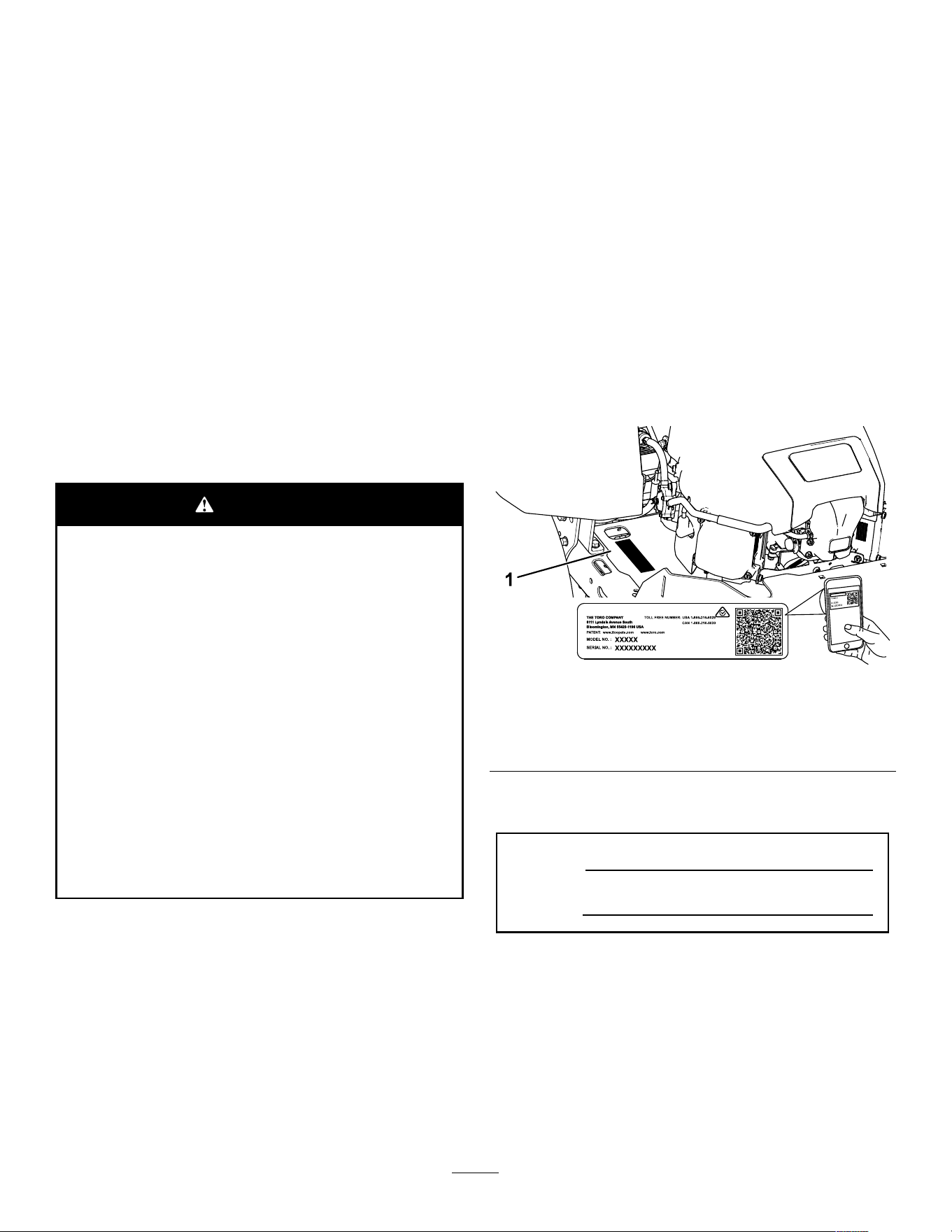
andserialnumbersofyourproductready.Figure1
identiesthelocationofthemodelandserialnumbers
ontheproduct.Writethenumbersinthespace
provided.
Important:Withyourmobiledevice,youcan
scantheQRcodeontheserialnumberdecal(if
equipped)toaccesswarranty,parts,andother
productinformation.
g297763
Figure1
Undertheseat
1.Modelandserialnumberlocation
Writetheproductmodelandserialnumbersinthe
spacebelow:
ModelNo.
SerialNo.
Thismanualuses2wordstohighlightinformation.
Importantcallsattentiontospecialmechanical
informationandNoteemphasizesgeneralinformation
worthyofspecialattention.
Thesafety-alertsymbol(Figure2)appearsbothin
thismanualandonthemachinetoidentifyimportant
safetymessagesthatyoumustfollowtoavoid
accidents.Thissymbolwillappearwiththeword
Danger,Warning,orCaution.
©2022—TheToro®Company
8111LyndaleAvenueSouth
Bloomington,MN55420
2
Contactusatwww.Toro.com.
PrintedintheUSA
AllRightsReserved

•Dangerindicatesanimminentlyhazardous
situationwhich,ifnotavoided,willresultindeath
orseriousinjury.
•Warningindicatesapotentiallyhazardous
situationwhich,ifnotavoided,couldresultin
deathorseriousinjury.
•Cautionindicatesapotentiallyhazardoussituation
which,ifnotavoided,mayresultinminoror
moderateinjury.
sa-black
Figure2
1.Safety-alertsymbol
Contents
Safety.......................................................................4
GeneralSafety...................................................4
SlopeIndicator...................................................5
SafetyandInstructionalDecals..........................6
ProductOverview....................................................11
Controls...........................................................12
Specications..................................................13
Attachments/Accessories.................................13
BeforeOperation.................................................13
BeforeOperationSafety...................................13
AddingFuel......................................................14
PerformingDailyMaintenance..........................15
BreakinginaNewMachine..............................15
UsingtheSafety-InterlockSystem....................15
PositioningtheSeat..........................................16
AdjustingtheMyRide®Suspension
System..........................................................16
AdjustingtheMotion-ControlLevers.................16
DuringOperation.................................................17
DuringOperationSafety...................................17
OperatingtheMowerBlade-ControlSwitch
(PTO)............................................................19
OperatingtheThrottle.......................................20
OperatingtheChoke.........................................20
StartingtheEngine...........................................20
ShuttingOfftheEngine.....................................21
UsingtheMotion-ControlLevers.......................21
DrivingtheMachine..........................................21
UsingtheSmartSpeed
TM
Control
System..........................................................22
UsingtheSideDischarge.................................23
AdjustingtheHeightofCut...............................23
AdjustingtheAnti-ScalpRollers........................24
OperatingTips.................................................25
AfterOperation....................................................26
AfterOperationSafety......................................26
CleaningtheMachine.......................................26
PushingtheMachinebyHand..........................26
TransportingtheMachine.................................27
Maintenance...........................................................29
MaintenanceSafety..........................................29
RecommendedMaintenanceSchedule(s)...........30
Pre-MaintenanceProcedures..............................30
RaisingtheMachine.........................................30
Lubrication..........................................................31
GreasingtheBearings......................................31
EngineMaintenance...........................................32
EngineSafety...................................................32
ServicingtheAirCleaner..................................32
ServicingtheEngineOil....................................33
ServicingtheSparkPlug...................................35
CleaningtheBlowerHousing............................36
FuelSystemMaintenance...................................36
ReplacingtheIn-LineFuelFilter.......................36
ElectricalSystemMaintenance...........................37
ElectricalSystemSafety...................................37
ServicingtheBattery.........................................37
ServicingtheFuses..........................................39
DriveSystemMaintenance..................................39
CheckingtheTirePressure...............................39
ReleasingtheElectricBrake.............................40
AdjustingtheTracking......................................40
BeltMaintenance................................................41
InspectingtheBelts..........................................41
ReplacingtheMowerBelt.................................41
MowerMaintenance.............................................42
BladeSafety.....................................................42
ServicingtheCuttingBlades.............................42
LevelingtheMowerDeck..................................45
RemovingtheMowerDeck...............................48
InstallingtheMowerDeck.................................48
ReplacingtheGrassDeector..........................49
Cleaning..............................................................50
WashingtheUndersideoftheMower
Deck..............................................................50
DisposingofWaste...........................................50
Storage...................................................................51
StorageSafety..................................................51
CleaningandStorage.......................................51
StoringtheBattery............................................52
Troubleshooting......................................................53
Schematics.............................................................55
3

Safety
Thismachinehasbeendesignedinaccordancewith
ANSIB71.1-2017.
GeneralSafety
Thisproductiscapableofamputatinghandsand
feetandofthrowingobjects.Alwaysfollowallsafety
instructionstoavoidseriouspersonalinjuryordeath.
•Readandunderstandthecontentsofthis
Operator’sManualbeforestartingtheengine.
•Keepbystandersandchildrenaway.
•Donotallowchildrenoruntrainedpeopleto
operateorservicethemachine.Allowonlypeople
whoareresponsible,trained,familiarwiththe
instructions,andphysicallycapabletooperateor
servicethemachine.
•Donotoperatethemachineneardrop-offs,
ditches,embankments,water,orotherhazards,or
onslopesgreaterthan15°.
•Donotputyourhandsorfeetnearmoving
componentsofthemachine.
•Donotoperatethemachinewithoutallguards,
safetyswitches,andothersafetyprotective
devicesinplaceandfunctioningproperly.
•Shutofftheengine,removethekey,andwait
forallmovingpartstostopbeforeleavingthe
operator’sposition.Allowthemachinetocool
beforeservicing,adjusting,fueling,cleaning,or
storingit.
4
SlopeIndicator
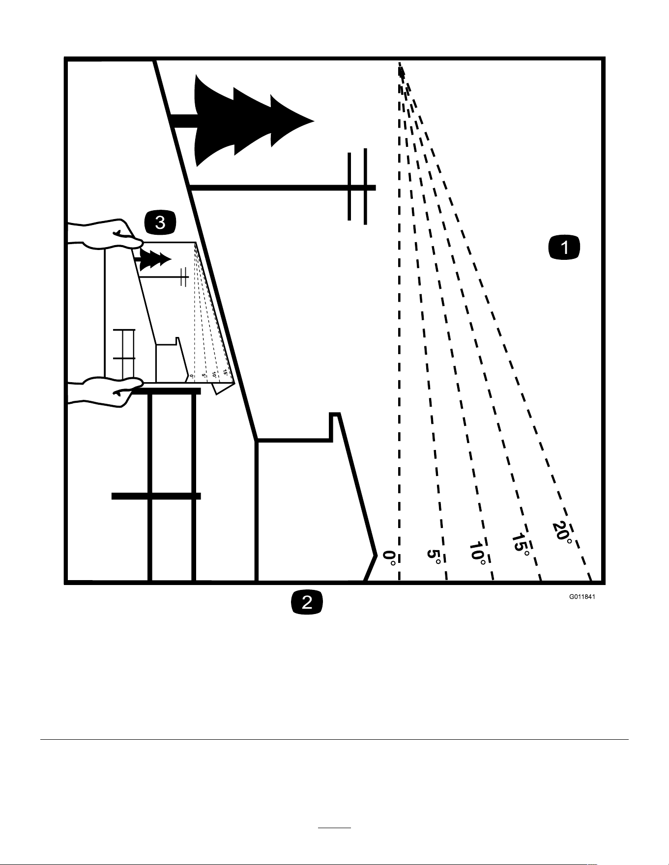
g011841
Figure3
Youmaycopythispageforpersonaluse.
1.Themaximumslopeyoucanoperatethemachineonis15degrees.Usetheslopecharttodeterminethedegreeofslopeof
hillsbeforeoperating.Donotoperatethismachineonaslopegreaterthan15degrees.Foldalongtheappropriateline
tomatchtherecommendedslope.
2.Alignthisedgewithaverticalsurface,atree,building,fencepole,etc.
3.Exampleofhowtocompareslopewithfoldededge
5
SafetyandInstructionalDecals
Safetydecalsandinstructionsareeasilyvisibletotheoperatorandarelocatednearanyarea
ofpotentialdanger.Replaceanydecalthatisdamagedormissing.
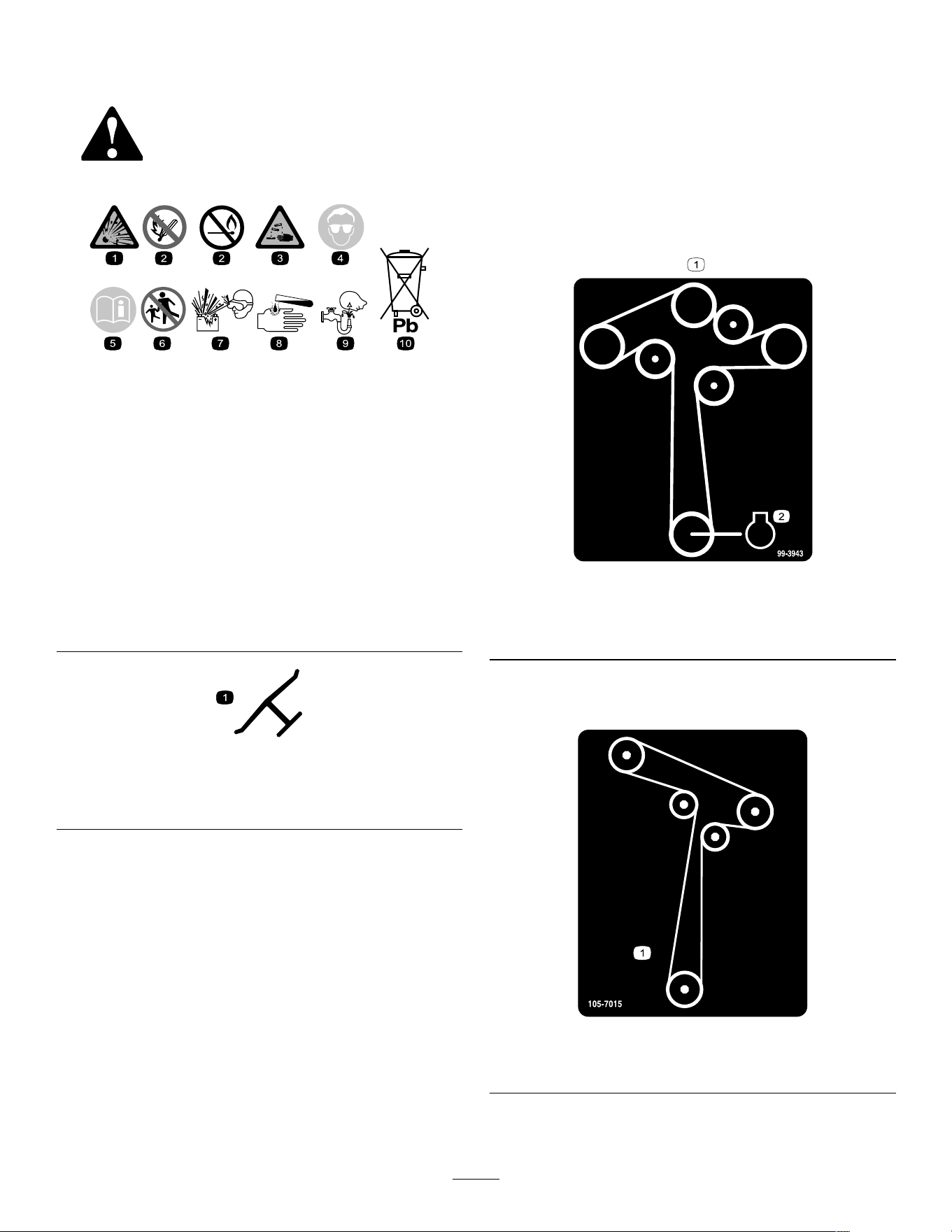
decalbatterysymbols
BatterySymbols
Someorallofthesesymbolsareonyourbattery.
1.Explosionhazard6.Keepbystandersaway
fromthebattery.
2.Nore,opename,or
smoking
7.Weareyeprotection;
explosivegasescan
causeblindnessandother
injuries.
3.Causticliquid/chemical
burnhazard
8.Batteryacidcancause
blindnessorsevereburns.
4.Weareyeprotection.9.Flusheyesimmediately
withwaterandgetmedical
helpfast.
5.ReadtheOperator's
Manual.
10.Containslead;donot
discard
decaloemmarkt
Manufacturer'sMark
1.Thismarkindicatesthatthebladeisidentiedasapart
fromtheoriginalmachinemanufacturer.
Decal99-3943isformodelswith127cm(50inch)or
137cm(54inch)decksonly.
decal99-3943
99-3943
1.Beltrouting
2.Engine
Decal105-7015isformodelswith107cm(42inch)
decksonly.
decal105-7015
105-7015
1.Beltrouting
6
Decal112-9840isformodelswith127cm(50inch)or
137cm(54inch)decksonly.
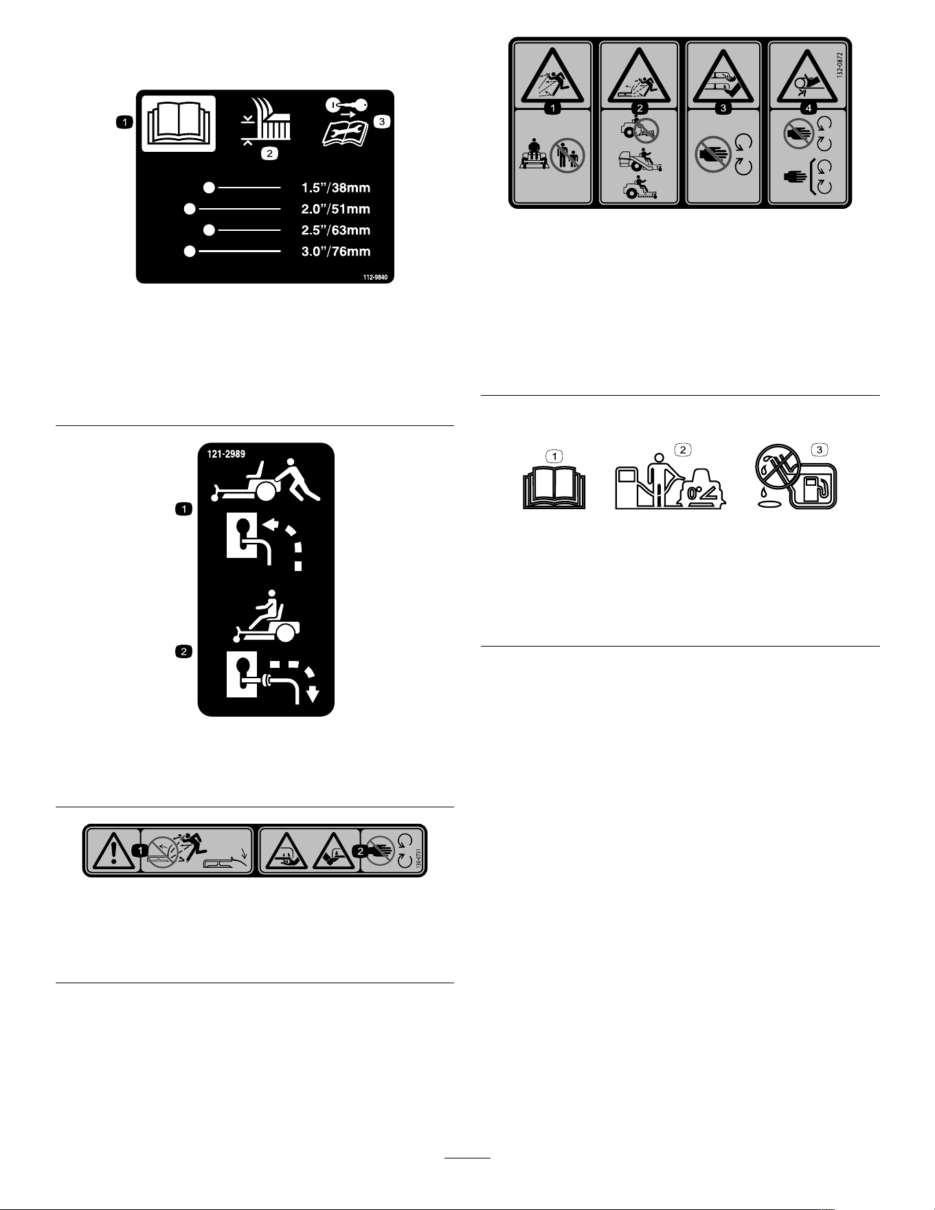
decal112-9840
112-9840
1.ReadtheOperator's
Manual.
3.Removetheignitionkey
andreadtheinstructions
beforeservicingor
performingmaintenance.
2.Heightofcut
decal121-2989b
121-2989
1.Bypassleverpositionfor
pushingthemachine
2.Bypassleverpositionfor
operatingthemachine
decal130-0731
130-0731
1.Warning—thrownobject
hazard;keepthedeector
shieldinplace.
2.Cuttinghazardofhandor
foot,mowerblade—keep
awayfrommovingparts.
decal132-0872
132-0872
1.Thrownobject
hazard—keepbystanders
awayfromthemachine.
3.Severinghazardofhand
orfoot—keepawayfrom
movingparts.
2.Thrownobjecthazard,
raiseddeector—donot
operatethemachinewith
anopendeck;usea
baggeroradeector.
4.Entanglement
hazard—keepaway
frommovingparts;keep
allguardsandshieldsin
place.
Decal138-6074ismoldedintothefueltank.
decal138-2456
138-6074
1.ReadtheOperator’s
Manual.
3.Donotoverllthefuel
tank.
2.Parkthemachineona
levelsurfacewhenlling
thefueltank.
7
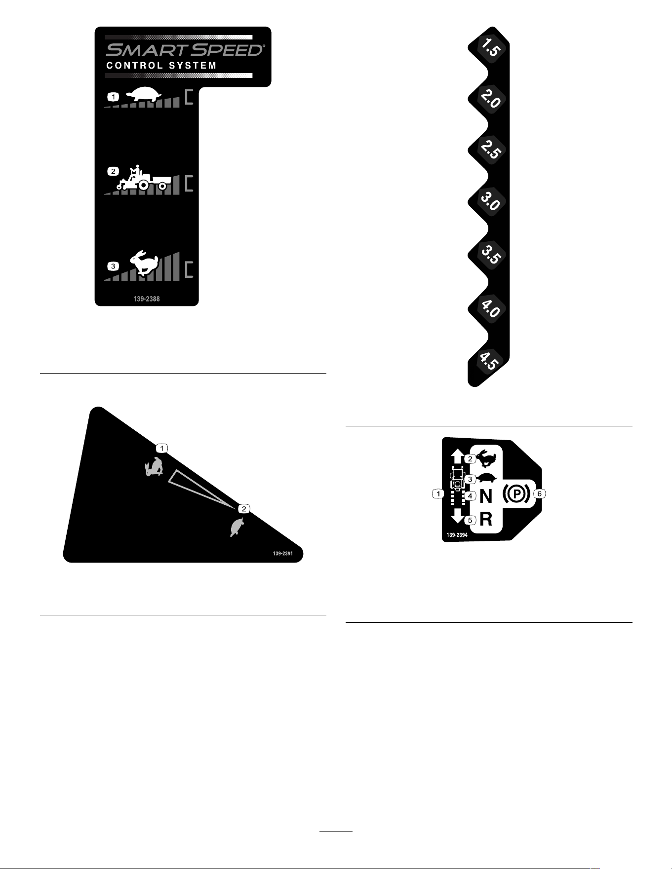
decal139-2388
139-2388
1.Slow
3.Fast
2.Hauling
Decal139-2391isformodelswithoutanhourmeter.
decal139-2391
139-2391
1.Fast
2.Slow
decal139-2392
139-2392
decal139-2394
139-2394
1.Tractioncontrols4.Neutral
2.Fast5.Reverse
3.Slow
6.Parkingbrake
8

decal139-2395
139-2395
1.Parkingbrake4.Neutral
2.Fast5.Reverse
3.Slow
6.Tractioncontrols
decal139-2397
139-2397
Decal140-2717isformodelswithanhourmeter.
decal140-2717
140-2717
1.Fast
2.Slow
decal142-5864
142-5864
9
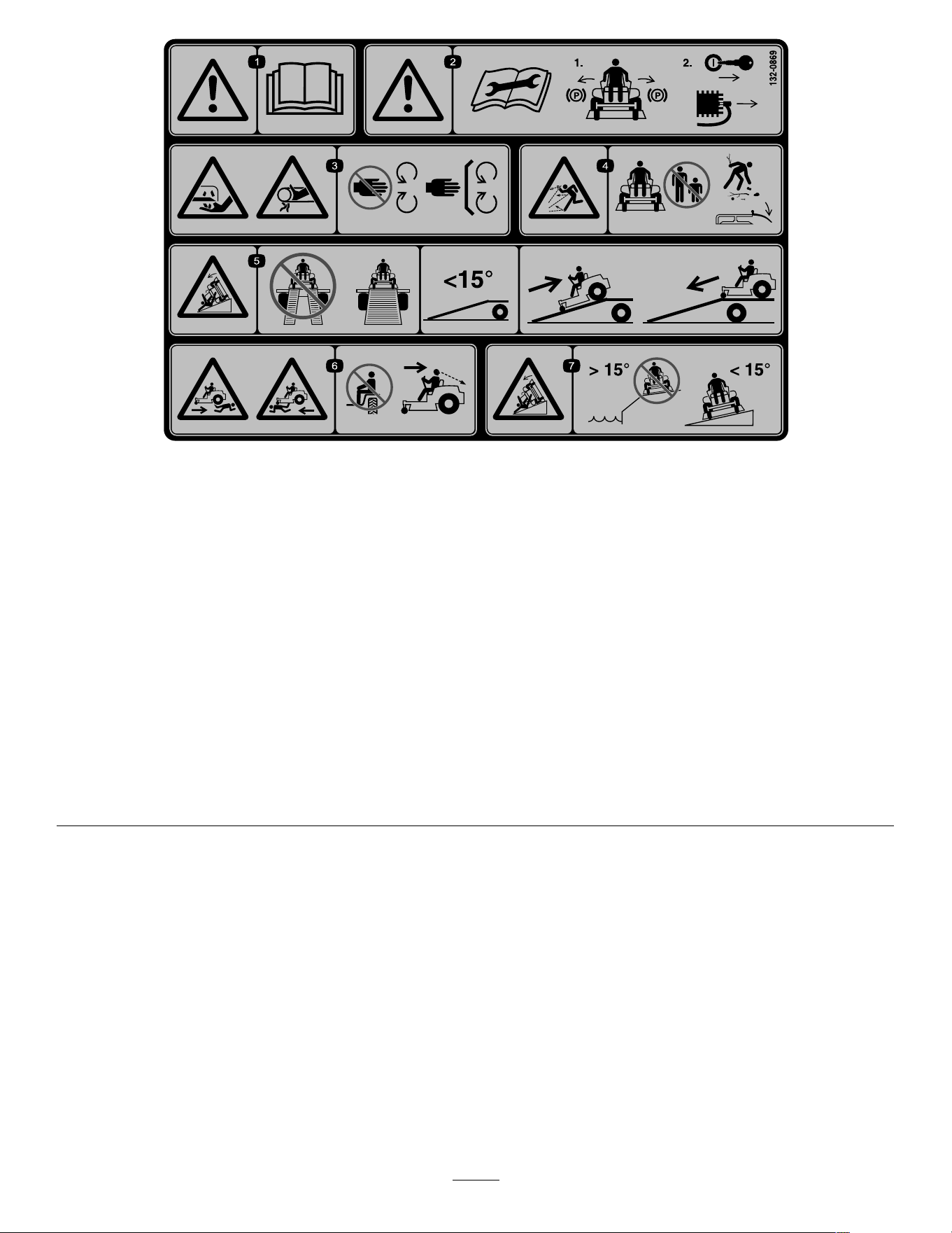
decal132-0869
132-0869
Note:Thismachinecomplieswiththeindustrystandardstabilitytestinthestaticlateralandlongitudinaltestswiththemaximum
recommendedslopeindicatedonthedecal.ReviewtheinstructionsforoperatingthemachineonslopesintheOperator’sManualas
wellastheconditionsinwhichyouwouldoperatethemachinetodeterminewhetheryoucanoperatethemachineintheconditionson
thatdayandatthatsite.Changesintheterraincanresultinachangeinslopeoperationforthemachine.
1.Warning—readthe
Operator'sManual.
3.Cutting/dismemberment
hazardofthehand,mower
blade;entanglement
hazardofthehand,
belt—stayawayfrom
movingparts;keepall
guardsandshieldsinplace.
5.Tippinghazard—donot
usedualrampswhen
loadingontoatrailer;use
1rampwideenoughfor
themachine;usearamp
withaslopelessthan15°;
backuptherampwhen
loadingthemachineand
driveforwardofftheramp
whenunloading.
7.Tippinghazard—donotuse
themachineneardrop-offs
oronslopesgreaterthan
15°;onlyoperateacross
slopeslessthan15°.
2.Warning—readthe
Operator'sManualbefore
performingmaintenance;
engagetheparkingbrake,
removethekey,and
disconnectthesparkplug.
4.Thrownobject
hazard—keepbystanders
away;pickupdebris
beforeoperating;keepthe
deectorinplace.
6.Runoverhazard—donot
carrypassengers;look
behindyouwhenmowing
inreverse.
10
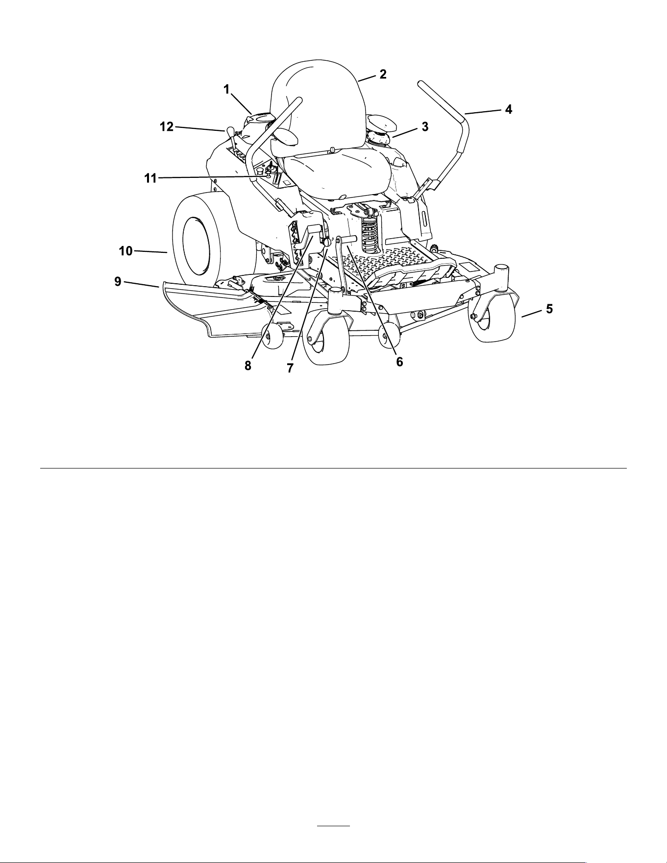
ProductOverview
g367815
Figure4
1.Engine4.Motion-controllevers
7.SmartSpeed™lever
10.Reardrivewheel
2.Operatorseat
5.Frontcasterwheel
8.Height-of-cutlever11.Controlpanel
3.Fuel-tankcap
6.Deck-liftpedal(certain
modelsonly)
9.Deector
12.MyRide™adjustmentlever
11
Controls
Becomefamiliarwithallthecontrolsbeforeyoustart
theengineandoperatethemachine.
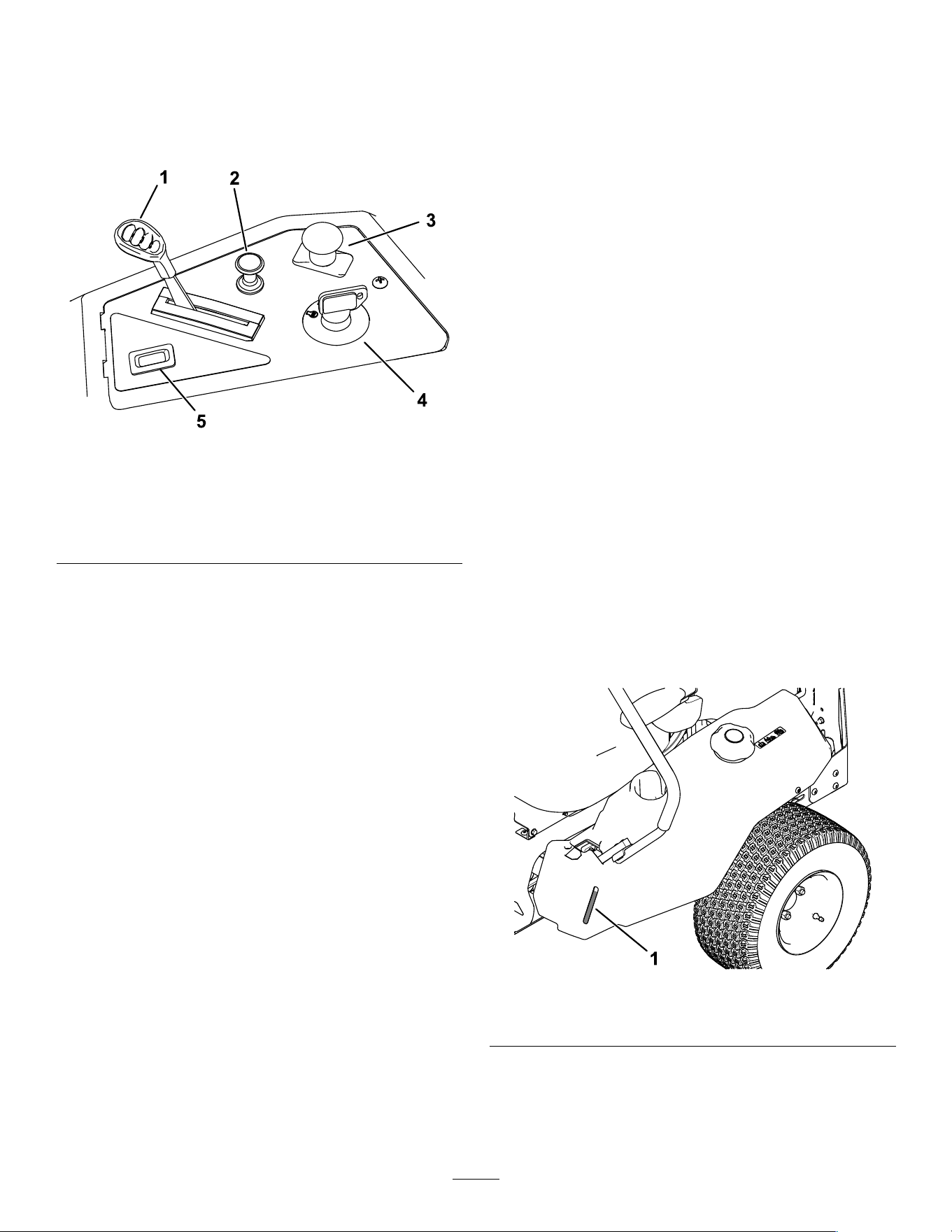
ControlPanel
g368287
Figure5
1.Throttlecontrol4.Keyswitch
2.Chokecontrol5.Hourmeter(ifequipped)
3.Blade-controlswitch
(powertakeoff)
KeySwitch
Thekeyswitch,usedtostartandshutofftheengine,
has3positions:OFF,RUN,andSTART(Figure5).
ThrottleControl
Thethrottlecontrolstheenginespeed,andithasa
continuous-variablesettingfromtheSLOWtoFAST
position(Figure5).
ChokeControl
Usethechokecontroltostartacoldengine(Figure5).
Blade-ControlSwitch(Power
Takeoff)
Theblade-controlswitch,representedbya
power-takeoff(PTO)symbol,engagesand
disengagespowertothemowerblades(Figure5).
HourMeter(IfEquipped)
Thehourmeterrecordsthenumberofhoursthe
enginehasoperated.Itoperateswhentheengine
isrunning.Usethesetimesforschedulingregular
maintenance(Figure5).
Motion-ControlLevers
Usethemotion-controlleverstodrivethemachine
forward,reverse,andturneitherdirection(Figure4).
ParkPosition
Movethemotion-controlleversoutwardfromthe
centertothePARKpositionwhenexitingthemachine
toengagetheelectricbrake(Figure20).Always
positionthemotion-controlleversintothePARK
positionwhenyoustopthemachineorleaveit
unattended.
MyRide®AdjustmentLever
UsetheMyRide®adjustmentlevertoadjusttheseat
suspension(Figure4).
SmartSpeed™ControlSystem
Lever
TheSmartSpeed™Control-Systemlever,located
belowtheoperatingposition,givesyouachoiceto
drivethemachineat3speedranges—trim,tow,and
mow(Figure23).
Fuel-PresenceWindow
Youcanusethefuelwindow,locatedontheleftside
ofthemachine,toverifythepresenceoffuelinthe
tank(Figure6).
g292100
Figure6
1.Fuel-presencewindow
12

Height-of-CutLever
Usetheheight-of-cutlevertolowerandraisethedeck
fromtheseatedposition.Movingtheleverup(toward
you)raisesthedeckfromthegroundandmovingthe
leverdown(awayfromyou)lowersthedecktoward
theground.Adjusttheheight-of-cutonlywhilethe
machineisnotmoving(Figure24).
FootPedalDeck-LiftSystem
CertainModelsOnly
Thefootpedaldeck-liftsystemallowsyoutolowerand
raisethedeckfromtheseatedposition.Youcanuse
thefootpedaltoliftthedeckbrieytoavoidobstacles
orassistinadjustingtheheightofcut(Figure4).
Specications
Specicationsanddesignaresubjecttochange
withoutnotice.
42inMower
Deck
50inMower
Deck
54inMower
Deck
Cuttingwidth107cm(42
inches)
127cm(50
inches)
137cm(54
inches)
Widthwith
deector
down
135cm(53
inches)
155cm(61
inches)
165cm(65
inches)
Widthwith
deector
raised
123cm(48.5
inches)
130cm(51
inches)
140cm(55
inches)
Length
185cm(73
inches)
186cm(73
inches)
187cm(73
inches)
Height
112cm(44
inches)
113cm(44
inches)
144cm(45
inches)
Weight724kg
(724lb)
353kg(779
lb)
379kg(836
lb)
Attachments/Accessories
AselectionofToroapprovedattachmentsand
accessoriesisavailableforusewiththemachine
toenhanceandexpanditscapabilities.Contact
yourAuthorizedServiceDealerorauthorizedToro
distributororgotowww.T oro.comforalistofall
approvedattachmentsandaccessories.
Toensureoptimumperformanceandcontinuedsafety
certicationofthemachine,useonlygenuineT oro
replacementpartsandaccessories.Replacement
partsandaccessoriesmadebyothermanufacturers
couldbedangerous,andsuchusecouldvoidthe
productwarranty.
Operation
Note:Determinetheleftandrightsidesofthe
machinefromthenormaloperatingposition.
BeforeOperation
BeforeOperationSafety
GeneralSafety
•Donotallowchildrenoruntrainedpeopleto
operateorservicethemachine.Localregulations
mayrestricttheageoftheoperator.Theowner
isresponsiblefortrainingalloperatorsand
mechanics.
•Inspecttheareawhereyouwillusethemachine,
andremoveallobjectsthatcouldinterferewith
theoperationofthemachineorthatthemachine
couldthrow.
•Becomefamiliarwiththesafeoperationofthe
equipment,operatorcontrols,andsafetysigns.
•Checkthatoperator-presencecontrols,safety
switches,andguardsareattachedandworking
properly.Donotoperatethemachineunlessthey
arefunctioningproperly.
•Shutofftheengine,removethekey,andwait
forallmovingpartstostopbeforeleavingthe
operator’sposition.Allowthemachinetocool
beforeservicing,adjusting,fueling,cleaning,or
storingit.
•Beforemowing,inspectthemachinetoensure
thatthecuttingassembliesareworkingproperly.
•Evaluatetheterraintodeterminetheappropriate
equipmentandanyattachmentsoraccessories
requiredtooperatethemachineproperlyand
safely.
•Wearappropriateclothing,includingeye
protection;longpants;substantial,slip-resistant
footwear;andhearingprotection.Tiebacklong
hairanddonotwearlooseclothingorloose
jewelry.
•Donotcarrypassengersonthemachine.
•Keepbystandersandpetsawayfromthemachine
duringoperation.Shutoffthemachineand
attachment(s)ifanyoneentersthearea.
•Donotoperatethemachineunlessallguardsand
safetydevices,suchasthedeectorsandthe
entiregrasscatcher,areinplaceandfunctioning
properly.Replacewornordeterioratedpartswhen
necessary.
13

FuelSafety
•Fuelisextremelyammableandhighlyexplosive.
Areorexplosionfromfuelcanburnyouand
othersandcandamageproperty.
–Topreventastaticchargefromignitingthe
fuel,removethemachinefromthetruckor
trailerandrefuelitontheground,awayfrom
allvehicles.Ifthisisnotpossible,placea
portablefuelcontainerontheground,away
fromallvehicles,andllit;thenrefuelthe
machinefromthefuelcontainerratherthan
fromafuel-dispensernozzle.
–Fillthefueltankoutdoorsonlevelground,in
anopenarea,andwhentheengineiscold.
Wipeupanyfuelthatspills.
–Donothandlefuelwhensmokingoraroundan
openameorsparks.
–Donotremovethefuelcaporaddfueltothe
tankwhiletheengineisrunningorhot.
–Ifyouspillfuel,donotattempttostartthe
engine.Avoidcreatingasourceofignitionuntil
thefuelvaporshavedissipated.
–Storefuelinanapprovedcontainerandkeep
itoutofthereachofchildren.
•Fuelisharmfulorfatalifswallowed.Long-term
exposuretovaporscancauseseriousinjuryand
illness.
–Avoidprolongedbreathingofvapors.
–Keepyourhandsandfaceawayfromthe
nozzleandthefuel-tankopening.
–Keepfuelawayfromyoureyesandskin.
•Donotstorethemachineorfuelcontainerwhere
thereisanopename,spark,orpilotlight,such
asonawaterheateroronotherappliances.
•Donotoperatethemachinewithouttheentire
exhaustsysteminplaceandinproperworking
condition.
•Keepthefuel-dispensernozzleincontactwith
therimofthefueltankorcontaineropeningat
alltimesuntilfuelingiscomplete.Donotusea
nozzlelock-opendevice.
•Ifyouspillfuelonyourclothing,changeyour
clothingimmediately.
•Donotoverllthefueltank.Replacethefuelcap
andtightenitsecurely.
•Cleangrassanddebrisfromthecuttingunit,
mufer,drives,grasscatcher,andengine
compartmenttohelppreventres.Cleanupoilor
fuelspills.
AddingFuel
RecommendedFuel
TypeUnleadedgasoline
Minimumoctanerating
87(US)or91(research
octane;outsidetheUS)
Ethanol
Nomorethan10%byvolume
MethanolNone
MTBE(methyltertiarybutyl
ether)
Lessthan15%byvolume
OilDonotaddtothefuel
Useonlyclean,fresh(nomorethan30daysold),fuel
fromareputablesource.
UsingStabilizer/Conditioner
Usefuelstabilizer/conditionerinthemachinetokeep
thefuelfreshlongerwhenusedasdirectedbythe
fuel-stabilizermanufacturer.
Important:Donotusefueladditivescontaining
methanolorethanol.
Addtheamountoffuelstabilizer/conditionertofresh
fuelasdirectedbythefuel-stabilizermanufacturer.
FillingtheFuelTank
1.Parkthemachineonalevelsurface.
2.Movethemotion-controlleversoutwardtothe
PARKposition.
3.Shutofftheengineandremovethekey.
4.Cleanaroundthefuel-tankcap.
5.Fillthefueltanktothebottomofthellerneck
(Figure7).Donotllthefueltankcompletelyfull
14
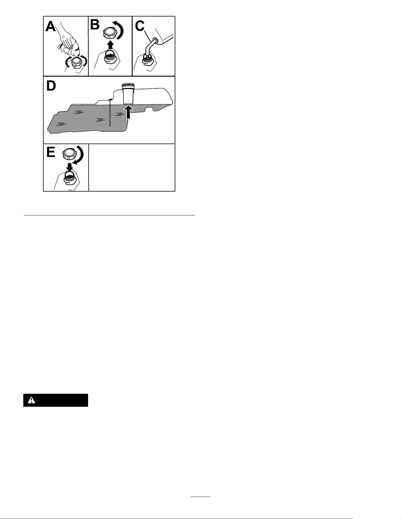
g293796
Figure7
PerformingDaily
Maintenance
Beforestartingthemachineeachday,performthe
EachUse/DailyprocedureslistedinMaintenance
(page29).
BreakinginaNewMachine
Newenginestaketimetodevelopfullpower.Mower
decksanddrivesystemshavehigherfrictionwhen
new,placingadditionalloadontheengine.Allow
40to50hoursofbreak-intimefornewmachinesto
developfullpowerandbestperformance.
UsingtheSafety-Interlock
System
WARNING
Ifthesafety-interlockswitchesare
disconnectedordamaged,themachinecould
operateunexpectedly,causingpersonal
injury.
•Donottamperwiththeinterlockswitches.
•Checktheoperationoftheinterlock
switchesdailyandreplaceanydamaged
switchesbeforeoperatingthemachine.
Understandingthe
Safety-InterlockSystem
Thesafety-interlocksystemisdesignedtopreventthe
enginefromstartingunless:
•Theblade-controlswitch(PTO)isdisengaged.
•Themotion-controlleversareinthePARKposition.
Thesafety-interlocksystemalsoisdesignedtoshut
offtheenginewheneverthecontrolleversareoutof
thePARKpositionandyourisefromtheseat.
TestingtheSafety-Interlock
System
Testthesafety-interlocksystembeforeyouusethe
machineeachtime.Ifthesafetysystemdoesnot
operateasdescribedbelow,haveanAuthorized
ServiceDealerrepairthesafetysystemimmediately.
1.Sitontheseat,movethemotion-controllevers
inthePARKposition,andmovetheblade-control
switchtotheONposition.Trystartingthe
engine;theengineshouldnotcrank.
2.Sitontheseatandmovetheblade-controlswitch
totheOFFposition.Moveeithermotion-control
levertothecenter,unlockedposition.Try
startingtheengine;theengineshouldnotcrank.
Repeatwiththeothermotion-controllever.
3.Sitontheseat,movetheblade-controlswitch
totheOFFposition,andlockthemotion-control
leversinthePARKposition.Starttheengine.
Whiletheengineisrunning,engagethe
blade-controlswitch,andriseslightlyfromthe
seat;theengineshouldshutoff.
4.Sitontheseat,movetheblade-controlswitch
totheOFFposition,andlockthemotion-control
leversinthePARKposition.Starttheengine.
Whiletheengineisrunning,movethe
motion-controlleverstothecenter,unlocked
positionandriseslightlyfromtheseat;the
engineshouldshutoff.
15
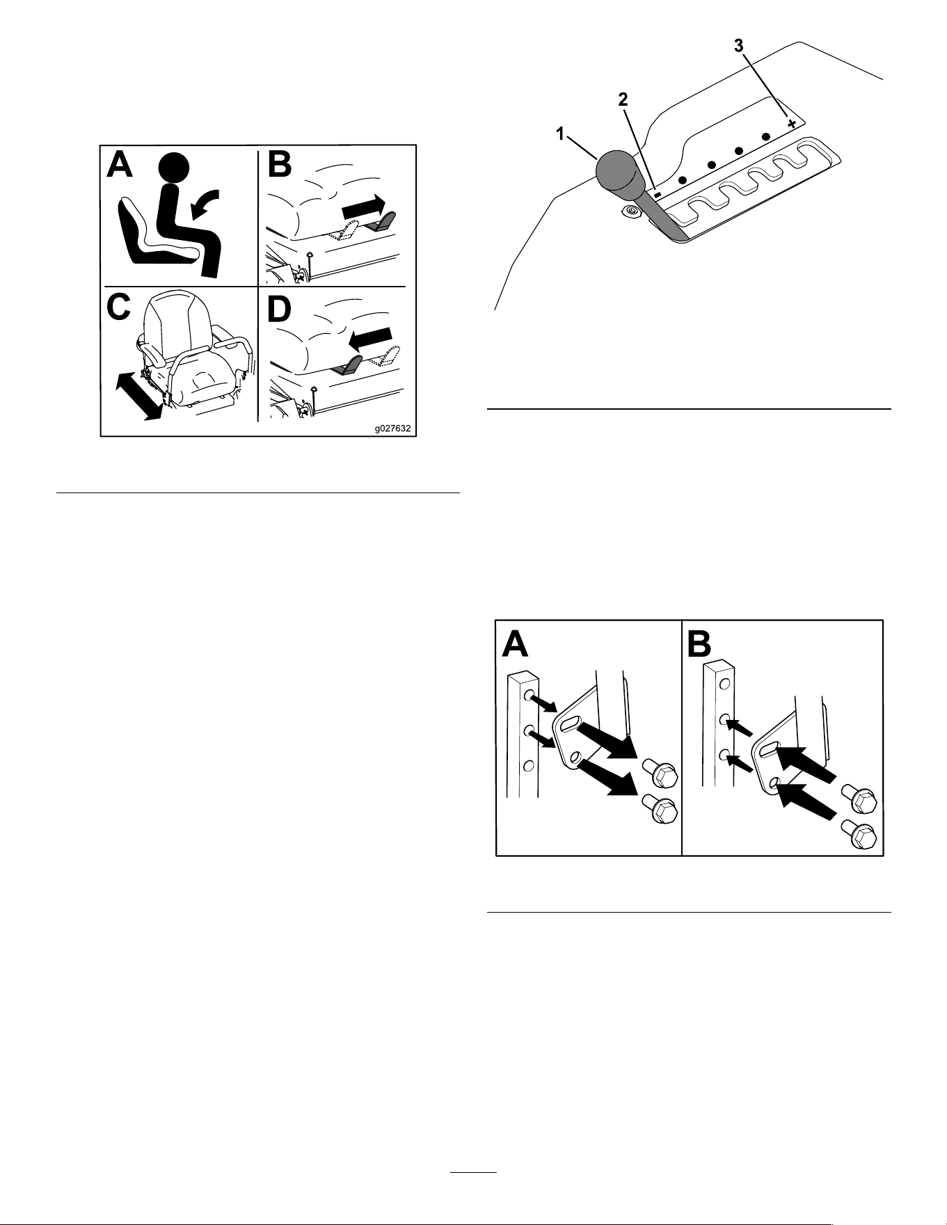
PositioningtheSeat
Theseatcanmoveforwardandbackward.Position
theseatwhereyouhavethebestcontrolofthe
machineandaremostcomfortable(Figure8).
g027632
Figure8
AdjustingtheMyRide®
SuspensionSystem
YoucanadjusttheMyRide®suspensionsystemfora
smoothandcomfortableride.Theslotsforadjusting
thesuspensionhavedetentpositionsforreference,
rangingfromasofttoarmride(Figure9).
1.Parkthemachineonalevelsurface,disengage
theblade-controlswitch,andmovethe
motion-controlleversoutwardtothePARK
position.
2.Shutofftheengine,removethekey,andwait
forallmovingpartstostopbeforeleavingthe
operatingposition.
3.Stepoffthemachine.
4.Whilestandingontherightsideofthemachine,
movetheadjustmentleverlefttowardthe–
symbolforasoftersuspension.
Movetheadjustmentleverrighttowardthe+
symbolforarmersuspension.
g292102
Figure9
1.MyRideadjustmentlever3.Firmersuspension
2.Softersuspension
Adjustingthe
Motion-ControlLevers
AdjustingtheHeight
Youcanadjustthemotion-controllevershigheror
lowerformaximumcomfort(Figure10).
g333847
Figure10
AdjustingtheTilt
Youcanadjustthemotion-controlleversforwardor
rearwardforyourcomfort.
1.Loosentheupperboltholdingthecontrollever
tothecontrol-armshaft.
2.Loosenthelowerboltjustenoughtopivotthe
controlleverforwardorrearward.
16
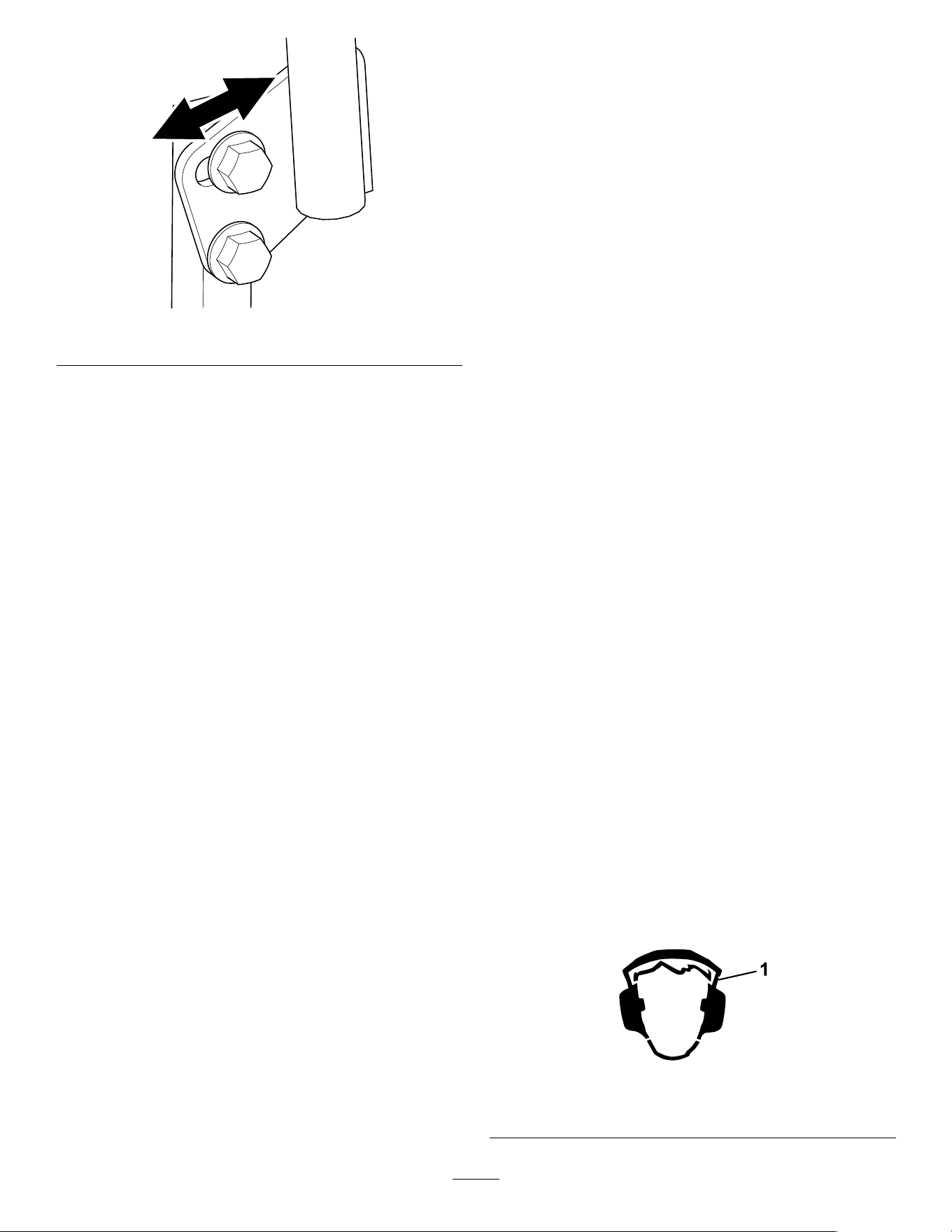
g333846
Figure11
3.Tightenbothboltstosecurethecontrolleverin
thenewposition.
4.Repeattheadjustmentfortheothercontrollever.
DuringOperation
DuringOperationSafety
GeneralSafety
•Theowner/operatorcanpreventandisresponsible
foraccidentsthatmaycausepersonalinjuryor
propertydamage.
•Useyourfullattentionwhileoperatingthe
machine.Donotengageinanyactivitythat
causesdistractions;otherwise,injuryorproperty
damagemayoccur.
•Donotoperatethemachinewhileill,tired,or
undertheinuenceofalcoholordrugs.
•Contactingthebladecanresultinseriouspersonal
injury.Shutofftheengine,removethekey,and
waitforallmovingpartstostopbeforeleavingthe
operatingposition.Whenyouturnthekeytothe
OFFposition,theengineshouldshutoffandthe
bladeshouldstop.Ifnot,stopusingyourmachine
immediatelyandcontactanAuthorizedService
Dealer.
•Operatethemachineonlyingoodvisibilityand
appropriateweatherconditions.Donotoperate
themachinewhenthereistheriskoflightning.
•Keepyourhandsandfeetawayfromthecutting
units.Keepclearofthedischargeopening.
•Donotmowwiththedischargedeector
raised,removed,oralteredunlessthereisa
grass-collectionsystemormulchkitinplaceand
workingproperly.
•Donotmowinreverseunlessitisabsolutely
necessary.Alwayslookdownandbehindyou
beforemovingthemachineinreverse.
•Useextremecarewhenapproachingblind
corners,shrubs,trees,orotherobjectsthatmay
blockyourview.
•Stopthebladeswheneveryouarenotmowing.
•Ifthemachinestrikesanobjectorstartstovibrate,
immediatelyshutofftheengine,removethekey
(ifequipped),andwaitforallmovingpartstostop
beforeexaminingthemachinefordamage.Make
allnecessaryrepairsbeforeresumingoperation.
•Slowdownandusecautionwhenmakingturns
andcrossingroadsandsidewalkswiththe
machine.Alwaysyieldtheright-of-way.
•Beforeyouleavetheoperatingposition,dothe
following:
–Parkthemachineonalevelsurface.
–Disengagethepowertakeoffandlowerthe
attachments.
–Engagetheparkingbrake.
–Shutofftheengineandremovethekey.
–Waitforallmovingpartstostop.
•Operatetheengineonlyinwell-ventilatedareas.
Exhaustgasescontaincarbonmonoxide,which
islethalifinhaled.
•Neverleavearunningmachineunattended.
•Attachtowedequipmenttothemachineonlyat
thehitchpoint.
•Donotoperatethemachineunlessallguardsand
safetydevices,suchasthedeectorsandthe
entiregrasscatcher,areinplaceandfunctioning
properly.Replacewornordeterioratedpartswhen
necessary.
•Useonlyaccessoriesandattachmentsapproved
byT oro.
•Thismachineproducessoundlevelsinexcess
of85dBAattheoperator’searandcancause
hearinglossthroughextendedperiodsof
exposure.
g229846
Figure12
1.Wearhearingprotection.
17
•Cleangrassanddebrisfromthecuttingunit,
drives,mufer,andenginetohelppreventres.
•Starttheenginewithyourfeetwellawayfromthe
blades.
•Beawareofthemowerdischargepathanddirect
thedischargeawayfromothers.Avoiddischarging
materialagainstawallorobstructionbecausethe
materialmayricochetbacktowardyou.
•Stoptheblades,slowdownthemachine,anduse
cautionwhencrossingsurfacesotherthangrass
orwhentransportingthemachinetoandfromthe
operatingarea.
•Donotchangetheenginegovernorspeedor
overspeedtheengine.
•Childrenareoftenattractedtothemachineand
themowingactivity.Neverassumethatchildren
willremainwhereyoulastsawthem.
•Keepchildrenoutoftheoperatingareaandunder
thewatchfulcareofaresponsibleadultotherthan
theoperator.
•Bealertandshutoffthemachineifchildrenenter
theoperatingarea.
•Beforebackinguporturningthemachine,look
downandallaroundforsmallchildren.
•Donotcarrychildrenonthemachine,evenwhen
thebladesarenotmoving.Childrencouldfall
offandbeseriouslyinjuredorpreventyoufrom
safelyoperatingthemachine.Childrenwhohave
beengivenridesinthepastcouldappearinthe
operatingareawithoutwarningandberunoveror
backedoverbythemachine.
SlopeSafety
•Slopesareamajorfactorrelatedtolossofcontrol
androlloveraccidents,whichcanresultinsevere
injuryordeath.Theoperatorisresponsiblefor
safeslopeoperation.Operatingthemachineon
anysloperequiresextracaution.Beforeusingthe
machineonaslope,dothefollowing:
–Reviewandunderstandtheslopeinstructions
inthemanualandonthemachine.
–Useanangleindicatortodeterminethe
approximateslopeangleofthearea.
–Neveroperateonslopesgreaterthan15°.
–Evaluatethesiteconditionsofthedayto
determineiftheslopeissafeformachine
operation.Usecommonsenseandgood
judgmentwhenperformingthisevaluation.
Changesintheterrain,suchasmoisture,can
quicklyaffecttheoperationofthemachineon
aslope.
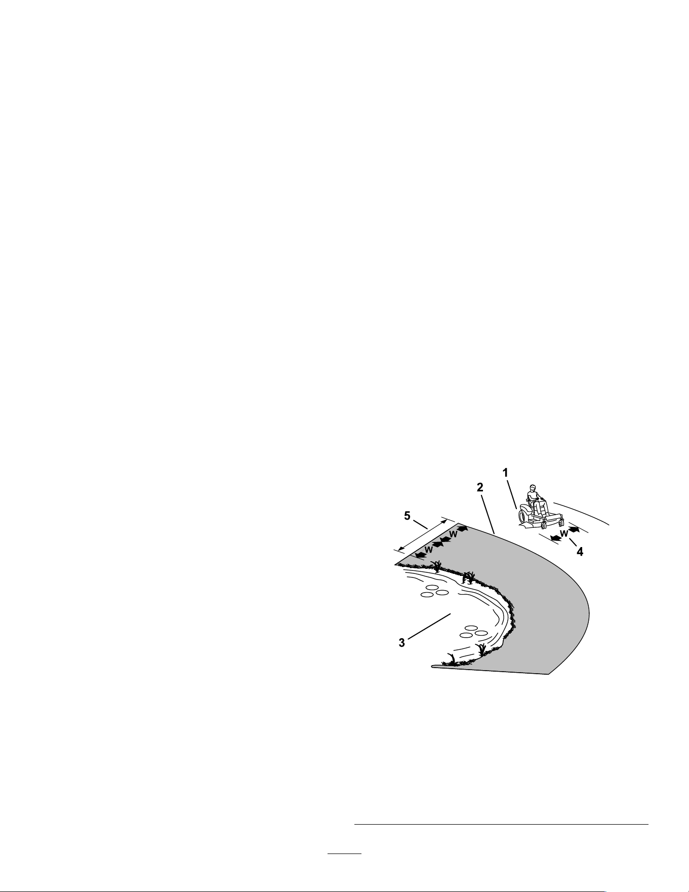
•Identifyhazardsatthebaseoftheslope.Do
notoperatethemachineneardrop-offs,ditches,
embankments,water,orotherhazards.The
machinecouldsuddenlyrolloverifawheelgoes
overtheedgeortheedgecollapses.Keepasafe
distance(twicethewidthofthemachine)between
themachineandanyhazard.Useawalk-behind
machineorahandtrimmertomowthegrassin
theseareas.
•Avoidstarting,stopping,orturningthemachineon
slopes.Avoidmakingsuddenchangesinspeedor
direction;turnslowlyandgradually.
•Donotoperateamachineunderanyconditions
wheretraction,steering,orstabilityisinquestion.
Beawarethatoperatingthemachineonwet
grass,acrossslopes,ordownhillmaycausethe
machinetolosetraction.Lossoftractiontothe
drivewheelsmayresultinslidingandalossof
brakingandsteering.Themachinecanslideeven
ifthedrivewheelsarestopped.
•Removeormarkobstaclessuchasditches,holes,
ruts,bumps,rocks,orotherhiddenhazards.T all
grasscanhideobstacles.Uneventerraincould
overturnthemachine.
•Useextracarewhileoperatingwithaccessoriesor
attachments,suchasgrass-collectionsystems.
Thesecanchangethestabilityofthemachine
andcausealossofcontrol.Followdirectionsfor
counterweights.
•Ifpossible,keepthedeckloweredtotheground
whileoperatingonslopes.Raisingthedeckwhile
operatingonslopescancausethemachineto
becomeunstable.
g229111
Figure13
1.SafeZone—usethe
machinehereonslopes
lessthan15°oratareas.
4.W=Widthofthemachine
2.DangerZone—usea
walk-behindmowerand/or
ahandtrimmeronslopes
greaterthan15°andnear
drop-offsorwater.
5.Keepasafedistance
(twicethewidthofthe
machine)betweenthe
machineandanyhazard.
3.Water
18
TowingSafety
•Donotattachtowedequipmentexceptatthehitch
point.
•Donotusethemachineasatowingvehicleunless
ithasahitchinstalled.
•Donotexceedtheweightlimitsfortowed
equipmentandtowingonslopes.Thetowed
weightmustnotexceedtheweightofthemachine
andoperator.
•Neverallowchildrenorothersnearthetowed
equipment.
•Onslopes,theweightofthetowedequipmentmay
causelossoftraction,increasedriskofrollover,
andlossofcontrol.Reducethetowedweightand
slowdown.
•Thestoppingdistancemayincreasewiththe
weightofatowedload.Travelslowlyandallow
extradistancetostop.
•Makewideturnstokeeptheattachmentclearof
themachine.
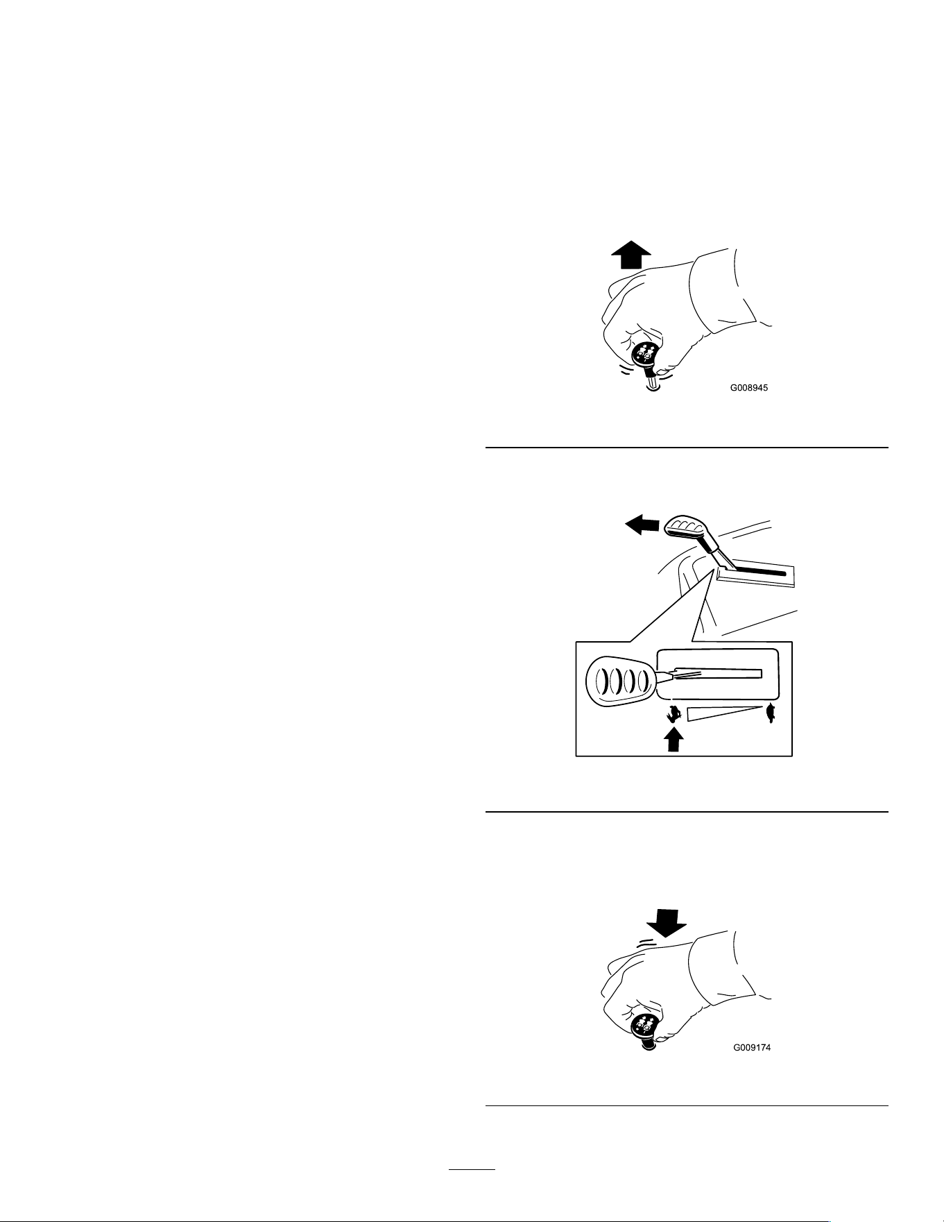
OperatingtheMower
Blade-ControlSwitch(PTO)
Theblade-controlswitch(PTO)startsandstopsthe
mowerbladesandanypoweredattachments.
EngagingtheBlade-Control
Switch(PTO)
g008945
Figure14
Note:Alwaysengagethebladeswiththethrottlein
theFASTposition(Figure15).
g295538
Figure15
DisengagingtheBlade-Control
Switch(PTO)
g009174
Figure16
19
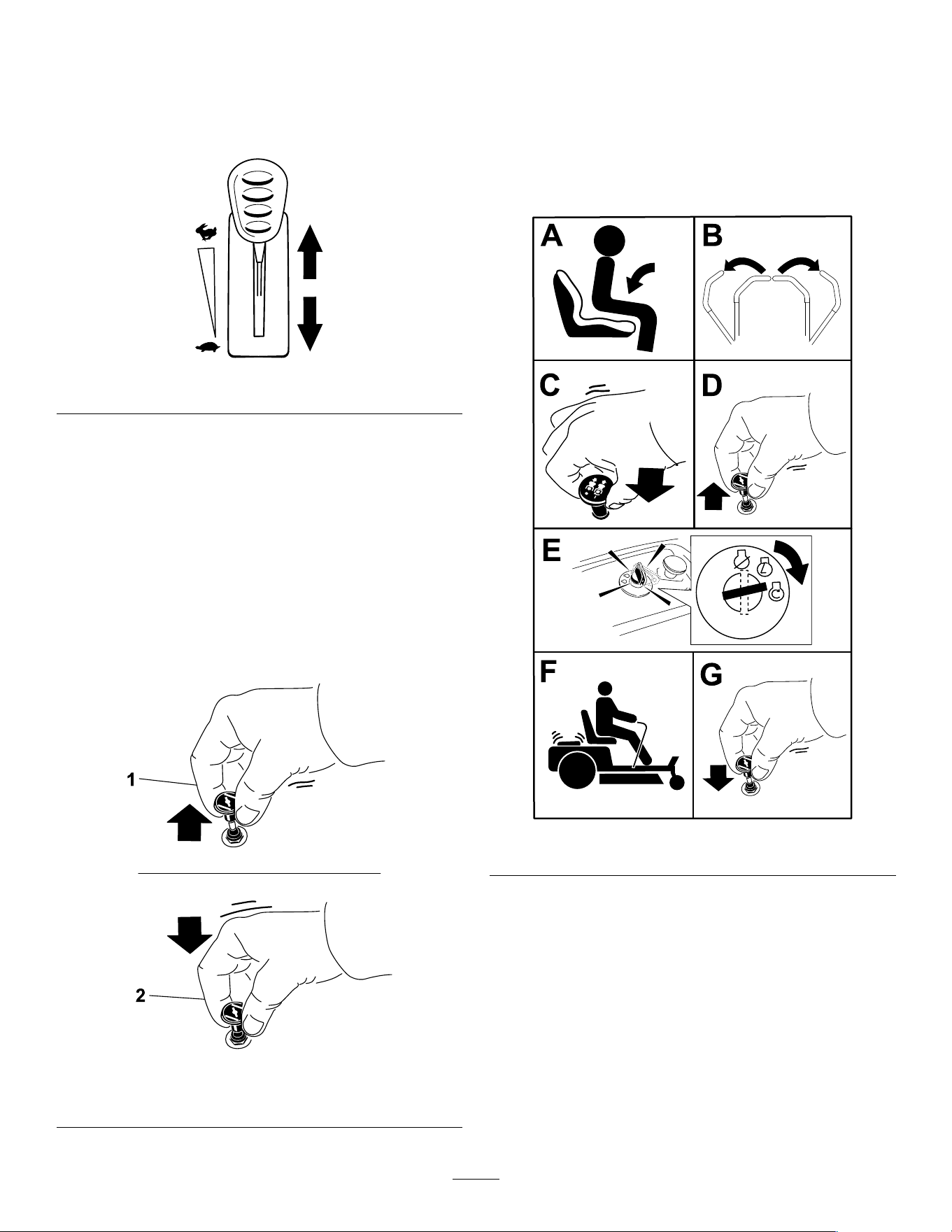
OperatingtheThrottle
YoucanmovethethrottlecontrolbetweentheFAST
andSLOWpositions(Figure17).
AlwaysusetheFASTpositionwhenengagingthePTO.
g295539
Figure17
OperatingtheChoke
Usethechoketostartacoldengine.
1.Pullupthechokeknobtoengagethechoke
beforeusingthekeyswitch(Figure18).
Note:Ensurethatyoufullyengagethechoke.
Youmayneedtoholdtheknobupwhenyou
usethekeyswitch.
2.Pushdownthechoketodisengagethechoke
aftertheenginehasstarted(Figure18).
g295540
Figure18
1.ONposition2.OFFposition
StartingtheEngine
Note:Awarmorhotenginemaynotrequirechoking.
Important:Donotengagethestarterformore
than5secondsatatime.Engagingthestarter
motorformorethan5secondscandamagethe
startermotor.Iftheenginefailstostart,wait10
secondsbeforeoperatingtheenginestarteragain.
g295541
Figure19
20
ShuttingOfftheEngine
1.Disengagethebladesbymovingthe
blade-controlswitchtotheOFFposition.
2.Movethemotion-controlleversoutwardtothe
PARKposition.
3.Movethethrottlecontroltobetweenthehalfand
fullthrottleposition.
4.TurnthekeytotheOFFpositionandremove
thekey.
CAUTION
Childrenorbystandersmaybeinjuredifthey
moveorattempttooperatethemachinewhile
itisunattended.
Alwaysremovethekeyandengagethe
parkingbrakewhenleavingthemachine
unattended.
UsingtheMotion-Control
Levers
g004532
Figure20
1.Motion-control
lever—PARKposition
4.Backward
2.Center,unlockedposition5.Frontofmachine
3.Forward
DrivingtheMachine
Thedrivewheelsturnindependently,poweredby
hydraulicmotorsoneachaxle.Youcanturn1side
inreversewhileyouturntheotherforward,causing
themachinetospinratherthanturn.Thisgreatly
improvesthemachinemaneuverabilitybutmay
requiresometimeforyoutoadapttohowitmoves.
Thethrottlecontrolregulatestheenginespeedas
measuredinrpm(revolutionsperminute).Place
thethrottlecontrolintheFASTpositionforbest
performance.Alwaysoperateinthefullthrottle
positionwhenmowing.
WARNING
Themachinecanspinveryrapidly.You
maylosecontrolofthemachineandcause
personalinjuryordamagetothemachine.
•Usecautionwhenmakingturns.
•Slowthemachinedownbeforemaking
sharpturns.
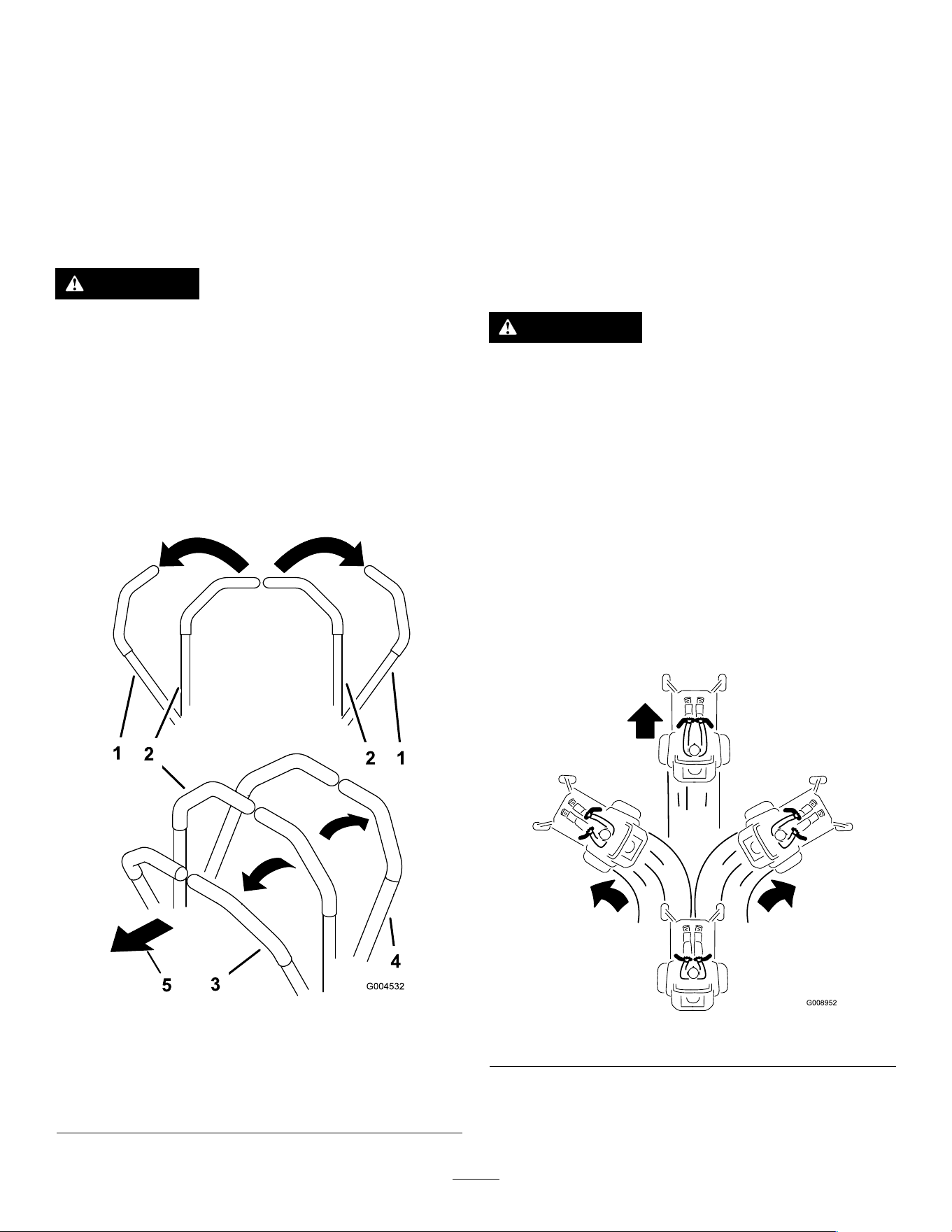
DrivingForward
Note:Alwaysusecautionwhenbackingupand
turning.
1.Movetheleverstothecenter,unlockedposition.
2.Togoforward,slowlypushthemotion-control
leversforward(Figure21).
g008952
Figure21
21
DrivingBackward
1.Movetheleverstothecenter,unlockedposition.
2.Togobackward,slowlypullthemotion-control
leversrearward(Figure22).
g008953
Figure22
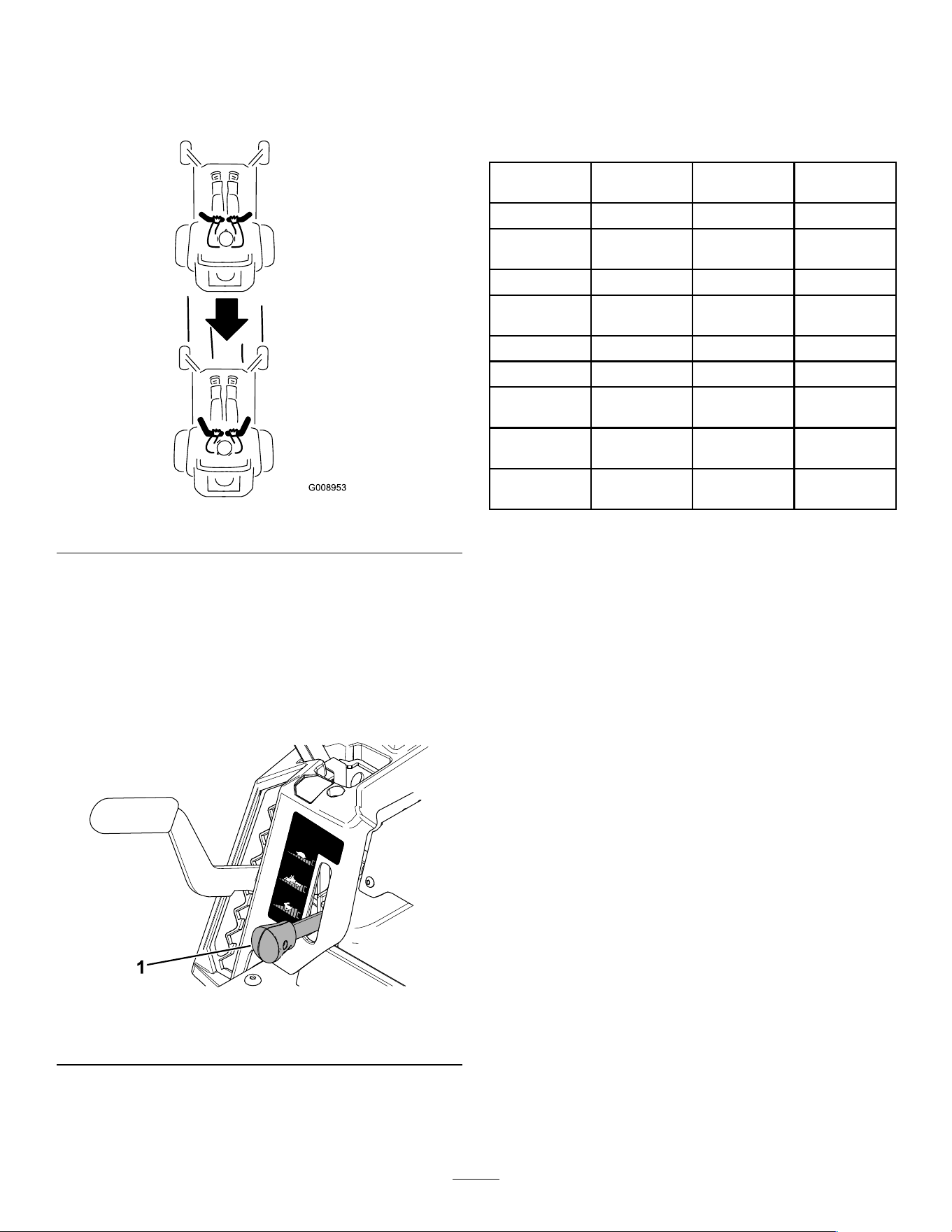
UsingtheSmartSpeed
TM
ControlSystem
TheSmartSpeed
TM
Control-Systemlever,located
belowtheoperatingposition(Figure23),givesthe
operatorachoicetodrivethemachineat3ground
speedranges—trim,tow,andmow.
g293338
Figure23
1.Smart-speedlever
Tochangespeeds,dothefollowing:
1.Movethemotion-controlleverstoneutraland
outwardtothePARKposition.
2.Disengagetheblade-controlswitch.
3.Adjustthelevertothedesiredposition.
Thefollowingareonlyrecommendationsforuse.
Adjustmentsvarybygrasstype,moisturecontent,
andtheheightofthegrass.
Suggested
uses:
TrimT owMow
ParkingX
Heavy,wet
grass
X
TrainingX
Trimming
grass
X
BaggingX
MulchingX
Towing
attachments
X
Normal
mowing
X
Movingthe
machine
X
Trim
Thisisthelowestspeed.Thesuggestedusesforthis
speedareasfollows:
•Parking
•Heavy,wetgrassmowingconditions
•Training
•Trimminggrass
Tow
Thisisthemediumspeed.Thesuggestedusesfor
thisspeedareasfollows:
•Bagging
•Mulching
•Towingattachments
Mow
Thisisthefastestspeed.Thesuggestedusesforthis
speedareasfollows:
•Normalmowing
•Movingthemachine
22
UsingtheSideDischarge
Themowerhasahingedgrassdeectorthat
dispersesclippingstothesideanddowntowardthe
turf.
DANGER
Withoutagrassdeector,dischargecover,or
acompletegrass-catcherassemblymounted
inplace,youandothersareexposedtoblade
contactandthrowndebris.Contactwith
rotatingmowerblade(s)andthrowndebris
willcauseinjuryordeath.
•Neverremovethegrassdeectorfromthe
mowerdeckbecausethegrassdeector
routesmaterialdowntowardtheturf.Ifthe
grassdeectoriseverdamaged,replaceit
immediately.
•Neverputyourhandsorfeetunderthe
mowerdeck.
•Nevertrytoclearthedischargearea
ormowerbladesunlessyoumovethe
blade-controlswitch(PTO)totheOFF
position,rotatethekeyswitchtotheOFF
position,andremovethekeyfromthekey
switch.
•Makesurethatthegrassdeectorisinthe
downposition.
AdjustingtheHeightofCut
Note:Thetransportpositionisthehighest
height-of-cutpositionorcuttingheightat114mm
(4-1/2inches)asshowninFigure24.
Youcanadjusttheheightofcutfrom38to114mm
(1-1/2to4-1/2inches)in13mm(1/2inch)increments.
Theheightofcutiscontrolledbytheleverlocatedto
therightoftheoperatingposition(Figure24).
g296586
Figure24
23
AdjustingtheAnti-Scalp
Rollers
Machineswith107cm(42-inch)
MowerDecks
Wheneveryouchangetheheightofcut,adjustthe
heightoftheanti-scalprollers.
Note:Adjusttheanti-scalprollerssothattherollers
donottouchthegroundinnormal,atmowingareas.
1.Parkthemachineonalevelsurface,disengage
theblade-controlswitch,andmovethe
motion-controlleversoutwardtothePARK
position.
2.Shutofftheengine,removethekey,andwait
forallmovingpartstostopbeforeleavingthe
operatingposition.
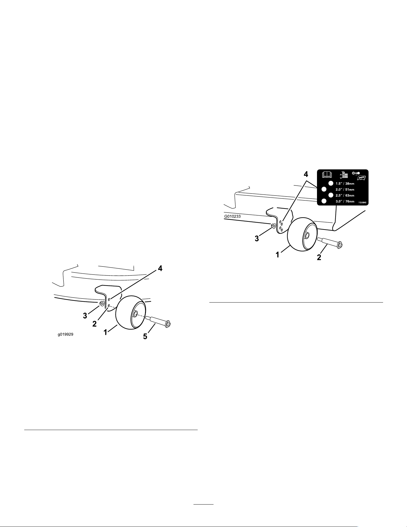
3.Adjusttheanti-scalprollersto1ofthefollowing
positions:
•Upperhole—usethispositionwiththemower
deckinthe63mm(2-1/2inches)andbelow
theheight-of-cutpositions(Figure25).
•Lowerhole—usethispositionwiththemower
deckinthe76mm(3inches)andabovethe
height-of-cutpositions(Figure25).
g019929
Figure25
1.Anti-scalproller4.Upperhole—themower
deckinthe63mm(2-1/2
inches)andbelowthe
height-of-cutpositions
2.Lowerhole—themower
deckinthe76mm(3
inches)andabovethe
height-of-cutpositions
5.Bolt
3.Flangenut
Machineswith127cm(50-inch)or
137cm(54-inch)MowerDecks
Wheneveryouchangetheheightofcut,adjustthe
heightoftheanti-scalprollers.
Note:Adjusttheanti-scalprollerssothattherollers
donottouchthegroundinnormal,atmowingareas.
1.Parkthemachineonalevelsurface,disengage
theblade-controlswitch,andmovethe
motion-controlleversoutwardtothePARK
position.
2.Shutofftheengine,removethekey,andwait
forallmovingpartstostopbeforeleavingthe
operatingposition.
3.Adjusttheanti-scalprollers(Figure26)tomatch
theclosestheight-of-cutposition.
g010233
Figure26
1.Anti-scalproller3.Flangenut
2.Bolt4.Holespacing
24

OperatingTips
MaximizingAirCirculation
Forbestmowingandmaximumaircirculation,operate
theengineattheFASTposition.Airisrequiredto
thoroughlycutgrassclippings,sodonotsetthe
height-of-cutsolowastototallysurroundthemower
deckinuncutgrass.Alwaystrytohave1sideofthe
mowerdeckfreefromuncutgrass,whichallowsair
tobedrawnintothemowerdeck.
CuttingaLawnfortheFirstTime
Cutgrassslightlylongerthannormaltoensurethat
thecuttingheightofthemowerdeckdoesnotscalp
anyunevenground.However,thecuttingheight
usedinthepastisgenerallythebestonetouse.
Whencuttinggrasslongerthan15cm(6inches)tall,
youmaywanttocutthelawntwicetoensurean
acceptablequalityofcut.
CuttingaThirdoftheGrassBlade
Itisbesttocutonlyaboutathirdofthegrassblade.
Cuttingmorethanthatisnotrecommendedunless
grassissparse,oritislatefallwhengrassgrows
moreslowly.
AlternatingtheMowingDirection
Alternatethemowingdirectiontokeepthegrass
standingstraight.Thisalsohelpsdisperseclippings,
whichenhancesdecompositionandfertilization.
MowingatCorrectIntervals
Grassgrowsatdifferentratesatdifferenttimesof
theyear.Tomaintainthesamecuttingheight,mow
moreofteninearlyspring.Asthegrassgrowthrate
slowsinmidsummer,mowlessfrequently.Ifyou
cannotmowforanextendedperiod,rstmowata
highcuttingheight,thenmowagain2dayslaterata
lowerheightsetting.
MowingatSlowerSpeeds
Incertainconditions,mowingataslowerground
speedcanimprovecutquality.
AvoidingCuttingTooLow
Whenmowinguneventurf,raisethecuttingheight
toavoidscalpingtheturf.
StoppingtheMachine
Ifyoumuststoptheforwardmotionofthemachine
whilemowing,aclumpofgrassclippingsmay
dropontoyourlawn.T oavoidthis,moveontoa
previouslycutareawiththebladesengagedoryou
candisengagethemowerdeckwhilemovingforward.
KeepingtheUndersideofthe
MowerDeckClean
Cleanclippingsanddirtfromtheundersideofthe
mowerdeckaftereachuse.Ifgrassanddirtbuildup
insidethemowerdeck,cuttingqualitywilleventually
becomeunsatisfactory.
MaintainingtheBlade(s)
Maintainasharpbladethroughoutthecuttingseason
becauseasharpbladecutscleanlywithouttearingor
shreddingthegrassblades.Tearingandshredding
turnsgrassbrownattheedges,whichslowsgrowth
andincreasesthechanceofdisease.Checkthe
mowerbladesaftereachuseforsharpness,and
foranywearordamage.Filedownanynicksand
sharpenthebladesasnecessary.Ifabladeis
damagedorworn,replaceitimmediatelywitha
genuineTororeplacementblade.RefertoServicing
theCuttingBlades(page42).
25

AfterOperation
AfterOperationSafety
GeneralSafety
•Shutofftheengine,removethekey,andwait
forallmovingpartstostopbeforeleavingthe
operator’sposition.Allowthemachinetocool
beforeservicing,adjusting,fueling,cleaning,or
storingit.
•Cleangrassanddebrisfromthecuttingunit,
mufer,drives,grasscatcher,andengine
compartmenttohelppreventres.Cleanupoilor
fuelspills.
•Removethekeybeforestoringortransportingthe
machine.
CleaningtheMachine
ServiceInterval:Aftereachuse
Important:Youcanwashthemachinewithamild
detergentandwater.Donotpressurewashthe
machine.Avoidexcessiveuseofwater,especially
nearthecontrolpanel,undertheseat,aroundthe
engine,hydraulicpumps,andmotors.
1.Parkthemachineonalevelsurface,disengage
theblade-controlswitch,andmovethe
motion-controlleversoutwardtothePARK
position.
2.Shutofftheengineandwaitforallmovingparts
tostopbeforeleavingtheoperatingposition.
3.Cleangrassanddebrisfromcuttingunit,mufer,
drives,grasscatcher,andengine.
Note:RefertoWashingtheUndersideofthe
MowerDeck(page50)forinformationonusing
thedeck-washouttting.
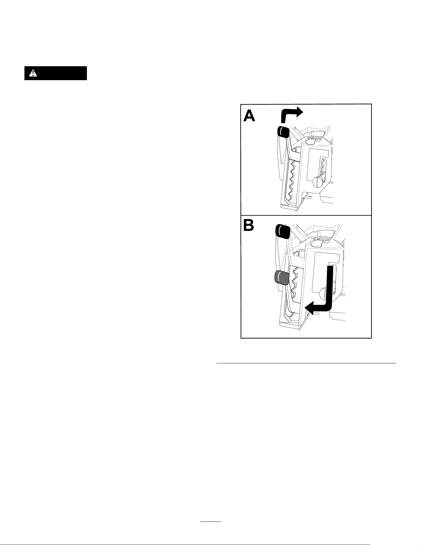
PushingtheMachineby
Hand
Thismachinehasanelectric-brakemechanism,
andtopushthemachine,thekeymustbeinthe
RUNposition.Thebatteryneedstobechargedand
functioningtodisengagetheelectricbrake.
1.Parkthemachineonalevelsurface,disengage
theblade-controlswitch,andmovethe
motion-controlleversoutwardtothePARK
position.
2.Shutofftheengineandwaitforallmovingparts
tostopbeforeleavingtheoperatingposition.
3.Locatethebypassleversontheframeonboth
sidesoftheengine.
4.Movebothbypassleversforwardthroughthe
slottedholeanddowntolocktheminplace
(Figure27).
WARNING
Contactwithhotsurfacesmaycause
personalinjury.
Keepyourhands,feet,face,clothing
andotherbodypartsawaytheengine,
muferandotherhotsurfaces.
WARNING
Themachinecouldunintentionallymove
whilethebypassleversarelocked
forwardintheslotandinjureyouor
bystanders.
Lockthebypassleversrearwardafter
movingthemachine.
26
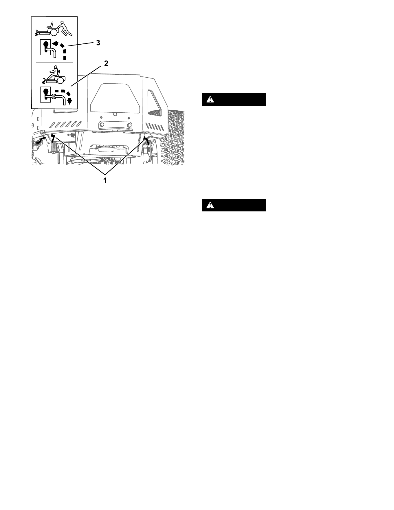
g333873
Figure27
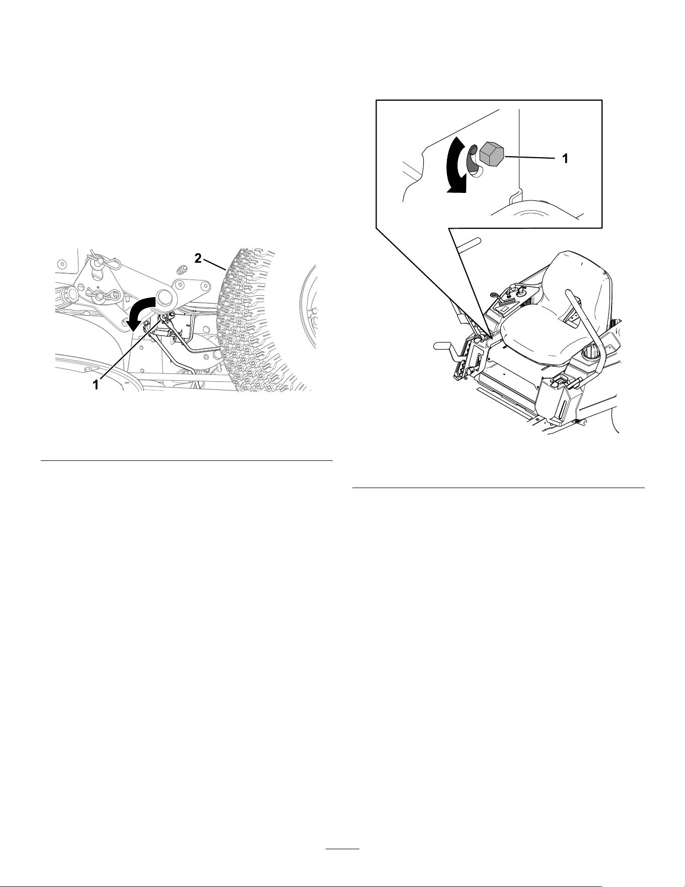
1.Bypass-leverlocations
3.Leverpositionforpushing
themachine
2.Leverpositionfor
operatingthemachine
5.TurntheignitionkeytotheRUNpositionand
disengagetheparkingbrakebymoving1
motion-controlleveroutofthePARKposition.
Note:Donotstartthemachine.
6.Movethemachineasrequired.
Important:Alwayspushthemachineby
hand.Donottowthemachine,because
towingmaydamageit.
7.Movethemotion-controlleversoutwardtothe
PARKposition.
8.TurnthekeytotheOFFpositionandremoveitto
avoiddrainingthebatterycharge.
9.Movebothbypassleversrearwardanddown
throughtheslottedholetolocktheminplace.
TransportingtheMachine
Useaheavy-dutytrailerortrucktotransportthe
machine.Useafull-widthramp.Ensurethatthetrailer
ortruckhasallthenecessarybrakes,lighting,and
markingasrequiredbylaw.Pleasecarefullyreadall
thesafetyinstructions.Knowingthisinformationcould
helpyouorbystandersavoidinjury.Refertoyour
localordinancesfortrailerandtie-downrequirements.
WARNING
Drivingonthestreetorroadwaywithout
turnsignals,lights,reectivemarkings,ora
slow-moving-vehicleemblemisdangerous
andcanleadtoaccidents,causingpersonal
injury.
Donotdrivethemachineonapublicstreet
orroadway.
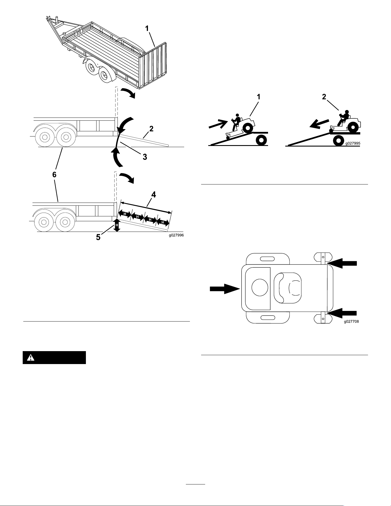
SelectingaTrailer
WARNING
Loadingamachineontoatrailerortruck
increasesthepossibilityoftip-overandcould
causeseriousinjuryordeath(Figure28).
•Useonlyafull-widthramp;donotuse
individualrampsforeachsideofthe
machine.
•Donotexceeda15-degreeanglebetween
therampandthegroundorbetweenthe
rampandthetrailerortruck.
•Ensurethatthelengthoftherampisat
least4timesaslongastheheightofthe
trailerortruckbedtotheground.This
ensuresthattherampangledoesnot
exceed15degreesonatground.
27
g027996
Figure28
1.Full-widthrampinstowed
position
4.Rampisatleast4times
aslongastheheightof
thetrailerortruckbedto
theground
2.Sideviewoffull-width
rampinloadingposition
5.H=heightofthetraileror
truckbedtotheground
3.Notgreaterthan
15degrees
6.Trailer
LoadingtheMachine
WARNING
Loadingamachineontoatrailerortruck
increasesthepossibilityoftip-overandcould
causeseriousinjuryordeath.
•Useextremecautionwhenoperatinga
machineonaramp.
•Backthemachineuptherampanddriveit
forwarddowntheramp.
•Avoidsuddenaccelerationordeceleration
whiledrivingthemachineonarampas
thiscouldcausealossofcontrolora
tip-oversituation.
1.Ifyouareusingatrailer,connectittothetowing
vehicleandconnectthesafetychains.
2.Ifapplicable,connectthetrailerbrakesand
lights.
3.Lowertheramp,ensuringthattheangle
betweentherampandthegrounddoesnot
exceed15degrees(Figure28).
4.Backthemachineuptheramp(Figure29).
g027995
Figure29
1.Backthemachineupthe
ramp.
2.Drivethemachineforward
downtheramp.
5.Shutofftheengine,removethekey,andmove
themotion-controlleversoutwardtothePARK
position.
6.Tiedownthemachinenearthefrontcaster
wheelsandtherearframewithstraps,chains,
cable,orropes(Figure30).Refertolocal
regulationsfortie-downrequirements.
g027708
Figure30
1.Tie-downpoints
UnloadingtheMachine
1.Lowertheramp,ensuringthattheangle
betweentherampandthegrounddoesnot
exceed15degrees(Figure28).
2.Drivethemachineforwarddowntheramp
(Figure29).
28

Maintenance
Note:Determinetheleftandrightsidesofthemachinefromthenormaloperatingposition.
MaintenanceSafety
•Ifyouleavethekeyintheswitch,someonecould
accidentlystarttheengineandseriouslyinjureyou
orotherbystanders.Removethekeyfromthe
switchbeforeyouperformanymaintenance.
•Beforeyouleavetheoperator’sposition,dothe
following:
–Parkthemachineonalevelsurface.
–Disengagethedrives.
–Engagetheparkingbrake.
–Shutofftheengineandremovethekey.
–Allowmachinecomponentstocoolbefore
performingmaintenance.
•Donotallowuntrainedpersonneltoservicethe
machine.
•Keepyourhandsandfeetawayfrommoving
partsorhotsurfaces.Ifpossible,donotmake
adjustmentswiththeenginerunning.
•Carefullyreleasepressurefromcomponentswith
storedenergy.
•Checktheparkingbrakeoperationfrequently.
Adjustandserviceitasrequired.
•Nevertamperwithsafetydevices.Checktheir
properoperationregularly.
•Cleangrassanddebrisfromthecuttingunit,
mufer,drives,grasscatcher,andengine
compartmenttopreventres.
•Cleanupoilorfuelspillsandremovefuel-soaked
debris.
•Donotrelyonhydraulicormechanicaljacksto
supportthemachine;supportthemachinewith
jackstandswheneveryouraisethemachine.
•Keepallpartsingoodworkingcondition
andallhardwaretightened,especiallythe
blade-attachmenthardware.Replaceallwornor
damageddecals.
•Disconnectthecablefromthenegativeterminalof
thebatterybeforerepairingthemachine.
•Toensureoptimumperformance,useonly
genuineTororeplacementpartsandaccessories.
Replacementpartsandaccessoriesmadeby
othermanufacturerscouldbedangerous,and
suchusecouldvoidtheproductwarranty.
29

RecommendedMaintenanceSchedule(s)
MaintenanceService
Interval
MaintenanceProcedure
Beforeeachuseordaily
•Checkthesafety-interlocksystem.
•Checktheengine-oillevel.
•Inspecttheblades.
•Inspectthegrassdeectorfordamage.
Aftereachuse
•Cleangrassanddebrisfromthecuttingunit,mufer,drives,grasscatcher,and
engine.
•Cleanthemower-deckhousing.
•Cleangrassanddebrisfromthecuttingunit,mufer,drives,grasscatcher,and
engine.
Every25hours
•Greasethecasterwheelbearings(moreofteninsandysoilconditions).
•Cleantheair-cleanerfoamelement(moreoftenindusty,dirtyconditions).
•Checktirepressure.
•Checkthebeltsforwearorcracks.
Every100hours
•Replacetheair-cleanerfoamelement(moreoftenindusty,dirtyconditions).
•Removeandcleantheblowerhousingandanyothercoolingshrouds(moreoften
underextremelydusty,dirtyconditions).
•Replacethein-linefuellter.
Every100hoursoryearly,
whichevercomesrst
•Replacethepaperair-cleanerelement(moreoftenindirtyordustyconditions).
•Changetheengineoilandoillter(moreoftenindirtyordustyconditions).
•Checkthesparkplug(s).
Every200hours
•Replacethesparkplug(s).
Beforestorage
•Chargethebatteryanddisconnectthebatterycables.
•Performallmaintenanceprocedureslistedabovebeforestorage.
•Paintanychippedsurfaces.
Important:Refertoyourengineowner'smanualforadditionalmaintenanceprocedures.
CAUTION
Ifyouleavethekeyintheswitch,someonecouldaccidentlystarttheengineandseriously
injureyouorotherbystanders.
Shutofftheengineandremovethekeyfromtheswitchbeforeyouperformanymaintenance.
Pre-Maintenance
Procedures
RaisingtheMachine
Usejackstandstosupportthemachinewhenyou
raiseit.
WARNING
Supportingthemachineonthelowermufer
shield(Figure31)maydamagetheshieldand
causethemachinetofall,injuringyouor
bystanders.
Donotusethelowermufershieldtoliftor
supportthemachine.
30
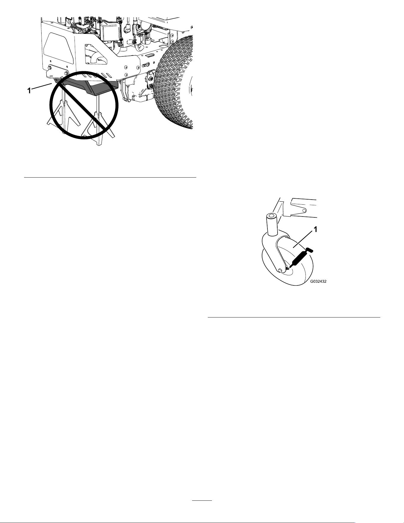
g299647
Figure31
1.Lowermufershield
Lubrication
GreasingtheBearings
ServiceInterval:Every25hours—Greasethecaster
wheelbearings(moreofteninsandy
soilconditions).
GreaseType:No.2lithiumgrease
1.Parkthemachineonalevelsurface,disengage
theblade-controlswitch,andmovethe
motion-controlleversoutwardtothePARK
position.
2.Shutofftheengine,removethekey,andwait
forallmovingpartstostopbeforeleavingthe
operatingposition.
3.Cleanthegreasettings(Figure32)witharag.
Note:Scrapeanypaintoffthefrontofthe
tting(s).
g032432
Figure32
1.Frontcastertire
4.Connectagreaseguntoeachtting(Figure32).
5.Pumpgreaseintothettingsuntilgreasebegins
tooozeoutofthebearings.
6.Wipeupanyexcessgrease.
31
EngineMaintenance
EngineSafety
•Keepyourhands,feet,face,otherbodyparts,
andclothingawayfromthemuferandotherhot
surfaces.Allowenginecomponentstocoolbefore
performingmaintenance.
•Donotchangetheenginegovernorspeedor
overspeedtheengine.
ServicingtheAirCleaner
ServiceInterval:Every25hours—Cleanthe
air-cleanerfoamelement(more
oftenindusty,dirtyconditions).
Every100hours—Replacetheair-cleanerfoam
element(moreoftenindusty,dirtyconditions).
Note:Servicetheaircleanermorefrequently(every
fewhours)ifoperatingconditionsareextremelydusty
orsandy.
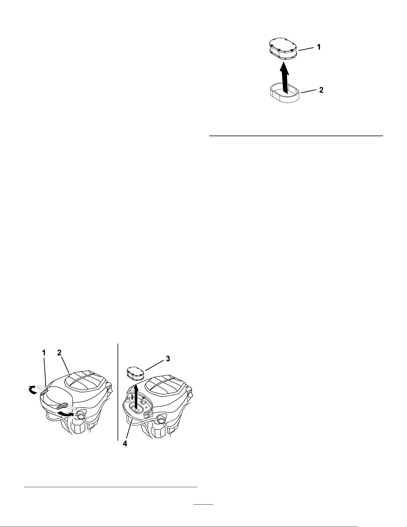
RemovingtheFoamandPaper
Elements
1.Parkthemachineonalevelsurface,disengage
theblade-controlswitch,andmovethe
motion-controlleversoutwardtothePARK
position.
2.Shutofftheengine,removethekey,andwait
forallmovingpartstostopbeforeleavingthe
operatingposition.
3.Cleanaroundtheair-cleanercovertoprevent
dirtfromgettingintotheengineandcausing
damage.
4.Rotatethelatchesoutwardandremovethe
covertoaccesstheair-cleanerelements.
g333875
Figure33
1.Latch3.Air-cleanerelements
2.Engine4.Air-cleanerbase
5.Separatethefoamandpaperelements(Figure
34).
g333887
Figure34
1.Paperelement2.Foamelement
ServicingtheFoamElement
1.Washthefoamelementinliquidsoapand
warmwater.Whentheelementisclean,rinse
itthoroughly.
2.Drytheelementbysqueezingitinacleancloth.
Important:Replacethefoamelementifit
istornorworn.
3.Lightlyoilthefoamelementusingnewengineoil
andsqueezeoutanyexcessoil.
32

ServicingthePaperAir-Cleaner
Element
ServiceInterval:Every100hoursoryearly,
whichevercomesrst—Replacethe
paperair-cleanerelement(more
oftenindirtyordustyconditions).
1.Cleanthepaperelementbytappingitgentlyto
removedust.
Note:Ifitisverydirty,replacethepaper
elementwithanewone.
2.Inspecttheelementfortears,anoilylm,or
damagetotherubberseal.
3.Replacethepaperelementifitisdamaged.
Important:Donotcleanthepaperlter.
InstallingtheAirCleaner
1.Installthefoampre-cleanerelementoverthe
paperelement.
Note:Ensurethatyoudonotdamagethe
elements.
2.Installtheair-cleanerelementsontothe
air-cleanerbase.
3.Installthecoverandsecureitwiththelatches
(Figure33).
ServicingtheEngineOil
Engine-OilSpecications
OilType:Detergentoil(includingsynthetic)ofAPI
serviceSJorhigher
CrankcaseCapacity:1.9L(64oz)withoillter
Viscosity:Seethetablebelow.
g017552
Figure35
CheckingtheEngine-OilLevel
ServiceInterval:Beforeeachuseordaily
Note:Checktheoilwhentheengineiscold.
Important:Ifyouoverllorunderlltheengine
crankcasewithoilandruntheengine,youmay
damagetheengine.
1.Parkthemachineonalevelsurface,disengage
theblade-controlswitch,andmovethe
motion-controlleversoutwardtothePARK
position.
2.Shutofftheengine,removethekey,andwait
forallmovingpartstostopbeforeleavingthe
operatingposition.
Note:Ensurethattheengineiscoolsothatthe
oilhashadtimetodrainintothesump.
3.Tokeepdirt,grassclippings,etc.,outofthe
engine,cleantheareaaroundtheoil-llcapand
dipstickbeforeremovingit(Figure36).
g365791
Figure36
33
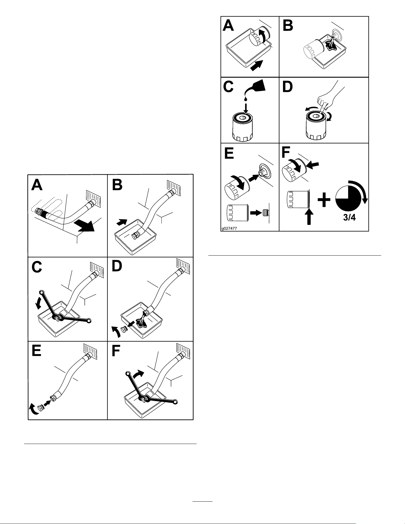
ChangingtheEngineOilandOil
Filter
ServiceInterval:Every100hoursoryearly,
whichevercomesrst—Changethe
engineoilandoillter(moreoften
indirtyordustyconditions).
1.Parkthemachineonalevelsurfacetoensure
thattheoildrainscompletely.
2.Parkthemachineonalevelsurface,disengage
theblade-controlswitch,andmovethe
motion-controlleversoutwardtothePARK
position.
3.Shutofftheengine,removethekey,andwait
forallmovingpartstostopbeforeleavingthe
operatingposition.
4.Draintheoilfromtheengine(Figure37).
g225280
Figure37
5.Changetheengine-oillter(Figure38).
Note:Ensurethattheoil-ltergaskettouches
theengineandthenturnthelteranextra3/4
turn.
g027477
Figure38
6.Slowlypourapproximately80%ofthespecied
oilintothellertubeandslowlyaddthe
additionaloiltobringittotheFullmark(Figure
39).
34
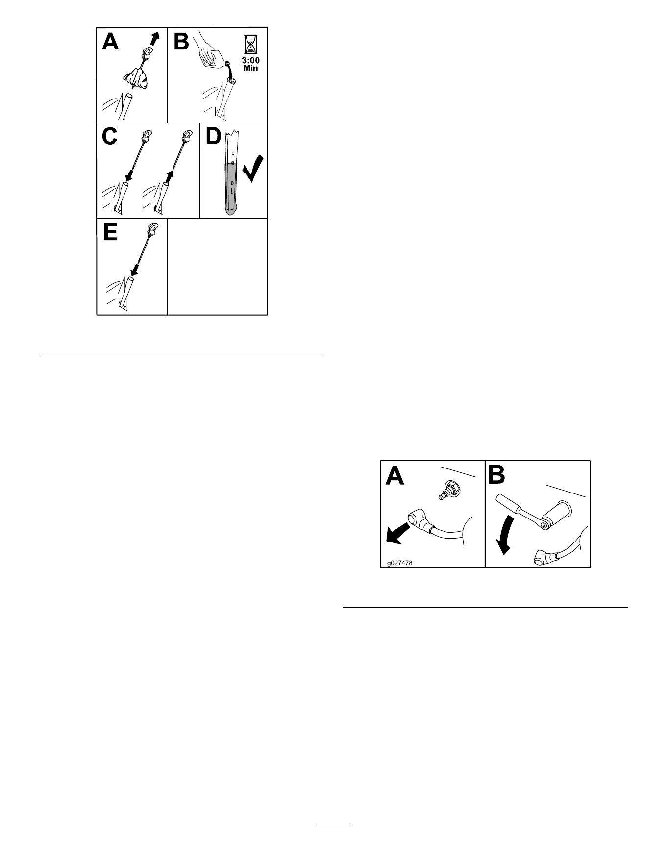
g365790
Figure39
7.Disposeoftheusedoilatarecyclingcenter.
ServicingtheSparkPlug
ServiceInterval:Every100hoursoryearly,
whichevercomesrst—Checkthe
sparkplug(s).
Every200hours/Every2years(whichever
comesrst)—Replacethesparkplug(s).
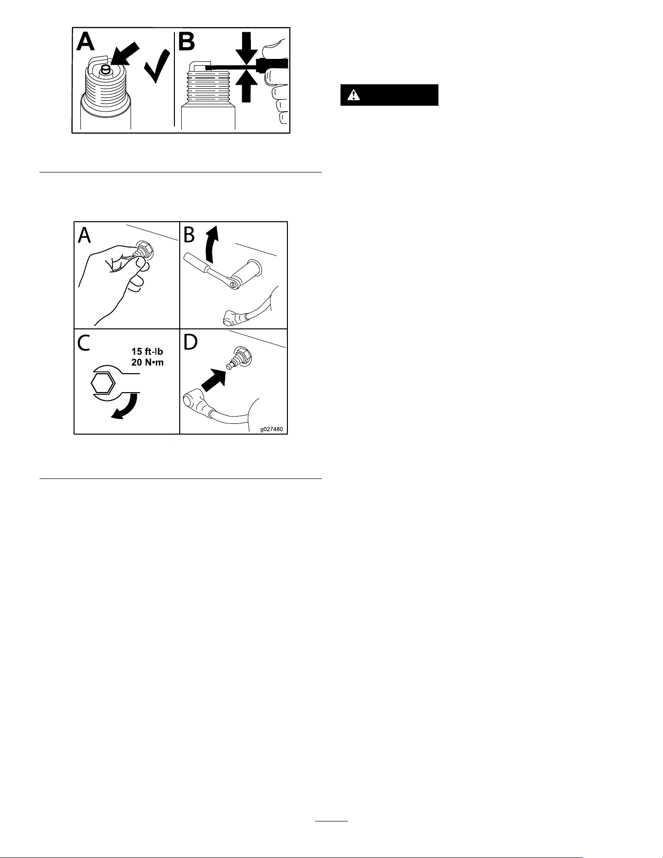
Ensurethattheairgapbetweenthecenterandside
electrodesiscorrectbeforeinstallingthesparkplug.
Useasparkplugwrenchforremovingandinstalling
thesparkplugandagappingtoolorfeelergaugeto
checkandadjusttheairgap.Installanewsparkplug
ifnecessary.
Type:Champion
®
XC12YC
Airgap:0.76mm(0.03inch)
RemovingtheSparkPlug
1.Parkthemachineonalevelsurface,disengage
theblade-controlswitch,andmovethe
motion-controlleversoutwardtothePARK
position.
2.Shutofftheengine,removethekey,andwait
forallmovingpartstostopbeforeleavingthe
operatingposition.Allowtheenginetocool.
3.Cleantheareaaroundthebaseoftheplugto
keepdirtanddebrisoutoftheengine.
4.Removethesparkplug(Figure40).
g027478
Figure40
CheckingtheSparkPlug
Important:Donotcleanthesparkplug(s).
Alwaysreplacethesparkplug(s)whenithasa
blackcoating,wornelectrodes,anoilylm,or
cracks.
Ifyouseelightbrownorgrayontheinsulator,the
engineisoperatingproperly.Ablackcoatingonthe
insulatorusuallymeanstheaircleanerisdirty.
Setthegapto0.75mm(0.03inch).
35
g206628
Figure41
InstallingtheSparkPlug
g027480
Figure42
CleaningtheBlower
Housing
ServiceInterval:Every100hours/Yearly(whichever
comesrst)
Toensurepropercooling,ensurethatthegrass
screen,coolingns,andotherexternalsurfacesofthe
enginearekeptcleanatalltimes.
Cleanthecoolingnsandexternalsurfacesas
necessary.Makesurethatthecoolingshroudsare
installed.T orquetheblowerhousingscrewsto7.5
N∙m(5.5ft-lb).
Important:Operatingtheenginewithablocked
grassscreen,dirtyorpluggedcoolingns,and/or
coolingshroudsremoved,causesenginedamage
duetooverheating.
FuelSystem
Maintenance
DANGER
Incertainconditions,fuelisextremely
ammableandhighlyexplosive.Areor
explosionfromfuelcanburnyouandothers
andcandamageproperty.
RefertoFuelSafety(page14)foracomplete
listoffuelrelatedprecautions.
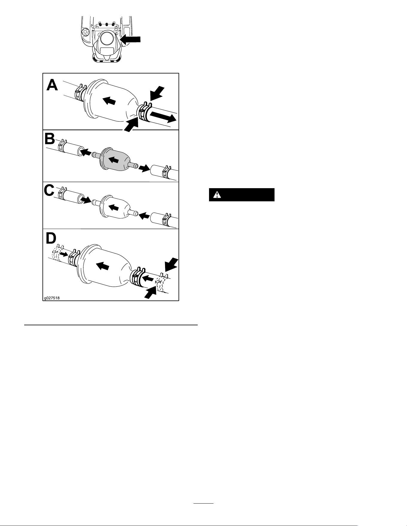
ReplacingtheIn-LineFuel
Filter
ServiceInterval:Every100hours—Replacethe
in-linefuellter.
Neverinstalladirtylterafterremovingitfromthe
fuelline.
1.Parkthemachineonalevelsurface,disengage
theblade-controlswitch,andmovethe
motion-controlleversoutwardtothePARK
position.
2.Shutofftheengine,removethekey,andwait
forallmovingpartstostopbeforeleavingthe
operatingposition.Allowtheenginetocool.
3.Replacethelter(Figure43).
Note:Ensurethattheow-directionarrowon
thereplacementlterpointstowardtheengine.
36
g365941
g027518
Figure43
ElectricalSystem
Maintenance
ElectricalSystemSafety
•Disconnectthecablefromthenegativeterminalof
thebatterybeforerepairingthemachine.
•Chargethebatteryinanopen,well-ventilated
area,awayfromsparksandames.Unplugthe
chargerbeforeconnectingordisconnectingthe
battery.Wearprotectiveclothinganduseinsulated
tools.
ServicingtheBattery
RemovingtheBattery
WARNING
Batteryterminalsormetaltoolscouldshort
againstmetalmachinecomponents,causing
sparks.Sparkscancausethebatterygasses
toexplode,resultinginpersonalinjury.
•Whenremovingorinstallingthebattery,
donotallowthebatteryterminalstotouch
anymetalpartsofthemachine.
•Donotallowmetaltoolstoshortbetween
thebatteryterminalsandmetalpartsofthe
machine.
1.Parkthemachineonalevelsurface,disengage
theblade-controlswitch,andmovethe
motion-controlleversoutwardtothePARK
position.
2.Shutofftheengine,removethekey,andwait
forallmovingpartstostopbeforeleavingthe
operatingposition.
3.Raisetheseattoaccessthebattery.
4.Disconnectthenegative(black)groundcable
fromthebatterypost(Figure44).
Note:Retainallfasteners.
37
WARNING
Incorrectlyremovingthecablesfrom
batterycoulddamagethemachineand
cables,causingsparks.Sparkscan
causethebatterygassestoexplode,
resultinginpersonalinjury.
•Alwaysdisconnectthenegative
(black)batterycablebefore
disconnectingthepositive(red)
cable.
•Alwaysconnectthepositive(red)
batterycablebeforeconnectingthe
negative(black)cable.
5.Slidetherubbercoveroffthepositive(red)
cable.
6.Disconnectthepositive(red)cablefromthe
batterypost(Figure44).
Note:Retainallfasteners.
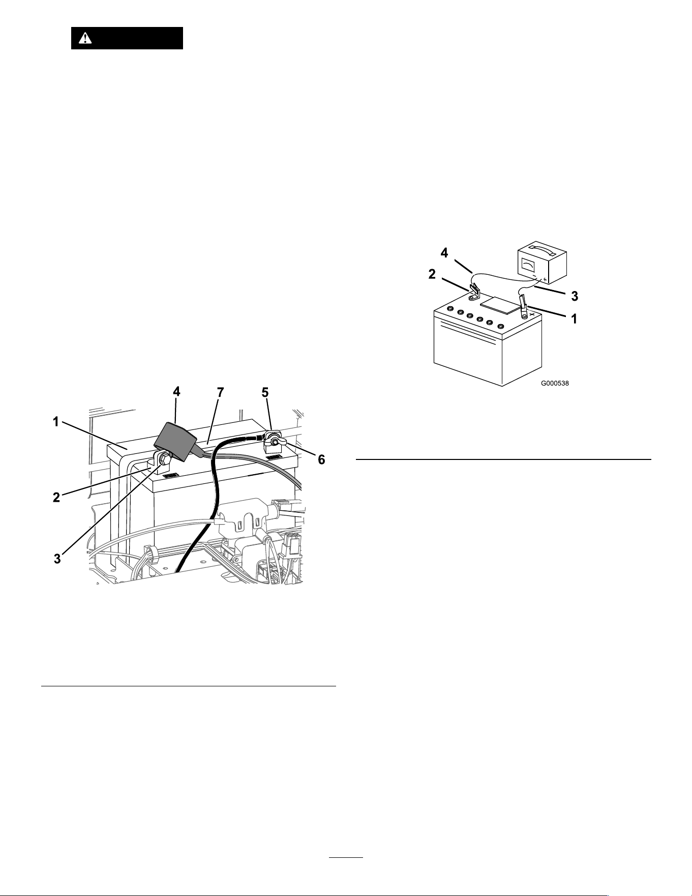
7.Removethebatteryhold-down(Figure44),and
liftthebatteryfromthebatterytray.
g293472
Figure44
1.Battery
5.Negative(–)batterypost
2.Positive(+)batterypost
6.Wingnut,washer,andbolt
3.Bolt,washer,andnut7.Batteryhold-down
4.Terminalboot
ChargingtheBattery
ServiceInterval:Beforestorage—Chargethebattery
anddisconnectthebatterycables.
1.Removethebatteryfromthechassis;referto
RemovingtheBattery(page37).
2.Chargethebatteryforaminimumof1hourat
6to10A.
Note:Donotoverchargethebattery.
3.Whenthebatteryisfullycharged,unplug
thechargerfromtheelectricaloutlet,then
disconnectthechargerleadsfromthebattery
posts(Figure45).
g000538
Figure45
1.Positive(+)batterypost3.Red(+)chargerlead
2.Negative(–)batterypost4.Black(–)chargerlead
InstallingtheBattery
1.Positionthebatteryinthetray(Figure44).
2.Usingthefastenerspreviouslyremoved,install
thepositive(red)batterycabletothepositive
(+)batteryterminal.
3.Usingthefastenerspreviouslyremoved,install
thenegativebatterycabletothenegative(-)
batteryterminal.
4.Slidetheredterminalbootontothepositive
(red)batterypost.
5.Securethebatterywiththehold-down(Figure
44).
6.Lowertheseat.
38
ServicingtheFuses
Theelectricalsystemisprotectedbyfuses.Itrequires
nomaintenance;however,ifafuseblows,checkthe
component/circuitforamalfunctionorshort.
Fusetype:
•Main—F1(25A,blade-type)
•ChargeCircuit—F2(15A,blade-type)
1.Parkthemachineonalevelsurface,disengage
theblade-controlswitch,andmovethe
motion-controlleversoutwardtothePARK
position.
2.Shutofftheengine,removethekey,andwait
forallmovingpartstostopbeforeleavingthe
operatingposition.
3.Raisetheseattoaccessthefuses.
4.Toreplaceafuse,pulloutthefusetoremove
it(Figure46).
g293931
Figure46
1.Chargecircuit(15A)2.Main(25A)
5.Lowertheseat.
DriveSystem
Maintenance
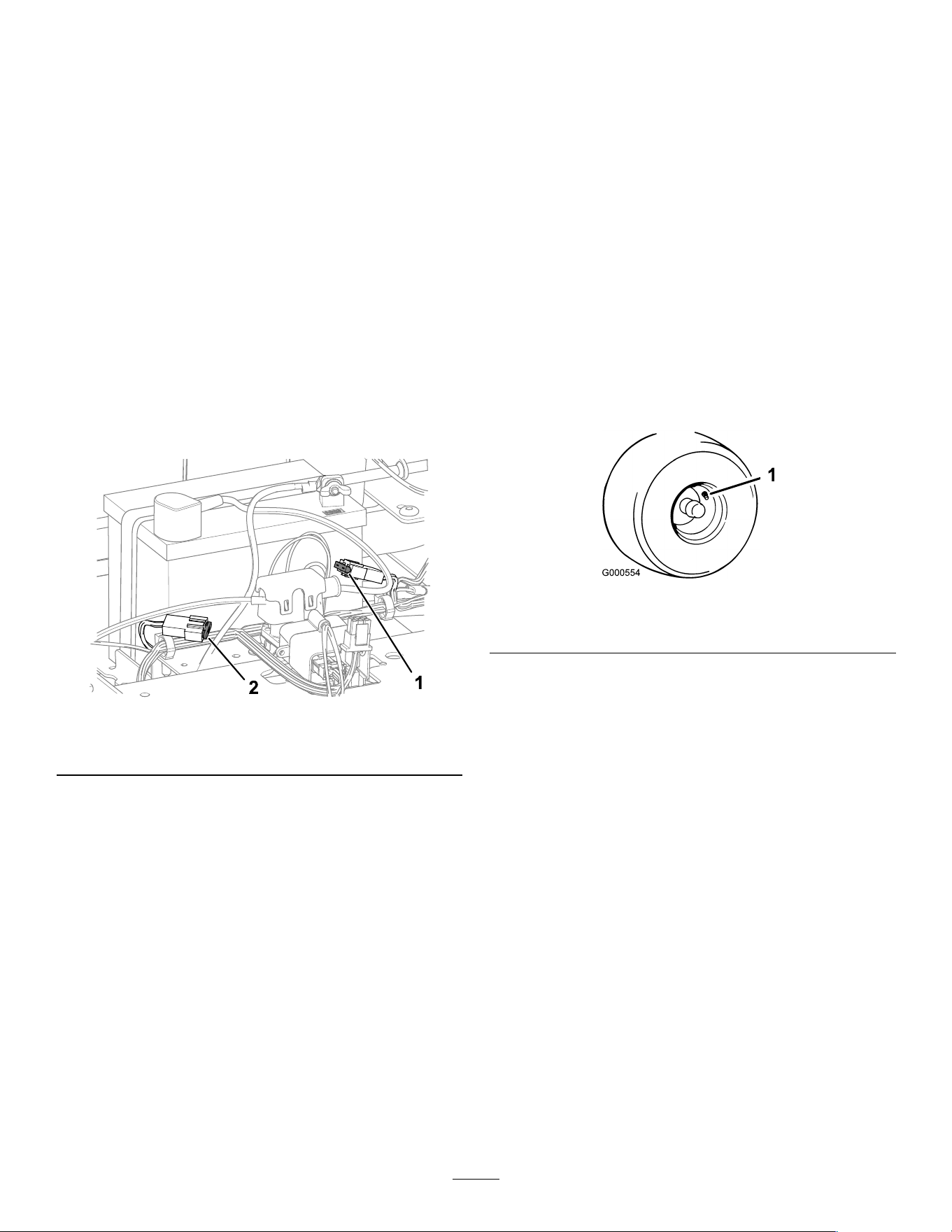
CheckingtheTirePressure
ServiceInterval:Every25hours—Checktire
pressure.
Maintaintheairpressureinthefrontandreartiresas
specied.Uneventirepressurecancauseanuneven
cut.Checkthepressureatthevalvestem(Figure47).
Checkthetireswhentheyarecoldtogetthemost
accuratepressurereading.
Inatethefrontcasterwheeltiresto206kPa(30psi)
orthepressureindicatedonthesidewall,whichever
islower.
Inatethereardrive-wheeltiresto90kPa(13psi).
g000554
Figure47
1.Valvestem
39
ReleasingtheElectric
Brake
Youcanmanuallyreleasetheelectricbrakeby
rotatingthelinkarmsforward.Oncetheelectricbrake
isenergized,thebrakeresets.
1.TurnthekeytotheOFFpositionandremove
thekey.
2.Disconnectthebattery.
3.Locatetheshaftontheelectricbrakewherethe
brakelinkarmsareconnected(Figure48).
4.Rotatetheshaftforwardtoreleasethebrake.
5.Connectthebatteryaftermovingthemachine.
g294417
Figure48
1.Brake-linkarmontheelectricbrakecontrolmodule
2.Left,reartire
AdjustingtheTracking
Whendrivingthemachineforwardfullspeedacross
aat,levelsurface,ifthemachinepullsto1side,
adjustthetracking.
Ifthemachinepullstotheleft,adjusttheright
motion-controllever;ifthemachinepullstotheright,
adjusttheleftmotion-controllever.
Note:Youcanadjustthetrackingonlyfordriving
forward.
1.Parkthemachineonalevelsurface,disengage
theblade-controlswitch,andmovethe
motion-controlleversoutwardtothePARK
position.
2.Shutofftheengine,removethekey,andwait
forallmovingpartstostopbeforeleavingthe
operatingposition.
3.Locatethetracking-adjustmentboltnearthe
motion-controlleverontheparticularsidethat
needsadjusting(Figure49).
Note:Raisetheseatforeasieraccesstothe
adjustmentbolt.
4.Rotatethebolttodecreasethespeedforthat
particularwheel.
Note:Rotatetheboltasmallamounttomake
minoradjustments.
g294926
Figure49
1.Bolt
5.Startthemachineanddriveforwardacrossa
at,levelsurfacewiththemotion-controllevers
fullyforwardtocheckifthemachinetracks
straight.Repeattheprocedureasneeded.
40
BeltMaintenance
InspectingtheBelts
ServiceInterval:Every25hours—Checkthebelts
forwearorcracks.
Replacethebeltifitisworn.Thesignsofawornbelt
includesquealingwhilethebeltisrotating;theblades
slippingwhilecuttinggrass;andfrayededges,burn
marks,andcracksonthebelt.
ReplacingtheMowerBelt
Thesignsofawornbeltincludesquealingwhilethe
beltisrotating,bladesslippingwhilecuttinggrass,
andfrayededges,burnmarks,andcracksonthebelt.
Replacethemowerbeltifanyoftheseconditionsare
evident.
1.Parkthemachineonalevelsurface,disengage
theblade-controlswitch,andmovethe
motion-controlleversoutwardtothePARK
position.
2.Shutofftheengine,removethekey,andwait
forallmovingpartstostopbeforeleavingthe
operatingposition.
3.Settheheightofcutatthelowestcuttingposition
(38mm(1-1/2inches).
4.Removethehairpincotterandpushinthetab
onthecovertoremovethepulleycovers(Figure
50).
g332328
Figure50
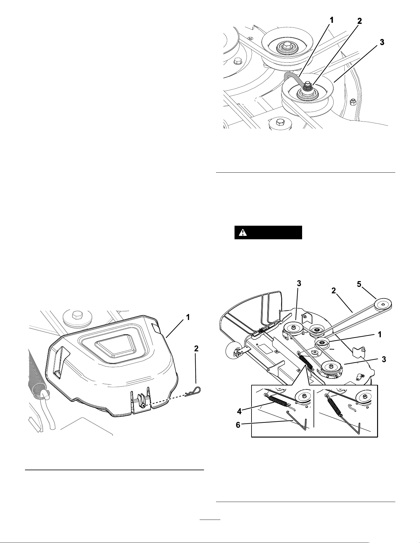
1.Cover
2.Hairpincotter
5.Fordeckswith3blades,loosenthenutsecuring
thewireformtotheidlerpulley(Figure51).
g336421
Figure51
1.Wireform
3.Idlerpulley
2.Nut
6.Usingaspring-removaltool(T oroPartNo.
92-5771),removetheidlerspringfromthedeck
hooktoremovetensionontheidlerpulley,and
rollthebeltoffthepulleys(Figure52orFigure
53).
WARNING
Thespringisundertensionwhen
installedandcancausepersonalinjury.
Becarefulwhenremovingthebelt.
g298025
Figure52
Mowerdeckswith2blades
1.Idlerpulley
4.Spring
2.Mowerbelt5.Enginepulley
3.Outsidepulley6.Spring-removaltool
41
g298026
Figure53
Mowerdeckswith3blades
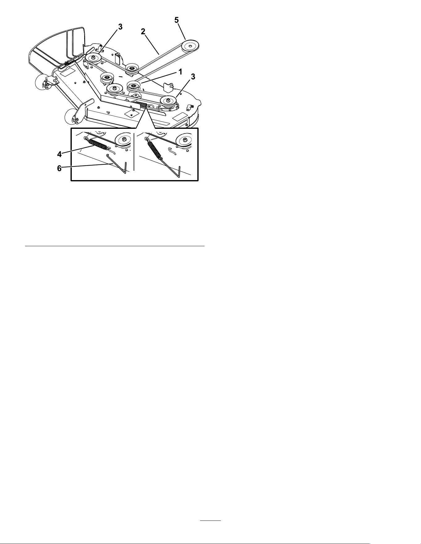
1.Idlerpulley
4.Spring
2.Mowerbelt
5.Enginepulley
3.Outsidepulley6.Spring-removaltool
7.Routethenewbeltaroundtheenginepulleyand
mowerpulleys(Figure52orFigure53).
8.Usingaspring-removaltool(T oroPartNo.
92-5771),installtheidlerspringoverthedeck
hookandplacetensionontheidlerpulleyand
themowerbelt(Figure52orFigure53).
9.Fordeckswith3blades,tightenthenutsecuring
thewireformtotheidlerpulley.
Note:Positionthewireformagainsttheidler
armasshowninFigure51.
10.Installthepulleycovers.
MowerMaintenance
BladeSafety
•Inspectthebladesperiodicallyforwearordamage.
•Usecarewhencheckingtheblades.Wrapthe
bladesorweargloves,andusecautionwhen
servicingtheblades.Onlyreplaceorsharpenthe
blades;neverstraightenorweldthem.
•Onmulti-bladedmachines,takecareasrotating
onebladecancauseotherbladestorotate.
•Replacewornordamagedbladesandboltsinsets
topreservebalance.
ServicingtheCutting
Blades
Toensureasuperiorqualityofcut,keeptheblades
sharp.Forconvenientsharpeningandreplacement,
keepextrabladesonhand.
BeforeInspectingorServicingthe
Blades
1.Parkthemachineonalevelsurface,disengage
theblade-controlswitch,andmovethe
motion-controlleversoutwardtothePARK
position.
2.Shutofftheengine,removethekey,and
disconnectthespark-plugwiresfromthespark
plugs.
InspectingtheBlades
ServiceInterval:Beforeeachuseordaily
1.Inspectthecuttingedges(Figure54).
2.Iftheedgesarenotsharporhavenicks,remove
andsharpentheblade;refertoSharpeningthe
Blades(page44).
3.Inspecttheblades,especiallyinthecurvedarea.
4.Ifyounoticeanycracks,wear,oraslotforming
inthisarea,immediatelyinstallanewblade
(Figure54).
42
g006530
Figure54
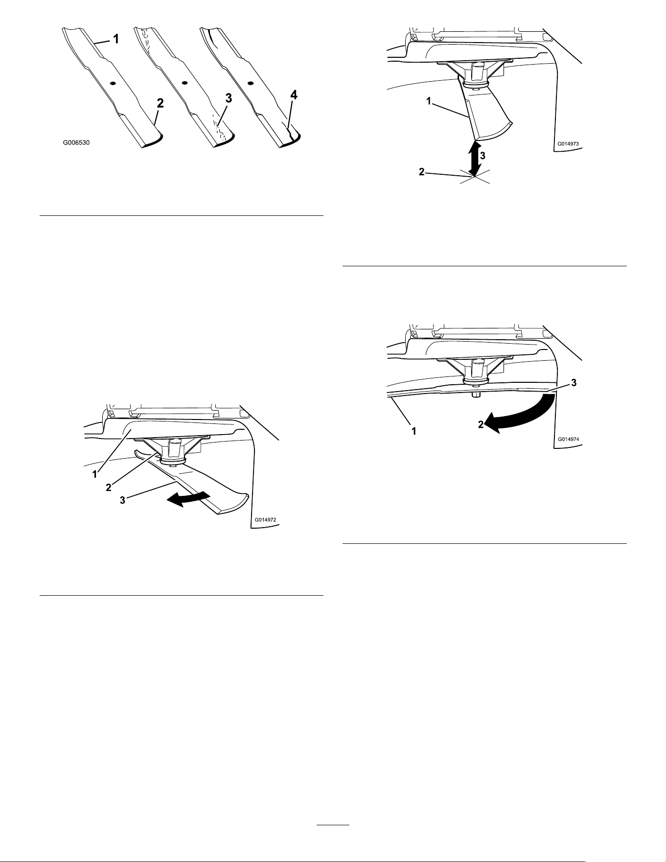
1.Cuttingedge3.Wear/slotforming
2.Curvedarea4.Crack
CheckingforBentBlades
Note:Themachinemustbeonalevelsurfacefor
thefollowingprocedure.
1.Raisethemowerdecktothehighest
height-of-cutposition.
2.Whilewearingthicklypaddedgloves,orother
adequatehandprotection,slowlyrotatethe
bladeintoapositionthatallowsyoutomeasure
thedistancebetweenthecuttingedgeandthe
levelsurfacethemachineison(Figure55).
g014972
Figure55
1.Deck3.Blade
2.Spindlehousing
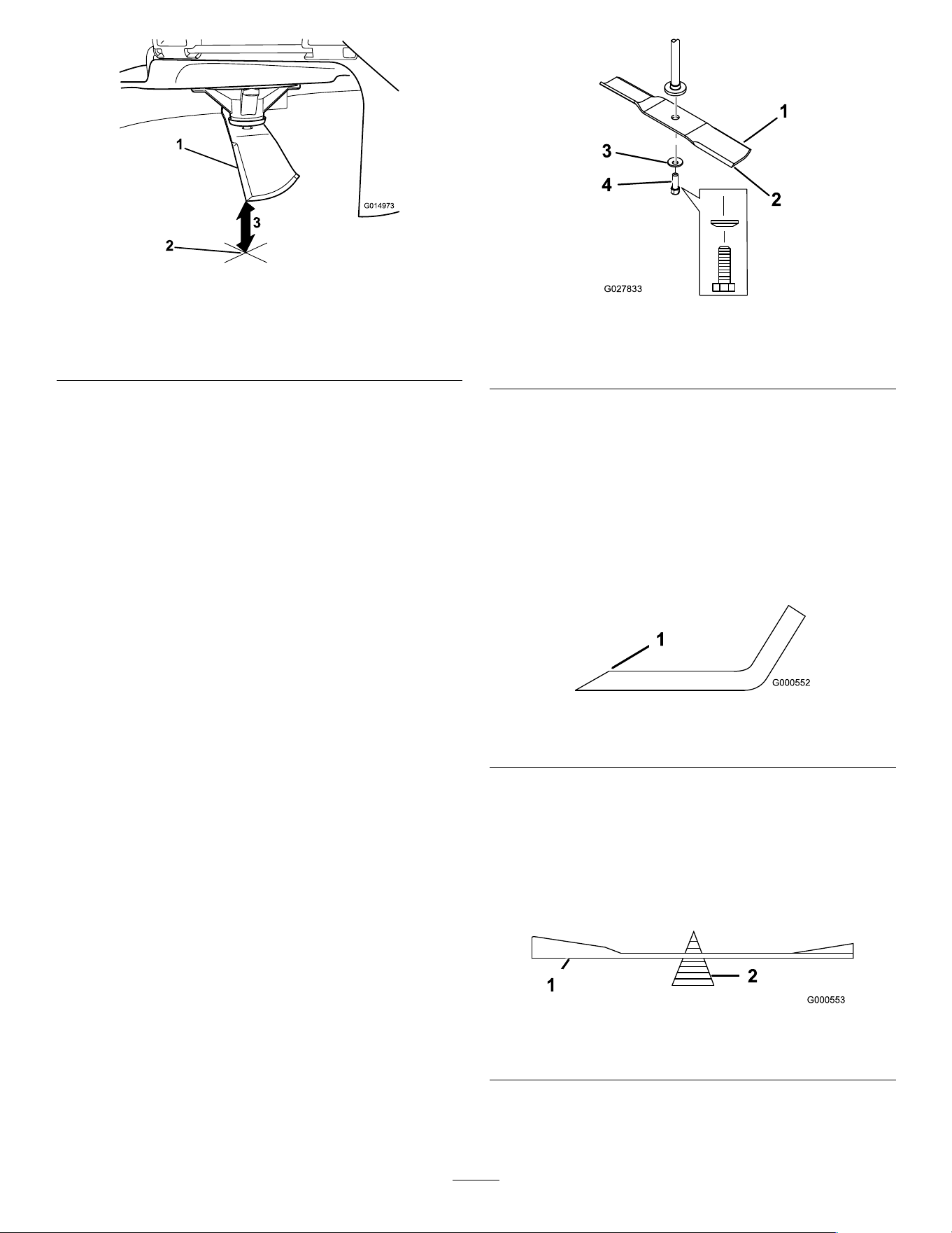
3.Measurefromthetipofthebladetotheat
surface(Figure56).
g014973
Figure56
1.Blade(inpositionformeasuring)
2.Levelsurface
3.Measureddistancebetweenbladeandthesurface(A)
4.Rotatethesameblade180degreessothat
theopposingcuttingedgeisnowinthesame
position(Figure57).
g014974
Figure57
1.Blade(sidepreviouslymeasured)
2.Measurement(positionusedpreviously)
3.Opposingsideofbladebeingmovedintomeasurement
position
5.Measurefromthetipofthebladetotheat
surface(Figure58).
Note:Thevarianceshouldbenomorethan
3mm(1/8inch).
43
g014973
Figure58
1.Oppositebladeedge(inpositionformeasuring)
2.Levelsurface
3.Secondmeasureddistancebetweenbladeandsurface(B)
A.IfthedifferencebetweenAandBisgreater
than3mm(1/8inch),replacethebladewith
anewblade;refertoRemovingtheBlades
(page44)andInstallingtheBlades(page
45).
Note:Ifabentbladeisreplacedwitha
newblade,andthedimensionobtained
continuestoexceed3mm(1/8inch),the
bladespindlecouldbebent.Contactan
AuthorizedServiceDealerforservice.
B.Ifthevarianceiswithinconstraints,moveto
thenextblade.
6.Repeatthisprocedureoneachblade.
RemovingtheBlades
Replacethebladesiftheyhitasolidobject,orifthe
bladeisoutofbalanceorbent.
1.Holdthebladeendusingaragorthicklypadded
glove.
2.Removethebladebolt,curvedwasher,and
bladefromthespindleshaft(Figure59).
g027833
Figure59
1.Sailareaoftheblade3.Curvedwasher
2.Blade4.Bladebolt
SharpeningtheBlades
1.Usealetosharpenthecuttingedgeatboth
endsoftheblade(Figure60).
Note:Maintaintheoriginalangle.
Note:Thebladeretainsitsbalanceifthesame
amountofmaterialisremovedfrombothcutting
edges.
g000552
Figure60
1.Sharpenatoriginalangle.
2.Checkthebalanceofthebladebyputtingitona
bladebalancer(Figure61).
Note:Ifthebladestaysinahorizontalposition,
thebladeisbalancedandcanbeused.
Note:Ifthebladeisnotbalanced,lesome
metalofftheendofthesailareaonly(Figure60).
g000553
Figure61
1.Blade2.Balancer
3.Repeatthisprocedureuntilthebladeis
balanced.
44
InstallingtheBlades
1.Installthebladeontothespindleshaft(Figure
59).
Important:Thecurvedpartoftheblade
mustbepointingupwardtowardtheinside
ofthemowertoensurepropercutting.
2.Installthecurvedwasher(cuppedsidetoward
theblade)andthebladebolt(Figure59).
3.Torquethebladeboltto81to108N∙m(60to
80ft-lb).
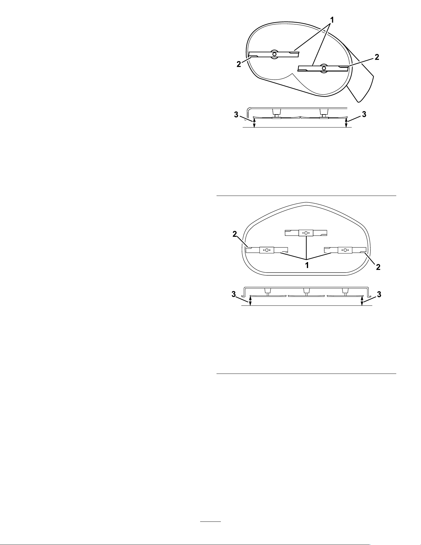
LevelingtheMowerDeck
Checktoensurethatthemowerdeckislevelanytime
youinstallthemowerorwhenyouseeanunevencut
onyourlawn.
Checkthemowerdeckforbentbladespriorto
leveling,andremoveandreplaceanybentblades;
refertotheServicingtheCuttingBlades(page42)
beforecontinuing.
Levelthemowerdeckside-to-siderst;thenyoucan
adjustthefront-to-rearslope.
Requirements:
•Themachinemustbeonalevelsurface.
•Alltiresmustbeproperlyinated;refertoChecking
theTirePressure(page39).
CheckingtheSide-to-SideLevel
1.Parkthemachineonalevelsurface,disengage
theblade-controlswitch(PTO),andmovethe
motion-controlleversoutwardtothePARK
position.
2.Shutofftheengine,removethekey,andwait
forallmovingpartstostopbeforeleavingthe
operatingposition.
3.Settheheightofcutto76mm(3inches).
4.Carefullyrotatethebladessidetoside.
5.Measurebetweentheoutsidecuttingedgesand
theatsurface(Figure62andFigure63).
Note:Ifbothmeasurementsarenotwithin5
mm(3/16inch),anadjustmentisrequired;refer
toLevelingfromSidetoSide(page46).
g294044
Figure62
MowerDeckswith2Blades
1.Bladessidetoside
3.Measurefromthetipofthe
bladetotheatsurface
here.
2.Outsidecuttingedges
g296913
Figure63
MowerDeckswith3Blades
1.Bladessidetoside
3.Measurefromthetipofthe
bladetotheatsurface
here.
2.Outsidecuttingedges
CheckingtheFront-to-RearBlade
Slope
Checkthefront-to-rearbladelevelanytimeyouinstall
themower.Ifthefrontofthemowerismorethan
7.9mm(5/16inch)lowerthantherearofthemower,
adjustthebladelevel.
1.Parkthemachineonalevelsurface,disengage
theblade-controlswitch(PTO),andmovethe
motion-controlleversoutwardtothePARK
position.
45
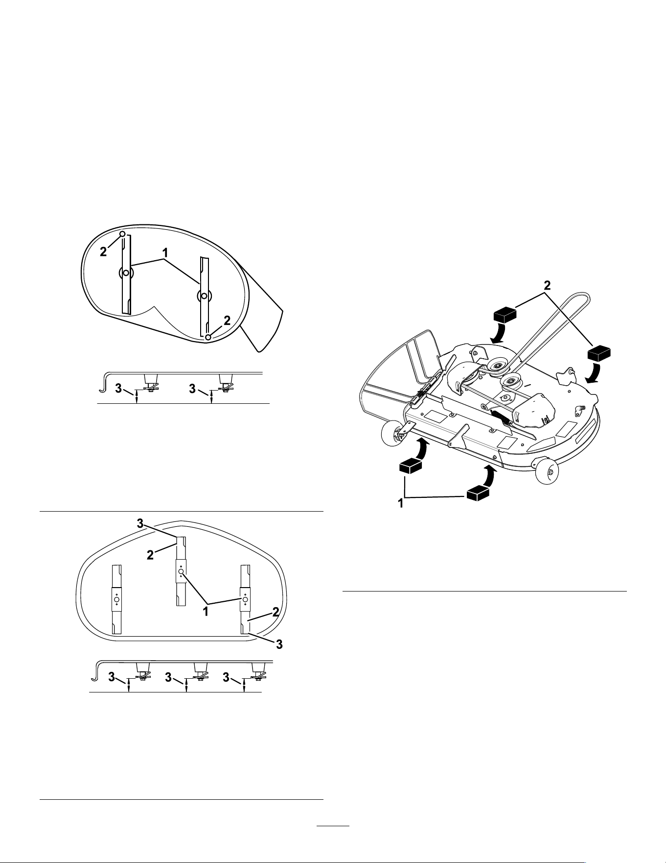
2.Shutofftheengine,removethekey,andwait
forallmovingpartstostopbeforeleavingthe
operatingposition.
3.Settheheightofcutto76mm(3inches).
4.Carefullyrotatethebladessotheyarefacing
fronttorear(Figure64).
5.Measurefromthetipofthefrontbladetotheat
surfaceandthetipoftherearbladetotheat
surface(Figure64orFigure65).
Note:Ifthefrontbladetipisnot1.6to7.9mm
(1/16to5/16inch)lowerthantherearblade
tip,continuetotheAdjustingtheFront-to-Rear
BladeSlope(page47)procedure.
g294046
Figure64
MowerDeckswith2Blades
1.Bladesfronttorear3.Measurefromthetipofthe
bladetotheatsurface
here.
2.Outsidecuttingedges
g296914
Figure65
MowerDeckswith3Blades
1.Bladesfronttorear3.Measurefromthetipofthe
bladetotheatsurface
here.
2.Outsidecuttingedges
LevelingfromSidetoSide
1.Movetotheleftsideofthemachine.
2.Settheanti-scalprollerstothetopholesor
removethemcompletelyforthisprocedure;refer
toAdjustingtheAnti-ScalpRollers(page24).
3.Settheheight-of-cutlevertothe76mm(3inch)
position;refertoAdjustingtheHeightofCut
(page23).
4.Place2blocks,eachhavingathicknessof6.6
cm(2-5/8inches),undereachsideofthefront
edgeofthedeckbutnotundertheanti-scalp
rollerbrackets(Figure66orFigure67).
5.Place2blocks,eachhavingathicknessof7.3
cm(2-7/8inches),undertherearedgeofthe
cuttingdeckskirt,1oneachsideofthecutting
deck(Figure66orFigure67).
g298027
Figure66
MowerDeckswith2Blades
1.Woodblock—6.6cm
(2-5/8inches)thick
2.Woodblock—7.3cm
(2-7/8inches)thick
46
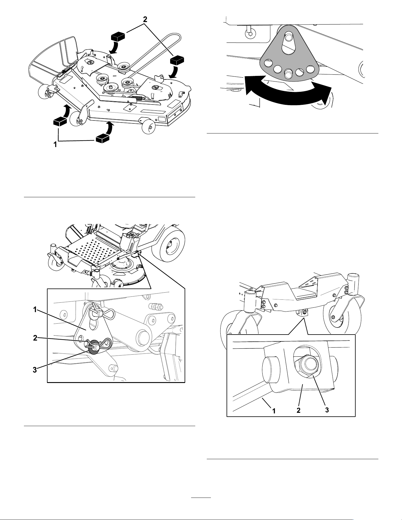
g298028
Figure67
MowerDeckswith3Blades
1.Woodblock—6.6cm
(2-5/8inches)thick
2.Woodblock—7.3cm
(2-7/8inches)thick
6.Removethehairpincotterandwasherfromthe
lowerlift-armpin(Figure68).
g294197
Figure68
1.Height-of-cutplate
3.Washer
2.Hairpincotter
7.Rotatetheheight-of-cutplatetoadifferenthole
sothatitsupportstheweightofthemowerdeck
afteryouinstalltheplate(Figure69).
g294195
Figure69
8.Installthewasherandhairpincotter(Figure69).
9.Repeatsteps6through8fortheothersideof
themachine.
10.Checktheside-to-sidelevelagain;repeatthis
procedureuntilthemeasurementsarecorrect.
11.Continuelevelingthemowerdeckbychecking
thefront-to-rearbladeslope;refertoChecking
theFront-to-RearBladeSlope(page45).
AdjustingtheFront-to-RearBlade
Slope
1.Rotatetheadjustmentnutinthefrontofthe
mower(Figure70).
g294471
Figure70
1.Adjustingrod3.Adjustmentnut
2.Adjustingblock
2.Toraisethefrontofthemowerdeck,tightenthe
adjustmentnut.
47
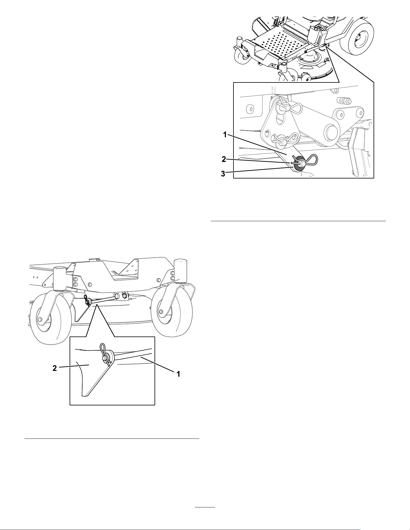
3.Tolowerthefrontofthemowerdeck,loosenthe
adjustmentnut.
4.Afteradjustment,checkthefront-to-rearslope
again,continueadjustingthenutuntilthefront
bladetipis1.6to7.9mm(1/16to5/16inch)
lowerthantherearbladetip;refertoChecking
theFront-to-RearBladeSlope(page45).
5.Whenthefront-to-rearbladeslopeiscorrect,
checktheside-to-sidelevelofthemowerdeck
again;refertoLevelingfromSidetoSide(page
46).
RemovingtheMowerDeck
1.Parkthemachineonalevelsurface,disengage
theblade-controlswitch(PTO),andmovethe
motion-controlleversoutwardtothePARK
position.
2.Shutofftheengine,removethekey,andwait
forallmovingpartstostopbeforeleavingthe
operatingposition.
3.Lowertheheight-of-cutlevertothelowest
position.
4.Removethehairpincotterfromthefrontsupport
rod,andremovetherodfromthedeckbracket
(Figure71).
g366001
Figure71
1.Frontsupportrod2.Deckbracket
5.Carefullylowerthefrontofthemowerdeckto
theground.
6.On1sideofthemachine,removethewasher
andhairpincotterfromthedeckpin(Figure72).
g295768
Figure72
1.Liftarm
3.Washer
2.Hairpincotter
7.Removetheliftarmfromthedeckpin(Figure
72).
8.Repeatsteps6and7fortheothersideofthe
machine.
9.Slidethemowerdeckrearwardtoremovethe
mowerbeltfromtheenginepulley.
10.Slidethemowerdeckoutfromunderneaththe
machine.
Note:Retainallpartsforfutureinstallation.
InstallingtheMowerDeck
1.Parkthemachineonalevelsurface,disengage
theblade-controlswitch(PTO),andmovethe
motion-controlleversoutwardtothePARK
position.
2.Shutofftheengine,removethekey,andwait
forallmovingpartstostopbeforeleavingthe
operatingposition.
3.Slidethemowerunderthemachine.
4.Lowertheheight-of-cutlevertothelowest
position.
5.On1sideofthemachine,lifttherearofthe
mowerdeckandinstalltheliftarmtothedeck
pin(Figure72).
6.Installtheliftarmusingthewasherandhairpin
cotter(Figure72).
7.Repeatsteps5and6fortheothersideofthe
machine.
48
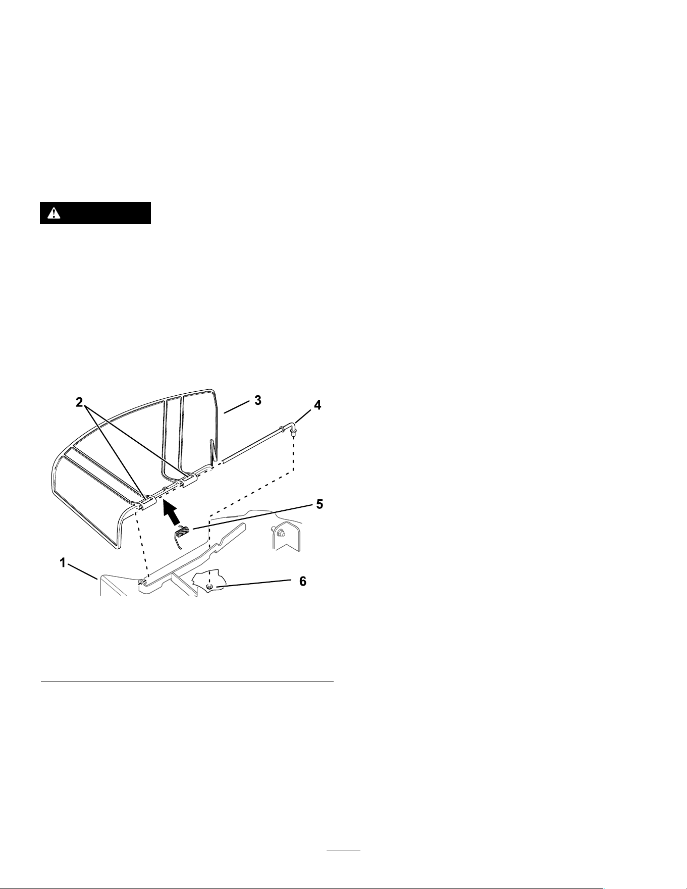
8.Attachthefrontsupportrodtothemowerdeck
withtheclevispinandhairpincotter(Figure71).
9.Installthemowerbeltontotheenginepulley;
refertoReplacingtheMowerBelt(page41).
ReplacingtheGrass
Deector
ServiceInterval:Beforeeachuseordaily—Inspect
thegrassdeectorfordamage.
WARNING
Anuncovereddischargeopeningcouldallow
themachinetothrowobjectstowardyouor
bystanders,resultinginseriousinjury.Also,
contactwiththebladecouldoccur.
Neveroperatethemachinewithoutthe
grassdeector,thedischargecover,orthe
grass-collectionsysteminplace.
1.Removethenut(3/8inch)fromtherodunder
themower(Figure73).
g296957
Figure73
1.Mowerdeck4.Rod
2.Grass-deectorpivot5.Spring
3.Grassdeector6.Nut(3/8inch)
2.Slidetherodoutofthedeckbracket,spring,and
grassdeector(Figure73).
3.Removethedamagedorworngrassdeector.
4.Installthenewgrassdeector(Figure73).
5.Slidethestraightendoftherodthroughtherear
grassdeectorpivot.
6.Placethespringontherod,withendwires
down,andbetweenthegrassdeectorbrackets.
7.Slidetherodthroughthesecondgrass-deector
pivot(Figure73).
8.Inserttherodatthefrontofthegrassdeector
intothebracketonthedeck.
9.Securetherearendoftherodintothemower
withanut(3/8inch)asshowninFigure73.
Important:Thegrassdeectormustbe
spring-loadedinthedownposition.Liftthe
deectoruptotestthatitsnapsintothe
full-downposition.
49
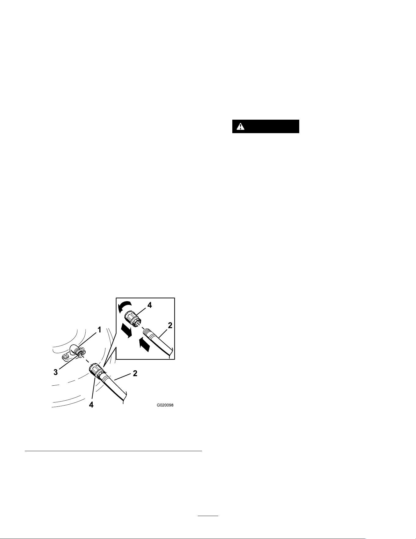
Cleaning
WashingtheUndersideof
theMowerDeck
ServiceInterval:Aftereachuse—Cleanthe
mower-deckhousing.
Important:Youcanwashthemachinewithamild
detergentandwater.Donotpressurewashthe
machine.Avoidexcessiveuseofwater,especially
nearthecontrolpanel,undertheseat,aroundthe
engine,hydraulicpumps,andmotors.
Washtheundersideofthemowerdeckaftereachuse
topreventgrassbuildupforimprovedmulchaction
andclippingdispersal.
1.Parkthemachineonalevelsurface,disengage
theblade-controlswitch(PTO),andmovethe
motion-controlleversoutwardtothePARK
position.
2.Shutofftheengine,removethekey,andwait
forallmovingpartstostopbeforeleavingthe
operatingposition.
3.Attachthehosecouplingtotheendofthe
mowerwashouttting,andturnthewateron
high(Figure74).
Note:Spreadpetroleumjellyonthewashout
ttingO-ringtomakethecouplingslideon
easierandprotecttheO-ring.
g020098
Figure74
1.Washouttting3.O-ring
2.Hose
4.Coupling
4.Lowerthemowertothelowestheight-of-cut.
5.Sitontheseatandstarttheengine.
6.Engagetheblade-controlswitchandletthe
mowerrunfor1to3minutes.
7.Disengagetheblade-controlswitch,shutoffthe
engine,removethekey,andwaitforallmoving
partstostop.
8.Turnthewateroffandremovethecouplingfrom
thewashouttting.
Note:Ifthemowerisnotcleanafter1washing,
soakitandletitstandfor30minutes.Then
repeattheprocess.
9.Runthemoweragainfor1to3minutesto
removeexcesswater.
WARNING
Abrokenormissingwashouttting
couldexposeyouandotherstothrown
objectsorbladecontact.Contactwitha
bladeorthrowndebriscancauseinjury
ordeath.
•Replacebrokenormissingwashout
ttingimmediately,beforeusing
machineagain.
•Neverputyourhandsorfeetunder
themowerorthroughopeningsinthe
machine.
DisposingofWaste
Engineoil,batteries,hydraulicuid,andengine
coolantarepollutantstotheenvironment.Disposeof
theseaccordingtoyourstateandlocalregulations.
50

Storage
StorageSafety
•Shutofftheengine,removethekey,andwait
forallmovingpartstostopbeforeyouleavethe
operator’sposition.Allowthemachinetocool
beforeadjusting,servicing,cleaning,orstoringit.
•Donotstorethemachineorfuelnearamesor
drainthefuelindoorsorinsideanenclosedtrailer.
•Donotstorethemachineorfuelcontainerwhere
thereisanopename,spark,orpilotlight,such
asonawaterheateroronotherappliances.
CleaningandStorage
1.Parkthemachineonalevelsurface,disengage
theblade-controlswitch(PTO),andmovethe
motion-controlleversoutwardtothePARK
position.
2.Shutofftheengine,removethekey,andwait
forallmovingpartstostopbeforeleavingthe
operatingposition.
3.Removegrassclippings,dirt,andgrimefromthe
externalpartsoftheentiremachine,especially
theengineandhydraulicsystem.Clean
dirtandchafffromtheoutsideoftheengine
cylinder-headnsandblowerhousing.
Important:Youcanwashthemachine
withmilddetergentandwater.Donot
pressure-washthemachine.Avoid
excessiveuseofwater,especiallynearthe
controlpanel,engine,hydraulicpumps,and
motors.
4.Checktheparkingbrakeoperation;refertoPark
Position(page12).
5.Servicetheaircleaner;refertoServicingtheAir
Cleaner(page32).
6.Greasethemachine;refertoLubrication(page
31).
7.Changethecrankcaseoil;refertoServicingthe
EngineOil(page33).
8.Checkthetirepressure;refertoCheckingthe
TirePressure(page39).
9.Chargethebattery;refertoChargingtheBattery
(page38).
10.Ifstoringthemachinewiththebatteryinstalled,
disconnectthenegative(black)cablefromthe
battery.
11.Scrapeanyheavybuildupofgrassanddirt
fromtheundersideofthemower,thenwashthe
machinewithagardenhose.
Note:Runthemachinewiththeblade-control
switch(PTO)engagedandtheengineathigh
idlefor2to5minutesafterwashing.
12.Checktheconditionoftheblades;referto
ServicingtheCuttingBlades(page42).
13.Preparethemachineforstorageforover
30daysasfollows:
A.Addfuelstabilizer/conditionertofreshfuel
inthetank.Followmixinginstructionsfrom
thefuelstabilizermanufacturer.Donot
useanalcohol-basedstabilizer(ethanolor
methanol).
B.Runtheenginetodistributeconditionedfuel
throughthefuelsystemfor5minutes.
C.Shutofftheengine,allowittocool,and
drainthefueltankusingapumptype
syphonoroperateengineuntilitshutsoff.
D.Disposeoffuelproperly.Recyclethefuel
accordingtolocalcodes.
Important:Donotstorefuelcontaining
stabilizer/conditionerlongerthan
thedurationrecommendedbythe
fuel-stabilizermanufacturer.
14.Removeandchecktheconditionofthespark
plug(s);refertoServicingtheSparkPlug(page
35).Withthesparkplug(s)removedfromthe
engine,pour30ml(2tablespoons)ofengine
oilintothesparkplughole.Usethestarterto
cranktheengineanddistributetheoilinsidethe
cylinder.Installthesparkplug(s).Donotinstall
thewireonthesparkplug(s).
15.Checkandtightenallfasteners.Repairor
replaceanypartthatisdamaged.
16.Paintallscratchedorbaremetalsurfaces.Paint
isavailablefromyourAuthorizedServiceDealer.
17.Storethemachineinaclean,drygarageor
storagearea.Removethekeyfromtheswitch
andkeepitoutofreachofchildrenorother
unauthorizedusers.Coverthemachineto
protectitandkeepitclean.
51

StoringtheBattery
1.Fullychargethebattery.
2.Letthebatteryrestfor24hours,thencheckthe
batteryvoltage.
Note:Ifthebatteryvoltageisbelow12.6V,
repeatsteps1and2.
3.Disconnectthecablesfromthebattery.
4.Checkthevoltageperiodicallytoensurethatthe
voltageis12.4Vorhigher.
Note:Ifthebatteryvoltageisbelow12.4V,
repeatsteps1and2.
BatteryStorageTips
Ifyouarestoringthebatteryoutsidethemachine,do
thefollowing:
•Storethebatteryinacool,dryareainanupright
position.
•Donotstackbatteriesdirectlyontopofeachother,
unlesstheyareincartons.
•Donotstackmorethan3batteries(only2ifthe
batterytypeiscommercial).
•Testawetbatteryevery4to6monthsandcharge
it,ifnecessary.
•Alwaystestandchargethebatterybefore
installation.
52

Troubleshooting
Problem
PossibleCauseCorrectiveAction
Thefueltankisshowingsignsofcollapsing
orthemachineisfrequentlyshowingsigns
ofrunningoutoffuel.
1.Theair-cleanerpaperelementclogged.
1.Cleanthepaperelement.
1.Theengineloadisexcessive.1.Reducethegroundspeed.
2.Theoillevelinthecrankcaseislow.2.Addoiltothecrankcase.
3.Thecoolingnsandairpassages
undertheengine-blowerhousingare
plugged.
3.Removetheobstructionfromthe
coolingnsandairpassages.
4.Theaircleanerisdirty.
4.Cleanorreplacetheair-cleaner
element.
Theengineoverheats.
5.Dirt,water,orstalefuelisinthefuel
system.
5.ContactanAuthorizedServiceDealer
1.Theblade-controlswitchisengaged.1.Disengagetheblade-controlswitch.
2.Themotion-controlleversarenotin
thePARKposition.
2.Movethemotion-controllevers
outwardtothePARKposition.
3.Thebatteryisdead.
3.Chargethebattery.
4.Theelectricalconnectionsare
corrodedorloose.
4.Checktheelectricalconnectionsfor
goodcontact.
5.Afuseisblown.5.Replacethefuse.
Thestarterdoesnotcrank.
6.Arelayorswitchisdamaged.
6.ContactanAuthorizedServiceDealer.
1.Thefueltankisempty.1.Fillthefueltank.
2.Thechoke(ifapplicable)isnoton.
2.MovethechokelevertotheON
position.
3.Theaircleanerisdirty.
3.Cleanorreplacetheair-cleaner
element.
4.Thespark-plugwire(s)islooseor
disconnected.
4.Installthewire(s)onthesparkplug.
5.Thesparkplug(s)ispitted,fouled,or
thegapisincorrect.
5.Installanew,correctlygappedspark
plug(s).
6.Thereisdirtinfuellter.6.Replacethefuellter.
7.Dirt,water,orstalefuelisinfuel
system.
7.ContactanAuthorizedServiceDealer.
8.Thereisincorrectfuelinthefueltank.
8.Drainthetankandreplacethefuelwith
thepropertype.
Theenginedoesnotstart,startshard,or
failstokeeprunning.
9.Theoillevelinthecrankcaseislow.9.Addoiltothecrankcase.
1.Theengineloadisexcessive.1.Reducethegroundspeed.
2.Theaircleanerisdirty.
2.Cleantheair-cleanerelement.
3.Theoillevelinthecrankcaseislow.3.Addoiltothecrankcase.
4.Thecoolingnsandairpassages
undertheengineblowerhousingare
plugged.
4.Removetheobstructionfromthe
coolingnsandairpassages.
5.Thesparkplug(s)ispitted,fouled,or
thegapisincorrect.
5.Installanew,correctlygappedspark
plug(s).
6.Thefuel-tankventisblocked.6.ContactanAuthorizedServiceDealer.
7.Thereisdirtinthefuellter.7.Replacethefuellter.
8.Dirt,water,orstalefuelisinthefuel
system.
8.
ContactanAuthorizedServiceDealer.
Theenginelosespower.
9.
Thereisincorrectfuelinthefueltank.
9.
ContactanAuthorizedServiceDealer.
53

Problem
PossibleCauseCorrectiveAction
1.Thebypassvalvesareopen.
1.Closethetowvalves.
2.Thetractionbeltsareworn,loose,or
broken.
2.ContactanAuthorizedServiceDealer.
3.Thetractionbeltsareoffthepulleys.3.ContactanAuthorizedServiceDealer.
Themachinedoesnotdrive.
4.Thetransmissionhasfailed.4.ContactanAuthorizedServiceDealer.
1.Thecuttingblade(s)is/arebentor
unbalanced.
1.Installnewcuttingblade(s).
2.Theblademountingboltisloose.2.Tightentheblademountingbolt.
3.Theenginemountingboltsareloose.3.Tightentheenginemountingbolts.
4.Theenginepulley,idlerpulley,orblade
pulleyisloose.
4.Tightentheappropriatepulley.
5.Theenginepulleyisdamaged.
5.ContactanAuthorizedServiceDealer.
6.Thebladespindleisbent.
6.ContactanAuthorizedServiceDealer.
Themachinevibratesabnormally.
7.Themotormountislooseorworn.
7.ContactanAuthorizedServiceDealer.
1.Theblade(s)isnotsharp.1.Sharpentheblade(s).
2.Acuttingblade(s)is/arebent.2.Installanewcuttingblade(s).
3.Themowerisnotlevel.
3.Levelthemowerfromside-to-sideand
front-to-rear.
4.Ananti-scalproller(ifapplicable)isnot
setcorrectly.
4.Adjusttheanti-scalpwheelheight.
5.Theundersideofthemowerdeckis
dirty.
5.Cleantheundersideofthemower
deck.
6.Thetirepressureisincorrect.6.Adjustthetirepressure.
Thecuttingheightisuneven.
7.Abladespindleisbent.
7.ContactanAuthorizedServiceDealer.
1.Thedrivebeltisworn,looseorbroken.1.Installanewdrivebelt.
2.Thedrivebeltisoffofthepulley.
2.Installthedrivebeltandcheckthe
adjustingshaftsandbeltguidesforthe
correctposition.
3.Thepower-takeoff(PTO)switchor
PTOclutchisfaulty.
3.ContactanAuthorizedServiceDealer.
Thebladesdonotrotate.
4.Themowerbeltisworn,loose,or
broken.
4.Installanewmowerbelt.
54
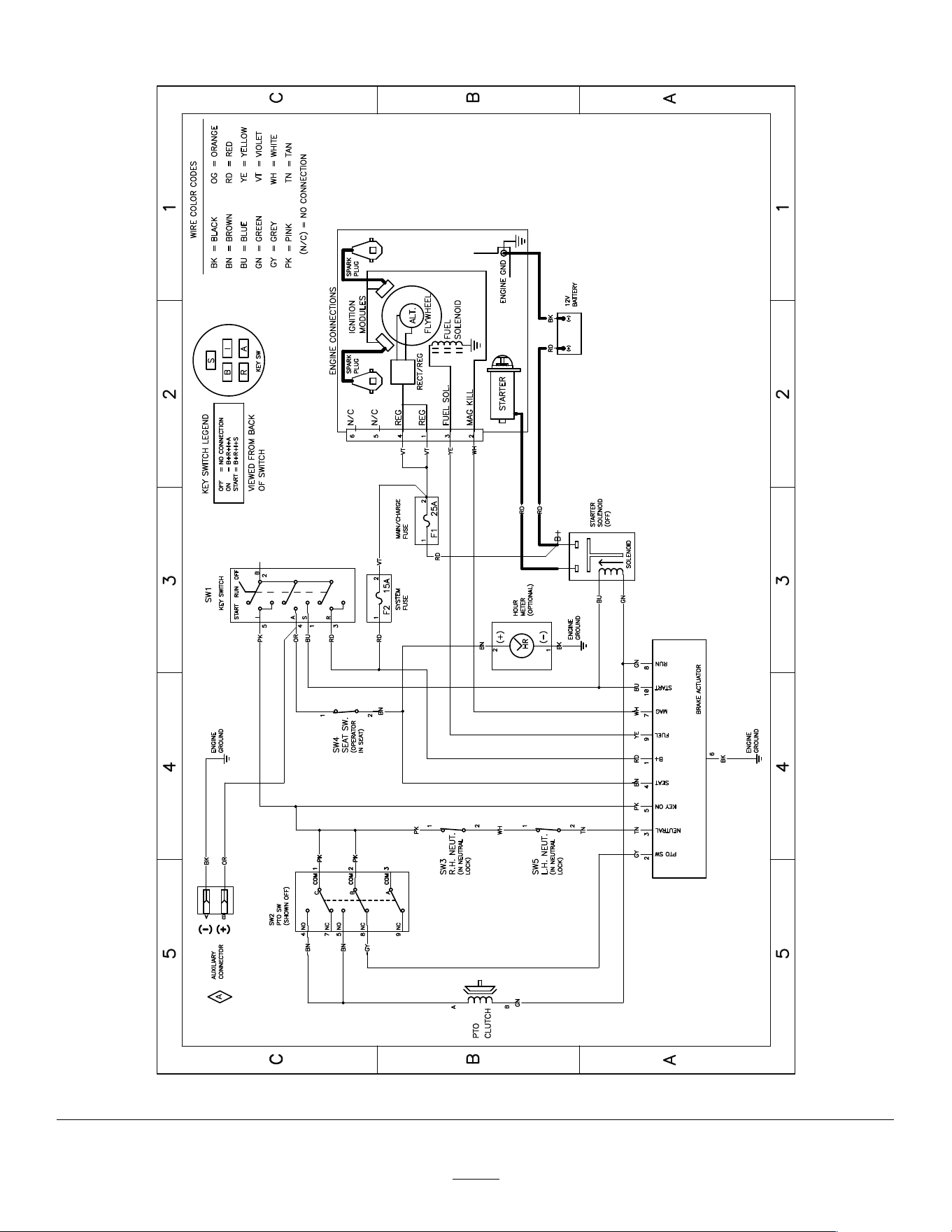
Schematics
g307974
ElectricalDiagram139-2356(Rev.A)
55

CaliforniaProposition65WarningInformation
Whatisthiswarning?
Youmayseeaproductforsalethathasawarninglabellikethefollowing:
WARNING:CancerandReproductiveHarm—www.p65Warnings.ca.gov.
WhatisProp65?
Prop65appliestoanycompanyoperatinginCalifornia,sellingproductsinCalifornia,ormanufacturingproductsthatmaybesoldinorbroughtinto
California.ItmandatesthattheGovernorofCaliforniamaintainandpublishalistofchemicalsknowntocausecancer,birthdefects,and/orother
reproductiveharm.Thelist,whichisupdatedannually,includeshundredsofchemicalsfoundinmanyeverydayitems.ThepurposeofProp65isto
informthepublicaboutexposuretothesechemicals.
Prop65doesnotbanthesaleofproductscontainingthesechemicalsbutinsteadrequireswarningsonanyproduct,productpackaging,orliteraturewith
theproduct.Moreover,aProp65warningdoesnotmeanthataproductisinviolationofanyproductsafetystandardsorrequirements.Infact,the
CaliforniagovernmenthasclariedthataProp65warning“isnotthesameasaregulatorydecisionthataproductis‘safe’or‘unsafe.’”Manyofthese
chemicalshavebeenusedineverydayproductsforyearswithoutdocumentedharm.Formoreinformation,gotohttps://oag.ca.gov/prop65/faqs-view-all
.
AProp65warningmeansthatacompanyhaseither(1)evaluatedtheexposureandhasconcludedthatitexceedsthe“nosignicantrisklevel”;or(2)
haschosentoprovideawarningbasedonitsunderstandingaboutthepresenceofalistedchemicalwithoutattemptingtoevaluatetheexposure.
Doesthislawapplyeverywhere?
Prop65warningsarerequiredunderCalifornialawonly.ThesewarningsareseenthroughoutCaliforniainawiderangeofsettings,includingbutnot
limitedtorestaurants,grocerystores,hotels,schools,andhospitals,andonawidevarietyofproducts.Additionally,someonlineandmailorder
retailersprovideProp65warningsontheirwebsitesorincatalogs.
HowdotheCaliforniawarningscomparetofederallimits?
Prop65standardsareoftenmorestringentthanfederalandinternationalstandards.TherearevarioussubstancesthatrequireaProp65warning
atlevelsthatarefarlowerthanfederalactionlimits.Forexample,theProp65standardforwarningsforleadis0.5μg/day,whichiswellbelow
thefederalandinternationalstandards.
Whydon’tallsimilarproductscarrythewarning?
•ProductssoldinCaliforniarequireProp65labellingwhilesimilarproductssoldelsewheredonot.
•AcompanyinvolvedinaProp65lawsuitreachingasettlementmayberequiredtouseProp65warningsforitsproducts,butothercompanies
makingsimilarproductsmayhavenosuchrequirement.
•TheenforcementofProp65isinconsistent.
•CompaniesmayelectnottoprovidewarningsbecausetheyconcludethattheyarenotrequiredtodosounderProp65;alackofwarningsfora
productdoesnotmeanthattheproductisfreeoflistedchemicalsatsimilarlevels.
WhydoesToroincludethiswarning?
Torohaschosentoprovideconsumerswithasmuchinformationaspossiblesothattheycanmakeinformeddecisionsabouttheproductstheybuyand
use.T oroprovideswarningsincertaincasesbasedonitsknowledgeofthepresenceofoneormorelistedchemicalswithoutevaluatingthelevelof
exposure,asnotallthelistedchemicalsprovideexposurelimitrequirements.WhiletheexposurefromT oroproductsmaybenegligibleorwellwithinthe
“nosignicantrisk”range,outofanabundanceofcaution,TorohaselectedtoprovidetheProp65warnings.Moreover,ifTorodoesnotprovidethese
warnings,itcouldbesuedbytheStateofCaliforniaorbyprivatepartiesseekingtoenforceProp65andsubjecttosubstantialpenalties.
RevA
