24709
EN
Original Instructions
Version 1
April 2024
SONIC BELT
TENSION TESTER

User Manual for: Sonic Belt Tension Tester
Stock No: 24709
Part No: ETBT
Read this manual in full before using this product and
retain it for future use. Always use the latest version of
the manual.
Please visit drapertools.com/manuals for the
latest version.
1.
– 2 –
EN
2. Product Introduction
2.1 Intended Use
This product is designed for checking the tension of all
types of drive belts including camshaft and auxiliary.
The meter can measure the vibration by using the
microphone to convert the tension level when installing
or adjusting a new belt.
Features a exible probe for restricted engine bays and
includes 20 internal memory storage slots.
This product is suitable for use by enthusiasts and
tradespersons alike. Any other application beyond the
conditions established for use will be considered misuse.
Draper Tools accepts no responsibility for improper use
of this product.
2.2 Specication
Stock No. 24709
Part No. ETBT
Frequency Range: 10- 600Hz
Battery: 2 x AAA 1.5V (not supplied)
Nett Weight: 242g
Tester Dimensions (L X W X H): 165 X 65 X 30mm
Probe Length: 115mm
Tester Probe Length: 42mm
3. Health and Safety Information
– 3 –
EN
Important: Read all the Health and Safety instructions
before attempting to operate, maintain or repair this
product. Failure to follow these instructions may result in
injury or damage to the user, the product or the vehicle.
WARNING! Risk of explosion. Do not use the
tester in an area where sparking may occur.
• ALWAYS follow the instructions and procedures listed
in the vehicle’s service manual before using this
device.
• Keep the tester in good working order and condition.
• DO NOT operate the tester with a damaged probe or it
has been dropped, get it checked by a qualied
service representative.
• DO NOT use the tester for any other purpose than
which it is designed for.
• Keep children and unauthorised person away from the
work area.
• DO NOT use whilst under the inuence of drugs,
alcohol or intoxicating medication.
• Keep the work clean and tidy and ensure adequate
lighting.
• DO NOT allow untrained persons to use the tester.
This tester should only be used by qualied personnel.
• Handle the unit with care and if dropped or showing
signs of damaged get it checked by a qualied service
person.
• Wear suitable eye and face protection.
• DO NOT put water, solvents or other liquids on the
tester.
• DO NOT leave in a dusty environment.
• Keep away from heat. DO NOT expose the tester to
strong sunlight or other heat sources.
• DO NOT pull on the probe cord.
• To prevent electric shocks, DO NOT operate outdoors
during thunderstorms.
• DO NOT bend the probe to sharp angles.
• DO NOT use this device if the tester or probe are
damaged in any way or if there is evidence of battery
leakage.
• The battery must be replaced with one with the same
specication.
• When replacing the battery check that it is tted in
the correct +/- orientation.
• Remove the battery when storing the tester for
extended periods.
• DO NOT store in a place of high temperature or
humidity.
4. Symbols
Read the instruction manual
Warning!
Do not incinerate or throw onto re
Wear face mask and safety glasses
Keep out of the reach of children
WEEE –
Waste Electrical & Electronic Equipment
Do not dispose of Waste Electrical & Electronic Equipment
in with domestic rubbish
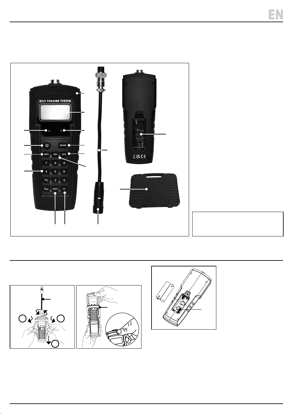
5. Identication
– 4 –
EN
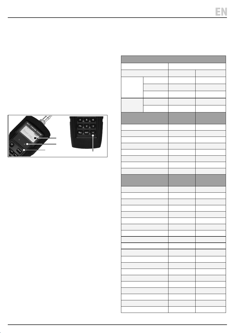
(1) Microphone
(2) Removable test probe
(3) Battery compartment
(4) Protective case
(5) LCD display screen
(6) Error red light
(7) Green indicator light
(8) Power button
(9) Measurement button
(10) Belt width button
(11) Belt mass button
(12) Belt span button
(13) Number Values 0 to 9 buttons
(14) Frequency/tension (Hz) button
(15) Select button
(16) Storage case
Please visit drapertools.com
for our full range of accessories
and consumables.
Carefully remove the product from the packaging and
examine it for any signs of damage that may have
occurred during shipment. If any part is damaged or
missing, do not attempt to use the product.
Please contact the Draper Helpline; contact details can
be found at the back of this manual.
(16)
(1)
(3)
(14)(15)
5. Battery Installation
1. To t or replace the battery, rst remove the probe (2)
and protective case (4). Fig.1 & Fig.2.
1 Fig.
2 Fig.
2. Then unclip the battery compartment (3).
Fig.3.
3 Fig.
3. Fit 2 X AAA batterie into the compartment – ensuring
that the battery is tted in the correct +/- orientation.
4. Clip the cover back on and slide the tester back in the
protective case.
• Note: Change the battery when the battery indicator
(E) shows low power on the screen.
(4)
(2)
(7)
(9)
(11)
(12)
(6)
(8)
(10)
(13)
(5)
1 2
3
(4)
(3)
(2)
6. Probe Installation 8. Operation
– 5 –
EN
4 Fig.
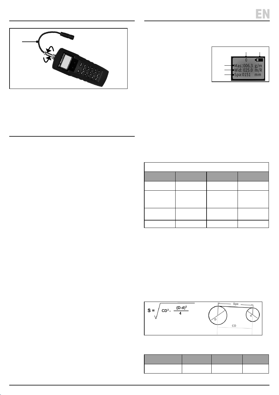
1. Connect the probe (2) to the top of the tester, then
rotate the collar clockwise until secure. Fig. 4
7. Calibration
7.1 User Calibration
1. Press the ‘POWER’ button (8) until the screen turns on.
2. Then press the ‘HZ’ button (14) to enter the frequency
measure.
3. Press the ‘MEASURE’ button (9) to enter the test
mode and check the calibration source (e.g. tuning
fork or tone generator).
4. Then press the number ‘7 & 9’ buttons at the same
time and ‘CAL’ will appear on the screen.
• For example, if using 256Hz tuning fork to calibrate,
enter value 256.0Hz and then press ‘MEASURE’
button to save the calibration.
• Note: The calibration frequency must be between
100 – 600Hz.
• ‘U’ will appear on the screen when the user calibration
is selected.
7.2 Restore Factory Calibration
1. Follow step 1 to 4 in section 7.1 Manual Calibration.
2. Then press the ‘SELECT’ button (15) to restore the
factory calibration.
7.3 Switch between User & Factory
Calibration
1. Follow step 1 to 4 in section 7.1 Manual Calibration.
2. Then press the ‘SELECT’ button (15) to restore the
factory calibration or press ‘HZ’ button (14) for user
calibration.
• Ensure the tester is calibrated before operating as per
Section 7 Calibration.
3. Press the ‘POWER’ button (8) until the screen turns on.
4. The following data will be displayed on the screen.
Fig.5
A. Mas: belt mass
B. Wid: belt width
C. Spa : tangent line span
D. No: storage number
E. Battery level
5. Enter the belt information using the relevant buttons
(10), (11) and (12). Note: The specic belt Information
can be obtained from the belt or vehicle
manufacturer’s instruction manuals.
ERROR: A red light (6) will show on the panel below the
screen if the calculated tension value is higher than the
vale displayed on the screen.
6. Press the ’SELECT’ button (15) to enter each
measurement.
Date Information
Input Data Formula Press button Value
Belt Mass Mas = XXX.X g/m ‘Mass’ (11) 000.1g to 999.9g
Width
Synchronous
Belt
Wid = XXX.X
mm/R
‘Width’ (10) 000.1 to
999.9mm
20mm = 020.0
Width
V- Belt
Enter number of
strands or ribs
‘Width (10) Number
Single = 001.0
Span Length Spa = XXXmm ‘Span’ (12) 000.1 – 999.9mm
7. The meter will automatically turn o if no activity
after 5 minutes.
8.1 Span Length Measurement (spa = XXXXmm)
1. The span length is the tangent length of the contact
points between adjacent pulley gears. The distance
can be measured directly by measuring from the
contact point on one pulley to the contact point on
the second. For more accurate results the span length
can be calculated using the formula below.
6Fig.
8.2 Frequency Measurement
Measurement Formula Press button Value
Frequency/Tension F = XXX.X Hz ‘Hz’ (14) 10 to 600Hz
(2)
(E)(D)
(C)
(B)
(A)
5Fig.
S = span of tangent line (mm)
CD = distance between two gears (mm)
D = diameter of big pulley (mm)
d = diameter of small pulley (mm)
9. Taking a Measurement
– 6 –
EN
1. Place the probe microphone (1) within 10mm of the
belt and press the ‘MEASURE’ button (9).
2. Tap the belt to make it vibrate, ensuring the probe
does not touch the belt.
3. ‘Testing’ will be displayed on the screen (5).
4. Once a reading has been taken ‘Calculating’ will
appear on the screen.
• If the measurement is within the specied range the
tester will buzz and the green light (7) will come on.
• If the measured frequency or calculated tension is
over the specied range the red light (6) will come on
an ‘Error’ will appear on the screen.
5. For best results always take 3 measurements.
7Fig.
6. To view the frequency or tension reading press the
‘HZ’ button (14)
Measurement Errors (Red Light and Error
on screen)
• If the error message appears check the inputted mass,
width and span length are correct.
• Repeat the measurement 3 times, if the measurements
are close together then the measurement is correct.
• If the tension of the belt is low the belt may vibrate too
easily, causing a measurement error.
• If the belt is too loose the frequency signal may be
unclear and a tension value may not be obtained.
Tighten the belt and retest.
Transverse Vibrations Formula
• The tester is designed to capture the vibration of the
belt and transfer the calculation as frequency.
Entering the mass, width and span length the
relationship between frequency and tension can be
determined by the following formula:
Formula T = 4 X M X W X S
2
X F
2
X 10
-9
T = Tension of span length (N)
W = Width (mm) or number or ribs/strands
S = Span length (mm)
F = Frequency (Hz)
Belt Mass Table
Belt Type Belt Mass
Synchronous g/m
HiTD
5M (9mm) 36.9
8M (20mm) 128.2
14M (40mm 428.9
STPD
S8M (20mm) 110.9
S14M (40mm) 462
Wrapped V, Wedge &
Banded
Single Belt
g/m
Banded Belt g/m
Z (40mm) 51 N/A
A (75mm) 115 150
B (105mm) 193 260
C (175mm) 320 417
D (305mm) 669 870
SPZ (56mm) 76 N/A
SPA (71mm) 134 155
SPB (107mm) 223 272
Wrapped V, V-Ribbed,
Wedge
Single Belt
g/m
V-Ribbed Belt g/m
SPC (200mm) 354 394
3V (61mm) 76 99
5V (171mm) 223 272
8V (315mm) 504 654
SPZ-XP (56mm) 79 N/A
SPA-XP (71mm) 122 N/A
SPB-XP (107mm) 202 N/A
SPC-XP (200mm) 350 N/A
3V-XP (200mm) 79 N/A
5V-XP (171mm) 202 N/A
ZX (40mm) 51 N/A
AX (75mm) 115 153
BX (85mm) 193 225
CX (175mm) 320 398
XPZ (56mm) 76 N/A
XPA (71mm) 134 156
XPB (107mm) 223 279
XPC (200mm) 354 548
3VX (55mm) 76 102
5VX (110mm) 223 252
(9)
(5)
(14)
(7)

Minimum Span Length
• When measuring a synchronous belt, the span length
needs to be more than 20 times the tooth pitch
length.
• When measuring a V-belt, the span length needs to be
30 times the top width.
Minimum Belt Tension
• When setting the belt ensure it is set to the correct
tension for the belt type. Low belt tension will cause
incorrect measurements.
New Belt Installation
• For newly tted belts, turn and rotate the pulley by
hand several times before measuring.
Windy Environments
• Noise from windy environments may aect the sensor,
avoid using in windy environments.
Non-Standard Belt Measurements
• The tester has been designed for standard belts,
measurements of non-standard belts may be
incorrect. For non-standard belts the frequency and
tension will need to be manually calibrated.
11. Data Storage and Retrieval
• The tester can store 20 sets of data.
• To retrieve the stored data press and hold down the
‘SELECT’ button (15) – the data records stored will be
displayed in the top left hand of the screen.
• To store or change the data press the ‘WIDTH’ (10),
‘MASS’ (11) and ‘SPAN’ (12)’ buttons and add the
measurements to be saved. The data will
automatically be saved when the tester is switched o.
12. Maintenance, Storage and
Disposal
• After use, wipe clean the tester and store in the case
supplied.
• Remove the battery if the tester is to be stored for a
prolonged period of time.
• Store in a cool, dry, childproof area.
At the end of its working life, dispose of the product
responsibly and in line with local regulations. Recycle
where possible.
• DO NOT dispose of this product with domestic waste;
most local authorities provide appropriate recycling
facilities.
• DO NOT burn or mutilate batteries; this may release
toxic or corrosive substances.
13. Warranty
24months
Visit drapertools.com/warranty for full details.
10. Measurement Hints & Tips
– 7 –
EN

© Published by Draper Tools Limited© Published by Draper Tools Limited
Delta International
Delta International BV
Oude Graaf 8
6002 NL
Weert
Netherlands
Contact Details
Draper Tools
Draper Tools Limited
Hursley Road
Chandler’s Ford
Eastleigh
Hampshire
SO53 1YF
UK
Website: drapertools.com
Email: [email protected]
Product Helpline: +44 (0) 23 8049 4344
Telephone Sales Desk: +44 (0) 23 8049 4333
General Enquiries: +44 (0) 23 8026 6355
General Fax: +44 (0) 23 8026 0784
Please contact the Draper Tools Product Helpline for repair and servicing enquiries.
