
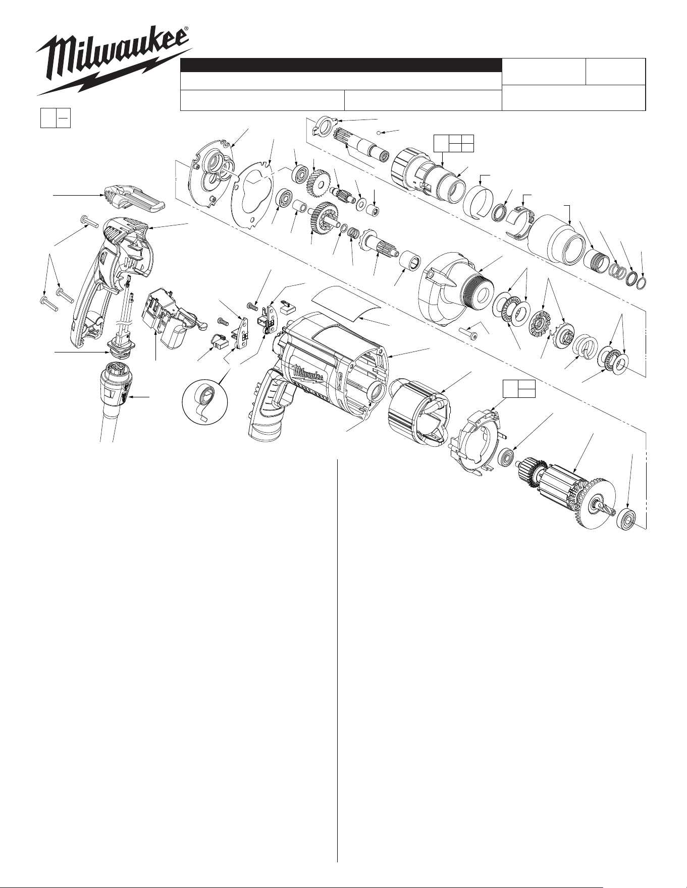
Cat. No. 31-53-0205
Lock Button Plug
4
16
3
19
34
14
22
9
33
23
21 10
29a
28
11
44a
44
48
25
51
32
55
2
13 45
52 54
64
53
1
46
52
13
54
45
50
38
56
43
49
2
36
40
60
5
35
58
41
39
6
57
31
11(3x)
7
37
47
42
8
59
70
FIG. PART NO. DESCRIPTION OF PART NO. REQ.
1 02-02-0130 Steel Ball (1)
2 02-04-0640 Ball Bearing (2)
3 02-04-0645 Ball Bearing (1)
4 02-04-0852 Ball Bearing (1)
5 02-50-2400 Needle Bearing (1)
6 02-50-3245 Needle Roller Bearing (1)
7 02-80-1200 Thrust Needle Bearing (1)
8 02-80-6020 Thrust Bearing (1)
9 05-88-1610 M3.5 x 10 Pan Hd. Plastite T-10 Scr (2)
10 23-52-1610 Brush Spring (2)
11 06-82-7275 7-18 x 3/4 Slotted Plastite Torx T-20 (6)
13 10-79-3100 Torque Setting Label (1)
14 12-99-2665 Service Nameplate (1)
16 16-10-2205 Armature (1)
19 18-07-7210 Field (1)
21 22-18-1310 Brush Assembly (2)
22 22-20-0090 Left Brush Holder (1)
23 22-20-0095 Right Brush Holder (1)
25 22-56-1000 Blade Housing Assembly (1)
28 48-76-5010 Quik-Lok Cord Set (1)
29a 23-66-2605 Defond Switch (See page 3 wiring) (1)
29b 23-66-2585 Marquardt Switch (See page 4 wiring) (1)
31 28-14-2405 Gearcase (1)
32 28-28-2315 Diaphragm (1)
33 31-15-2030 Handle Halve (1)
34 31-50-0524 Motor Housing (1)
35 32-10-4055 Clutch Gear Assembly (1)
36 32-40-0100 Intermediate Gear (1)
37 34-60-0545 Retaining Ring (1)
38 34-60-2390 Retaining Ring (1)
39 36-14-0665 Clutch Shaft Assembly (1)
40 36-66-0105 Intermediate Shaft (1)
41 40-50-6600 Separator Spring (1)
42 40-50-8000 Clutch Spring (1)
43 40-50-8005 Compression Spring (1)
44 42-14-0460 BafeAssembly (1)
44a 45-30-0030 Slug (Not Shown) (2)
45 42-16-0140 Adjustment Band (1)
46 42-66-0676 Chuck Shaft (1)
47 42-70-5016 Drive Clutch (2)
48 42-70-5280 Belt Clip (1)
49 42-76-0390 Locking Collar (1)
50 42-76-0460 Adjustment Collar (1)
51 43-44-0985 Gasket (1)
52 43-76-0550 Clutch Housing (1)
53 44-90-4280 Adjustment Ring (1)
00
0
EXAMPLE:
Component Parts (Small #)
Are Included When Ordering
The Assembly (Large #).
WIRING INSTRUCTION
REVISED BULLETIN DATE
SERVICE PARTS LIST
MILWAUKEE ELECTRIC TOOL CORPORATION
13135 W. LISBON RD., BROOKFIELD, WI 53005
Drwg. 1
BULLETIN NO.
STARTING
SERIAL NO.
54-42-6003
See Pages 3 & 4
SPECIFY CATALOG NO. AND SERIAL NO. WHEN ORDERING PARTS
6580-20
CATALOG NO.
ADJUSTABLE TORQUE SCREWDRIVER
Sept. 2013
098D
FIG. PART NO. DESCRIPTION OF PART NO. REQ.
54 45-06-0106 Oil Seal (1)
55 45-36-1280 Spacer (1)
56 45-36-1300 Spacer (1)
57 45-88-0510 Thrust Bearing Washer (2)
58 45-88-0712 Thrust Washer (1)
59 45-88-7150 Thrust Washer (2)
60 45-88-7990 Thrust Washer (1)
64 14-08-0190 Clutch Housing Assembly (1)
70 43-86-0125 Bearing Cup (1)
23-94-0490 White Leadwire Assy.
(See pages 3 & 4)
(1)
23-94-0495 Red Leadwire Assy.
(See pages 3 & 4)
(1)
LUBRICATION (Type "L" Grease, No. 49-08-4170)
• Place1.8gm.(.06oz.)ofgreaseonthedriveclutchsurfaces(47).
• Equallydistribute1.8gm.(.06oz.)ofgreaseonthethrustbearings
(7 and 8), oil seal (54) and the tabs of the adjustment ring (53).
LUBRICATION (Type "Y" Grease, No. 49-08-5270)
• Equallydistribute1.5gm.(.05oz.)ofgreaseonthelugsofthe
clutch gear (35), clutch shaft (39), separator spring (41) and the
thrust washer (58).
• Inthegearcase(31),place3.6gm.(.13oz.)ofgreaseinthe
counterbore above the inserted intermediate needle bearing (5).
• Place13gm.(.46oz.)ofgreaseatthearmaturepinionlocationin
thegearcase(31)andlltothetopoftheintermediategear(36).
Beforeassembly,lightlycoatallpresstareaswith
lightweightspindleoil.
FIG. NOTES:
5 Needle bearing to be pressed
ushto.010underushfrom
end which has the vendors
identication.
6 Needle bearing to have seal
toward the front of the tool.
=Partnumberchange from
previous service parts list.
54-42-6002
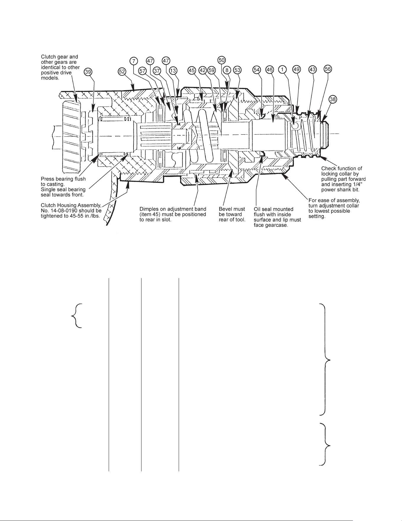
ORDER OF ITEM PART
ASSEMBLY NUMBER NUMBER DESCRIPTION
_____________________________________________________________________________________
1 64 14-08-0190 Clutch Hsg. Assy. (Includes Bushing No. 42-40-0920)
2 54 45-06-0106 Oil Seal
3 45 42-16-0140 Adjustment Band
4 13 10-79-3100 Torque Setting Label
5 53 44-90-4280 Adjustment Ring
6 46 42-66-0676 Chuck Shaft
7 1 02-02-0130 Steel Ball
8 49 42-76-0390 Locking Collar
9 43 40-50-8005 Spring
10 56 45-36-1300 Spacer
11 38 34-60-2390 Retaining Ring
12 59 45-88-7150 Thrust Washers (2 each)
(Place on each side of Item #8, Thrust Bearing)
13 8 02-80-6020 Thrust Bearing
14 42 40-50-8000 Clutch Spring
15 47 42-70-5016 Drive Clutch
16 37 34-60-0545 Retaining Ring
______________________________________________________________________________________
50 42-76-0460 Adjustment Collar (Includes insert No. 43-84-0740)
39 36-14-0665 Clutch Shaft Assembly
57 45-88-0510 Thrust Bearing Washers (2 each)
(Place on each side of Item #7, Thrust Bearing)
7 02-80-1200 Thrust Bearing
47 42-70-5016 Drive Clutch
Clutch
Sub-Assembly
NotInOrder
Of Assembly
ClutchHousing
Assembly
No. 14-08-0190
Sub-Assembly
Drive clutches must slide back and forth freely
on shaft splines. Defective splines that stick
will not function properly.
Lubrication
Apply1/16oz.Type"L"grease,No.49-08-4170,onclutchfacesofdriveclutch
(#47).Applyasmallamountof"L"greaseonthrustbearings(#7and#8),
oil seal lip (#54) and tabs of adjustment ring (#53).
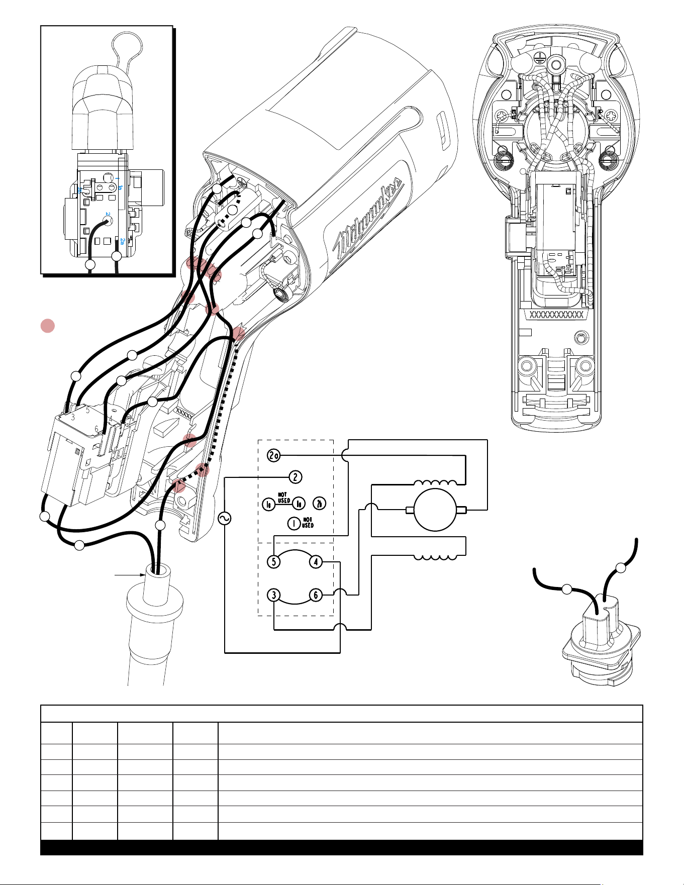
BULK LEAD WIRE - BULLETIN NO. 58-01-0003
Once the cord and
cord protector are
properly seated in
the motor housing,
the cord jacket is to
extend a minimium
of .25” beyond the
top of the cord
protector before
the handle halve
is assembled.
WIRING
SCHEMATIC
with DEFOND
SWITCH
DEFOND SWITCH
= WIRE TRAPS
or GUIDES
2
4
1
2
4
5
5
1
5
BOTTOM VIEW
OF SWITCH
AS AN AID TO REASSEMBLY,
TAKE NOTICE OF WIRE
ROUTING AND POSITION IN
WIRE GUIDES AND TRAPS
WHILE DISMANTLING TOOL.
BE CAREFUL AND AVOID
PINCHING WIRES BETWEEN
HANDLE HALVES WHEN
ASSEMBLING.
7
7
6
6
SWITCH
FWD
DIRECTION
BLACK
WHITE
BROWN
BLACK
WHITE
RED
LB RB
ARM
When used, orient blade
housing assembly with
white leadwire #2 on the
bottom and black leadwire
#1 on top when inserted into
bottom cavity of motor housing
2
1
1 Black * ----- *Component of cord set, pin hsg. assy. or blade hsg. assy. Connect to #2 on switch bottom.
2 White * ----- *Component of cord set, pin hsg. assy. or blade hsg. assy. Connect to #4 on switch top.
4 Brown Field ----- Componentofeld.Connectto#3onswitchtop.
5 Black Field ----- Componentofeld.Connectto#2aonswitchbottom.
6 White 23-94-0490 ----- Leadwire assembly. Connect to right brush holder and #5 on switch top.
7 Red 23-94-0495 ----- Leadwire assembly. Connect to left brush holder and #6 on switch top.
WIRING SPECIFICATIONS
Terminals, Connectors and 1 or 2 End Wire Preparation
Wire
Color
Origin or
Gauge
Wire
No.
Length
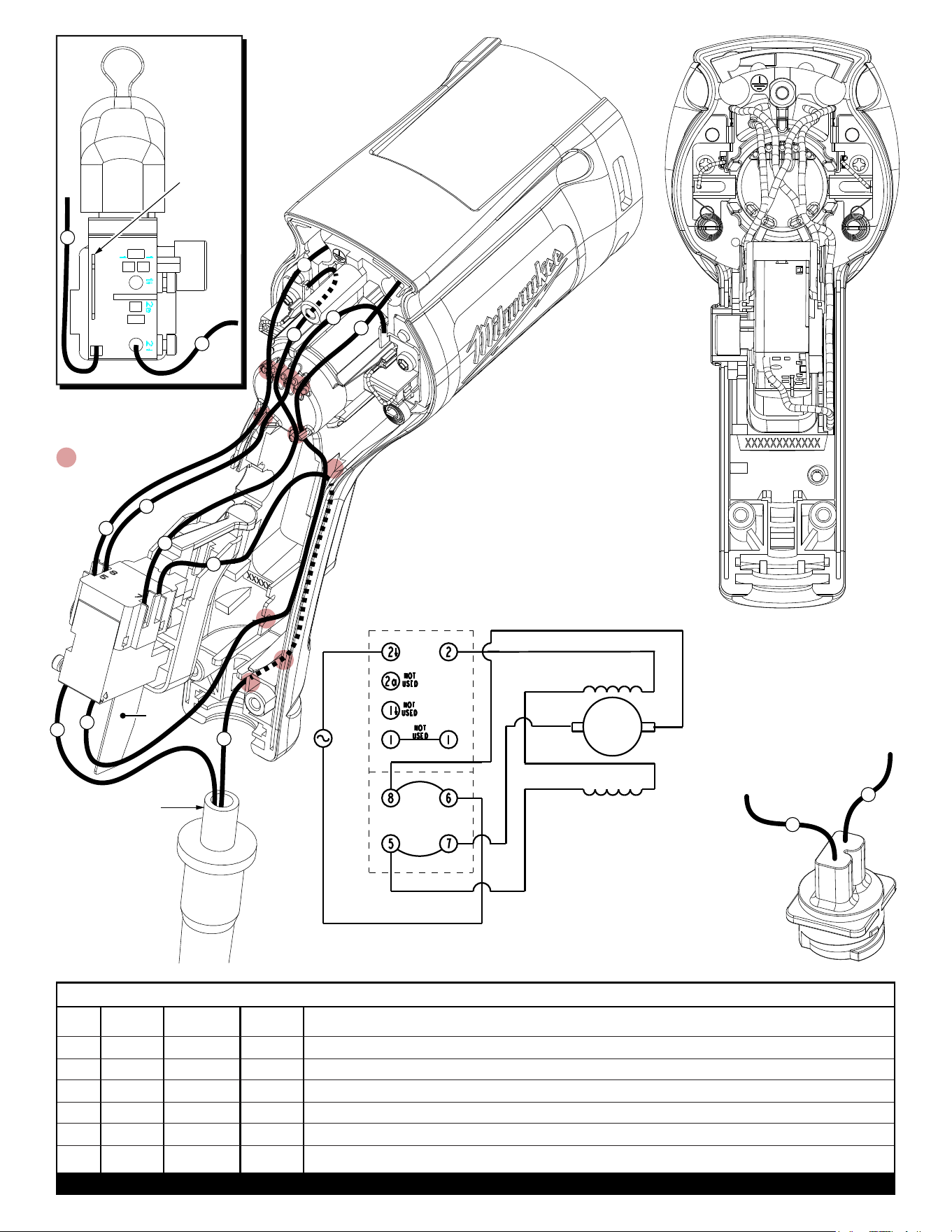
BULK LEAD WIRE - BULLETIN NO. 58-01-0003
1 Black * ----- *Component of cord set, pin hsg. assy. or blade hsg. assy. Connect to #2ò on switch bottom.
2 White * ----- *Component of cord set, pin hsg. assy. or blade hsg. assy. Connect to #6 on switch top.
4 Brown Field ----- Componentofeld.Connectto#5onswitchtop.
5 Black Field ----- Componentofeld.Connectto#2onswitchbottom.
6 White 23-94-0490 ----- Leadwire assembly. Connect to right brush holder and #8 on switch top.
7 Red 23-94-0495 ----- Leadwire assembly. Connect to left brush holder and #7 on switch top.
WIRING SPECIFICATIONS
Terminals, Connectors and 1 or 2 End Wire Preparation
Wire
Color
Origin or
Gauge
Wire
No.
Length
Once the cord and
cord protector are
properly seated in
the motor housing,
the cord jacket is to
extend a minimium
of .25” beyond the
top of the cord
protector before
the handle halve
is assembled.
WIRING
SCHEMATIC
with MARQUARDT
SWITCH
MARQUARDT SWITCH
= WIRE TRAPS
or GUIDES
2
4
7
1
2
4
7
BOTTOM VIEW
OF SWITCH
AS AN AID TO REASSEMBLY,
TAKE NOTICE OF WIRE
ROUTING AND POSITION IN
WIRE GUIDES AND TRAPS
WHILE DISMANTLING TOOL.
BE CAREFUL AND AVOID
PINCHING WIRES BETWEEN
HANDLE HALVES WHEN
ASSEMBLING.
5
Heat
Sink
Heat
Sink
5
1
5
6
6
BLACK
WHITE
SWITCH
BROWN
LB RB
RED
BLACK
FWD
DIRECTION
WHITE
When used, orient blade
housing assembly with
white leadwire #2 on the
bottom and black leadwire
#1 on top when inserted into
bottom cavity of motor housing
2
1