
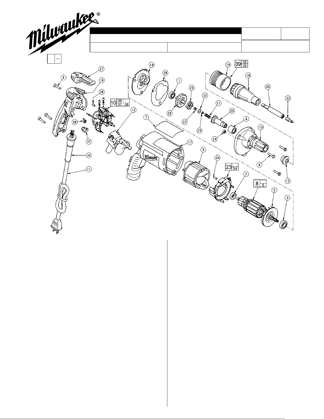
FIG. PART NO. DESCRIPTION OF PART NO. REQ.
1 02-04-0640 Ball Bearing (1)
2 02-04-0645 Ball Bearing (1)
3 02-04-0852 Ball Bearing (1)
4 02-50-3245 Needle Bearing (1)
5 22-84-0840 Fan (1)
6 06-82-7275 7-18 x 3/4" Slotted Plastite Torx T-20 (6)
7 12-99-2665 Service Nameplate (1)
8 16-10-2201 Armature (1)
9 18-07-2200 Field (1)
10 22-18-1210 Brush Card Assembly (1)
11 22-64-6510 Cord Assembly (1)
12 23-66-2585 Switch (1)
13 28-14-2375 Gearcase (1)
14 28-28-2315 Diaphragm (1)
15 30-37-0046 Drywall Nose Guide (1)
16 31-15-2010 Handle Halve (1)
17 31-50-2010 Motor Housing (1)
18 31-51-0095 Drywall Locator (1)
19 31-58-0515 Snap Sleeve (1)
20 32-10-0521 Clutch Gear Assembly (1)
21 40-50-0095 Separator Spring (1)
22 40-50-8515 Bias Spring (1)
23 42-14-0460 Baffle Assembly (1)
24 42-40-0045 Armature Bushing (1)
25 42-66-0715 Clutch Chuck Assembly (1)
26 42-70-0310 Drive Clutch (1)
27 42-70-5280 Belt Clip (1)
28 43-44-0985 Gasket (1)
29 44-60-0505 Thrust Pin (1)
30 44-76-0210 Cord Protector (1)
32 45-88-0555 Clutch Thrust Washer (1)
33 48-32-1040 #2 Phillips Insert Bit (1)
WIRING INSTRUCTION
REVISED BULLETIN DATE
SERVICE PARTS LIST
MILWAUKEE ELECTRIC TOOL CORPORATION
13135 W. LISBON RD., BROOKFIELD, WI 53005
Drwg. 1
BULLETIN NO.
STARTING
SERIAL NO.
54-42-6176
58-01-1800
SPECIFY CATALOG NO. AND SERIAL NO. WHEN ORDERING PARTS
6742-20
CATALOG NO.
DRYWALL SCREWDRIVER
June 2002
146B
FIG. PART NO. DESCRIPTION OF PART NO. REQ.
34 45-30-0030 Slug (2)
35 48-32-3065 Magnetic Bit Holder (1)
36 23-52-1610 Brush Spring (2)
37 22-18-1310 Brush Assembly (2)
38 45-30-0035 Slug (1)
39 49-26-1036 Drywall Locator Assembly (1)
FIG. LUBRICATION:
20,22 Place .02 oz. (.5 grams) of type "Y" grease, No 49-08-5270,
on bias spring. Place .02 oz. (.5 grams) total of grease in
the clutch pockets of clutch gear.
8,13 Place .27 oz. (7.6 grams) of type "Y" grease at the
armature pinion location in the gearcase pocket and push
down .20".
13,14 Apply a light film of type "Y" grease to needle and ball
bearing pockets in diaphragm and gearcase prior to
pressing bearings in.
21,32 Place .02 oz. (.5 grams) of type "Y" grease to clutch thrust
washer, thrust pin and separator spring during assembly.
EXAMPLE:
Component Parts (Small #) Are Included
When Ordering The Assembly (Large #).
00
0
FIG. NOTES:
4 Needle bearing to have it's seal toward the
front of the tool. Needle bearing to be
pressed .133/.143 under flush.
Cat. No.
31-53-0205
Lock Button
Plug
54-42-6175
«
«
«=Part number change
from previous service
parts list.