
50
19 30
20 38
51
9 17
18 39
52
23 32
26 37
53
22 25 27 28
29 33 35 36
54
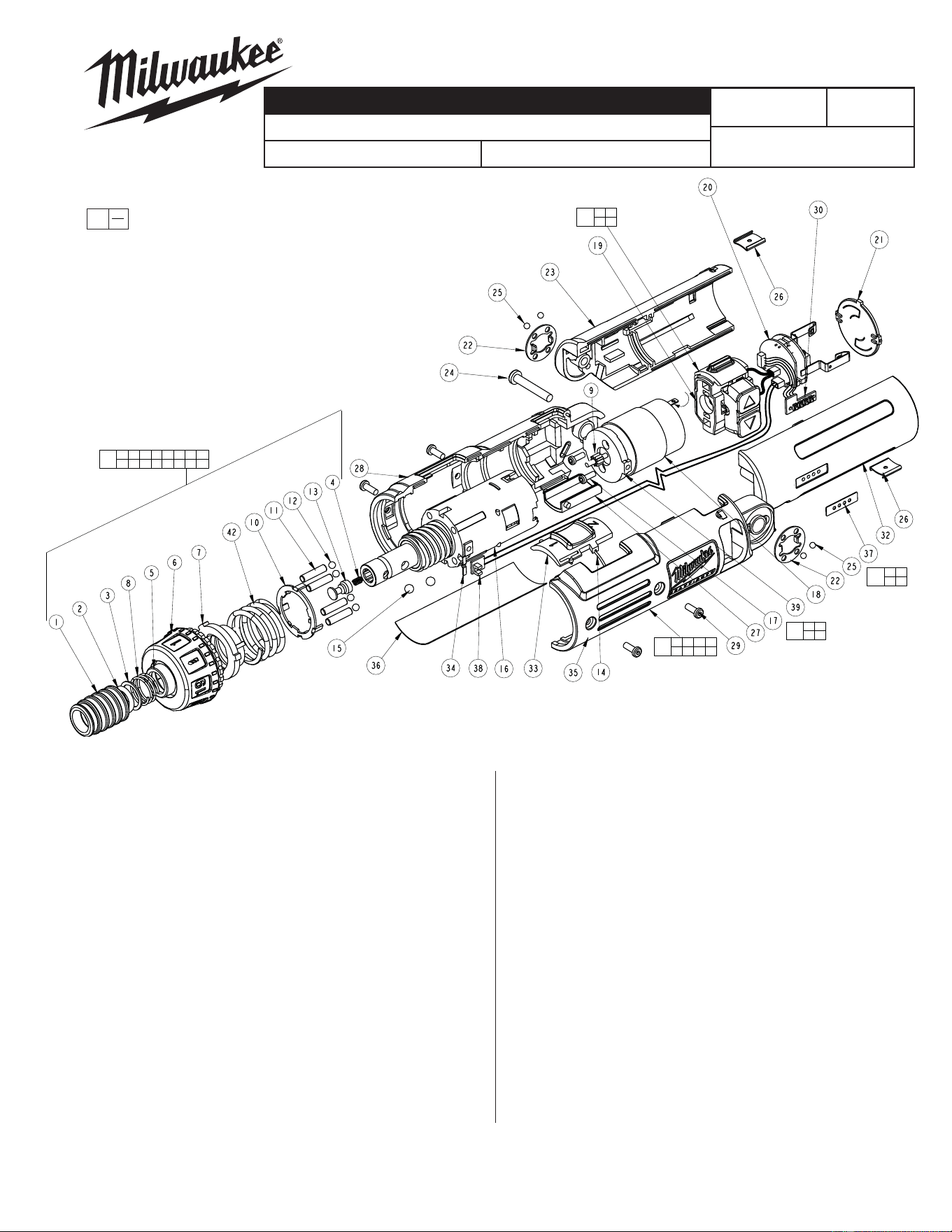
1 2 3 4 5 6 7 8
10 11 12 13 14 15 16 42
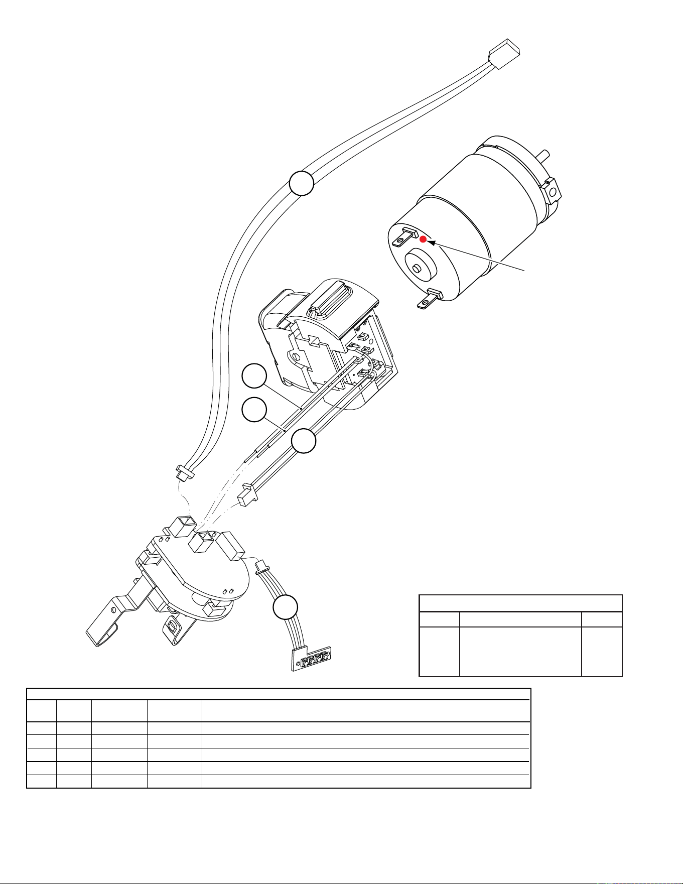
Positive terminal
(red dot) to the top
SPECIFY CATALOG NO. AND SERIAL NO. WHEN ORDERING PARTS
4 V Screwdriver
CATALOG NO. 0490-20
MILWAUKEE ELECTRIC TOOL CORPORATION
13135 W. Lisbon Road, Brookfi eld, WI 53005
Drwg. 3
54-42-0490
SERVICE PARTS LIST
BULLETIN NO.
00
0
EXAMPLE:
Component Parts (Small #)
Are Included When Order-
ing The Assembly (Large #).
B13A
REVISED BULLETIN
DATE
Mar. 2010
WIRING INSTRUCTION
SEE REVERSE
STARTING
SERIAL NUMBER
FIG. PART NO. DESCRIPTION OF PART NO. REQ.
1 ------------ Sleeve 1
2 ------------ Seal Ring 1
3 ------------ Bit Washer 1
4 ------------ Sleeve Spring 1
5 ------------ Press Ring 1
6 31-58-0085 Clutch Cap 1
7 45-22-0130 Sleeve 1
8 ------------ Spring Chuck 1
9 32-60-0255 Pinion Gear 1
10 44-90-0155 Washer Clutch 1
11 44-60-0185 Pin Clutch 4
12 02-02-0170 Ball 4
13 ------------ Shuttle 1
14 40-50-0485 Spring Shuttle 1
15 02-02-0175 Ball 2
16 ------------ Gearbox Assembly 1
17 05-82-0255 Screw 2
18 ------------ Motor 1
19 ------------ Switch Assembly 1
20 ------------ PCB Assembly 1
21 31-86-0125 Separator Plate 1
22 43-98-0105 Stamping 2
23 ------------ Handle Housing Cover 1
FIG. PART NO. DESCRIPTION OF PART NO. REQ.
24 05-83-0545 Screw 1
25 02-02-0165 Ball 4
26 40-50-0540 Spring Washer 2
27 31-15-0225 Hinge Plate 1
28 ------------ Handle Housing Support 1
29 05-78-0345 Screw 4
30 ------------ LED 1
32 ------------ Handle Housing Cover 1
33 44-10-0115 Knob (2 speed) 1
34 40-50-0545 Spring Plate 1
35 ------------ Handle Housing Support 1
36 12-20-0045 Service Nameplate 1
37 10-20-0655 LED Label 1
38 ------------ PCB Sensor Cable 1
39 44-66-0145 Motor Mount Plate 1
42 40-50-0480 Clutch Spring 1
50 23-66-1075 Switch Assembly Service Kit 1
51 14-50-0245 Motor Assembly Service Kit 1
52 31-44-0830 Handle Housing Service Kit 1
53 31-50-0080 Handle Housing Support Service Kit 1
54 14-29-0085 Gear Box Assembly Service Kit 1
TERMINAL DESCRIPTION
Code Part No. Qnty.
WIRING INSTRUCTIONS
WIRING SPECIFICATIONS
Wire Wire Origin or
No. Color Part No. Length Terminals, Connectors and End Wire Preparation
1 Multi 23-66-1075 -- PCB Sensor Cable - Component of the Switch Assembly Service Kit
2 Multi 23-66-1075 -- LED Assembly - Component of the Switch Assembly Service Kit
3 Multi 23-66-1075 -- Switch Wire Assembly - Component of the Switch Assembly Service Kit
4 Black 23-66-1075 -- Motor Wire to PCB - Component of the Switch Assembly Service Kit
5 Red 23-66-1075 -- Motor Wire to PCB - Component of the Switch Assembly Service Kit
3
2
1
4
5
Orient the
motor with the
positive terminal
(red dot) to the top