
FIG. PART NO. DESCRIPTION OF PART NO. REQ.
1 02-04-0640 Ball Bearing (2)
2 02-04-0645 Ball Bearing (1)
3 02-04-0852 Ball Bearing (1)
4 02-50-2400 Needle Bearing (1)
5 02-50-3245 Needle Bearing (1)
6 05-88-1610 M3.5 x 10 Pan Hd. Plastite T-10 (2)
9 06-82-7275 7-18 x 3/4" Slotted Plastite Torx T-20 (6)
10 23-52-1610 Brush Spring (2)
14 12-99-2665 Service Nameplate (1)
20 16-10-2205 Armature (1)
24 18-07-7210 Field (1)
26 22-18-1310 Brush Assembly (2)
27 22-20-0090 Left Brush Holder (1)
28 22-20-0095 Right Brush Holder (1)
34 22-64-6510 Cord Assembly (1)
35a 23-66-2605 Switch (Defond) See page 2 wiring (1)
35b 23-66-2585 Switch (Marquardt) See page 3 wiring (1)
38 28-14-2395 O.E.M. Gearcase (1)
40 28-28-2315 Diaphragm (1)
43 31-15-2010 Handle Halve (1)
45 31-50-0526 Motor Housing (1)
51 32-10-0525 Clutch Gear Assembly (1)
52 32-40-0100 Intermediate Gear (1)
53 36-66-0120 Intermediate Shaft (1)
54 40-50-0095 Separator Spring (1)
55 40-50-8515 Bias Spring (1)
56 42-14-0460 Baffl e Assembly (1)
56a 45-30-0030 Slug (Not Shown) (2)
57 42-66-0715 Clutch Chuck Assembly (1)
58 42-70-0310 Drive Clutch (1)
59 42-70-5280 Belt Clip (1)
60 43-44-0985 Gasket (1)
61 44-60-0505 Thrust Pin (1)
62 44-76-0210 Cord Protector (1)
63 45-36-1280 Spacer (1)
64 45-88-0555 Clutch Thrust Washer (1)
65 45-88-7990 Thrust Washer (1)
70 43-86-0125 Bearing Cup (1))
23-94-0490
White Leadwire Assy. (See pages 2 & 3)
(1)
23-94-0495
Red Leadwire Assy. (See pages 2 & 3)
(1)
31-53-0205 Lock Button Plug (Not Shown) (1)
WIRING INSTRUCTION
REVISED BULLETIN DATE
SERVICE PARTS LIST
MILWAUKEE ELECTRIC TOOL CORPORATION
13135 W. LISBON RD., BROOKFIELD, WI 53005
Drwg. 1
BULLETIN NO.
STARTING
SERIAL NO.
54-42-6303
See Pages 2 & 3
SPECIFY CATALOG NO. AND SERIAL NO. WHEN ORDERING PARTS
6792-20
CATALOG NO.
O.E.M. POWER UNIT
Sept. 2013
181D
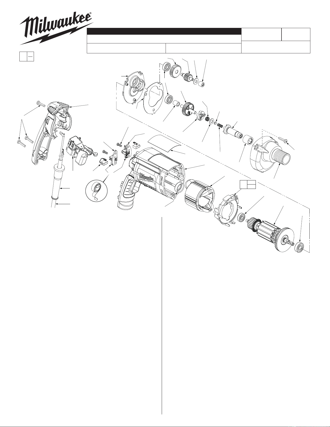
LUBRICATION (Type "Y" Grease, No. 49-08-5270)
• Fill the 3 enlarged clutch pockets of the clutch gear assembly (51)
with .5 gm. (.02 oz.) grease.
• Apply the same amount of grease in the bias spring (55).
• Apply in total .5 gm. (.02 oz.) grease to the clutch thrust washer
(64), thrust pin (61) and separator spring (54).
• Place 7.7 gm. (.27 oz.) of grease at the armature pin location in the
gearcase (38) and fi ll to slightly above the next higher gearcase
level.
• Apply a light fi lm of grease to the lead chamfer of the clutch
chuck (57) prior to assembly.
Before assembly, lightly coat all press fi t areas with
lightweight spindle oil.
FIG. NOTES:
5 Needle bearing to have it's seal toward the front of the tool.
Needle bearing to be pressed .133/.143 under fl ush.
EXAMPLE:
Component Parts (Small #) Are Included
When Ordering The Assembly (Large #).
00
0
54-42-6302
= Part number change from
previous service parts list.
3
20
2
24
45
14
27
6
43
28
26 10
35a
62
34
9
56a
56
51
58
55
64
61
54
57
5
38
60
40
1
9(3x)
52 53 65 4
63
70
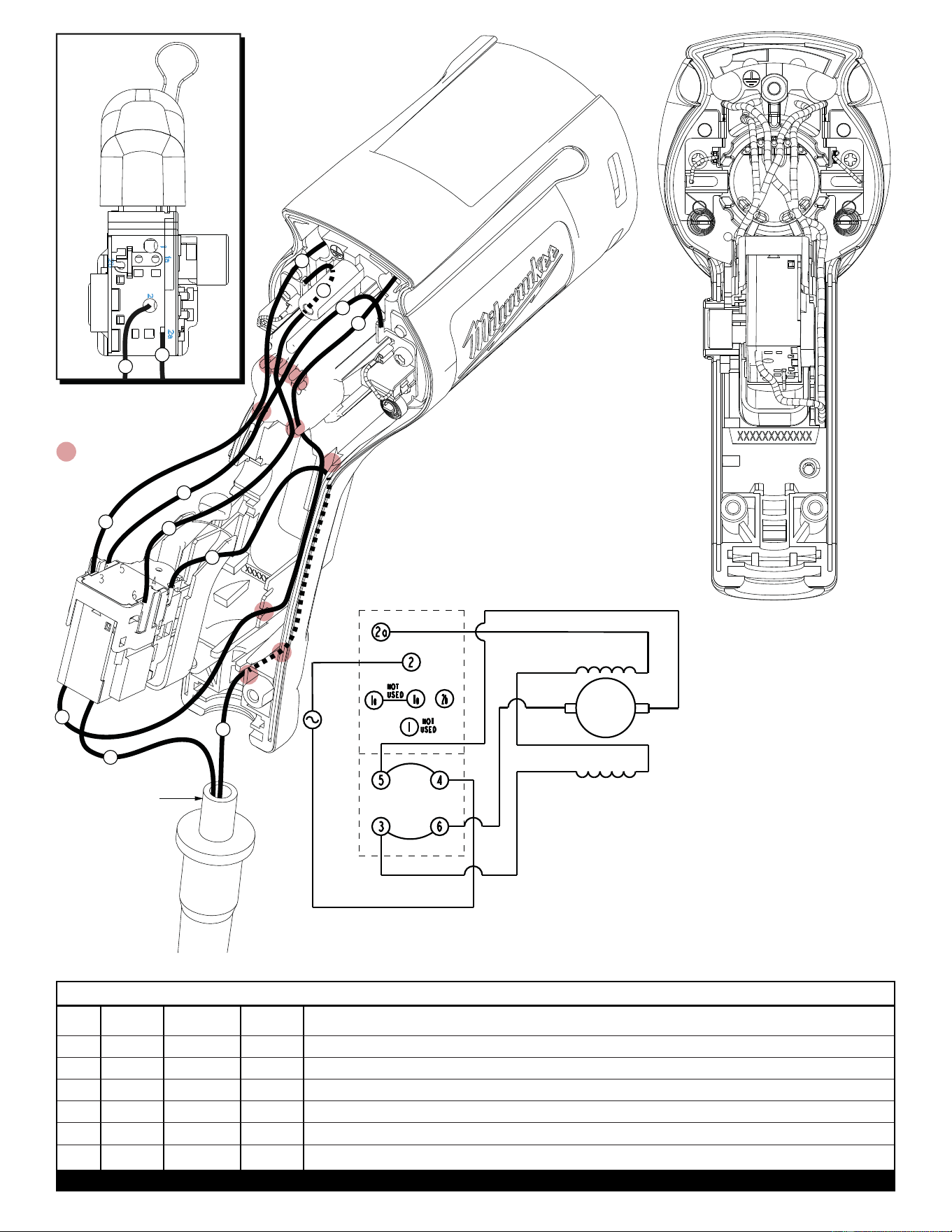
BULK LEAD WIRE - BULLETIN NO. 58-01-0003
Once the cord and
cord protector are
properly seated in
the motor housing,
the cord jacket is to
extend a minimium
of .25” beyond the
top of the cord
protector before
the handle halve
is assembled.
WIRING
SCHEMATIC
with DEFOND
SWITCH
DEFOND SWITCH
= WIRE TRAPS
or GUIDES
2
4
1
2
4
5
5
1
5
BOTTOM VIEW
OF SWITCH
AS AN AID TO REASSEMBLY,
TAKE NOTICE OF WIRE
ROUTING AND POSITION IN
WIRE GUIDES AND TRAPS
WHILE DISMANTLING TOOL.
BE CAREFUL AND AVOID
PINCHING WIRES BETWEEN
HANDLE HALVES WHEN
ASSEMBLING.
7
7
6
6
SWITCH
FWD
DIRECTION
BLACK
WHITE
BROWN
BLACK
WHITE
RED
LB RB
ARM
1 Black * ----- *Component of cord set, pin hsg. assy. or blade hsg. assy. Connect to #2 on switch bottom.
2 White * ----- *Component of cord set, pin hsg. assy. or blade hsg. assy. Connect to #4 on switch top.
4 Brown Field ----- Component of fi eld. Connect to #3 on switch top.
5 Black Field ----- Component of fi eld. Connect to #2a on switch bottom.
6 White 23-94-0490 ----- Leadwire assembly. Connect to right brush holder and #5 on switch top.
7 Red 23-94-0495 ----- Leadwire assembly. Connect to left brush holder and #6 on switch top.
WIRING SPECIFICATIONS
Terminals, Connectors and 1 or 2 End Wire Preparation
Wire
Color
Origin or
Gauge
Wire
No.
Length
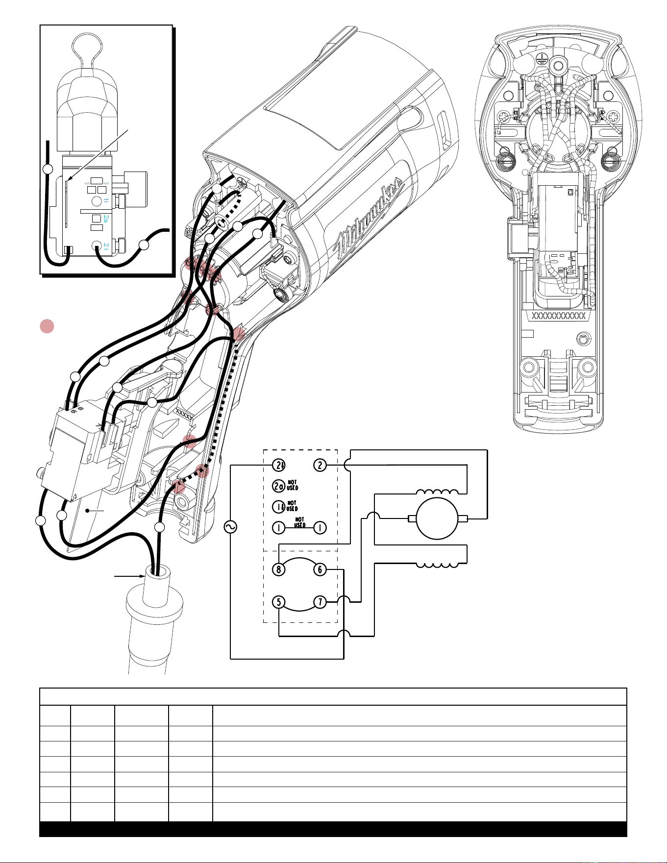
BULK LEAD WIRE - BULLETIN NO. 58-01-0003
1 Black * ----- *Component of cord set, pin hsg. assy. or blade hsg. assy. Connect to #2 on switch bottom.
2 White * ----- *Component of cord set, pin hsg. assy. or blade hsg. assy. Connect to #6 on switch top.
4 Brown Field ----- Component of fi eld. Connect to #5 on switch top.
5 Black Field ----- Component of fi eld. Connect to #2 on switch bottom.
6 White 23-94-0490 ----- Leadwire assembly. Connect to right brush holder and #8 on switch top.
7 Red 23-94-0495 ----- Leadwire assembly. Connect to left brush holder and #7 on switch top.
WIRING SPECIFICATIONS
Terminals, Connectors and 1 or 2 End Wire Preparation
Wire
Color
Origin or
Gauge
Wire
No.
Length
Once the cord and
cord protector are
properly seated in
the motor housing,
the cord jacket is to
extend a minimium
of .25” beyond the
top of the cord
protector before
the handle halve
is assembled.
WIRING
SCHEMATIC
with MARQUARDT
SWITCH
MARQUARDT SWITCH
= WIRE TRAPS
or GUIDES
2
4
7
1
2
4
7
BOTTOM VIEW
OF SWITCH
AS AN AID TO REASSEMBLY,
TAKE NOTICE OF WIRE
ROUTING AND POSITION IN
WIRE GUIDES AND TRAPS
WHILE DISMANTLING TOOL.
BE CAREFUL AND AVOID
PINCHING WIRES BETWEEN
HANDLE HALVES WHEN
ASSEMBLING.
5
Heat
Sink
Heat
Sink
5
1
5
6
6
BLACK
WHITE
SWITCH
BROWN
WHITE
LB RB
RED
BLACK
FWD
DIRECTION
WHITE