®
Installer Manual
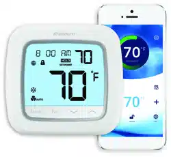
Smart Wi-Fi Thermostats
Possible electric shock or damage to equipment can occur.
Disconnect power before beginning installation.
Caution
ST920WF
Up to 3 Heat / 2 Cool Heat Pump
Up to 2 Heat / 2 Cool Conventional
ST921WF
Up to 2 Heat / 1 Cool Heat Pump
2 Heat / 1 Cool Conventional
1 Heat / 2 Cool Conventional
Warning
For installation by experienced service technicians only.
1
SPECIFICATIONS
ST920WF-100-01
This thermostat requires 24 Volt AC Power.
For use only as described in this manual. Any other use will void warranty.
This manual is for Installer use only.
TM
1
Specifications
2
Installation
3
Quick Reference
4
Mobile Setup
5
Manual Setup
6
System Testing
Model number is located on back of thermostat.
This thermostat is compatible with:
• Single stage conventional and heat pump systems
• Single stage heat pumps with auxiliary heat
• Heat pump systems with 2 compressors and auxiliary heat (ST920WF)
• Conventional systems up to 2 stages of heat and 2 stages of cool (ST920WF)
• Heating only systems
• Cooling only systems
Electrical and Control Specifications
• Electrical Rating: 24 Volt AC
• 1 amp maximum load per terminal
• AC Power: 18 – 30 Volts AC
• Control Range: 50° to 90° F (10° to 32° C)
• Temperature Accuracy: +/- 1.5° F (+/- 1.0° C)
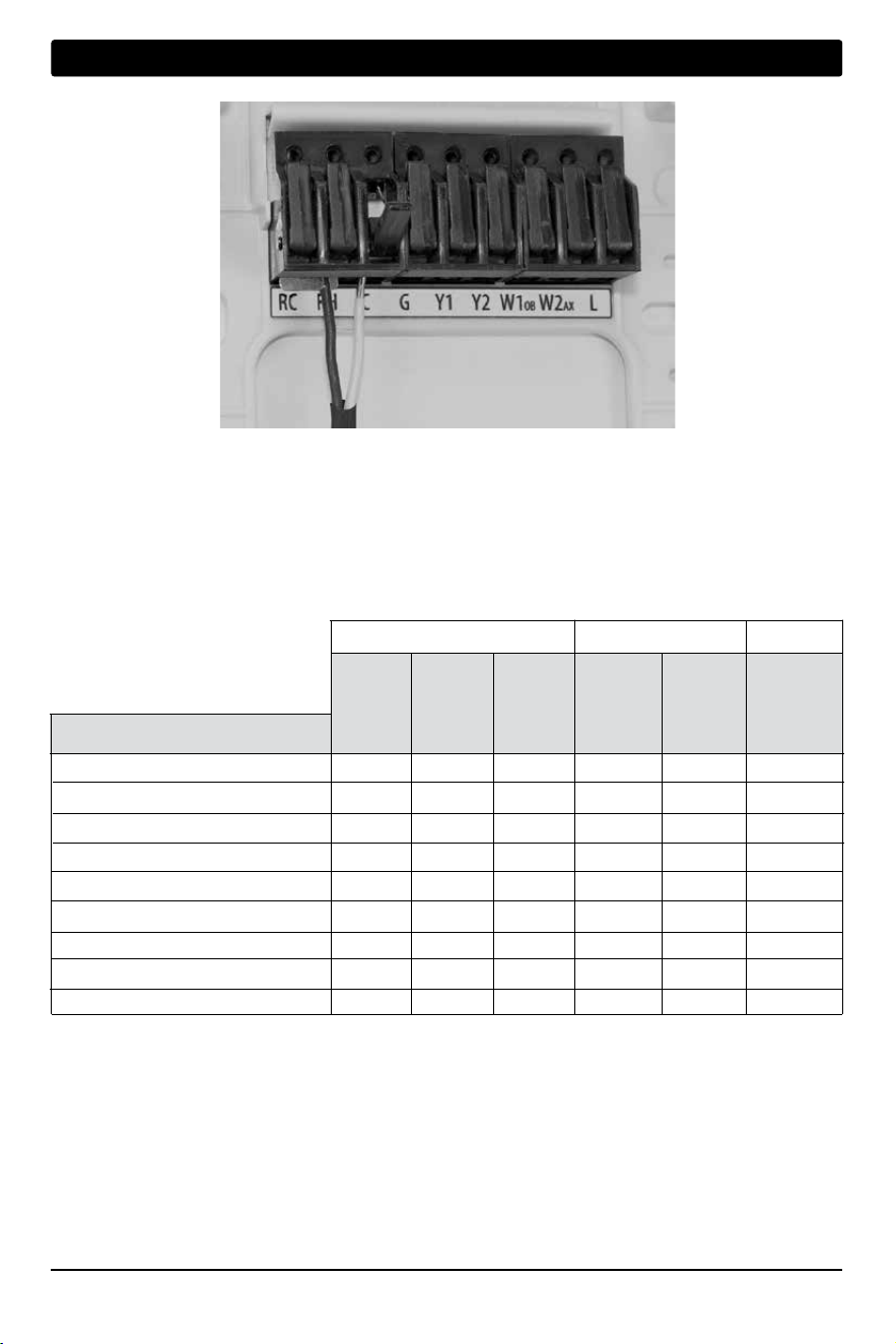
Terminations
ST920WF: Rc, Rh, W1/OB, W2/AX, Y1, Y2, G, L, C
ST921WF: Rc, Rh, W1/OB, Y1,
*
, G, L, C
Installer Manual 2
2
INSTALLATION
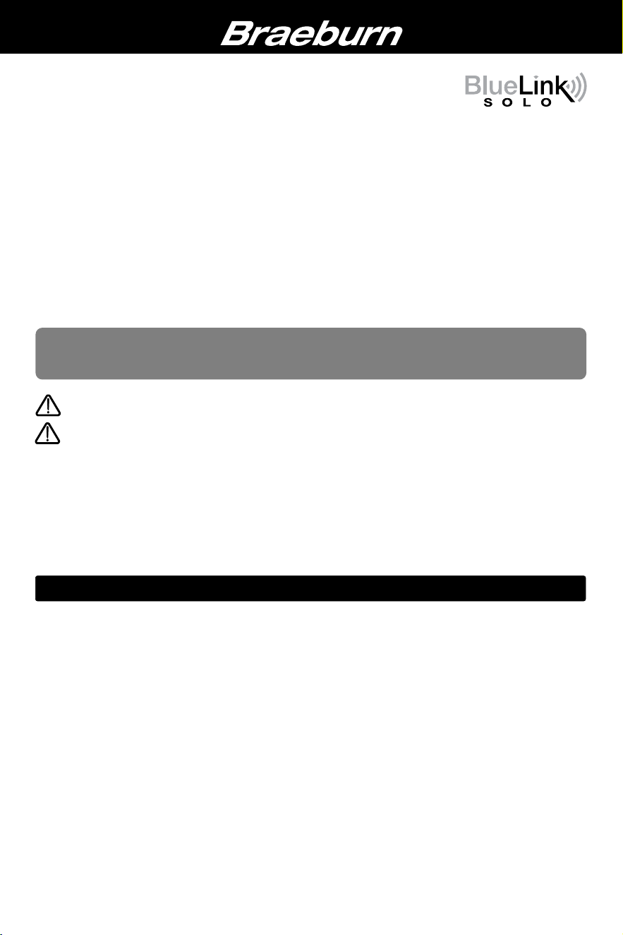
Thermostat Location
Install the thermostat approximately 5 feet (1.5m) above the floor in an area that has a good amount of air
circulation and maintains an average room temperature.
Avoid installation in locations where the thermostat can be affected by drafts, dead air spots, hot or cold air
ducts, sunlight, appliances, concealed pipes, chimneys and outside walls.
Warning
Disconnect power before beginning installation.
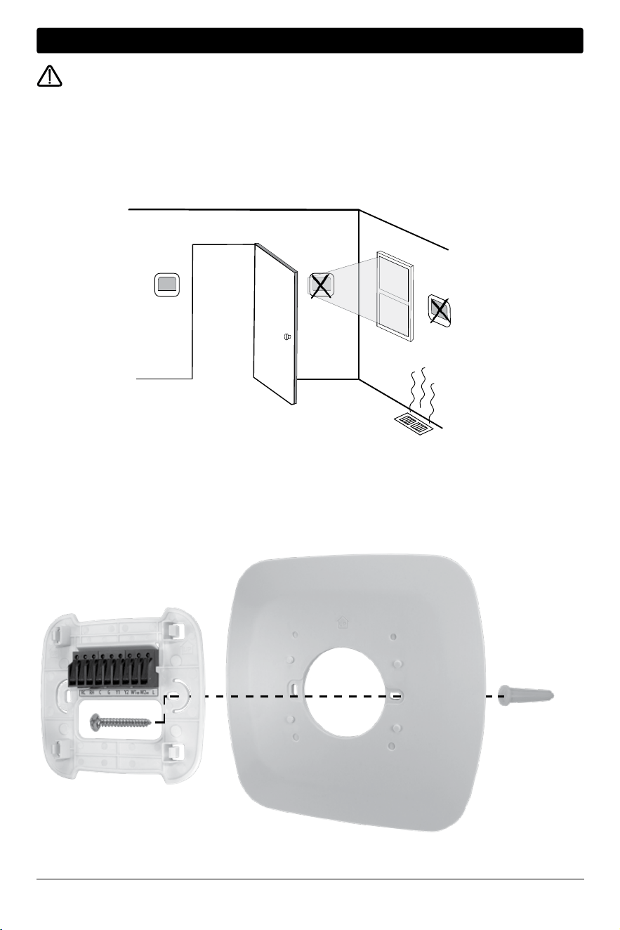
Install the Sub-Base:
• Remove the sub-base from the body of the thermostat.
• Mount the sub-base as shown below:
Drill 3/16” pilot holes in your desired location.
Use supplied anchors for drywall or plaster.
3 Installer Manual
Attach Wiring - To insert a wire into a terminal, flip up the locking tab and slide the wire into the terminal
directly above the corresponding label. Insert each wire as required for the desired application. Once each wire is
inserted, flip the tab down to lock it in position. Then pull gently on each wire to be sure the wire is secure.
2
INSTALLATION
Conventional Systems - Typical Wiring Configurations for HVAC: CONV
ST920WF or ST921WF ST921WF ST920WF
1 Heat 0 Heat 1 Heat 2 Heat 1 Heat 2 Heat
0 Cool 1 Cool 1 Cool 1 Cool 2 Cool 2 Cool
24 VAC Cooling Transformer Rc Rc Rc
1
Rc
1
Rc
1
Rc
1
24 VAC Heating Transformer - - Rh
1, 2
Rh
1, 2
Rh
1, 2
Rh
1, 2
24 VAC Transformer Common C
C
C
3
C
3
C
3
C
3
Fan Relay G
4
G G G G G
1st Stage Cooling - Y
1 - - Y1
Y1
2nd Stage Cooling - - - -
*
5
Y2
1st Stage Conventional Heat W
1 - W1 W1 W1 W1
2nd Stage Conventional Heat - - -
*
5
- W2
Unused - - - - -
-
“HVAC” and “System Type” are configured in the Settings - See section 5
NOTES - Conventional Systems
1 Remove factory installed jumper for dual transformer systems
2 Only required for dual transformer systems
3 For dual transformer systems, common must come from cooling transformer
4 Only connect if needed for system
5 The * (Asterisk) terminal functions as either Y2 or W2 depending on configuration
Provide disconnect and overload protection as required.
Terminal Description
Heating Stages
Cooling Stages
System Type: System Type: System Type: System Type: System Type: System Type:
HEAT COOL HEAT/COOL HEAT/COOL HEAT/COOL HEAT/COOL
MODEL
Installer Manual 4
2
INSTALLATION
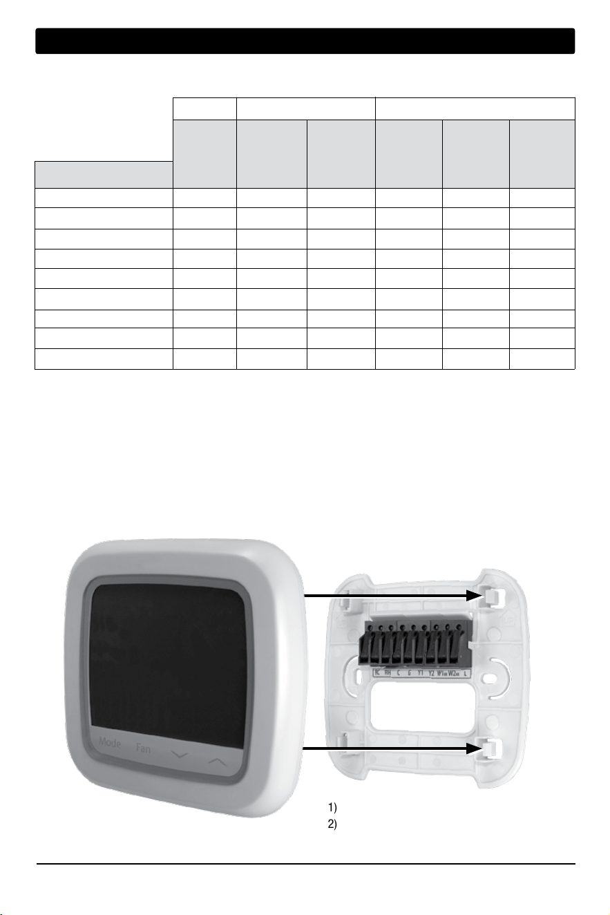
Attach to Thermostat Sub-Base
1) Line up the thermostat body with the sub-base.
2) Carefully push the thermostat body against the
sub-base until it snaps in place.
Once you complete the wiring in Section 2,
attach thermostat to sub-base and then
configure the Settings in Section 5.
Heat Pump Systems - Typical Wiring Configurations for HVAC: HT PUMP or D FUEL
Both ST921WF ST920WF
1 Heat Pump 1 Heat Pump 1 Heat Pump 1 Heat Pump 2 Heat Pump 2 Heat Pump
0 Auxiliary 0 Auxiliary 1 Auxiliary 1 Auxiliary 0 Auxiliary 1 Auxiliary
24 VAC Cooling Transformer Rc Rc Rc Rc
Rc
Rc
24 VAC Heating Transformer - - - - - -
24 VAC Transformer Common C
C
C
C
C
C
Fan Relay G G G G G G
1st Compressor Stage Y
1
Y1 Y1 Y1 Y1
Y1
2nd Compressor Stage - - - - Y2 Y2
Reversing Valve OB
1
OB
1
OB
1
OB
1
OB
1
OB
1
Auxiliary Heating Stage - -
*
2
- AX AX
System Malfunction Indicator L L L L L L
“HVAC” and “System Type” are configured in the Settings - See section 5
NOTES - Heat Pump Systems
1 O (cool active) or B (heat active) is selected in the Installer Settings menu
2 The * (Asterisk) terminal functions as either Y2 or W2 depending on configuration
Provide disconnect and overload protection as required.
Terminal Description
Heat Pump Stages
Auxiliary Heating Stages
System Type: System Type: System Type: System Type: System Type: System Type:
HEAT/COOL HEAT/COOL HEAT/COOL HEAT/COOL HEAT/COOL HEAT/COOL
MODEL
5 Installer Manual
3
QUICK REFERENCE
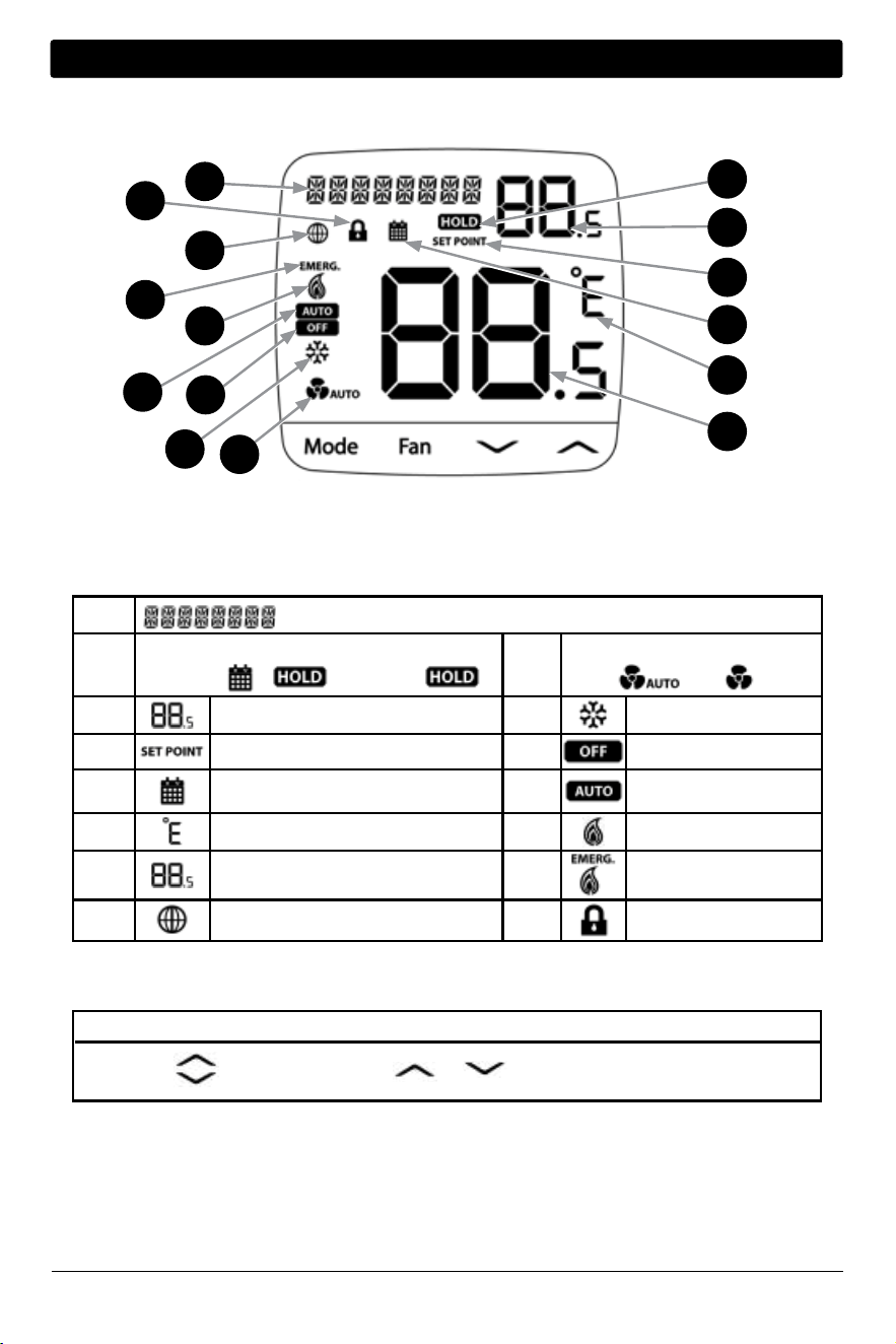
1
Alphanumeric text display
2
Schedule Override Indicator
Temporary:
&
Permanent:
9
Fan indicator:
Auto -
On -
3
Setpoint or parameter value
10
Cooling Mode
4
Setpoint indicator
11
Off Mode
5
Schedule running indicator
12
Auto Cooling/
Heating mode
6
Fahrenheit or Celsius units
13
Heating Mode
7
Room Temperature
14
Emergency Heat mode
8
Wi-Fi indicator
15
Key lock indicator
7
6
5
4
3
2
1
9
15
8
14
13
12
11
10
Display Characters
Mode -
Mode Selection
Fan -
Fan Speed Selection
Increase Value
Decrease Value
Mode + Fan -
Toggle ˚F or ˚C
+
Hold for 3 seconds to
lock/unlock thermostat
Buttons
1 Heat Pump 1 Heat Pump 1 Heat Pump 1 Heat Pump 2 Heat Pump 2 Heat Pump
0 Auxiliary 0 Auxiliary 1 Auxiliary 1 Auxiliary 0 Auxiliary 1 Auxiliary
24 VAC Cooling Transformer Rc Rc Rc Rc
Rc
Rc
24 VAC Heating Transformer - - - - - -
24 VAC Transformer Common C
C
C
C
C
C
Fan Relay G G G G G G
1st Compressor Stage Y
1
Y1 Y1 Y1 Y1
Y1
2nd Compressor Stage - - - - Y2 Y2
Reversing Valve OB
1
OB
1
OB
1
OB
1
OB
1
OB
1
Auxiliary Heating Stage - -
*
2
- AX AX
System Malfunction Indicator L L L L L L
4
Installer Manual 6
5
MANUAL SETUP
Description Available
Settings
Description of Available Settings
MOBILE SETUP - Use for Mobile Setup
This is the default option. To use mobile setup, simply keep choose this option and open the
BlueLink SOLO application to connect and configure your thermostat.
MANUAL SETUP NO Returns to MOBILE SETUP
YES Starts MANUAL SETUP
RESET Factory Resets the device
Select YES for this option if you wish to configure the thermostat manually. If you wish to
return to MOBILE setup, you can select NO. Selecting RESET will factory reset the device.
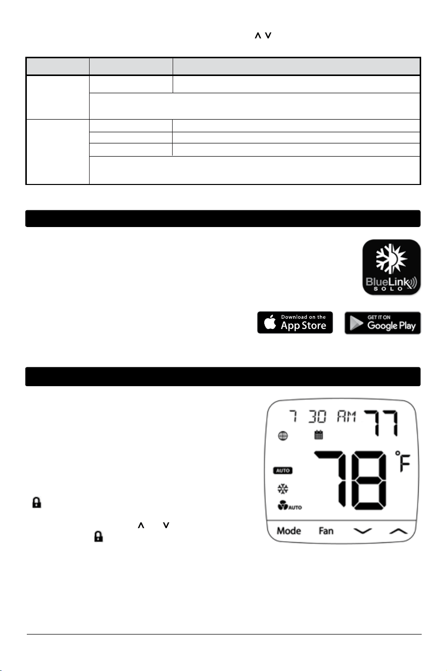
The thermostat must be properly configured to operate correctly. Upon powerup or after a factory reset, you are
presented with the option for MOBILE or MANUAL SETUP. Use the button to move from MOBILE to MANUAL
SETUP, if desired.
When MOBILE SETUP begins scrolling across the screen, the thermostat is ready to
connect
with the application.
Download the BLUELINK SOLO application on your iOS or Android device. After downloading
the application, follow the steps in the BLUELINK SOLO Mobile Application to complete setup
and installation.
If is displayed, you must unlock the thermostat to proceed.
To unlock the thermostat, press and at the same time for
3 seconds until the icon disappears.
If an internet connection is not available or you prefer to configure
the thermostat manually, you can choose MANUAL SETUP to do so.
This will bring you into a device configuration menu.
See pages 7-10 for instructions on how to navigate this menu.
This menu can also be accessed at any time after the initial
configuration by pressing MODE and FAN at the same time
for 5 seconds.
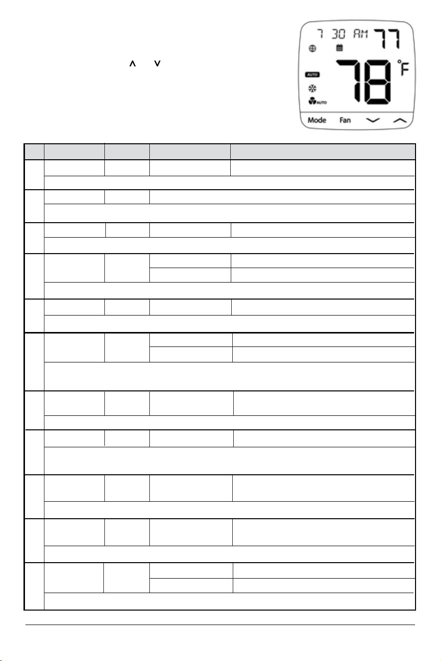
4
MOBILE SETUP
7 Installer Manual
No.
Description
Default
Available Settings
Description of Available Settings
1 SYSTEM - - -
Select this option to enter the SYSTEM submenu. (See page 8).
2 TIME ZONE - Pacific Eastern, Central, Mountain, Pacific, Alaska, Hawaii
3 TIME DATE - - -
Select this option to enter the TIME DATE submenu. (See page 9).
4 FORMAT 12
Select the format for the clock, either 12 hours with AM/PM or 24 hours.
5
NETWORK - - -
6 FROST NO
12 Select for a 12 hour clock
24 Select for a 24 hour clock
Select this option to enter the Wi-Fi NETWORK submenu. (See page 10).
NO Select to disable Frost Protection
YES Select to enable Frost Protection
Frost Protection will run the heat regardless of system state whenever the room temperature falls below the
frost setpoint. The default frost setpoint is 41˚F (5˚C), and this can be adjusted from the application.
7 TEMP CAL 0 -6 to 6˚
Select an offset to the display temperature of -6 to 6˚F
(-3 to 3˚C)
Select a temperature calibration or offset to apply to the reading.
8 SPAN 0.5 0.5, 1.0, 2.0 Select a 1st stage Span to control cycling.
Select the range of temperature to control the degree of separation between the setpoint temperature and the
first stage of heating or cooling.
9
D2 2 1 to 20 Select a second stage differential of 1-20°F.
(0.5 - 10°C)
Selects a differential which controls the degree of separation between the 1st and 2nd stage of heating or cooling.
10 DEADBAND 2 2, 3, 4 Select a deadband for autochangeover of 2, 3, or
4°F (1, 1.5, or 2°C).
When using auto changeover mode, the dead band determines the separation between heating and cooling.
NO
NO Selecting NO will not reset the thermostat.
YES Select to factory reset the thermostat.
11 FACTORY
Selecting YES will return the thermostat to all factory default settings.
Select the time zone for your thermostat.
To Access the Menu after Initial Setup:
1) Press MODE and FAN at the same time for 5 seconds.
2) While in the menu, use the and arrows to
change the selected option.
3) Use FAN to confirm the option, and MODE to back
out of current option or submenu.
Manual Setup Menu
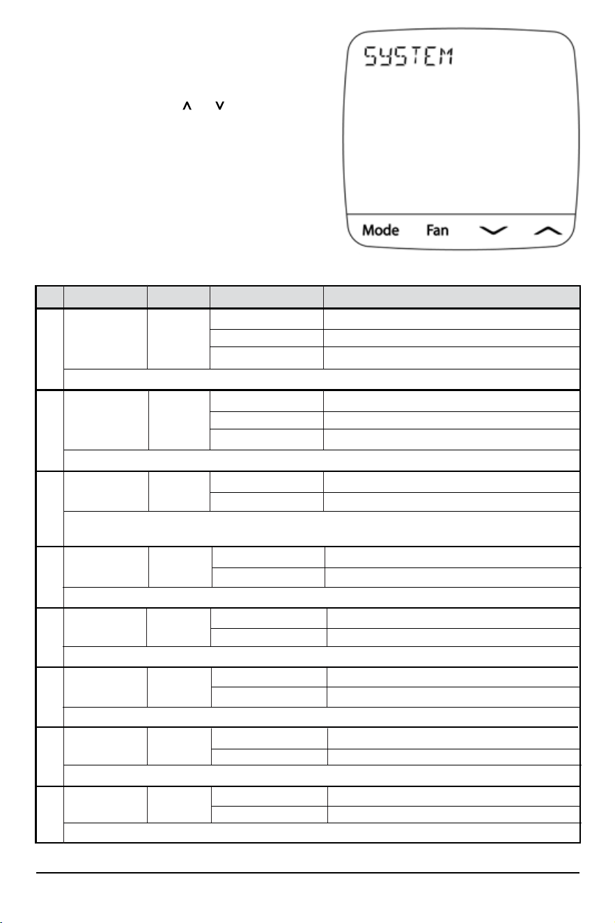
Installer Manual 8
No.
Description
Default
Available Settings
Description of Available Settings
To Access this Submenu:
1) Press FAN when viewing the option #1 SYSTEM
in the main menu (see page 7).
2) While in the menu, use the and arrows
to change the selected option.
3) Use FAN to confirm the option, and MODE to back
out of current option or submenu.
NOTE: This menu is adaptive and available options
will vary based on your previous selections.
1a
HVAC CONV
CONV Select for Conventional Systems
HT PUMP Select for Heat Pump Systems
D FUEL Select for Heat Pumps with fossil fuel auxiliary
Select the type of heating and cooling equipment controlled.
1b SYS TYPE HEAT
HEAT Select for Heat Only Systems
COOL Select for Cool Only Systems
HEATCOOL Select for Heating and Cooling Systems
Select the heating and/or cooling function of your equipment.
1c FAN TYPE GAS
GAS Select for Gas heating systems
ELECTRIC Select for Electric heating systems
This option controls whether or not the fan is called alongside the heat. To activate the fan alongside the heating,
select ELECTRIC. If GAS is selected, the fan will not be called alongside the heat.
1d
HP TYPE o
Select the switching operation for the changeover or reversing valve.
o Select for O (Cool Active) reversing valve
b Select for B (Heat Active) reversing valve
1e COOL STA 1
1 Select for one stage of cooling
2 Select for two stages of cooling
1f HEAT STA 1
1 Select for one stage of heating
2 Select for two stages of heating
1g HP STA 1
Select the number of heat pump stages for heating and cooling.
1 Select for one stage of heat pump
2 Select for two stages of heat pump
1h AUX HEAT 1
Select the number of heat pump stages for heating and cooling.
0 Select for no auxiliary heat
1 Select for one stage of auxiliary heat
System Submenu
Select the number of cooling stages.
Select the number of heating stages.
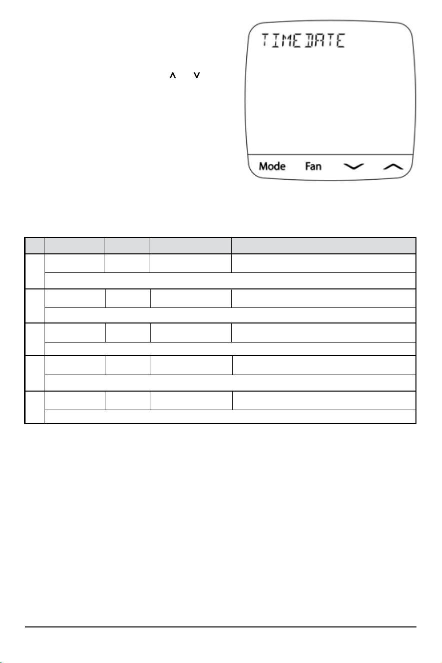
9 Installer Manual
To Access this Submenu:
1) Press FAN when viewing the option #3 TIME DATE in the
main menu (see page 7).
2) Change settings as required using the and arrows.
3) Use FAN to confirm a selection, or use MODE to back
out of the current option or sub-menu.
NOTE: This menu is not available while the thermostat is connected to the cloud, as the clock will update
automatically based on your time zone.
No.
Description
Default
Available Settings
Description of Available Settings
3a YEAR 20
20 - 99 Select the current year
Select the current year by selecting the last two digits. The first two digits are always assumed to be 20--.
3b MONTH 01
01 - 12 Select the current month
Select the current month from January to December by selecting the number of the month from 01 to 12.
3c DAY 01
01 - 31 Select the current day
Select the current day from the 1st to the 31st.
3d HOUR 12AM
12AM TO 11PM Select the current hour
Select the current hour from 12AM to 11PM.
3e MINUTE 00
00 to 59 Select the current minutes
Select the current minutes from --:00 to --:59
Time/Date Submenu
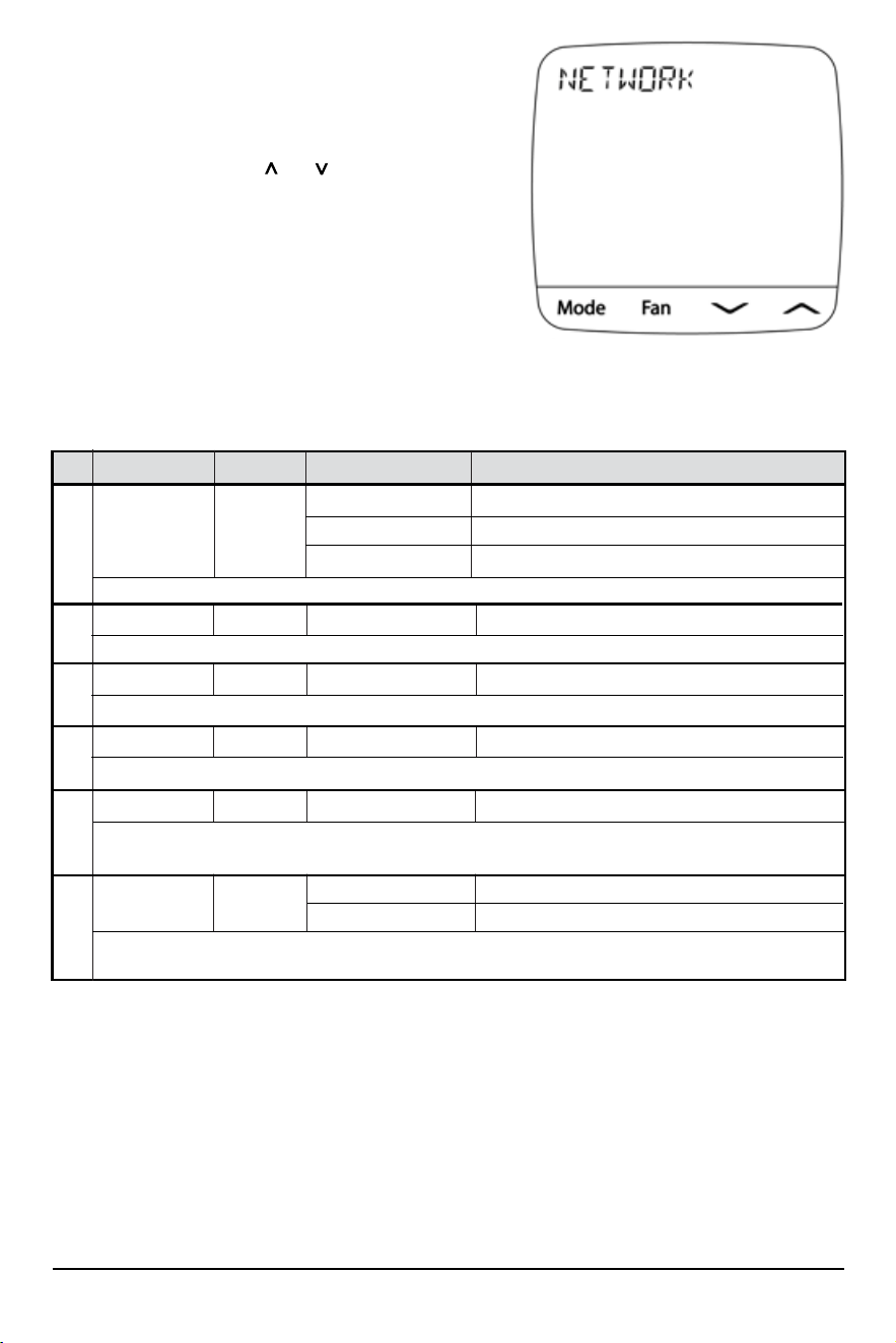
Installer Manual 10
To access this submenu:
1) Press FAN when viewing the option #5 NETWORK in
the main menu (see page 7).
2) While in the menu, use the and arrows to
change the selected option.
3) Use FAN to confirm the option, and MODE to back out of
current option or submenu.
NOTE: Many of the options in this menu are read-only, and can only be viewed when the thermostat has a
Wi-Fi connection.
No.
Description
Default
Available Settings
Description of Available Settings
5a STATUS 0
0 No Connection
1 Connected
2 Lost Connection
Press FAN to display the current status of the Wi-Fi network and cloud connection.
5b SSID -
Press FAN to display the SSID (network name) of the Wi-Fi network saved to the thermostat.
- Shows the current SSID
5c IP ADDR -
Press FAN to display the current IP Address assigned to the thermostat.
- Shows the current IP Address
5d MAC ADDR -
Press FAN to display the MAC Address of the thermostat.
- Displays the MAC Address
5e RSSI -
Displays the current RSSI (signal strength) of the thermostat’s Wi-Fi connection. Typically -50 is excellent while
-90 is poor.
-30 to -100 Displays the Wi-Fi RSSI
5f
RESET NO
NO Selecting NO will not reset the network settings
YES Select to reset the thermostat’s network connection.
Selecting YES will remove the network connection from the thermostat. This reset will take place upon exit
of the menu.
Network Submenu
11 Installer Manual
Warning
Read Before Testing
• Do not short (or jumper) across terminals on the gas valve or at the heating or cooling system control board
to test the thermostat installation. This could damage the thermostat and void the warranty.
• Do not select the COOL mode of operation if the outside temperature is below 50º F (10º C). This could
possibly damage the controlled cooling system and may cause personal injury.
• This thermostat includes an automatic compressor protection feature to avoid potential damage to the
compressor from short cycling. When testing the system, make sure to take this delay into account.
1 Press the MODE button until the thermostat is in HEAT mode.
2 Press the button to raise the set temperature a minimum of 3 degrees above the current room
temperature. The system should start within a few seconds. With a gas heating system, the fan may
not start right away.
3 Press the MODE button until the thermostat is in the OFF mode. Allow the heating system to fully
shut down.
4 Press the MODE button until the thermostat is in the COOL mode.
5 Press the button to lower the set temperature a minimum of 3 degrees below the current room
temperature. The system should start within a few seconds (unless compressor short cycle protection
is active – See note above).
6 Press the MODE button until the thermostat is in the OFF mode. Allow the cooling system to fully
shut down.
7 Press the FAN button until the thermostat is in FAN ON mode. The system fan should start within a
few seconds.
8 Press the FAN button until the thermostat is in FAN AUTO mode. Allow the system fan to turn off.
6
SYSTEM TESTING
To Test Thermostat:
®
Braeburn Systems LLC
2215 Cornell Avenue • Montgomery, IL 60538
Technical Assistance: www.braeburnonline.com
Call us toll-free: 866-268-5599 (U.S.)
630-844-1968 (Outside the U.S.)
©2023 Braeburn Systems LLC • All Rights Reserved. ST920WF-100-01
®
Limited Warranty
When installed by a professional contractor, this product is backed by a 5 year limited
warranty. Limitations apply. For limitations, terms and conditions, you may obtain a full
copy of this warranty:
• Visit us online: www.braeburnonline.com/warranty
• Call us: 866.268.5599
• Write us: Braeburn Systems LLC
2215 Cornell Avenue
Montgomery, IL 60538
55
YEAR
WARRANTY
LIMITED
Installer - store this manual for future reference
This equipment has been tested and found to comply with the limits for a Class B digital device, pursuant to Part 15 of the FCC Rules. These limits
are designed to provide reasonable protection against harmful interference in a residential installation. This equipment generates uses and can radiate
radio frequency energy and, if not installed and used in accordance with the instructions, may cause harmful interference to radio communications.
However, there is no guarantee that interference will not occur in a particular installation. If this equipment does cause harmful interference to radio
or television reception, which can be determined by turning the equipment off and on, the user is encouraged to try to correct the interference by one
or more of the following measures:
• Reorient or relocate the receiving antenna.
• Increase the separation between the equipment and receiver.
• Connect the equipment into an outlet on a circuit different from that to which the receiver is connected.
• Consult the dealer or an experienced radio/TV technician for help.
Changes or modifications not expressly approved by the party responsible for compliance could void the user’s authority to operate the equipment.
This device complies with part 15 of the FCC Rules. Operation is subject to the following two conditions: (1) This device may not cause harmful
inter
ference, and (2) this device must accept any interference received, including interference that may cause undesired operation.
This device complies with Industry Canada’s licence-exempt RSSs. Operation is subject to the following two conditions:
(1) This device may not cause interference; and
(2) This device must accept any interference, including interference that may cause undesired operation of the device.
Cet appareil est conforme aux CNR exempts de licence d’Industrie Canada. Son fonctionnement est soumis aux deux conditions suivantes :
(1) Ce dispositif ne peut causer des interf é rences ; et
(2) Ce dispositif doit accepter toute interf é rence , y compris les interf é rences qui peuvent causer un mauvais fonctionnement de l’appareil.
Please Note: This thermostat may have been updated over the internet since this manual was printed.
Always refer to the support web site for the latest information.