
For other language versions, please visit: www.salusinc.com
!
!
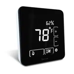
Optima!ZigBee!Thermostat!
!
!
Quick!Start!Guide
LET’S&GET&STARTED&
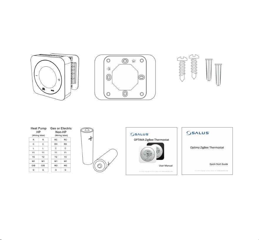
Make sure you have the following items:
Thermostat with
Mounting Plate
Trim Plate
Screws and Anchors
Wire Labels
2 x AA Alkaline
Batteries
User Manual
Quick Start Guide
!
1
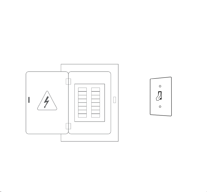
Turn&Off&the&Heating&and/or&Cooling&
Turn OFF the breakers or remove the fuses to the heating and/or cooling
systems at the electrical panel.
In some regions, there may be a switch located near the furnace.
&
!
2
Determine&Wiring&Configuration&
• Remove the old thermostat to expose the
wiring terminals.
• Take a picture of the wiring for future
reference.
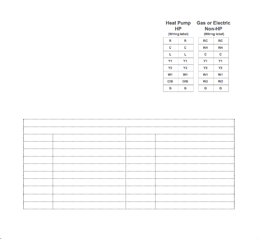
• Note the terminals attached to each wire
and attach the matching label to the ends
of the wires. Use the following table as a
reference.
* A jumper connects RC and RH since most combination heat and cooling systems use
a single transformer. For systems where separate transformers are used, remove the
jumper in place across the RC and RH terminals.
Optima Thermostat Wiring Reference
Gas, Electric, or Oil (Non-HP)
Heat Pump (HP)
RC*
24 VAC for Cooling System
R*
24 VAC for Heat Pump
RH*
24 VAC for Heating System
--*
Jumper to R
C
24 VAC Common Return
C
24 VAC Common Return
--
Reserved
L
System Monitor
Y1
Single / 1
st
Stage Cooling
Y1
Single / 1
st
Stage Compressor
Y2
2
nd
Stage Cooling
Y2
2
nd
Stage Compressor
W1
Single / 1
st
Stage Heating
W1
Emergency Heat
W2
2
nd
Stage Heating
O/B
Changeover Valve
G
Fan Signal
G
Fan Signal
--
Reserved
--
Reserved
!
3
Remove&Old&Thermostat&Terminals&
Remove the old thermostat wiring terminals
from the wall, taking care not to allow the
wiring to fall inside the wall.
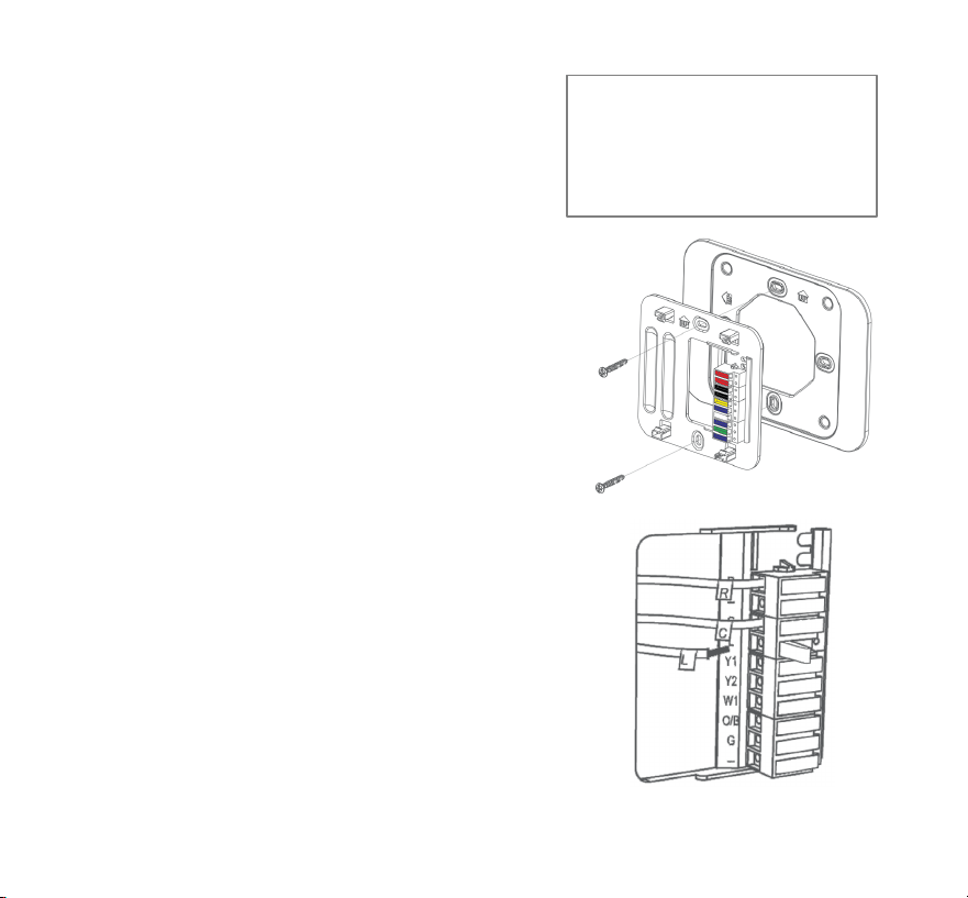
Install&Mounting&Plate&
Remove the Mounting Plate from the back of
the Optima thermostat. Use the included wall
anchors and screws to attach the Mounting
Plate to the wall, making sure that the wires
run through the center opening. Use the Trim
Plate vertically or horizontally if desired.
Attach&Wiring&
Before attaching the wires, match the wire
(using the labels) to its corresponding
terminal. Refer to the picture of the wiring
taken earlier if necessary.
• Open the terminal by lifting the latch up.
• Push each wire into the hole of the
terminal and push the latch down to
secure the wire.
TIP:! Wrap! the! wire! ends!
around!a!long!sti ck,!such! as!
a! pencil! to! ke ep! the! w ires!
from!falling!into!the!wall.!
!
4
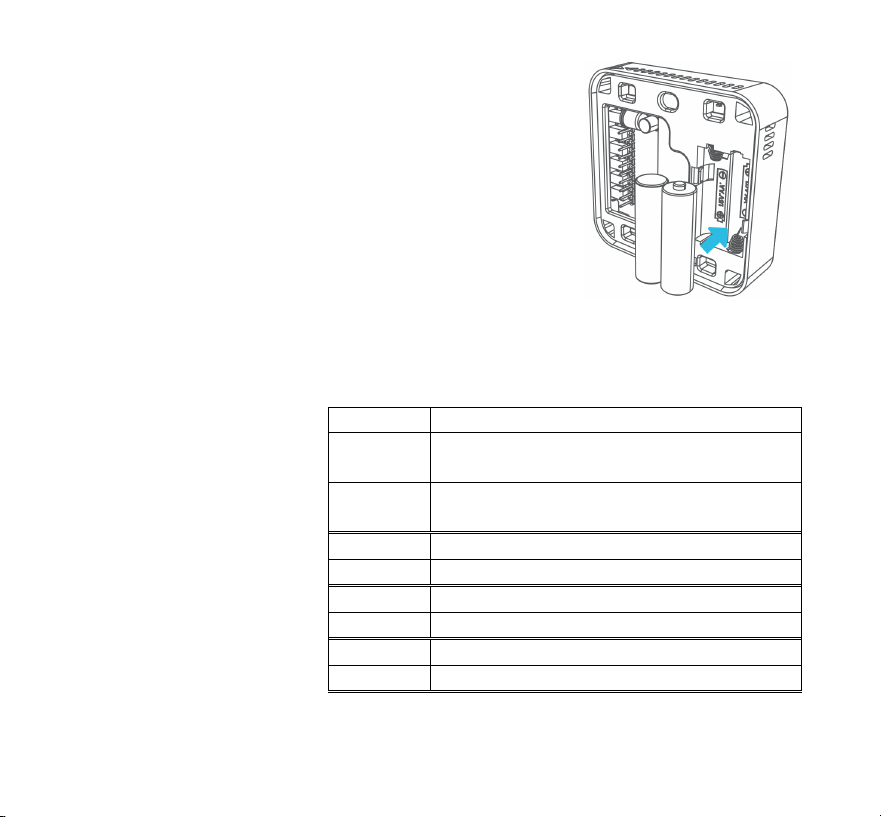
Install&Batteries&
Insert the alkaline batteries into the back of the
thermostat. Make sure the polarity of the
batteries is correct. After inserting the batteries,
the display will flash all the segments, followed by
the version number of the firmware, then display
US / CA with a blinking US.
Initial&Configuration&
When configuring the thermostat, press the + or – button or use the slider
ring to cause the desired value to blink, then press MODE to select the value.
Using the table at right,
select the country, then
the type of system.
After this configuration,
the thermostat will
display the Home
Screen, and be ready
for attachment to the
Mounting Plate.
Value
Description
US
United States – Configures thermostat for
use in the US
CA
Canada – Configures thermostat for use
in Canada
HP
Heat Pump
NON-HP
Non-Heat Pump – Gas, electric, or oil heat
O
Heat Pump with O reverse valve
B
Heat Pump with B reverse valve
FAN HE
Non-HP: Electric or Oil Heat
FAN HG
Non-HP: Gas Heat
!
5
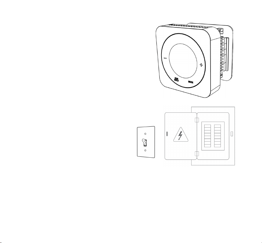
Attach&Thermostat&To&Mounting&Plate&
Attach the thermostat to the Mounting Plate
by aligning the connector pins and the plastic
retention posts and pushing the thermostat
onto the Mounting Plate.
Make sure the connector pins are not bent
and that the thermostat is fully seated on
the Mounting Plate.
Turn&Power&Back&On&To&The&
HVAC&System&
Go to the electrical service panel or
furnace switch and turn the HVAC
system back on.
Configure&Thermostat&
The thermostat can now be used as a basic local thermostat. To enable the
enhanced features, additional settings need to be configured, such as pairing
with a connected home system. Refer to the Configuring the Thermostat
section in the User Manual for more details.

!
6
SALUS&WARRANTY&
Salus North America, Inc. (“Salus”) warrants that for a period of two (2) years
(“Warranty Period”) from the date of purchase by the consumer (“Customer”), this
device, excluding batteries (“Product”), shall be free of defects in materials and
workmanship under normal use and service in accordance with all supplied
instructions. During the warranty period, Salus shall, at its option, repair or replace any
defective Products, at no charge for the device. Any replacement and/or repaired
devices are warranted for the remainder of the original Warranty Period or ninety (90)
days, whichever is longer.
This warranty does not cover removal or reinstallation costs. This warranty does not
apply to any Product (i) which has been modified, repaired, or altered, except by Salus
or an authorized Salus representative, (ii) which has not been maintained in
accordance with any handling or operating instructions supplied by Salus, or (iii) which
has been subjected to unusual physical or electrical stress, misuses, abuse, negligence
or accidents.
This warranty is the only express warranty Salus makes for the Product. Any implied
warranties, including warranties of merchantability or fitness for a particular purpose,
are limited to the Warranty Period or the shortest period allowed by law.
SALUS SHALL NOT BE LIABLE FOR ANY LOSS OR DAMAGE OF ANY KIND, INCLUDING
ANY SPECIAL, INCIDENTAL OR CONSEQUENTIAL DAMAGES RESULTING, DIRECTLY OR
INDIRECTLY, FROM ANY BREACH OF ANY WARRANTY, EXPRESS OR IMPLIED, OR ANY
OTHER FAILURE OF THIS PRODUCT. Some states and provinces do not allow the
exclusion or limitation of incidental or consequential damages, or limitation on the
duration of implied warranties of merchantability or fitness, so these exclusions or
limitations may not apply to you.
No oral or written information or advice given by Salus or a Salus-authorized
representative shall modify or extend this warranty. If any term is held to be illegal or

!
7
unenforceable, the legality or enforceability of the remaining terms shall not be
affected or impaired.
Customer’s sole and exclusive remedy under this limited warranty is product repair or
replacement as provided herein. If a Product under warranty is defective, the
Customer may:
• contact the party (“Seller”) from which the Customer purchased the Product to
obtain an equivalent replacement product after the Seller has determined that
the Product is defective and the Customer is eligible for a replacement, or,
• contact Salus Service at [email protected], to determine whether the device
qualifies for a replacement. If a replacement is warranted and is shipped prior to
the return of the device under warranty, a credit card is required and a hold may
be placed on the Customer’s credit card for the value of the replacement until the
returned device is verified as eligible for replacement, in which case, the
Customer’s credit card will not be charged.
This warranty gives you specific legal rights, and you may also have other rights that
vary from jurisdiction to jurisdiction. If you have any questions regarding this warranty,
please write Salus at:
SALUS North America, Inc.
850 Main Street
Redwood City, CA 94063

!
8
FCC&Statements&
WARNING: Changes or modifications to this unit not expressly approved by the party
responsible for compliance could void the user’s authority to operate the equipment.
This device complies with Part 15 of the FCC Rules. Operation is subject to the
following two conditions: (1) this device may not cause harmful interference, and (2)
this device must accept any interference received, including interference that may
cause undesired operation.
NOTE: This equipment has been tested and found to comply with the limits for a Class
B digital device, pursuant to Part 15 of the FCC Rules. These limits are designed to
provide reasonable protection against harmful interference in a residential installation.
This equipment generates, uses and can radiate radio frequency energy, and if not
installed and used in accordance with the instructions, may cause harmful interference
to radio communications. However, there is no guarantee that interference will not
occur in a particular installation. If this equipment does cause harmful interference to
radio or television reception, which can be determined by turning the equipment off
and on, the user is encouraged to try to correct the interference by one or more of the
following measures:
• Reorient or relocate the receiving antenna.
• Increase the separation between the equipment and receiver.
• Connect the equipment into an outlet on a circuit different from that to which the
receiver is connected.
• Consult the dealer or an experienced radio/TV technician for help.

!
9
FCC&and&Industry&Canada&
RF Radiation Exposure statement: This equipment complies with FCC and Industry
Canada RF radiation exposure limits set forth for an uncontrolled environment. This
equipment should be installed and operated with a minimum distance of 20
centimeters between the antenna and all persons.
Industry&Canada&
This device complies with Industry Canada licence-exempt RSS standard(s). Operation
is subject to the following two conditions: (1) this device may not cause interference,
and (2) this device must accept any interference, including interference that may cause
undesired operation of the device.
Le présent appareil est conforme aux CNR d'Industrie Canada applicables aux
appareils radio exempts de licence. L'exploitation est autorisée aux deux conditions
suivantes : (1) l'appareil ne doit pas produire de brouillage, et (2) l'utilisateur de
l'appareil doit accepter tout brouillage radioélectrique subi, même si le brouillage est
susceptible d'en compromettre le fonctionnement.

Version!3.1!
SALUS North America, Inc.
850 Main Street
Redwood City, CA 94063