For other language versions, please visit: www.salusinc.com
Optima S & Optima SR
Thermostat
User Guide

ii Salus
SAFETY INSTRUCTIONS
Please read these instructions carefully before installing and using the Optima S
Thermostat. This manual is meant to be used as a reference guide for the installation,
configuration and maintenance of your device.
• Follow all local and electricity supplier regulations regarding the installation or
replacement of a thermostat. An authorized, qualified installer may be required.
• Do not connect any of the terminals to the 110/220 VAC supply. The
Optima S Thermostat uses two AA batteries or a 24 VAC power source.
• Do not cover any of the vents on the thermostat.
• Do not install this unit at an altitude of over 2000 meters.
• Do not place the unit in a bathroom or area of excessive moisture.
• Do not allow the unit to get wet. This device serves as a temperature control
system only in dry, closed living and office spaces.
• Do not expose the unit to temperatures below 5°C or above 40°C, humidity
above 80%, or pollution above level 2.
• Do not expose the unit to voltage fluctuations more than +/- 10%.
• Do not use solvents or aggressive cleaning agents. A dry, soft cloth is
recommended.
The manufacturer does not accept responsibility for any damage caused by not
following these instructions.

Optima S Thermostat iii
CONTENTS
INTRODUCTION 1
INSTALLING THE THERMOSTAT 1
CONTROLS AND DISPLAY 2
BUTTONS 2
INDICATORS 3
INITITALIZATION 5
CONFIGURING THE THERMOSTAT 6
NAVIGATING THE SETTINGS MENU 6
SETTINGS 6
EQUIPMENT TYPE 7
REVERSING VALVE 7
FAN CONTROL 7
AUXILARY RELAY FUNCTION 7
AUXILARY RELAY ACTIVATION 8
TEMPERATURE SENSOR SELECT 8
INTERNAL TEMPERATURE SENSOR OFFSET 8
EXTERNAL TEMPERATURE SENSOR OFFSET 8
DELTA 1ST STAGE HEATING 9

iv Salus
DELTA 2ND STAGE HEATING 9
DELTA 1ST STAGE COOLING 9
DELTA 2ND STAGE COOLING 9
COMPRESSOR PROTECTION (Y1/Y2 MIN OFF TIME) 9
FAN DELAY 9
HEAT MAX SET POINT 10
COOL MIN SET POINT 10
DEADBAND 10
HEAT PROTECTION 10
LOCK KEYPAD SOURCE 11
LOCK LEYPAD FUNCTION 11
DISPLAY UNITS (DEGREES) 12
DISPLAY BRIGHTNESS 12
DISPLAY ON DELAY 12
LANGUAGE 12
12/24 HOUR CLOCK 12
SHOW/HIDE HUMIDITY READING 13
HUMIDITY SET POINT 13
SET TIME 13
SET DAYLIGHT SAVINGS 13
SET YEAR 13
SET DATE 13

Optima S Thermostat v
SET SCHEDULE 14
LOCK KEYPAD 14
INITIATE IDENTIFY MODE 14
JOIN NETWORK 14
JOIN NEW NETWORK 15
FACTORY RESET 15
THE HOME SCREEN 15
CHANGING THE SET POINT TEMPERATURE 16
FAN CONTROL 16
OPERATING MODE 17
LOCKING/UNLOCKING THE KEYPAD 17
SCHEDULE FUNCTION 18
TEMPORARY HOLD 19
PERMANENT HOLD 20
PAIRING OPTIMA S WITH SS909ZB TEMPERATURE SENSOR 20
SPECIFICATIONS 22
TROUBLESHOOTING 23
SALUS WARRANTY 24

vi Salus
APPENDIX A – WIRING DIAGRAMS 26
TERMINAL DEFINITIONS 26
CONVENTIONAL SINGLE TRANSFORMER HEAT AND COOL SYSTEM 27
CONVENTIONAL TWO TRANSFORMER HEAT AND COOL SYSTEM 28
FLOOR HEATING SYSTEM 29
SINGLE TRANSFORMER HEAT PUMP SYSTEM 30
TWO TRANSFORMER HEAT PUMP SYSTEM 31
APPENDIX B – REGULATORY STATEMENTS 32
FCC STATEMENTS 32
FCC AND INDUSTRY CANADA 33
INDUSTRY CANADA 33

Optima S Thermostat 1
INTRODUCTION
The Optima S is available in 2 configurations: Standard and Router to the network.
Model
Description
ST898ZB
This model functions as a standard ‘End Device’ and may be powered by
24VAC or battery.
SA898ZBR
This model functions as a Router to the network and will route messages
between devices on the network. Because of the higher level of
communications this model must be powered by 24VAC with a C-wire to
avoid draining the batteries.
INSTALLING THE THERMOSTAT
There are five basic steps to installing the thermostat:
1. Turn off power to the HVAC system.
2. Determine the wiring configuration.
3. Install new thermostat, removing old thermostat and mounting the Wall Plate
if required.
4. Turn power back on to the HVAC system.
5. Configure the new thermostat.
Please review the separate installation instructions and wiring diagrams in Appendix A
at the end of this manual for installation details.
2 Salus
CONTROLS AND DISPLAY
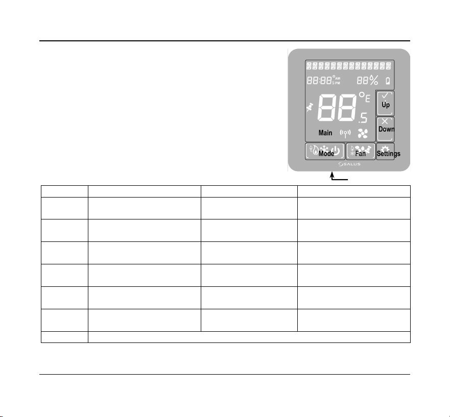
Buttons
There are six (6) button areas on the Optima S
touchscreen display as shown on the right and defined
below. The Reset button is a recessed button on the
bottom side surface of the device, below the logo.
Button
Definition
Home Screen
Settings Screens
Main
Home Screen button
Not used
Returns display to Home
Screen
Mode
Operating mode select
(Heat, Cool, Auto or Off)
Change operating
mode
Not used: mode icons are
displayed if needed
Fan
Fan mode select
(On or Auto)
Change Fan mode or
set Permanent Hold
Not used
Settings
Device settings
Enter Settings screens
Move between Settings
screens
Up
Increment or confirm
changes
Increase Set Point
Increment options /
Confirm
Down
Decrement or cancel
changes
Decrease Set Point
Decrement options /
Cancel
Reset
Restore device to Home screen
Reset
Optima S Thermostat 3
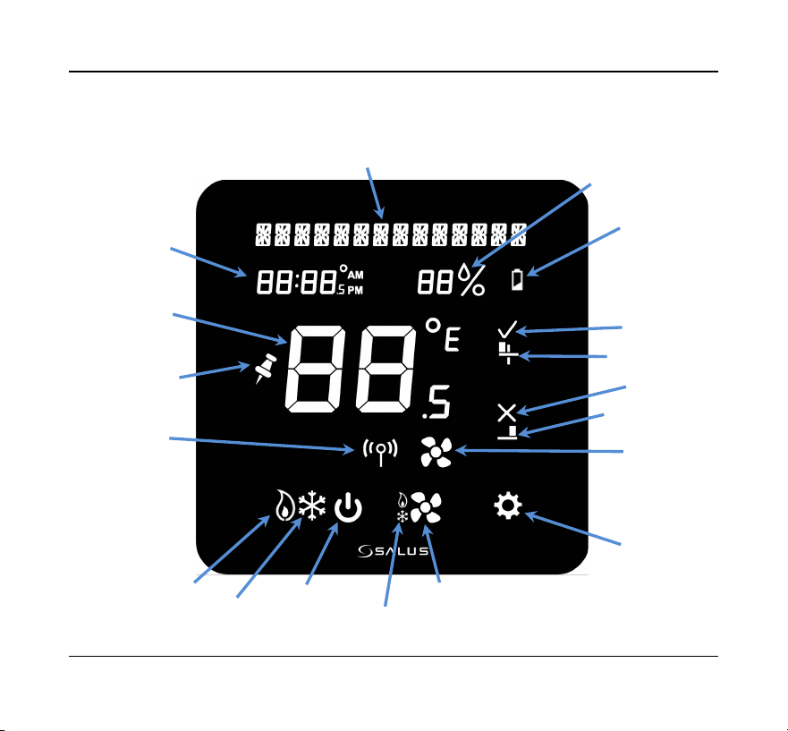
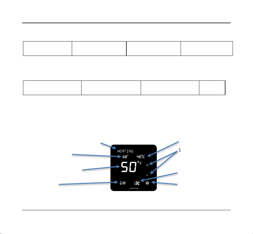
Indicators
The following indicators are available on the LCD display.
Low Battery
Humidity
Display
Message Display
Time Display
Permanent
Hold Status Icon
Main
Temperature
Display
Network
Icon
Heat Icon
Cool Icon
Off Icon
Fan Auto Icon
Fan Icon
Fan Status
Icon
Settings Icon
Confirm Icon
Increment Icon
Cancel Icon
Decrement Icon
4 Salus
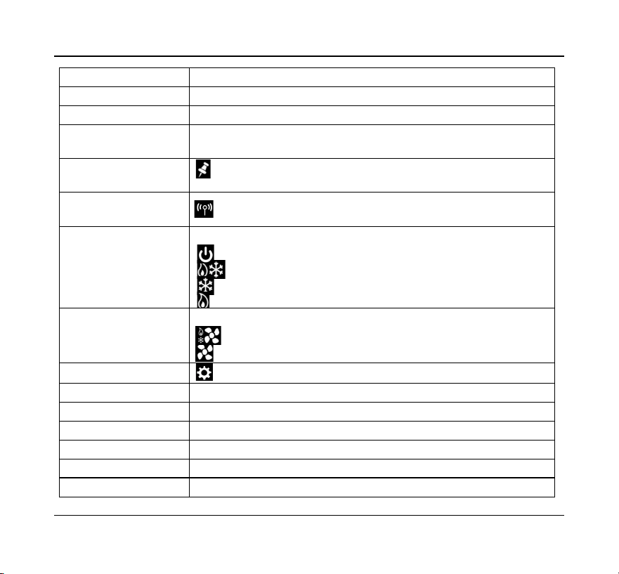
Indicator
Description
Message Display
Alphanumeric display of HVAC status and labels
Time Display
Displays time in 12- or 24-hour format if provided by the network
Main Temperature
Display
Displays the room temperature or set point as required
Permanent Hold
Status Icon
Indicates whether Permanent Hold is active
Network Icon
Indicates when the thermostat is connected to a smart home
system
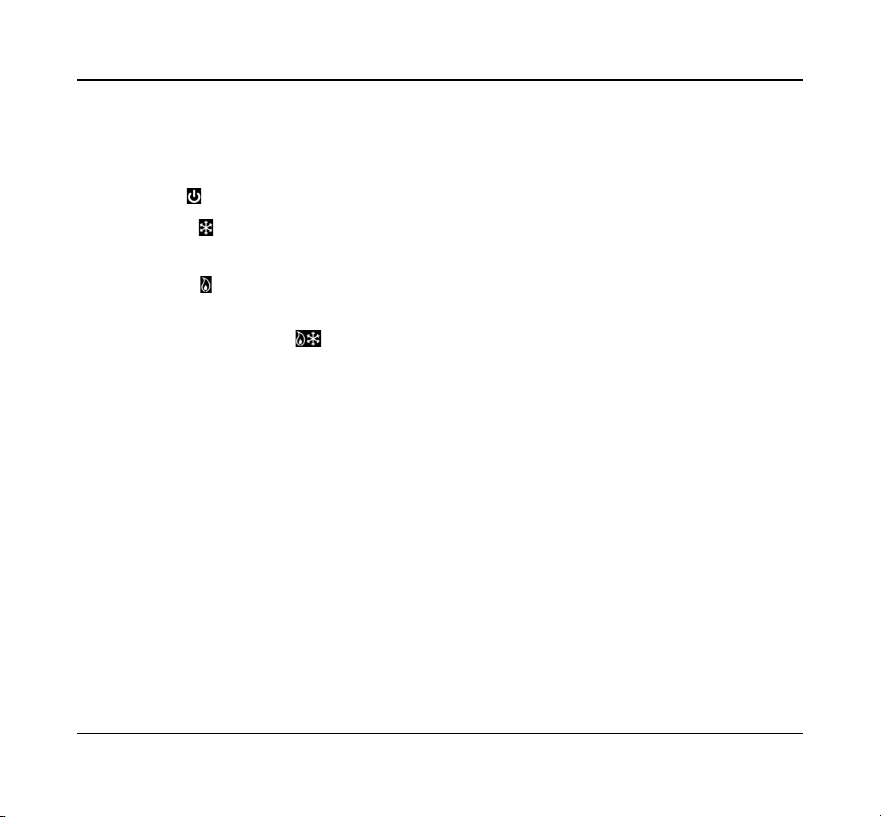
Mode Icons
HVAC operating modes as follows:
Off – System is OFF
Auto – Heat or Cool as required
Cool – AC or Cooling mode
Heat – Furnace or Heating mode
Fan Icons
Fan operating modes as follows:
Auto – Fan ON while heating or cooling
On – Fan always ON
Settings Icon
Tap for device settings, tap again to step through menu
Decrement Icon
Set device settings
Cancel Icon
Select Down to decrement changes or reject changes
Increment Icon
Set device settings
Confirm Icon
Select Up to increment changes or confirm changes
Low Battery
Indicates when the 2 AA batteries need to be replaced
Humidity
Indicates the humidity level in your home

Optima S Thermostat 5
INITIALIZATION
When power is applied to the Thermostat the display will cycle through an initialization
sequence where it performs a display test and displays the firmware version.
If it was not previously associated with a network, it will display
JOining
…
10
as it
attempts to join a network.
The number will count down from
10
minutes to
0
.
When it either finds a network, times out, or pairing is canceled by the user, the
thermostat will default to the setting
HVAC EQPT TYP
.
If there is no button activity for 30 seconds, the display will revert to the Home screen.
If the thermostat had previously joined a network, it will default to the Home screen.
Once initialization is complete, the Optima S is ready for use, or to be configured for
the intended application. The Optima S may be configured manually through the
keypad, or by using the SALUS Smart Home App. To use the desktop App go to
https://us.salusconnect.io/login
To download the mobile App search for Salus Smart Home on the Apple
App Store and Google Play
6 Salus
CONFIGURING THE THERMOSTAT
There is an extensive list of configuration settings that can be accessed by tapping the
Settings button.
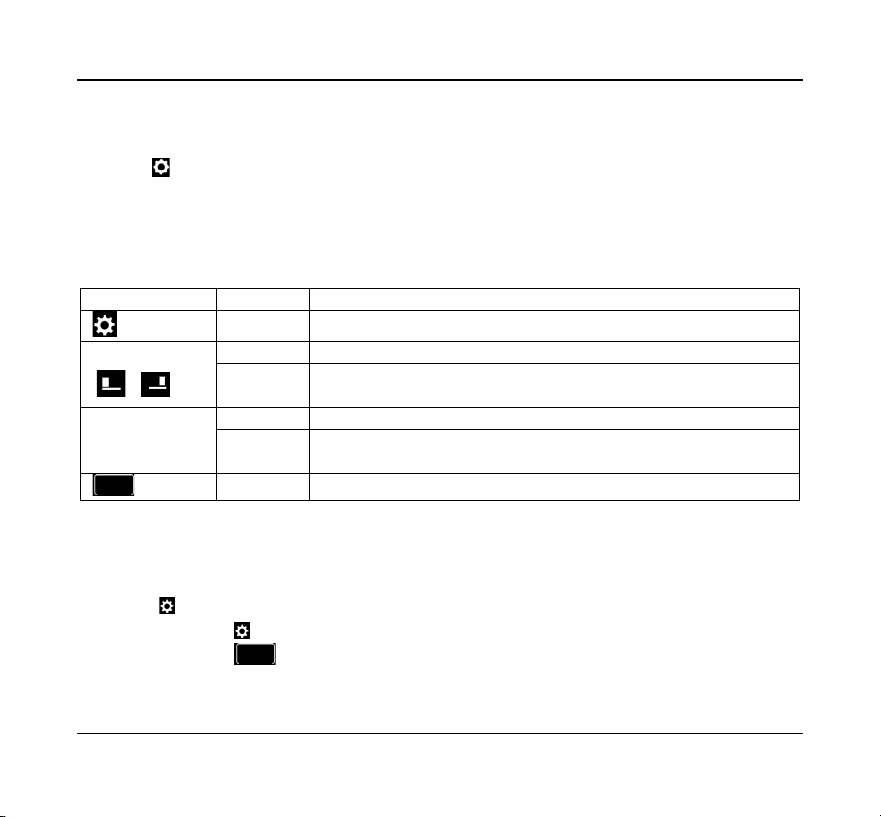
Navigating the Settings Menu
To move forward and back through the Settings menu and make any changes to the
settings, the buttons function as follows:
Touch Button
Type
Action
Settings
--
Enter Settings menu, and Save and go to next parameter setup
+ or
/
Short
Increment parameter value by 1
Long
After long press time, increment by 1 at 4 Hz rate while key
remains down
-
Short
Decrement parameter value by 1
Long
If applicable, decrement value by 1. After long press time,
decrement by 1 at 4 Hz rate while key remains down
Back
--
Save and go to previous parameter setup
After 30 seconds of no user input, changes will be saved, and the device will return to
Home screen.
Settings
Press the button to enter the Settings menu
• Pressing will save the setting and advance to the next menu item
• Pressing will save the setting and advance to the previous menu item

Optima S Thermostat 7
The thermostat defaults to a Heat Pump equipment type with configuration settings
typical for that type of equipment.
Equipment Type allows you to select the equipment the Optima S will be controlling.
EQPT TYP-
HP
(default)
For conventional Heat Pumps
+
or
–
Use the + or –
buttons to step
through the available
options.
HP+EH
For Heat Pumps with Emergency Heating
HT/AC
For forced air Heating and Cooling systems
--/AC
For Cooling only systems
HT/--
For Heating only systems
If HP or HP+EH are selected, you must set the Reversing Valve operation
REVERS VALVE-
O
(default)
Reversing valve for Heat switching to Cool
+
or
–
Use the + or – buttons to
select O or B.
B
Reversing valve for Cool switching to Heat
If Heat + AC or Heat only are selected, you must set the Fan Control
FAN CNTL-
FURNC
(default)
Used with Gas heating elements
+
or
–
Use the + or – buttons to
FURNC or TSTAT.
TSTAT
Used with Electric heating elements
The Auxiliary Relay function is shown when either Heat Pump or AC only is selected. For
all other HVAC types, the output is configured for heating.
AUX FUNC-
NONE
No function
+
or
–
Use the + or – buttons to
step through the available
options.
HMDFY
For control of a humidifier
DHMFY
For control of a dehumidifier
HEAT
For 2
nd
stage heating control (not for AC only)

8 Salus
When the Equipment Type is Heat Pump or AC only, and the Auxiliary Relay function is
set for Humidify, or Dehumidify, you must configure the relay operation.
AUX ACTIVE-
CLS
(default)
Functions like a Normally Closed relay
+
or
–
Use the + or – buttons to
select Close or Open.
OPN
Functions like a Normally Open relay
The Optima S supports a remote temperature sensor for control if the thermostat is not
located in the optimum location due to existing wiring. The remote sensor, SS909ZB,
may be paired with the thermostat and the value will be displayed on the Optima S.
The Settings menu allows you to select the internal or external sensor for control.
TEMP SEL-INT
(default)
TEMP SEL-RMT
(Zigbee)
Select Internal (INT) or remote (RMT)
temperature sensor
1
Use the + or – buttons to step
through the available options.
1
See Pairing Remote Temperature Sensor on page []
The displayed value for the temperature internal and external (if selected) sensor may
be adjusted to increase or decrease the value. The thermostat will control to this value.
INT TEMP OFFST
0
(default)
Internal temperature
offset
±4 in 0.5ºC steps
±8 in 1ºF steps
Use the + or – buttons
to step through the
available options.
RMT TEMP OFFST
0
(default)
Remote temperature
offset
±4 in 0.5ºC steps
±8 in 1ºF steps

Optima S Thermostat 9
Depending on the Equipment Type selected, you may have 2 heating stages and 2
cooling stages. The parameters below allow you to set the separation between when
the 1
st
stage energizes, and the 2
nd
stage energizes below set point (heating) and above
set point (cooling).
DLTA 1ST STAGE
(heating)
2
0.25°C/0.5°F
(default)
Heating differential
1
st
stage
0.25 - 1ºC in 0.25º steps
0.5 - 2ºF in 0.5º steps
DLTA 2ND STAGE
(heating)
2
1.0°C/2.0°F
(default)
Heating differential
2
nd
stage
0.25 – 2.0ºC in 0.25º steps
0.5 – 4.0ºF in 0.5º steps
DLTA 1ST STAGE
(cooling)
3
0.25°C/0.5°F
(default)
Cooling differential
1
st
stage
0.25 - 1ºC in 0.25º steps
0.5 - 2ºF in 0.5º steps
DLTA 2ND STAGE
(cooling)
3
1.0°C/2.0°F
(default)
Cooling differential
2
nd
stage °
0.25 – 2.0ºC in 0.25º steps
0.5 – 4.0ºF in 0.5º steps
2
Not applicable for AC only (
--AC
)
3
Not applicable for Heating only (
HT--
)
To avoid short cycling of the compressor, the Y1Y2 Min Off Time delays how long the
cooling output will remain OFF after cooling is satisfied. The output will not reenergize
until the Y1Y1 Min Off Time expires.
Y1Y2 MIN OFF T
(Not applicable for Heat Only)
5
.0
(default)
Compressor protection minimum OFF time
0 - 5 minutes in 0.5 steps
When cooling is satisfied and the output turns Off, the fan will continue to run for the
time designated by FAN DELAY to minimize condensation on the cooling coil.
FAN DELAY
0.5
(default)
Fan control relay keeps fan running for Fan Delay
after cooling stops.
0 - 5 minutes in 0.5
steps

10 Salus
The heating and cooling set points may be set to a limited range to prevent over
heating or under cooling a space to save energy.
• HEAT MAX SETPT does not appear if EQPT TYP is AC only
• COOL MIN SETPT does not appear if set to Heat only
HEAT MAX SETPT
28.5°C/83°F
(default)
Max Heating Set point
20 - 30 ºC in 0.5 º steps
68 - 86 ºF in 1 º steps
COOL MIN SETPT
8°C /46°F
(default)
Min Cooling Set point
5 - 24ºC in 0.5º steps
41 - 75ºF in 1º steps
When EQPT TYP is HP, HP+EH and HT/AC you can set a DEAD BAND which determines
the number of degrees between where cooling turns Off and heating turns On and
vice-a-versa.
DEAD BAND
1.5°C /3°F
(default)
Dead band value is used for Auto mode.
1.5 - 5ºC in 0.5ºC steps
3 - 10ºF in 1º steps
The HEAT PROTECT set point creates a limit, above which the heating outputs will be
de-energized regardless of the system configuration. Not displayed if AC only.
HEAT PROTECT
--
(default)
= Off
Heat Protect Setpoint
30 - 35ºC in 0.5 º steps
86 - 95 ºF in 1º steps

Optima S Thermostat 11
The LOCK SRC determines if the key lock function can be controlled by the thermostat
keypad (hold + and - buttons for 3+ seconds) and the App, or just by the App
LOCK SRC-KY+APP
(default)
LOCK SRC-APP
Key Lock Source
(Device+App or App Only)
Use the + or – buttons to switch between values.
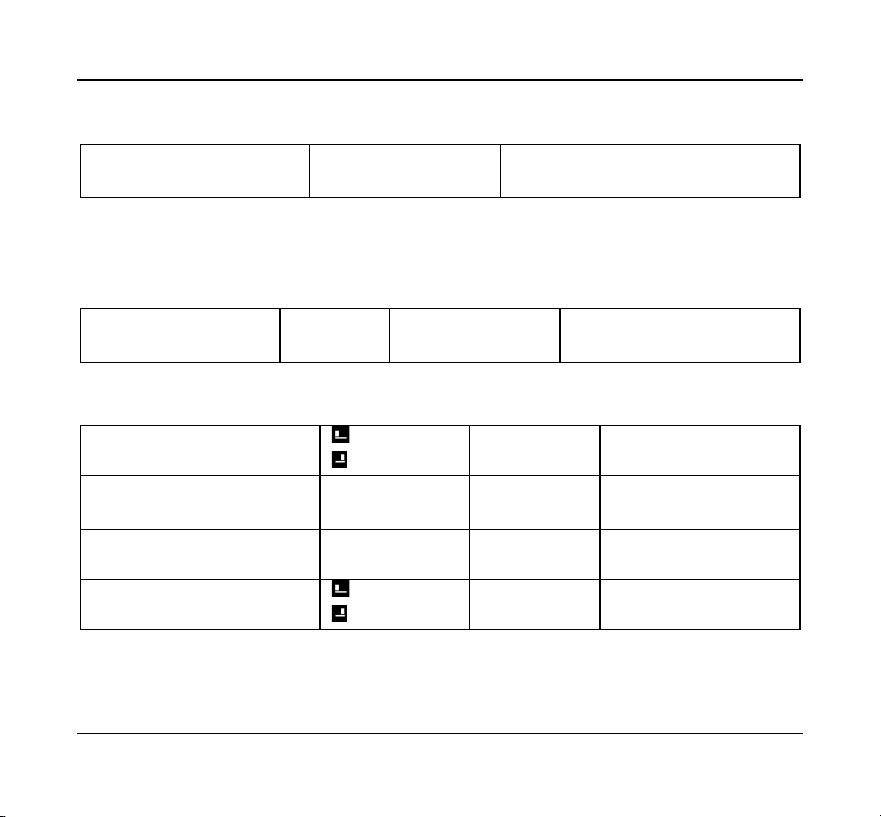
The LCK function allows you to lock any combination of Parameter Settings, Set Point,
Fan Speed, and Mode to prevent changes using the thermostat buttons.
Settings
Set Point
Fan
Mode
LCK-NONE
(default)
The Key Lock function prevents
users from making changes to
the selected items (Mode / FAN
/ Set Pt / Param) if the keypad is
locked.
The LOCK SRC parameter
determines if the buttons may
be locked from either the
keypad or the App, or only using
the App.
To lock/unlock the buttons from
the keypad press + and – for 3
seconds. The associated icons
will disappear when locked.
LCK-PARAM
Ï
LCK-SETPT
Ï
LCK-SPT+PRM
Ï
Ï
LCK-FAN
Ï
LCK-FAN+PRM
Ï
Ï
LCK-FAN+SPT
Ï
Ï
LCK-FN+SPT+PRM
Ï
Ï
Ï
LCK-MODE
Ï
LCK-MODE+PRM
Ï
Ï
LCK-MODE+SPT
Ï
Ï
LCK-MD+SPT+PRM
Ï
Ï
Ï
LCK-MODE+FAN
Ï
Ï
LCK-MD+FAN+PRM
Ï
Ï
Ï
LCK-MD+FAN+SPT
Ï
Ï
Ï
LCK-ALL
Ï
Ï
Ï
Ï

12 Salus
Temperature values may be displayed in degrees F or in C.
DEGREE UNITS
°C
°F
(default)
C/F Selection
Use the + or – buttons to switch between ºF
and ºC
The display brightness may be adjusted from 1 (dim) to 10 (brightest). Increasing
display brightness will impact battery life.
BRIGHTNESS
6
(default)
Set display brightness
Use the + or – buttons to change brightness 1 to 10
The display may be configured to dim or turn off after the selected time frame, or if AC
powered it can be set to remain on continuously.
DISPLAY ON-DM
(default)
4
DISPLAY ON-10
DISPLAY ON-20
DISPLAY ON-30
DISPLAY ON-YES
4
DM = dims display after 10 seconds
10, 20 & 30 = Display On Time in
seconds
YES = the display remains on
Use the + or – buttons to change the
display time out.
4
When powered by batteries and set to DM or YES, the display will turn off after 10 seconds.
Prompts may be shown in English, French or Spanish based on language preference.
LANGUAGE-
EN
ES
FR
English
(default)
Spanish
French
Language Selection.
Use the + or – buttons to change the language
prompts between English, French and Spanish
The time display may be set to either a 24-hour format or 12-hour format
24 HOUR CLOCK
(default)
12 HOUR CLOCK
Time Display Format
Use the + or – buttons to change
the clock setting
Optima S Thermostat 13
The Optima S has an internal humidity sensor which is displayed by default. If you do
not wish to see the humidity value, you can choose to hide the humidity reading.
SHOW HUMIDITY
(default)
HIDE HUMIDITY
Show or hide humidity
reading
Use the + or – buttons to switch between Show
and Hide Humidity.
If Equipment Type Heat Pump (HP) or AC only (--AC) is selected, and the Auxiliary Relay
function is set to Humidify or Dehumidify, the Humidify Set Point prompts will be
displayed. This is the set point around which the humidifier or dehumidifier will be
controlled.
HUMIDITY SETPT
45
%
(default)
Set point for controlling
humidifier/dehumidifier
Use the + or – buttons to change the
set point value between 20 - 60%.
If the Optima S does not have internet connection through the Gateway, you must
manually set the Time, Date and Daylight Savings time.
TIME 00:00
5
increment Hour
increment Minute
Set Time and Date
Tap the symbol to increase the
value for Hour and Minute.
DST ADJUST ON
(default)
5
DST ADJUST OFF
Enable/disable Day
Light Saving time
Use the + or – buttons to
change between On and Off.
SET YEAR 2020
(default)
5
Set Year
Use the + or – buttons to
change the value of year.
DATE M/D-1/01
(default)
5
increment Month
increment Date
Set Month and
Date
Tap the symbol to increase the
value for Month and Date.
5
Not displayed if connected to a Gateway and the internet
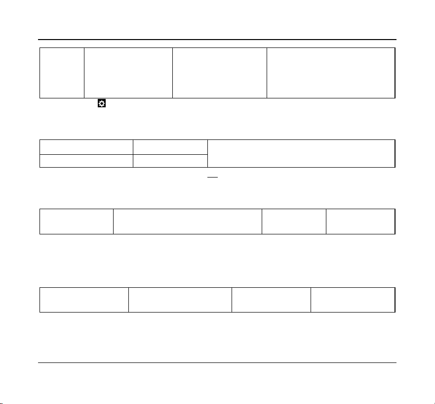
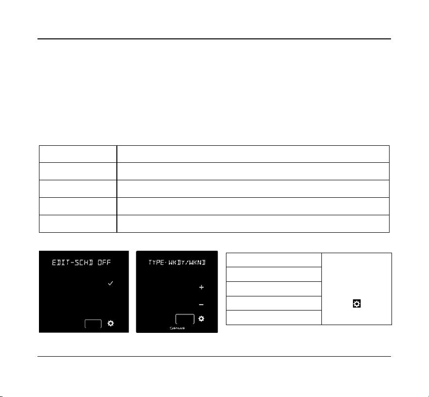
14 Salus
EDIT-
WKDY/WKND
(default)
WEEKLY
DAILY
WKDY/SA/S
SCHD OFF
Current schedule mode:
Press √ to edit schedule.
Press + or – to step through
schedule types
6
After OTA, if there is no schedule mode in
the device side and it has joined network,
then schedule mode is CLOUD, device
receives schedule setpoint from Gateway.
6
Press to access the Schedule menus to set the Interval, Time and Set Point. See Schedule configuration page []
The Lock/Unlock function allows you to lock and unlock the keypad through the
Settings menu in addition to through the keypad and/or App.
LOCK KEYS?
7
press √ to lock keys
To lock and unlock the keypad.
UNLOCK KEYS?
7
press √ to unlock keys
7
Only displayed when Lock Source = KY+APP and Key Lock Type ¹ NONE
The Identify mode sends an Identify command to paired devices which support it and
their display, or LED will flash on and off to indicate they are connected devices.
IDENTIFY?
8
Press √ to Initiate Identify mode
Identify Check 10
is displayed
Identify devices on
the shared channel
Identify mode counts
from 10 to 0 minutes
8
Most simple temperature, door/window, and water leak sensors do not support Identify.
Tapping the √ to Join Network places the thermostat in a mode where it will Join an
available Zigbee network. The network channel will be displayed for 3 seconds once
the thermostat successfully joins.
JOIN NETWORK?
Press √ to join network,
Press x to exit or 10 min time out
Initiate Join to an
available network
Displayed only if it has not
joined network.
Note: The network Gateway or Coordinator must also be in the Join mode scanning for devices.
Optima S Thermostat 15
Used to force the thermostat to leave the current network and search for a new
network to join
NEW NETWORK?
Press √ to delete network
setting and Join next network.
Delete network settings and
Join new network
Displayed only if it is Joined
to network
Note: The network Gateway or Coordinator must also be in the Join mode scanning for devices.
If the thermostat is not functioning as expected, you may reset it to factory defaults.
All configuration and network settings will be cleared.
FACTORY RESET?
Press √ to factory reset to default
settings and reboot.
Reset to Factory default settings
Note: You may first want to try a hardware reset by momentarily pressing the reset button on the
bottom of the thermostat. A hardware reset will not clear configuration and network settings.
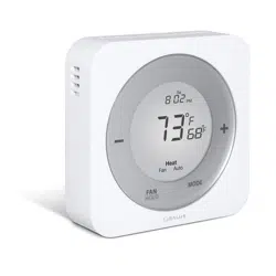
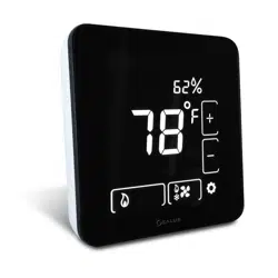
THE HOME SCREEN
The Optima S home screen provides offers basic functions using the Home Screen controls.
Time and Date or current operating mode
Set Point Temperature
Humidity value (if selected)
Current ambient temperature
Set Point adjustments
+ (increase)
– (decrease)
Mode Button
(Heat, Cool Auto, or Off)
Fan Control (On or Auto)
Settings

16 Salus
Changing the Set Point Temperature
To change the set point, simply touch the Up (+) or Down (+) button. The ambient
temperature will move to the time display area and the current set point will be
displayed in the Main Temperature display. The Message Display will indicate which set
point is being changed.
Touch the Main Temperature display to save the new set point and return to the Home
Screen. The thermostat will save the new set point after 3 seconds of no activity and
return to the Home Screen.
There is a minimum dead band between the Heat and Cool set points. If the set point
being changed gets too close to the other set point, the other set point will be adjusted
to maintain the separation. The default separation is 1.5°C / 3°F.
Fan Control
The Fan operates in one of two modes, Fan Auto and Fan On. Tapping the Fan icon
switches between the two modes.
• Fan Auto the fan will run when the thermostat calls for heat or cooling.
• Fan On the fan running continuously.
When you want the fan to be on regardless of the heating or cooling state, press to
display the Fan On icon on the home screen.
There will be a slight delay between selecting Fan On mode and the fan turning on.
Optima S Thermostat 17
Operating Mode
To change the operating mode of the system, simply touch the Mode button to select
between the following:
• Off
– The thermostat will not call for heat or cooling.
• Cool – The thermostat will call for cooling if the room temperature is above
the Cool set point.
• Heat – The thermostat will call for heat if the room temperature is below
the Heat set point.
• Auto Heat/Cool – The thermostat will call for heat or cooling as required
to keep the room temperature within the range set by the Heat and Cool set
points.
Frost Protect is active by default in all the above modes, including Off and Cool. Should
the room temperature drop below the Frost Protect set point, the thermostat will call
for heat to prevent frost damage.
The Operating Mode will appear in the Message line, alternating between current
operating mode and Day/Date.
Locking/Unlocking Keypad
If enabled. the keypad functions may be locked or unlocked from the keypad (see
settings LOCK SRC). To lock or unlock the selected functions (see settings LCK-XXX)
press the + and – buttons for 3 seconds. The buttons for the selected function will
disappear and appear as the function is locked and unlocked.
18 Salus
Schedule Function
The Optima S includes a flexible programmable schedule to vary set points based on
time of day to reduce energy when there is an opportunity to relax the comfort level.
While the schedule can be set using the keypad, it is more efficient to use the App.
There are 5 schedule modes, each having up to 6 schedule intervals. Each Interval has
a Start Time and the ability to set heating and/or cooling set points depending on the
equipment type. The 5 modes are:
WKDY/WKND
This is a 5+ 2 schedule with M/T/W/T/F with one schedule S/S another.
WEEKLY
With this schedule, every day uses the same Interval settings.
SCHD OFF
This ‘Permanent Hold’ mode turns the schedule Off and set points are set using the keypad or App.
WKDY/SA/S
This is a 5 + 1 + 1 schedule with M/T/W/T/F with one schedule Sat and Sun each with their own.
DAILY
This schedule mode each day is configured with its own schedule intervals.
To select the Schedule mode, press the √ button
TYPE-WKDY/WKND
Use the + or –
buttons to change
selection.
Press the button.
TYPE-WEEKLY
TYPE-SCHD OFF
TYPE-WKDY/SA/S
TYPE-DAILY
Optima S Thermostat 19
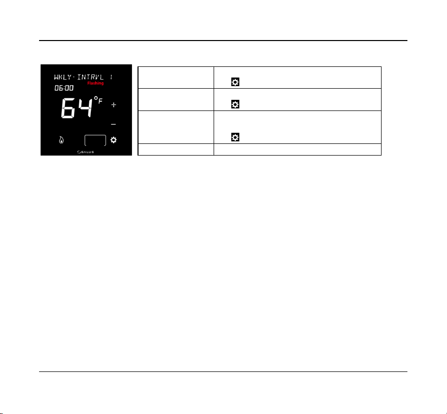
Tap the Settings button to edit the Schedule Interval 1
Continue to edit the Interval #, Time and Set Point(s) for each of the Intervals desired by
advancing the Interval and editing the Time and Temperature.
For applications where there is both heating and cooling, once you have set the heat
set point, tap the mode button so the cooling icon s
If you wish to skip an Interval (ex 4 intervals: Sleep, Wake, Leave, Return) allow the Time
setting for unwanted intervals to be blank (Time = --:-- and Temperature = - -).
When using a Daily, WKDY/WKND, or WKDY/SA/S schedule, to select the alternate
periods, with the Interval # flashing continue to tap the + or – buttons to step through
the intervals for each; Day, WKDY & WKND, and WKDY, SA and S
Temporary Hold
The thermostat may be placed in a temporary hold state which will temporarily override
the schedule settings until the next interval time is reached. To temporarily override the
scheduled set point, simply increase (+) or decrease (-) set point. When the next interval
time occurs, the thermostat will resume its programmed schedule.
Interval # will flash
Tap + or – button to select a different Interval
Tap button to move to edit time
Time will flash
Tap + or – to increase or decrease the time
Tap button to move to edit the set point temp
Temperature will flash
Tap + or – to increase or decrease the set point temp
Tap Mode to switch between heat or cool set point
Tap button to return to Interval
Interval # will flash
Tap + or – button to select a different Interval

20 Salus
Permanent Hold
To permanently override the schedule, you must turn the schedule Off either through
the thermostat menu (
TYPE-SCHD OFF
), or by using the App. When the schedule is
Off the Permanent Hold icon will appear on the thermostat display.
The current set point will be maintained until a future change is made, or The
Permanent Hold is turned Off by selecting a Schedule mode.
Pairing Optima S with SS909ZB Temperature Sensor
When the thermostat is located where it may not read the optimum temperature for
the comfort zone, a remote wireless sensor (SS909ZB) may be paired with the
thermostat and the ambient temperature of the remote sensor will be used for control.
If the sensor has not be previously associated with a Zigbee network:
1) Place the Gateway or Coordinator in Joining mode (Scan for devices)
2) Place the Optima S in Identify mode:
a) Tap the Settings button until
IDENTIFY?
is displayed
b) Tap and
IDENTIFY CHECK
10
will be displayed and count down from
10 to 0 minutes.
3) Remove the SS909ZB from the packaging:
a) Remove the front cover by lifting slightly on the top edge and pulling forward.
b) Remove the red battery tab
i) The LED on the Sensor will flash 3 times, pause, and repeat
ii) When the LED on the Sensor stops flashing it will have joined the network
and paired with the Optima S

Optima S Thermostat 21
If the SS909ZB had previously joined the network, but is not paired with the Optima S:
1) Place the Optima S in Identify mode (step 2 above).
2) Place the SS909ZB in pairing mode:
a) Hold the network button on the side of the sensor for 3 seconds until the LED
turns Red
b) Within 2 seconds of the LED turning Red:
i) Release, press, and release the network button on the sensor.
ii) The LED on the Sensor will flash 3 times, pause, and repeat
iii) When the LED on the Sensor stops flashing it will have paired with the
Optima S

22 Salus
SPECIFICATIONS
Temperature units
°C or °F
Operating temperature
32-122 °F (0-50 °C)
Indoor temperature
measurement range
32-104 °F (0-40 °C)
Protocol
ZigBee – Home Automation 1.0
AC power
18-30 VAC at RC and C terminals
Battery Power *
2 x AA Alkaline batteries
Battery Life
18 months under normal usage
Size
4.2” (L) x 4.2” (W) x 1.1” (H)
10.7cm (L) x 10.7cm (W) x 2.9cm (H)
Weight
0.76 lbs (345 g)
* The ST898ZBR thermostat functions as a router to the network. Because of the frequent need to
transmit and receive the ST898ZBR must be powered by 24VAC with RC and C wires.
Specifications may change without notice

Optima S Thermostat 23
TROUBLESHOOTING
The thermostat does not call for heat and/or cooling.
• Check that the connector pins are straight.
• Check that the thermostat is fully seated on the mounting plate. If the terminal
connections are not fully engaged, the firmware does not activate the relays.
This prevents power surges to the HVAC system.
The heat and cooling are reversed.
• Check that the thermostat is configured properly, Heat Pump or Non Heat
Pump. If Heat Pump, Check that the O/B configuration is correct.
• Check that the wiring is correct, especially the Y and W wires. If Heat Pump,
Check that the O/B wire is correct.
The fan does not turn on.
• Check that the wiring is correct, especially the G wire.
• If oil or gas heating, make sure the furnace is working. In furnace mode (FURNC),
the fan is under furnace control to avoid a blast of cold air at the start.
Display does not appear when low batteries are replaced.
• Press the Reset button on the bottom of the thermostat with a straightened
paper clip or pen point.

24 Salus
SALUS WARRANTY
SALUS North America, Inc. (“Salus”) warrants that for a period of two (2) years (“Warranty
Period”) from the date of purchase by the consumer (“Customer”), this device, excluding
batteries (“Product”), shall be free of defects in materials and workmanship under
normal use and service in accordance with all supplied instructions. During the warranty
period, Salus shall, at its option, repair or replace any defective Products, at no charge
for the device. Any replacement and/or repaired devices are warranted for the
remainder of the original Warranty Period or ninety (90) days, whichever is longer.
This warranty does not cover removal or reinstallation costs. This warranty does not
apply to any Product (i) which has been modified, repaired, or altered, except by Salus
or an authorized Salus representative, (ii) which has not been maintained in accordance
with any handling or operating instructions supplied by Salus, or (iii) which has been
subjected to unusual physical or electrical stress, misuses, abuse, negligence or
accidents.
This warranty is the only express warranty Salus makes for the Product. Any implied
warranties, including warranties of merchantability or fitness for a particular purpose,
are limited to the Warranty Period or the shortest period allowed by law.
SALUS SHALL NOT BE LIABLE FOR ANY LOSS OR DAMAGE OF ANY KIND, INCLUDING
ANY SPECIAL, INCIDENTAL OR CONSEQUENTIAL DAMAGES RESULTING, DIRECTLY OR
INDIRECTLY, FROM ANY BREACH OF ANY WARRANTY, EXPRESS OR IMPLIED, OR ANY
OTHER FAILURE OF THIS PRODUCT. Some states and provinces do not allow the
exclusion or limitation of incidental or consequential damages, or limitation on the
duration of implied warranties of merchantability or fitness, so these exclusions or
limitations may not apply to you.

Optima S Thermostat 25
No oral or written information or advice given by Salus or a Salus-authorized
representative shall modify or extend this warranty. If any term is held to be illegal or
unenforceable, the legality or enforceability of the remaining terms shall not be affected
or impaired.
Customer’s sole and exclusive remedy under this limited warranty is product repair or
replacement as provided herein. If a Product under warranty is defective, the Customer
may:
• contact the party (“Seller”) from which the Customer purchased the Product to
obtain an equivalent replacement product after the Seller has determined that the
Product is defective and the Customer is eligible for a replacement, or,
• contact Salus Service at [email protected], to determine whether the device
qualifies for a replacement. If a replacement is warranted and is shipped prior to
the return of the device under warranty, a credit card is required and a hold may
be placed on the Customer’s credit card for the value of the replacement until the
returned device is verified as eligible for replacement, in which case, the
Customer’s credit card will not be charged.
This warranty gives you specific legal rights, and you may also have other rights that
vary from jurisdiction to jurisdiction. If you have any questions regarding this warranty,
please write Salus at:
SALUS North America, Inc.
2215 Cornell Avenue
Montgomery, IL 60538
26 Salus
APPENDIX A – WIRING DIAGRAMS
Terminal Definitions
Optima S Thermostat Terminal Reference
Terminal
Non-Heat Pump
Heat Pump
RJP
Power Jumper (RH)
RC
24 VAC for Cooling System or Jumper to RJP
RH
24 VAC for Heating System
24 VAC for Heat Pump
C
24 VAC Common Return
Y1
Single or 1
st
Stage Cooling
Single or 1
st
Stage Compressor
Y2
2
nd
Stage Cooling
2
nd
Stage Compressor
W1AX
Single or 1
st
Stage Heating
Auxiliary or Emergency Heat
W2OB
2
nd
Stage Heating
Changeover Valve
G
Fan Control
L
Not Used
System Monitor
ST898ZBR requires RH/RC and a C-wire and cannot operate on batteries.
Optima S Thermostat 27
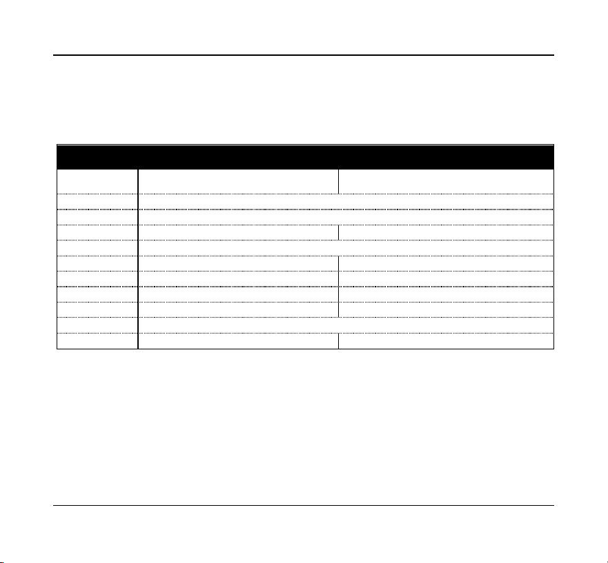
Conventional Single Transformer Heat and Cool System
RJP
RC
Y1
Y2
RH
C
G
L
W1AX
W2OB
Y2 Relay
Y1 Relay
W1 Relay
W2 Relay
Fan Relay
1
st
Cooling
2
nd
Cooling
18-30 VAC
1
st
Heat ing
2
nd
Heat ing
Fan
Transformer
AC_IN
AC_IN
POWER
SUPPLY
Line
Voltage
Jum per Wire
28 Salus
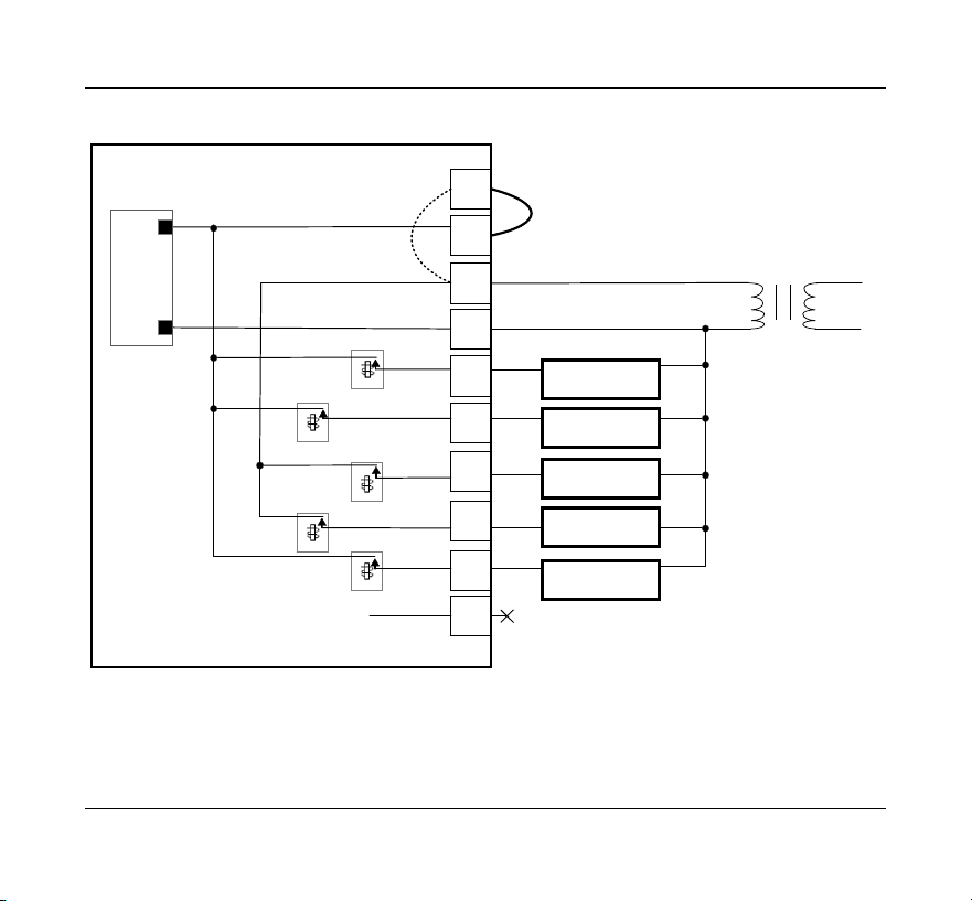
Conventional Two Transformer Heat and Cool System
RJP
RC
Y1
Y2
RH
C
G
L
W1AX
W2OB
Y2 Relay
Y1 Relay
W1 Relay
W2 Relay
Fan Relay
1
st
Cooling
2
nd
Cooling
1
st
Heat ing
2
nd
Heat ing
Fan
AC_IN
AC_IN
POWER
SUPPLY
Heating Transformer
18-30 VAC
Transformer
18-30 VAC
Line
Voltage
Line
Voltage
Optima S Thermostat 29
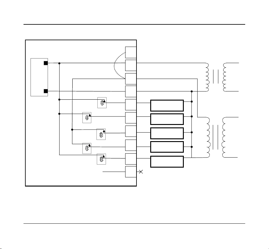
Floor Heating System
RJP
RC
Y1
Y2
RH
C
G
L
W1AX
W2OB
Y2 Relay
Y1 Relay
W1 Relay
W2 Relay
Fan Relay
Floor Heat ing
Transformer
Jum per Wire
AC_IN
AC_IN
POWER
SUPPLY
18-30 VAC
Line
Voltage
30 Salus
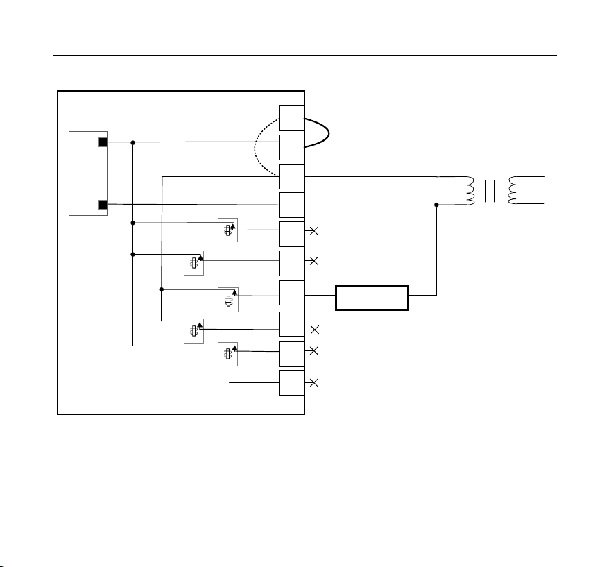
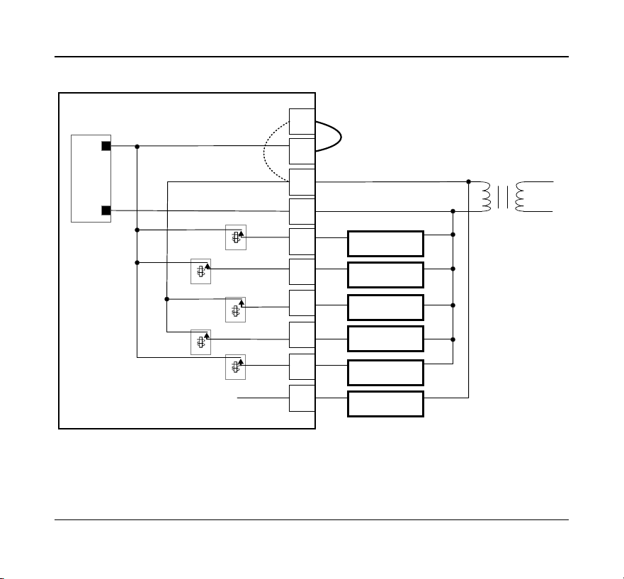
Single Transformer Heat Pump System
RJP
RC
Y1
Y2
RH
C
G
L
W1AX
W2OB
Y2 Relay
Y1 Relay
W1 Relay
W2 Relay
Fan Relay
1
st
Com pressor
2
nd
Com pressor
18-30 VAC
Auxiliary Heat ing
Changeover Valve
Fan
Transformer
AC_IN
AC_IN
POWER
SUPPLY
Line
Voltage
Jum per Wire
MCU
Fault Detect
Optima S Thermostat 31
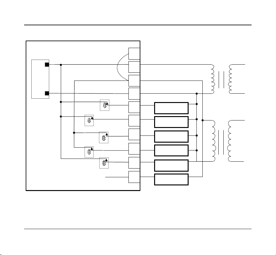
Two Transformer Heat Pump System
RJP
RC
Y1
Y2
RH
C
G
L
W1AX
W2OB
Y2 Relay
Y1 Relay
W1 Relay
W2 Relay
Fan Relay
1
st
Com pressor
2
nd
Com pressor
Auxiliary Heat ing
Changeover Valve
Fan
AC_IN
AC_IN
POWER
SUPPLY
Heating Transformer
18-30 VAC
Transformer
18-30
VAC
Line
Voltage
Line
Voltage
MCU
Fault Detect

32 Salus
APPENDIX B – REGULATORY STATEMENTS
FCC Statements
WARNING: Changes or modifications to this unit not expressly approved by the party
responsible for compliance could void the user’s authority to operate the equipment.
This device complies with Part 15 of the FCC Rules. Operation is subject to the following
two conditions: (1) this device may not cause harmful interference, and (2) this device
must accept any interference received, including interference that may cause undesired
operation.
NOTE: This equipment has been tested and found to comply with the limits for a Class
B digital device, pursuant to Part 15 of the FCC Rules. These limits are designed to
provide reasonable protection against harmful interference in a residential installation.
This equipment generates, uses and can radiate radio frequency energy, and if not
installed and used in accordance with the instructions, may cause harmful interference
to radio communications. However, there is no guarantee that interference will not
occur in a particular installation. If this equipment does cause harmful interference to
radio or television reception, which can be determined by turning the equipment off
and on, the user is encouraged to try to correct the interference by one or more of the
following measures:
• Reorient or relocate the receiving antenna.
• Increase the separation between the equipment and receiver.
• Connect the equipment into an outlet on a circuit different from that to which the
receiver is connected.
• Consult the dealer or an experienced radio/TV technician for help.

Optima S Thermostat 33
FCC and Industry Canada
RF Radiation Exposure statement: !This equipment complies with FCC and Industry
Canada RF radiation exposure limits set forth for an uncontrolled environment. This
equipment should be installed and operated with a minimum distance of 20
centimeters between the antenna and all persons.
Industry Canada
This device complies with Industry Canada license-exempt RSS standard(s). Operation
is subject to the following two conditions: (1) this device may not cause interference,
and (2) this device must accept any interference, including interference that may cause
undesired operation of the device.
Le présent appareil est conforme aux CNR d'Industrie Canada applicables aux appareils
radio exempts de licence. L'exploitation est autorisée aux deux conditions suivantes :
(1) l'appareil ne doit pas produire de brouillage, et (2) l'utilisateur de l'appareil doit
accepter tout brouillage radioélectrique subi, même si le brouillage est susceptible d'en
compromettre le fonctionnement.

SMC-UG-ST898ZB/ZBR-EN-202208v1
Copyright © SALUS North America, Inc. 2022
For Sales assistance: [email protected]
For technical support: [email protected]
SALUS North America, Inc.
2215 Cornell Avenue
Montgomery, IL 60538